
Core Shell Nanostructure: Impregnated Activated Carbon as Adsorbent for Hydrogen Sulfide Adsorption

 , and
, and
Abstract
:1. Introduction
2. Materials and Methods
2.1. Materials
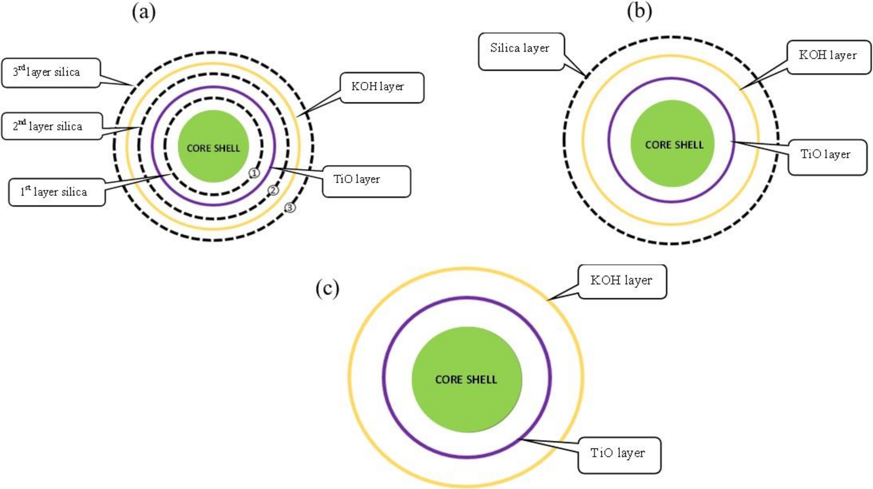
2.2. Preparation of Core Shell Activated Carbon (CS/CAC)
2.3. Characterization of Adsorbents
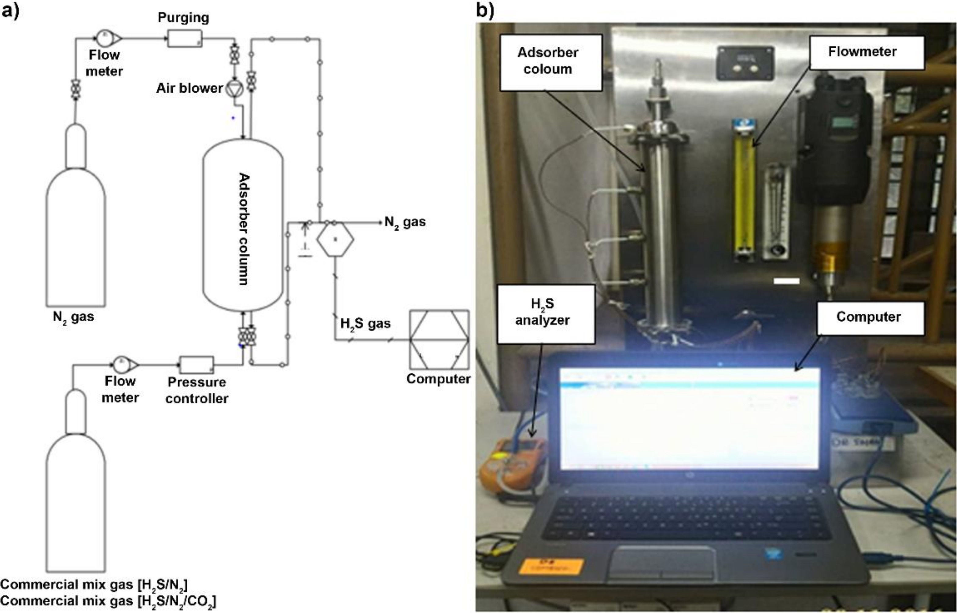
2.4. Operation of H2S Adsorber Column
3. Results and Discussion
3.1. H2S Adsorption Capacity
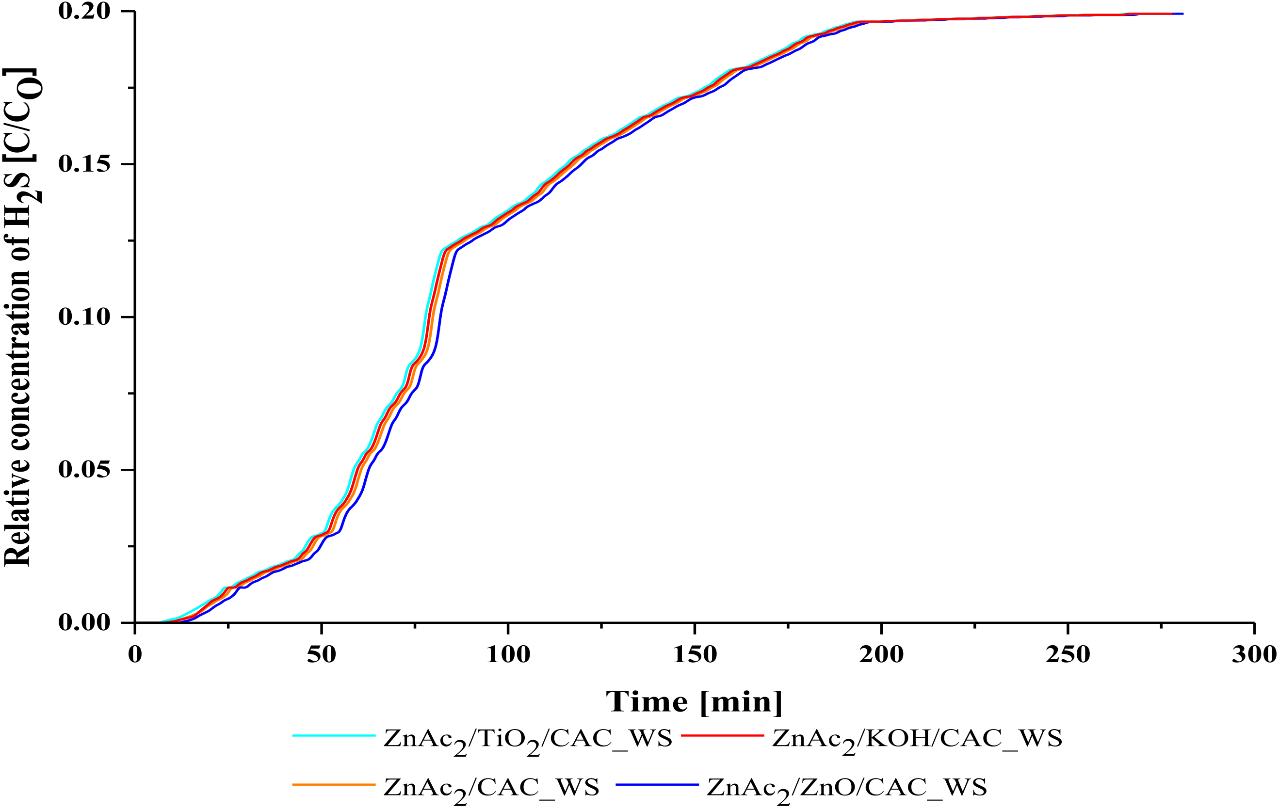
3.1.1. The Performance of CS/CAC_WS
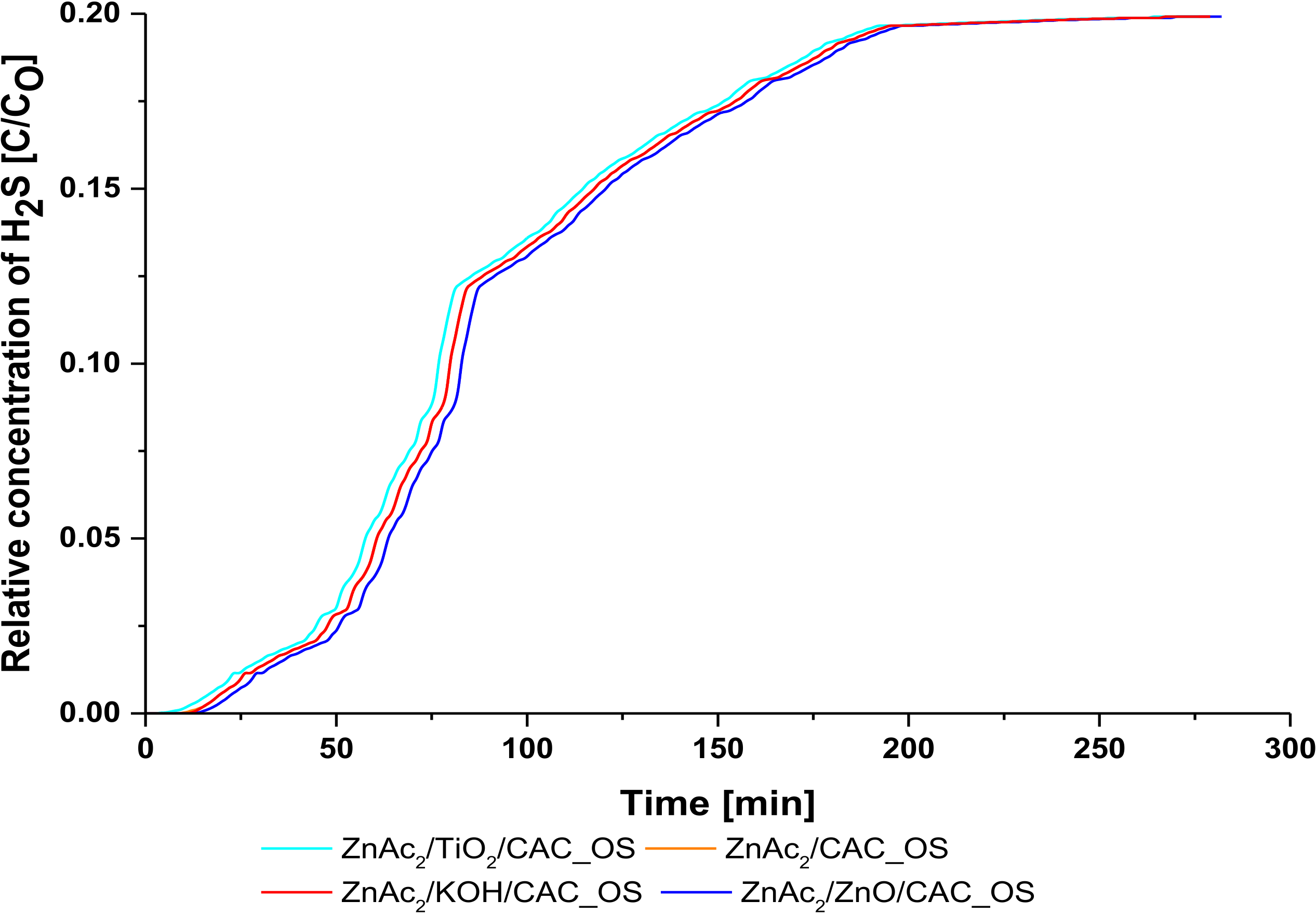
3.1.2. The Performance of CS/CAC_OS
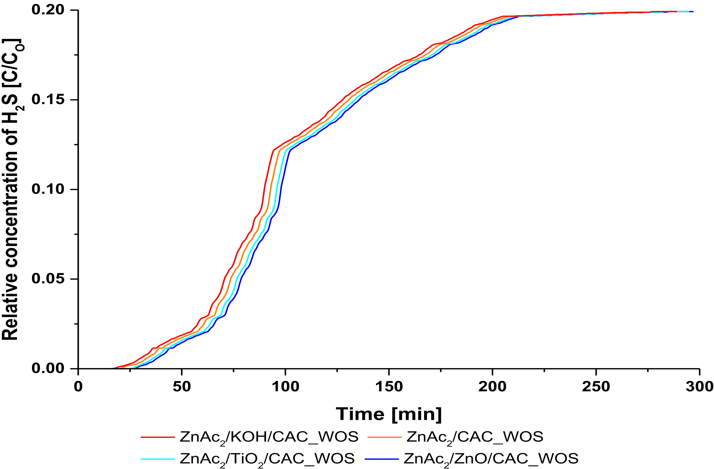
3.1.3. The Performance of CS/CAC_WOS
3.2. Characterization of Fresh Adsorbents
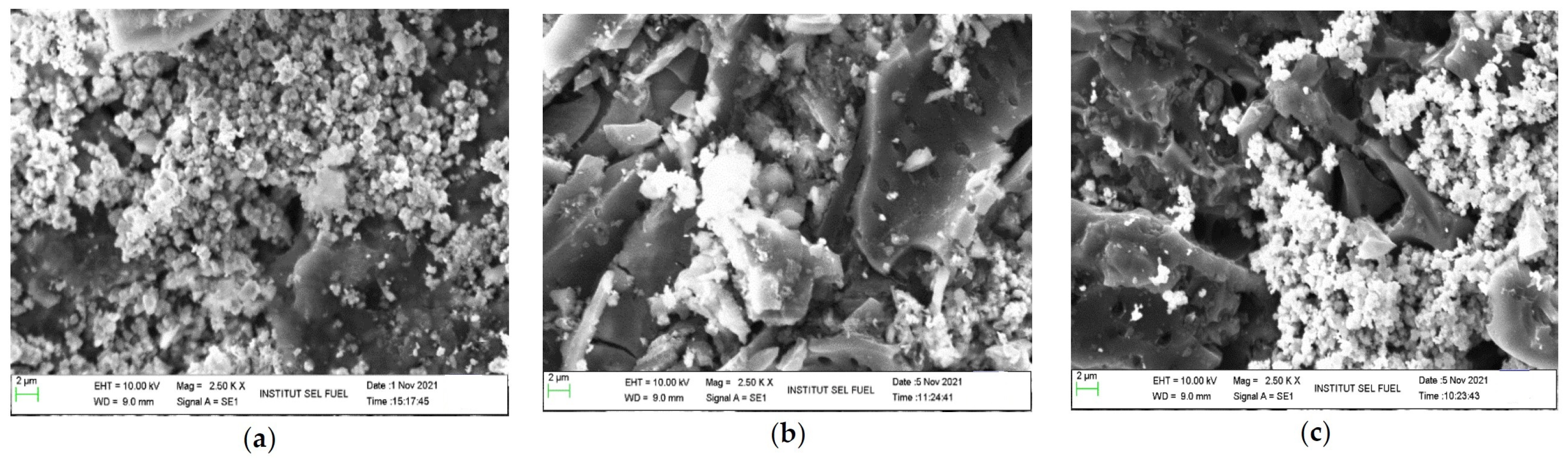
3.2.1. SEM-EDX Analysis
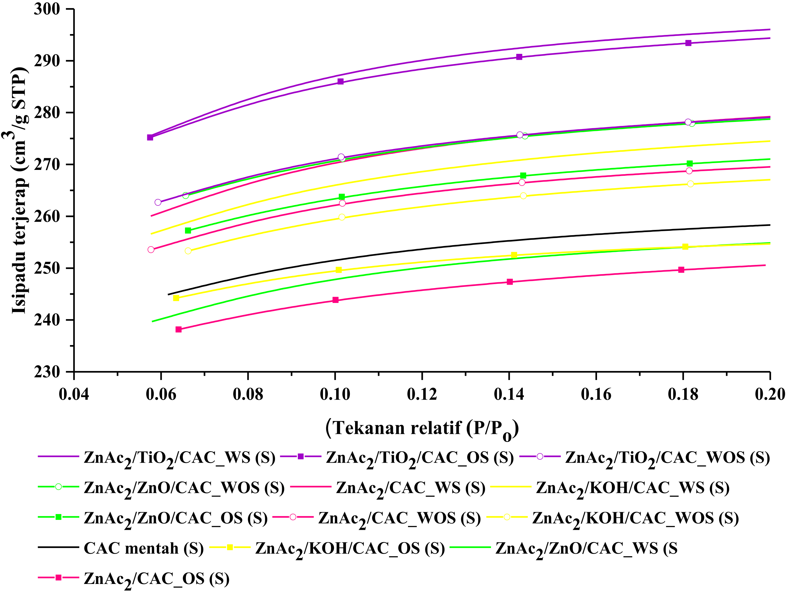
3.2.2. BET Analysis
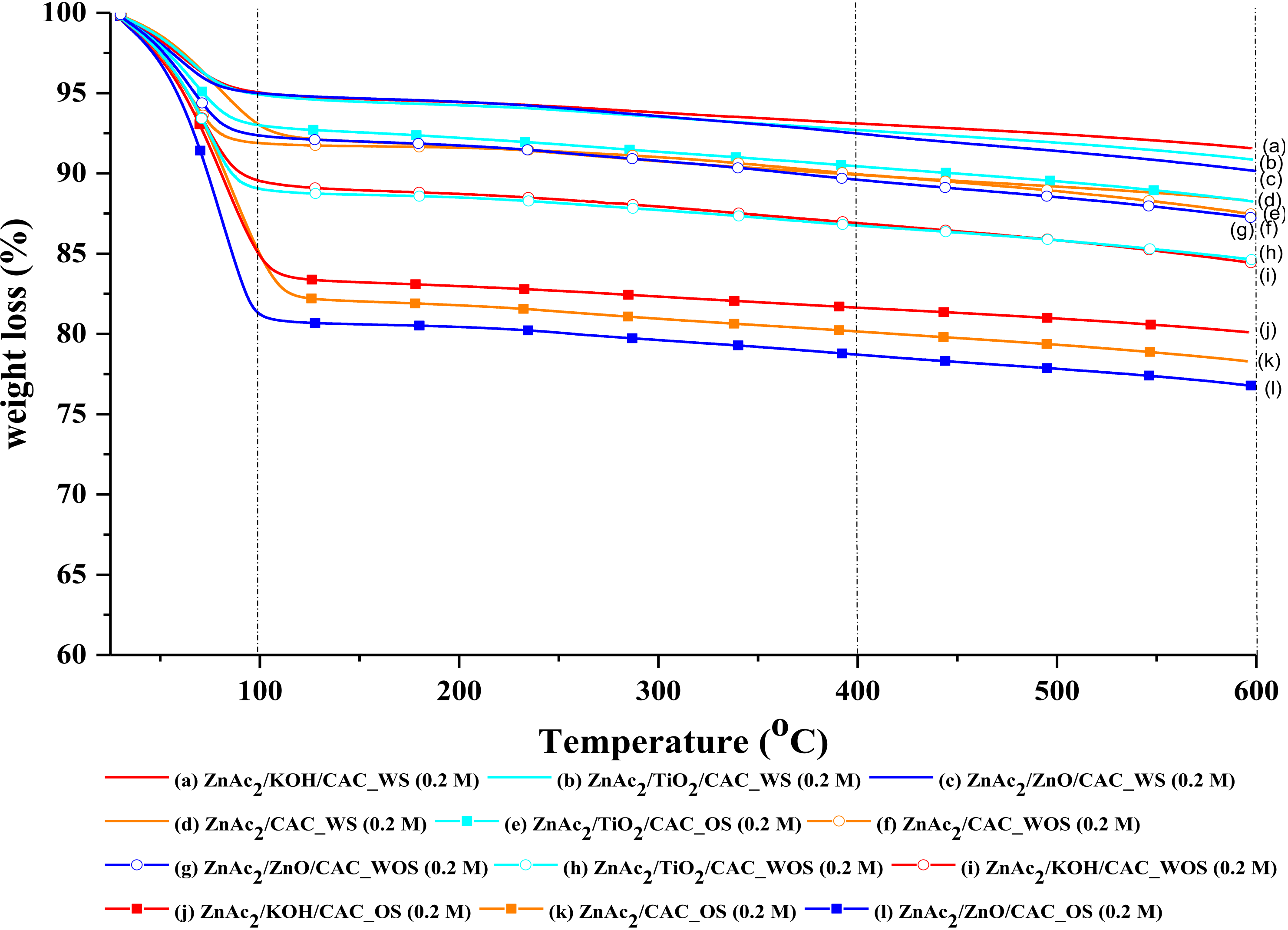
3.2.3. TGA Analysis
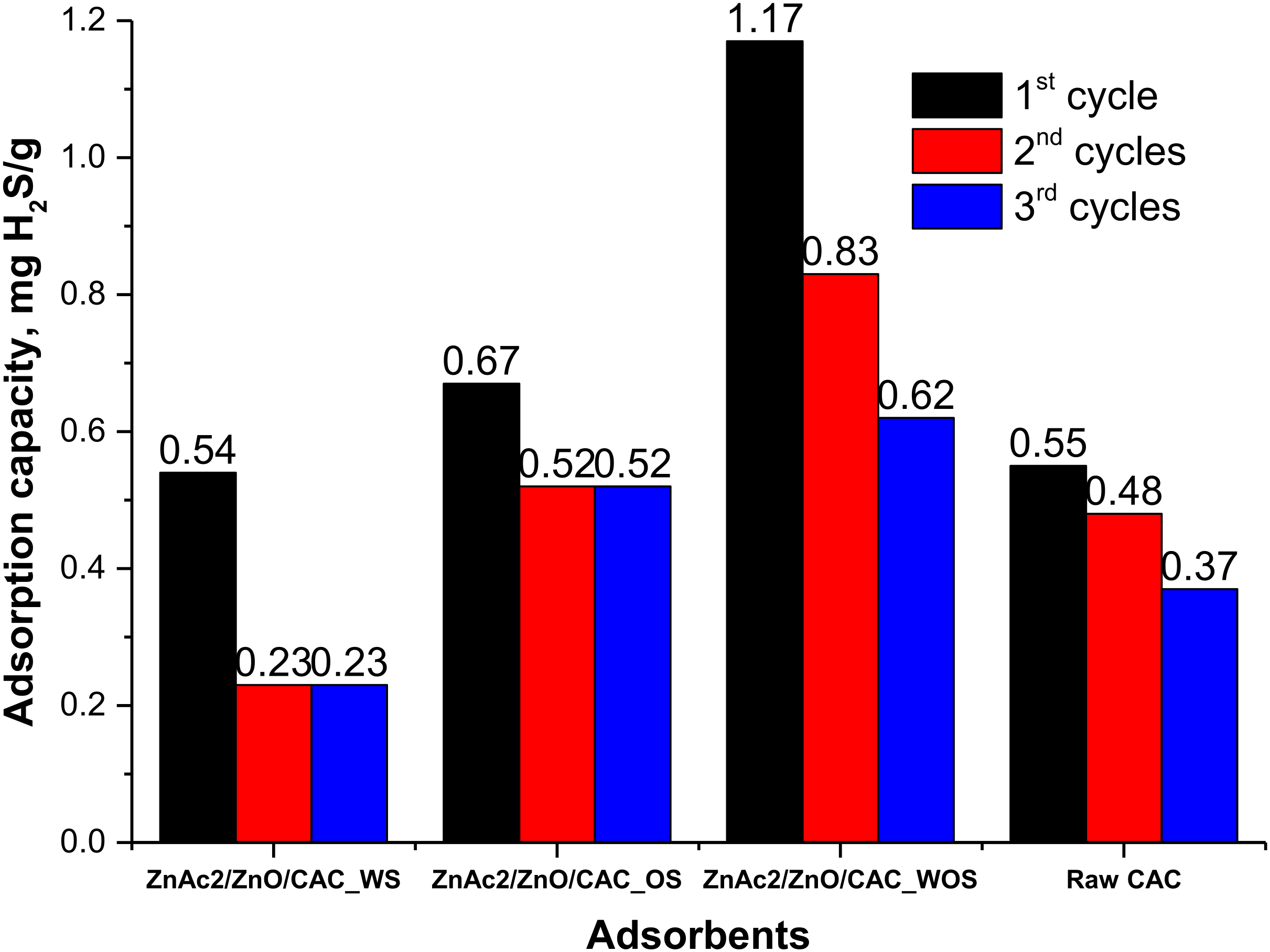
3.3. Regeneration of Adsorbents
4. Conclusions
Author Contributions
Funding
Institutional Review Board Statement
Informed Consent Statement
Data Availability Statement
Conflicts of Interest
References
- Anhuradha, S.; Vijayagopal, V.; Radha, P.; Ramanujam, R. Review: Kinetic studies and anaerobic co-digestion of vegetable market waste and sewage sludge. Wiley Inter Sci. 2017, 35, 197–199. [Google Scholar]
- Arthur, R.; Baidoo, M.F.; Antwi, E. Biogas as a potential renewable energy source: A Ghanaian case study. Renew. Energy 2011, 36, 1510–1516. [Google Scholar] [CrossRef]
- Zulkefli, N.N.; Masdar, M.S.; Wan Isahak, W.N.R.; Abu Bakar, S.N.H.; Abu Hasan, H.; Mohd Sofian, N. Application of response surface methodology for preparation of ZnAC2/CAC adsorbents for hydrogen sulfide (H2S) capture. Catalysts 2021, 11, 545. [Google Scholar] [CrossRef]
- Sidek, M.Z.; Masdar, M.S.; Dir, N.M.H.N.; Amran, N.F.A.; Singh, S.K.D.A.; Loong, W.W. Review: Integrasi sistem penulenan biohidrogen dan aplikasi sel fuel. J. Eng. 2018, 1, 41–48. [Google Scholar]
- Shah, D.; Nagarseth, P.H. Review: Low-cost biogas purification system for application of bio CNG as fuel for automobile engines. Int. J. Innov. Sci. Eng. Technol. 2015, 2, 308–312. [Google Scholar]
- Bamdad, H.; Hawboldt, K.; MacQuarrie, S. A review on common adsorbents for acid gases removal: Focus on biochar. Renew. Sustain. Energy Rev. 2018, 81, 1705–1720. [Google Scholar] [CrossRef]
- Khabazipour, M.; Mansoor, A. Removal of hydrogen sulfide from gas streams using porous materials: A review. Ind. Eng. Chem. Res. 2019, 58, 22133–22164. [Google Scholar] [CrossRef]
- Zulkefli, N.N.; Masdar, M.S.; Jahim, J.; Harianto, E.H. Overview of H2S removal technologies from biogas production. Int. J. Appl. Eng. Res. 2016, 11, 10060–10066. [Google Scholar]
- Zulkefli, N.N.; Masdar, M.S.; Wan Isahak, W.N.R.; Jahim, J.; Rejab, S.A.; Chien Lye, C. Review: Removal of hydrogen sulfide from a biogas mimic by using impregnated activated carbon adsorbent. PlusOne Publ. 2019, 1, 1–25. [Google Scholar]
- Zhang, Q.; Lee, I.; Joo, J.B.; Zaera, F.; Yin, Y. Review: Core à shell nanostructured catalysts. Am. Chem. Soc. Publ. 2012, 46, 1816–1824. [Google Scholar]
- Voon, C.H.; Lim, B.Y.; Ho, L.N. Review: Silicon carbide nanomaterials. Synth. Inorg. Nanomater. 2018, 1, 213–253. [Google Scholar]
- Huang, Y.; Wang, R. Review: Highly selective separation of H2S and CO2 using a H2S-imprinted polymers loaded on a polyoxometalate@Zr-based metal-organic framework with a core-shell structure at ambient temperature. J. Mater. Chem. 2019, 7, 12105–12114. [Google Scholar] [CrossRef]
- Chaudhuri, R.G.; Paria, S. Review: Core/shell nanoparticles: Classes, properties, synthesis mechanisms, characterization and applications. Am. Chem. Soc. Publ. 2012, 4, 2373–2433. [Google Scholar]
- Zulkefli, N.N.; Khaia, T.Z.; Nadaraja, S.; Venugopal, N.R.; Yusri, N.A.M.; Sofian, N.M.; Masdar, M.S. Capabilities dual chemical mixture (DCM) adsorbents through metal anchoring in H2S captured. Solid State Technol. 2020, 63, 181–191. [Google Scholar]
- Elyassi, B.; Al Wahedi, Y.; Rajabbeigi, N.; Kumar, P.; Jeong, J.S.; Zhang, X.; Kumar, P.; Balasubramanian, V.V.; Katsiotis, M.S.; Mkhoyan, K.A.; et al. A high-performance adsorbent for hydrogen sulfide removal. Microporous Mesoporous Mater. 2014, 190, 152–155. [Google Scholar] [CrossRef]
- Georgiadis, A.G.; Charisiou, N.D.; Goula, M.A. Removal of hydrogen sulfide from various industrial gases: A review of the most promising adsorbing materials. Catalysts 2020, 10, 521. [Google Scholar] [CrossRef]
- Yang, C.; Wang, J.; Fan, H.-L.; Shangguan, J.; Mi, J.; Huo, C. Contributions of tailored oxygen vacancies in ZnO/Al2O3 composites to the enhanced ability for H2S removal at room temperature. Fuel 2018, 215, 695–703. [Google Scholar] [CrossRef]
- Bagreev, A.; Bandosz, T.J. H2S adsorption/oxidation on unmodified activated carbons: Importance of prehumidification. Carbon 2001, 39, 2303–2311. [Google Scholar] [CrossRef]
- Primavera, A.; Trovarelli, A.; Andreussi, P.; Dolcetti, G. The effect of water in the low-temperature catalytic oxidation of hydrogen sulfide to sulfur over activated carbon. Appl. Catal. A Gen. 1998, 173, 185–192. [Google Scholar] [CrossRef]
- Thommes, M.; Kaneko, K.; Neimark, A.V.; Olivier, J.P.; Rodriguez-Reinoso, F.; Rouquerol, J.; Sing, K.S.W. Physisorption of gases, with special reference to the evaluation of surface area and pore size distribution (IUPAC Technical Report). Pure Appl. Chem. 2015, 87, 1051–1069. [Google Scholar] [CrossRef] [Green Version]
- Roque-Malherbe, R.M. Adsorption and Diffusion in Nanoporous Materials; CRC Press: Boca Raton, FL, USA, 2007. [Google Scholar] [CrossRef]
- Kitsou, I.; Panagopoulos, P.; Maggos, T.; Tsetsekou, A. ZnO-coated SiO2 nanocatalyst preparation and its photocatalytic activity over nitric oxides as an alternative material to pure ZnO. Appl. Surf. Sci. 2019, 473, 40–48. [Google Scholar] [CrossRef]
- Vinodhini, V.; Das, N. Packed bed column studies on Cr (VI) removal from tannery wastewater by neem sawdust. Desalination 2010, 264, 9–14. [Google Scholar] [CrossRef]
- Sethupathi, S.; Kai, Y.C.; Kong, L.L.; Munusamy, Y.; Bashir, M.J.K.; Iberahim, N. Preliminary study of sulfur dioxide removal using calcined egg shell. Malays. J. Anal. Sci. 2017, 21, 719–725. [Google Scholar] [CrossRef]
- Yang, C.; Florent, M.; de Falco, G.; Fan, H.; Bandosz, T.J. ZnFe2O4/activated carbon as a regenerable adsorbent for catalytic removal of H2S from air at room temperature. Chem. Eng. J. 2020, 394, 124906. [Google Scholar] [CrossRef]


| Adsorbents | Breakthrough Time, TB (min) | Adsorption Capacity, q (mg H2S/g) |
|---|---|---|
| ZnAc2/CAC_WS | 8 | 0.33 |
| ZnAc2/ZnO/CAC_WS | 13 | 0.54 |
| ZnAc2/TiO2/CAC_WS | 7 | 0.29 |
| ZnAc2/KOH/CAC_WS | 9 | 0.38 |
| Adsorbents | Breakthrough Time, TB (min) | Adsorption Capacity, q (mg H2S/g) |
|---|---|---|
| ZnAc2/CAC_OS | 10 | 0.42 |
| ZnAc2/ZnO/CAC_OS | 16 | 0.67 |
| ZnAc2/TiO2/CAC_OS | 13 | 0.54 |
| ZnAc2/KOH/CAC_OS | 12 | 0.50 |
| Adsorbents | Breakthrough Time, TB (min) | Adsorption Capacity, q (mg H2S/g) |
|---|---|---|
| ZnAc2/CAC_WOS | 21 | 0.88 |
| ZnAc2/ZnO/CAC_WOS | 28 | 1.17 |
| ZnAc2/TiO2/CAC_WOS | 26 | 1.09 |
| ZnAc2/KOH/CAC_WOS | 17 | 0.71 |
| Adsorbents | C | Ca | O | Zn | Ti | K | Si |
|---|---|---|---|---|---|---|---|
| ZnAc2/CAC_WS | 40.70 | 0.73 | 21.66 | 11.08 | 1.14 | 1.21 | 23.48 |
| ZnAc2/KOH/CAC_WS | 36.71 | 0.32 | 23.31 | 7.06 | 1.33 | 5.61 | 25.66 |
| ZnAc2/ZnO/CAC_WS | 30.96 | 1.69 | 28.63 | 15.98 | 1.27 | 1.08 | 20.39 |
| ZnAc2/TiO2/CAC_WS | 20.51 | 0.44 | 27.54 | 9.43 | 22.76 | 1.73 | 17.59 |
| ZnAc2/CAC_OS | 43.26 | 0.45 | 33.32 | 12.84 | 1.53 | 1.19 | 7.41 |
| ZnAc2/KOH/CAC_OS | 38.99 | 0.48 | 37.28 | 9.46 | 1.09 | 7.69 | 5.01 |
| ZnAc2/ZnO/CAC_OS | 39.78 | 0.51 | 38.76 | 13.3 | 1.36 | 1.08 | 5.21 |
| ZnAc2/TiO2/CAC_OS | 28.33 | 0.39 | 34.23 | 10.11 | 21.19 | 1.44 | 4.31 |
| ZnAc2//CAC_WOS | 52.19 | 0.42 | 32.43 | 12.16 | 1.09 | 1.71 | 0.00 |
| ZnAc2/KOH/CAC_WOS | 30.22 | 1.19 | 43.50 | 19.11 | 1.75 | 4.23 | 0.00 |
| ZnAc2/ZnO/CAC_WOS | 39.06 | 0.32 | 45.58 | 12.35 | 1.15 | 1.54 | 0.00 |
| ZnAc2/TiO2/CAC_WOS | 31.22 | 0.36 | 37.70 | 2.83 | 26.15 | 1.74 | 0.00 |
| Adsorbents | BET Surface Area, (m2/g) | Pore Volume (cm3/g) | Micropore Surface Area, (m2/g) | Pore Size (Å) |
|---|---|---|---|---|
| ZnAc2/CAC_WOS (S) | 913.24 | 0.43 | 757.29 | 18.75 |
| ZnAc2/ZnO/CAC_WOS (S) | 939.76 | 0.45 | 769.79 | 19.14 |
| ZnAc2/TiO2/CAC_WOS (S) | 945.02 | 0.45 | 775.19 | 19.09 |
| ZnAc2/KOH/CAC_WOS (S) | 899.57 | 0.43 | 739.48 | 19.04 |
| ZnAc2/CAC_WS (S) | 948.93 | 0.45 | 758.86 | 18.89 |
| ZnAc2/ZnO/CAC_WS (S) | 863.61 | 0.42 | 715.08 | 19.25 |
| ZnAc2/TiO2/CAC_WS (S) | 1006.38 | 0.47 | 816.05 | 18.77 |
| ZnAc2/KOH/CAC_WS (S) | 932.19 | 0.44 | 751.62 | 19.01 |
| ZnAc2/CAC_OS (S) | 846.22 | 0.41 | 699.19 | 19.20 |
| ZnAc2/ZnO/CAC_OS (S) | 913.18 | 0.44 | 751.86 | 19.38 |
| ZnAc2/TiO2/CAC_OS (S) | 999.05 | 0.48 | 812.90 | 18.82 |
| ZnAc2/KOH/CAC_OS (S) | 865.60 | 0.39 | 746.79 | 18.32 |
| Raw CAC | 899.05 | 0.42 | 730.02 | 18.82 |
| Adsorbents | Temperature Range (°C) | Wt. Loss (%) |
|---|---|---|
| ZnAc2/CAC_WOS | 25–100 | 8.0 |
| 100–400 | 1.9 | |
| 400–600 | 2.5 | |
| ZnAc2/ZnO/CAC_WOS | 25–100 | 7.5 |
| 100–400 | 2.8 | |
| 400–600 | 2.4 | |
| ZnAc2/TiO2/CAC_WOS | 25–100 | 10.8 |
| 100–400 | 2.3 | |
| 400–600 | 2.2 | |
| ZnAc2/KOH/CAC_WOS | 25–100 | 10.3 |
| 100–400 | 2.6 | |
| 400–600 | 2.5 | |
| ZnAc2/ZnO/CAC_WS | 25–100 | 4.9 |
| 100–400 | 2.5 | |
| 400–600 | 2.3 | |
| ZnAc2/ZnO/CAC_OS | 25–100 | 18.6 |
| 100–400 | 2.5 | |
| 400–600 | 2.0 | |
| ZnAc2/CAC | 25–100 | 6.9 |
| 100–400 | 6.1 | |
| 400–600 | 3.1 | |
| Raw CAC | 25–100 | 15.4 |
| 100–400 | 4.8 | |
| 400–600 | 4.9 |
Publisher’s Note: MDPI stays neutral with regard to jurisdictional claims in published maps and institutional affiliations. |
© 2022 by the authors. Licensee MDPI, Basel, Switzerland. This article is an open access article distributed under the terms and conditions of the Creative Commons Attribution (CC BY) license (https://creativecommons.org/licenses/by/4.0/).
Share and Cite
Zulkefli, N.N.; Seladorai, R.; Masdar, M.S.; Mohd Sofian, N.; Wan Isahak, W.N.R. Core Shell Nanostructure: Impregnated Activated Carbon as Adsorbent for Hydrogen Sulfide Adsorption. Molecules 2022, 27, 1145. https://doi.org/10.3390/molecules27031145
Zulkefli NN, Seladorai R, Masdar MS, Mohd Sofian N, Wan Isahak WNR. Core Shell Nanostructure: Impregnated Activated Carbon as Adsorbent for Hydrogen Sulfide Adsorption. Molecules. 2022; 27(3):1145. https://doi.org/10.3390/molecules27031145
Chicago/Turabian StyleZulkefli, Nurul Noramelya, Rajeevelosana Seladorai, Mohd Shahbudin Masdar, Nabilah Mohd Sofian, and Wan Nor Roslam Wan Isahak. 2022. "Core Shell Nanostructure: Impregnated Activated Carbon as Adsorbent for Hydrogen Sulfide Adsorption" Molecules 27, no. 3: 1145. https://doi.org/10.3390/molecules27031145