
Negative Dielectric Anisotropy Liquid Crystal with Improved Photo-Stability, Anti-Flicker, and Transmittance for 8K Display Applications
 and
and
Abstract
:1. Introduction
2. Results & Discussions
2.1. The Reliability Improvement of Negative Dielectric Anisotropy Compounds
2.1.1. The Photo-Stability Improvement of Negative Dielectric Anisotropy Compounds
2.1.2. The Improvement of Flicker
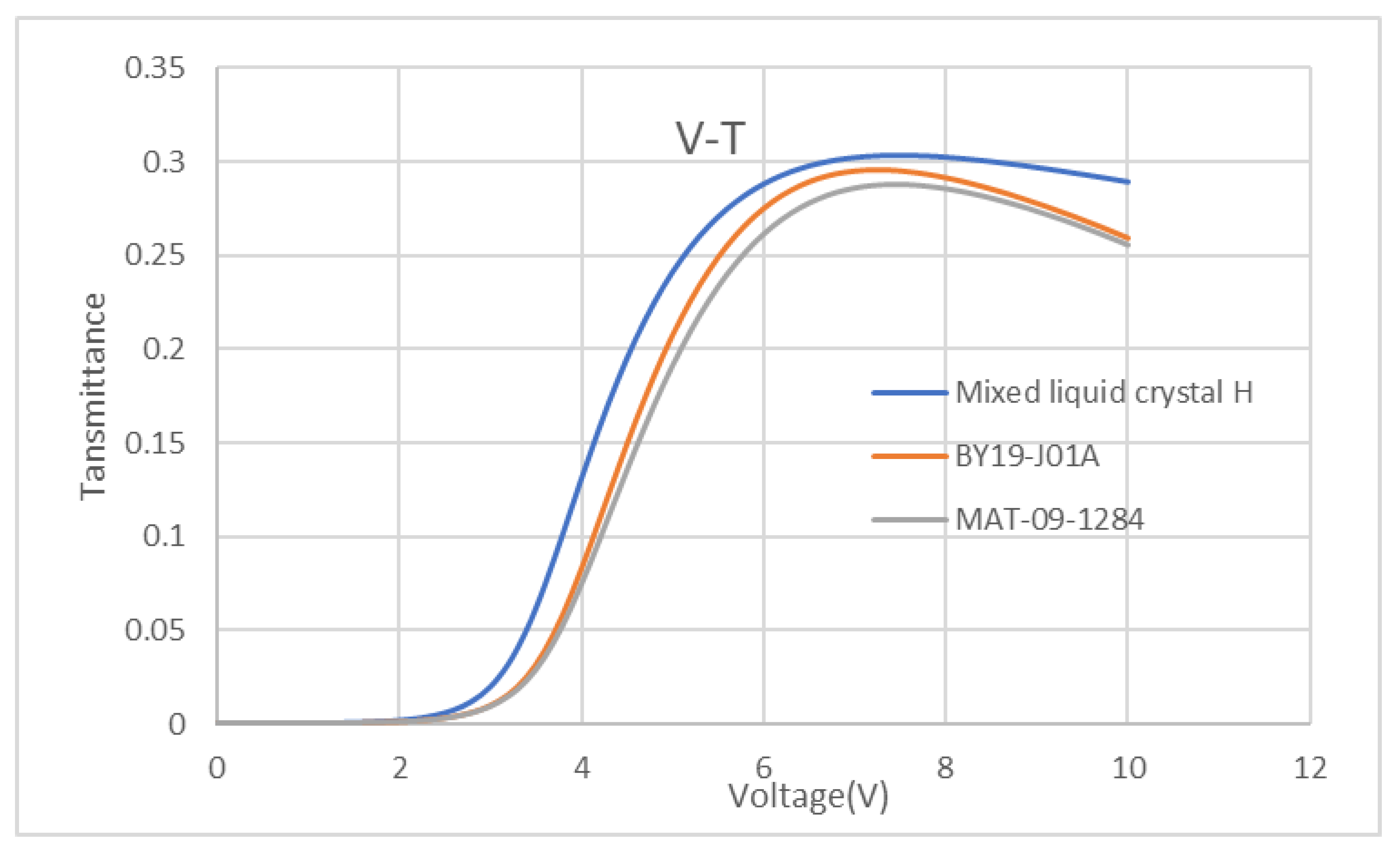
2.2. The Improvement of Response Time of Negative Dielectric Anisotropy Liquid Crystal
3. Materials & Methods
4. Conclusions
Supplementary Materials
Author Contributions
Funding
Institutional Review Board Statement
Informed Consent Statement
Data Availability Statement
Conflicts of Interest
Sample Availability
References
- Takeshi, K.; Shigeto, Y.; Akira, T.; Toshiyuki, F.; Yasuhiro, Y. Development of a novel wide-gamut 8 K 120 Hz LCD complying with ITU-R BT. SID 2015 Digest 2015, 46, 1070–1073. [Google Scholar]
- Takeshi, K.; Makoto, S.; Shinji, H.; Yasuhiro, Y.; Shigeaki, M. Development of super hi-vision 8 K × 4 K direct-view LCD for next generation TV. SID 2012 Digest 2012, 43, 780–783. [Google Scholar]
- Zhang, H.; Yunsik, I.; Liu, L.W.; Gu, H.G.; Mei, H.G.; Liao, F.; Chen, X.C.; Jungmok, J. Low power and narrow border 8 K notebook display with smart view. SID 2019 Digest 2019, 50, 818–821. [Google Scholar] [CrossRef]
- Kenichiro, M.; Yukihiro, N.; Masayuki, S.; Eisuke, N. Comparing visual realness between high resolution images and real objects. ITE Tech. Rep. 2011, 35, 133–135. [Google Scholar]
- Ma, M.H.; Tung, C.W.; Lin, Y.Z.; Lin, W.L.; Chen, C. 4-side Micro Border 8 k4 k LCD with Oxide-TFT Gate Driver Embedded Array. SID 2020 Digest 2020, 51, 1330–1333. [Google Scholar]
- Liao, Y.P.; Shao, X.B.; Yuan, J.F.; Zhang, X.Q.; Zhang, J.; Leng, Y.L.; Huang, Y.L.; Lee, S. Development of a 97.5-inch super hi-vision 8 K × 4 K liquid crystal display panel. J. Inf. Disp. 2015, 16, 137–142. [Google Scholar] [CrossRef]
- Keiji, I.; Takenobu, U.; YuKio, M.; Yasushi, M.; Masahiko, S.; Yasuyuki, N.; Takashi, F.; Tomoki, N.; Takeru, Y. Developments of a 145-inch diagonal super hi-vision plasma display panel. SID 2012 Digest 2012, 43, 71–74. [Google Scholar]
- Chen, L.Y.; Chen, X.B.; Hou, H.L.; Mo, Y.M.; Chiu, C.Y. Development of the world-wide largest 110” 4K2K 3D TFT-LCD Display. SID 2013 Digest 2013, 44, 100–103. [Google Scholar] [CrossRef]
- Hu, H.H.; Yuan, G.C.; Gu, Z.Y.; Huang, J.H.; Ning, C.; Wang, B.Q.; Qiu, Y.; Ma, X.C.; Liu, L.W.; Liu, R.; et al. High Transmittance and high charging rate 8 K 120 Hz ADS LCD TV. SID 2020 Digest 2020, 51, 885–888. [Google Scholar] [CrossRef]
- Zhang, Y.F.; Li, X.; Zhang, Y.H.; Cao, W.; Zhang, Q.; Lin, Y.L.; He, J.W.; Chiu, C.Y.; Lin, R.; Zhang, M. Pixel design solutions for transmittance improve in 8 K VA LCD. SID 2019 Digest 2019, 50, 906–909. [Google Scholar] [CrossRef]
- Wang, H.R.; Hou, K.; Yang, Y.; Dong, L.W.; Niu, H.J.; Chen, X.C. New ADS pixel design with black post spacer for 8 k application. SID 2019 Digest 2019, 50, 711–712. [Google Scholar] [CrossRef]
- Yoshihito, H.; Tetsuo, K.; Hideki, K.; Junichi, M.; Hiroyuki, O.; Hajime, I.; Tohru, D.; Takuya, M. IGZO-TFT technology for large-screen 8 K display. J. SID 2018, 26, 169–177. [Google Scholar]
- Yu, C.K.; Huang, C.R.; Lin, C.M.; Hsu, Y.L.; Cheng, H.W. 32-inch 8 K 4 K 120 HZ LCD with LTPS TFT. SID 2021 Digest 2021, 52, 1128–1131. [Google Scholar] [CrossRef]
- DaEun, P.; YoonJung, K.; YungKyung, P. Cognitive effect on image quality in full ultra-high definition (8 K). J. Inf. Disp. 2019, 21, 103–111. [Google Scholar]
- Ryutaro, O.; Takashi, N.; Junichi, M.; Daisuke, K.; Kaori, M.; Masahiro, I.; Hideki, M. Word’s Frist 55-in. 120 Hz-Driven 8 K 4 K IPS-LCD with wide color gamut. SID 2015 Digest 2015, 46, 1055–1058. [Google Scholar]
- Guo, L.; Xia, H.; Tian, Z.W.; Xiao, J.C.; Zhou, H. Fabrication and characterization of thick Cu films deposited on G8.5 LCD glass substrates for 8 K and large TV panels. SID 2020 Digest 2020, 51, 1519–1522. [Google Scholar]
- Hu, D.B.; Xiao, J.C.; Xu, H.Y.; Fei, J.Y.; Qiu, Y.Y.; Liu, Q.S.; Li, J.; Zhuang, J.Q.; Liu, C.M.; Zhang, X. AM MiniLED Local dimming backlight achieving high dynamic contras for 8 K displays. In Proceedings of the International Conference on Display Technology, Wuhan, China, 11–14 October 2020; Volume 52, pp. 290–291. [Google Scholar]
- Chang, H.O.; Hong, J.S.; Woo, J.N.; Byung, C.A.; Soo, Y.C.; Sang, D.Y. Technological Progress and Commercialization of OLED TV. SID 2013 Digest 2013, 44, 239–242. [Google Scholar]
- Detavernier, C.; Deduytsche, D.; Meirhaeghe, R.L.; Baerdemaeker, D.J.; Dauwe, C. Room-temperature grain growth in sputter-deposited Cu films. Appl. Phys. Lett. 2003, 82, 1863–1865. [Google Scholar] [CrossRef]
- Yoshiaki, S.; Yasuhito, S. Effects of viewing ultra-high-resolution images with practical viewing distances on familiar impressions. IEEE Trans. Broadcast. 2018, 64, 498–507. [Google Scholar]
- Chen, Y.; Luo, Z.Y.; Peng, F.L.; Wu, S.T. Fringe-field switching with a negative dielectric anisotropy liquid crystal. J. Disp. Technol. 2013, 9, 74–77. [Google Scholar] [CrossRef]
- Tae, Y.J.; Dae, L.P.; Ji, S.P.; Lee, J.H.; Sungho, K.; Byeong, K.K.; Kim, H.R. Switching mode for applying negative liquid crystals in high-resolution mobile dispalys. J. Disp. Technol. 2015, 11, 229–235. [Google Scholar]
- Jung, W.K.; Dong, H.S.; Ki, H.K.; Yoon, T.H. High transmittance LC mode based on fringe field switching of vertically-aligned negative LCs. SID 2013 Digest 2013, 44, 1376–1379. [Google Scholar]
- You, H.E.; Sang, S.Y.; Seung, R.P.; Joun, H.L.; Myung, C.J.; In, B.K. Novel in-plane switching (IPS) mode with high transmittance using negative dielectric liquid crystal. SID 2018 Digest 2018, 49, 1092–1094. [Google Scholar]
- Hong, J.Y.; Mi, H.J.; In, W.J.; Seung, H.L.; Seon, H.A.; Hae, J.H. Achieving high light efficiency and fast response time in fringe field switching mode using a liquid crystal with negative dielectric anisotropy. Liq. Cryst. 2012, 39, 1141–1148. [Google Scholar]
- Yang, G.Q.; Sun, Y.B. A high-transmittance vertical alignment liquid crystal display using a fringe and in-plane electrical field. Liq. Cryst. 2011, 38, 469–473. [Google Scholar] [CrossRef]
- Yang, G.Q.; Sun, Y.B. Fast-response vertical alignment liquid crystal display driven by in-plane switching. Liq. Cryst. 2011, 38, 507–510. [Google Scholar] [CrossRef]
- Joon, H.; Tae, H.C.; Jae, W.H.; Tae, H.Y. Negative liquid crystal cell with parallel patterned electrodes for high transmittance and fast switching. J. Opt. Soc. Korea 2015, 19, 260–264. [Google Scholar]
- Lin, H.T.; Wang, M.C.; Yao, Z.X.; Liu, J.R.; Wang, Z.T.; Shao, X.B. Mechanism research about flicker in TFT-LCD. Chin. J. Liq. Cryst. Disp. 2013, 28, 567–570. [Google Scholar]
- Kirkman, N.T.; Striner, T.; Hagston, W.E. Continuum modelling of hybrid-aligned nematic liquid ctystal cells: Optical response and flexoelectricity-induced voltage shift. Liq. Cryst. 2003, 30, 1115–1122. [Google Scholar] [CrossRef]
- Kim, J.W.; Choi, T.H.; Yoon, T.H.; Choi, E.J.; Lee, J.H. Elimination of image flicker in fringe-field switching liquid crystal display driven with low frequency electric field. Opt. Express 2014, 22, 30586–30591. [Google Scholar] [CrossRef]
- Hyojin, L.; Hyunggmin, K.; Jongyoon, K.; Lee, J.H. Dependence of image flickering of negative dielectric anisotropy liquid crystal on the flexoelectric coefficient ratio and the interdigitated electrode structure. J. Phys. D Appl. Phys. 2016, 49, 075501. [Google Scholar]
- Jeong, H.; Jang, I.W.; Kim, D.H.; Han, J.S.; Kumar, B.V.; Lee, S.H. Investigation on flexoelectric effect in the fringe field switching mode. SID 2013 Digest 2018, 44, 1368–1371. [Google Scholar] [CrossRef]
- Jiang, Y.F.; Zhou, X.C.; Qin, G.K.; Xu, X.G.; Lee, S.H.; Yang, D.K. Effects of flexoelectricity and ion on the flicker fringe flicker switching liquid crystal display. SID 2018 Digest 2018, 49, 1095–1098. [Google Scholar] [CrossRef]
- Chu, K.C.; Huang, C.W.; Lin, R.F.; Tsai, C.H.; Yeh, J.N.; Su, S.Y.; Ou, C.J.; Fan, S.C.; Jiang, F.; Tsai, W.C. A method for analyzing the eye strain in fringe-field-switching LCD under low-frequency driving. SID 2014 Digest 2014, 45, 308–311. [Google Scholar] [CrossRef]
- Xing, H.Y.; Ye, W.J.; Zhang, Z.D.; Xuan, L. Flexoelectric-induced voltage shift aligned nematic liquid crystal cell. Commun. Theor. Phys. 2011, 56, 939–942. [Google Scholar] [CrossRef]
- Murthy, P.R.; Raghunathan, V.A.; Madhusudana, N.V. Experimental determination of the flexoelectric coefficients of some nematic liquid crystals. Liq. Cryst. 1993, 14, 483–496. [Google Scholar] [CrossRef]
- Meyer, R.B. Piezoelectric effects in liquid crystals. Rev. Lett. 1969, 22, 918–921. [Google Scholar] [CrossRef]
- Straley, J.P. Theory of piezoelectricity in nematic liquid crystals, and of the cholesteric ordering. Phys. Rev. A 1976, 14, 1835–1841. [Google Scholar] [CrossRef]
- Seung, W.O.; Jun, H.P.; Jong, M.B.; Choi, T.H.; Yoon, T.H. Effect of electrode spacing on image flicker in fringe-field-switching liquid crystal display. Liq. Cryst. 2016, 43, 972–979. [Google Scholar]
- Harden, J.; Mbanga, B.; Eber, N.; Csorba, F.; Sprunt, S.; Gleeson, J.T.; Jakli, A. Giant flexoelectricity of bent-core nematic liquid crystals. Phys. Rev. Lett. 2006, 97, 157802. [Google Scholar] [CrossRef] [Green Version]
- Chen, H.W.; Peng, F.L.; Hu, M.G.; Wu, S.T. Flexoelectric effect and human eye perception on the image flickering of a liquid crystal display. Liq. Cryst. 2015, 42, 1730–1737. [Google Scholar] [CrossRef]
- Seung, W.O.; Jun, H.P.; Ji, H.L.; Tae, H.Y. Elimination of image flicker in a fringe-field switching liquid crystal display by applying a bipolar voltage wave. Appl. Phys. Lett. 2015, 23, 2401–24018. [Google Scholar]
- Xu, D.M.; Peng, F.L.; Tan, G.J.; He, J.; Wu, S.T. A semi-empirical equation for the response time of in-plane switching liquid crystal display and measurement of twist elastic constant. J. Appl. Phys. 2015, 117, 203103. [Google Scholar] [CrossRef] [Green Version]
- Wen, C.H.; Gauza, S.; Wu, S.T. Photostability of liquid crystals and alignment layers. J. Soc. Inf. Disp. 2005, 13, 805–810. [Google Scholar] [CrossRef]
- Yang, Q.; Zou, J.Y.; Li, Y.; Wu, S.T. Fast-response liquid crystal phase modulators with an excellent photostability. Crystals 2020, 10, 765. [Google Scholar] [CrossRef]


| Type | 2K | 4K | 8K |
|---|---|---|---|
| Transmittance (%) | 100 | 102–104 | 104–106 |
| VHR (%) | ~85 | ~90 | ~92 |
| flicker (dB) | ~−45 | ~−48 | ~−50 |
| Entry | Structure |
|---|---|
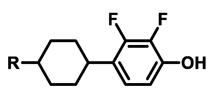
| a1 |  |
| a2 |  |
| a3 |  |
| a4 |  |
| a5 |  |
| a6 |  |
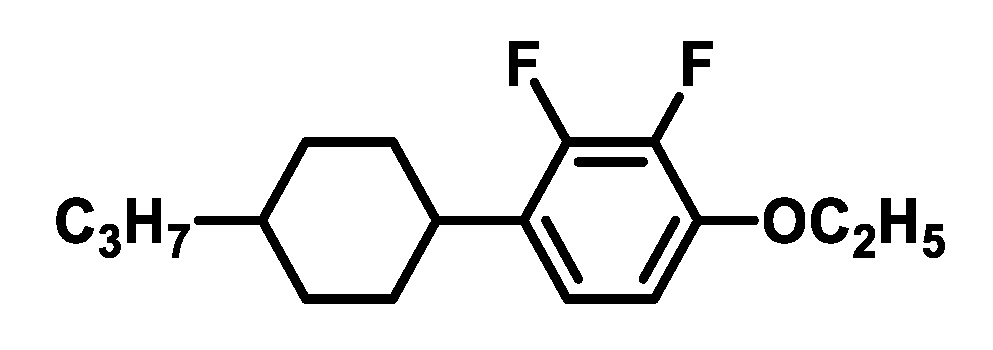
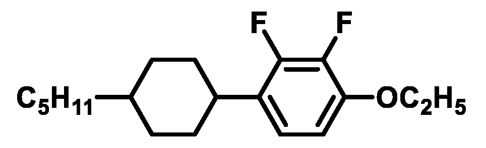
| Entry | Structure | Content (%) | Purpose |
|---|---|---|---|
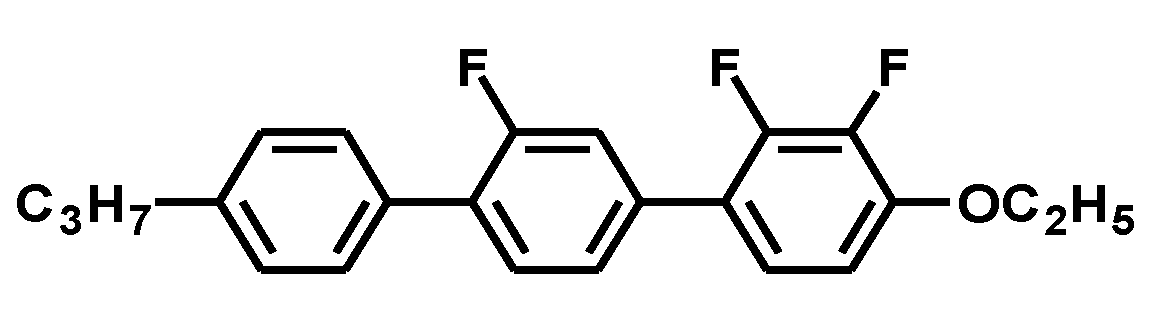
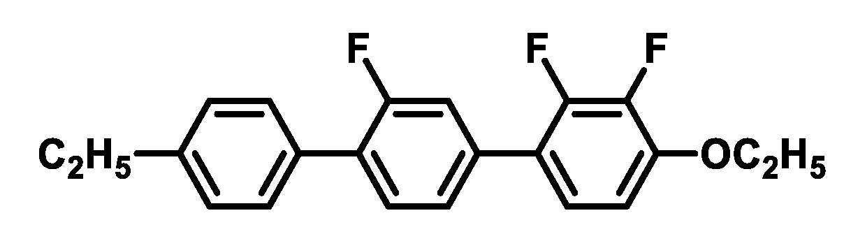
| 1 |  | 11 | Increase the Cp, Δn, and K, improve the photo-stability |
| 2 |  | 11 | Increase the Cp, Δn, and K, improve the photo-stability |
| 3 |  | 14.5 | Reduce the γ1, improve the photo-stability |
| 4 |  | 3 | Increase the Cp, Δn, and K, improve the photo-stability |
| 5 |  | 2.5 | Increase the Cp, Δn, and K, improve the photo-stability |
| 6 |  | 29.5 | Reduce the γ1, improve the mutual solubility |
| 7 |  | 10 | Reduce the γ1, increase the K |
| 8 |  | 2.5 | Reduce the γ1 |
| 9 |  | 2.0 | Reduce the γ1 |
| 10 |  | 2.0 | Reduce the γ1 |
| 11 |  | 5.0 | Improve the mutual solubility |
| 12 |  | 3.0 | Increase the Cp, Δn, and K, improve the photo-stability, and anti-flicker |
| 13 |  | 4.0 | Increase the Cp, Δn, and K, improve the photo-stability, and anti-flicker |
| Liquid Crystal Property | Mixed Liquid Crystal H | MAT-09-1284 | BY19-J01A | |
|---|---|---|---|---|
| Clear point | TNI [°C] | 74.7 | 81.4 | 81.1 |
| Phase transition temperatures | TNI [°C] | −20 | −20 | −20 |
| Dielectric anisotropy [25 °C, 1 kHz] | Δε | −2.47 | 2.62 | 2.63 |
| ε// | 3.39 | 5.22 | 6.17 | |
| ε⊥ | 5.86 | 2.60 | 3.54 | |
| Elastic constant [25 °C] | K11[pN] | 12.81 | 13.75 | 12.64 |
| K22[pN] | 6.41 | 6.88 | 6.32 | |
| K33[pN] | 14.22 | 16.14 | 14.84 | |
| Rotary Viscosity [25 °C] | γ1[mPa.s] | 53.7 | 46.6 | 48.0 |
| Optical anisotropy [589 nm, 25 °C] | ne | 1.5750 | 1.5832 | 1.5844 |
| no | 1.4817 | 1.4859 | 1.4864 | |
| Δn | 0.0956 | 0.0973 | 0.0980 | |
| Item | Mixed Liquid Crystal H | VHR/% | ION/pC |
|---|---|---|---|
| Initial | MAT-09-1284 | 87.4 | 606.9 |
| BY19-J01A | 90.1 | 464.7 | |
| Mixed liquid crystal H | 92.5 | 408.7 | |
| after UV (340 nm, 8000 mj) | MAT-09-1284 | 84.4 | 700.9 |
| BY19-J01A | 88.6 | 554.6 | |
| Mixed liquid crystal H | 89.7 | 512.8 | |
| after Heat (60 °C) & 14,000 nits BLU Aging 300 h | MAT-09-1284 | 84.2 | 691.9 |
| BY19-J01A | 87.1 | 583.1 | |
| Mixed liquid crystal H | 88.6 | 562.6 |
| Initial Flicker (dB) | 5 min Flicker (dB) | 15 min Flicker (dB) | 30 min Flicker (dB) | |
|---|---|---|---|---|
| MAT-09-1284 | −44.5 | −44.3 | −44.8 | −44.9 |
| BY19-J01A | −47.7 | −47.8 | −47.7 | −47.9 |
| Mixed liquid crystal H | −50.7 | −50.5 | −50.4 | −50.6 |
| Method | DMS | |
|---|---|---|
| Gap | 3.0 μm | |
| Response Time | MAT-09-1284 | 8.0 ms |
| BY19-J01A | 8.6 ms | |
| Mixed liquid crystal H | 9.5 ms | |
| Item | 2K | 4K | 8K | liquid Crystal H |
|---|---|---|---|---|
| Transmittance (%) | 100 | 102–104 | 104–106 | 105.5 |
| VHR (%) | ~85 | ~90 | ~92 | 92.5 |
| Flicker(dB) | ~−45 | ~−48 | ~−50 | −50.6 |
Publisher’s Note: MDPI stays neutral with regard to jurisdictional claims in published maps and institutional affiliations. |
© 2022 by the authors. Licensee MDPI, Basel, Switzerland. This article is an open access article distributed under the terms and conditions of the Creative Commons Attribution (CC BY) license (https://creativecommons.org/licenses/by/4.0/).
Share and Cite
Chen, H.; Liu, Y.; Chen, M.; Jiang, T.; Yang, Z.; Yang, H. Negative Dielectric Anisotropy Liquid Crystal with Improved Photo-Stability, Anti-Flicker, and Transmittance for 8K Display Applications. Molecules 2022, 27, 7150. https://doi.org/10.3390/molecules27217150
Chen H, Liu Y, Chen M, Jiang T, Yang Z, Yang H. Negative Dielectric Anisotropy Liquid Crystal with Improved Photo-Stability, Anti-Flicker, and Transmittance for 8K Display Applications. Molecules. 2022; 27(21):7150. https://doi.org/10.3390/molecules27217150
Chicago/Turabian StyleChen, Haiguang, Youran Liu, Maoxian Chen, Tianmeng Jiang, Zhou Yang, and Huai Yang. 2022. "Negative Dielectric Anisotropy Liquid Crystal with Improved Photo-Stability, Anti-Flicker, and Transmittance for 8K Display Applications" Molecules 27, no. 21: 7150. https://doi.org/10.3390/molecules27217150