
Sequential Processing Enables 17% All-Polymer Solar Cells via Non-Halogen Organic Solvent

Abstract
:1. Introduction
2. Experimental
2.1. Materials
2.2. Experimental Equipment and Facilities
- (1)
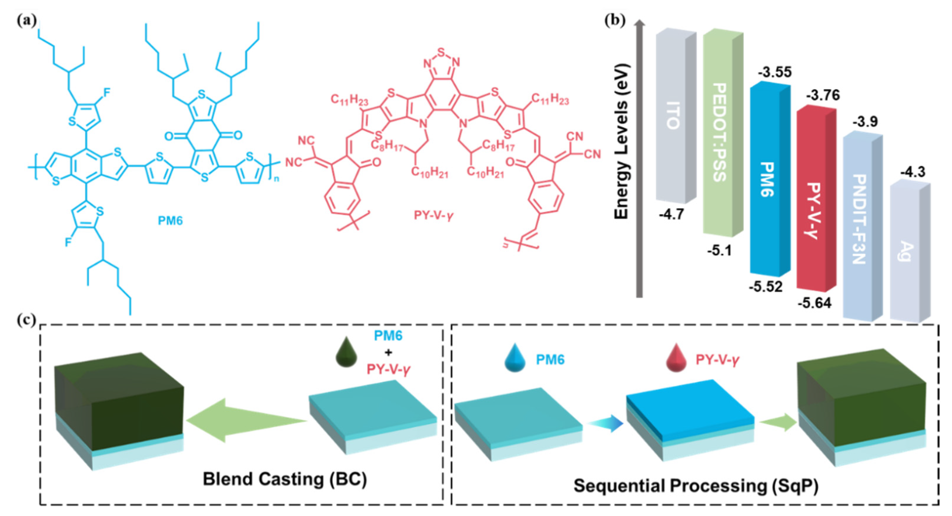
- For the blend-casting (BC) devices, namely, PM6:PY-V-γ (BC), the PM6: PY-V-γ blend (1:1.2 weight ratio) was dissolved in toluene (the concentration of donor was 7 mg mL−1 for all blends), with 1-chloronaphthalene (1% vol) as an additive and stirred overnight in a nitrogen-filled glove box. The 95 °C toluene blend solution was spin-casted at 2500 rpm for 30 s onto the PEDOT:PSS films followed by a thermal annealing of 95 °C for 5 min.
- (2)
- For the sequentially processed (SqP) device, namely, PM6/PY-V-γ (SqP), PM6 was dissolved in toluene (the concentration of donor was 8 mg mL−1); PY-V-γ was also dissolved in toluene (the concentration of donor was 12 mg mL−1) but with 1-chloronaphthalene (2% vol) as an additive. Both solutions were stirred overnight in a nitrogen-filled glove box. The donor solution was spin-casted at 4000 rpm for 30 s onto the PEDOT:PSS films, then the acceptor solution was spin-casted at 4000 rpm for 30 s onto the donor films followed by a thermal annealing of 95 °C for 5 min.
2.3. Analysis and Characterization
3. Results and Discussion
4. Conclusions
Supplementary Materials
Author Contributions
Funding
Institutional Review Board Statement
Informed Consent Statement
Data Availability Statement
Acknowledgments
Conflicts of Interest
References
- Luo, Z.; Ma, R.; Yu, J.; Liu, H.; Liu, T.; Ni, F.; Hu, J.; Zou, Y.; Zeng, A.; Su, C.J.; et al. Heteroheptacene-based acceptors with thieno [3,2-b]pyrrole yield high-performance polymer solar cells. Natl. Sci. Rev. 2022, 9, nwac076. [Google Scholar] [CrossRef] [PubMed]
- Zeng, G.; Chen, W.; Chen, X.; Hu, Y.; Chen, Y.; Zhang, B.; Chen, H.; Sun, W.; Shen, Y.; Li, Y.; et al. Realizing 17.5% Efficiency Flexible Organic Solar Cells via Atomic-Level Chemical Welding of Silver Nanowire Electrodes. J. Am. Chem. Soc. 2022, 144, 8658–8668. [Google Scholar] [CrossRef] [PubMed]
- Kan, B.; Ershad, F.; Rao, Z.Y.; Yu, C.J. Flexible organic solar cells for biomedical devices. Nano Res. 2021, 14, 2891–2903. [Google Scholar] [CrossRef]
- Song, Y.; Zhang, K.; Dong, S.; Xia, R.; Huang, F.; Cao, Y. Semitransparent Organic Solar Cells Enabled by a Sequentially Deposited Bilayer Structure. ACS Appl. Mater. Interfaces 2020, 12, 18473–18481. [Google Scholar] [CrossRef] [PubMed]
- Han, Y.W.; Jeon, S.J.; Lee, H.S.; Park, H.; Kim, K.S.; Lee, H.W.; Moon, D.K. Evaporation-Free Nonfullerene Flexible Organic Solar Cell Modules Manufactured by An All-Solution Process. Adv. Energy Mater. 2019, 9, 1902065. [Google Scholar] [CrossRef]
- Zhang, G.; Zhao, J.; Chow, P.C.Y.; Jiang, K.; Zhang, J.; Zhu, Z.; Zhang, J.; Huang, F.; Yan, H. Nonfullerene Acceptor Molecules for Bulk Heterojunction Organic Solar Cells. Chem. Rev. 2018, 118, 3447–3507. [Google Scholar] [CrossRef]
- Liu, Y.H.; Li, B.W.; Ma, C.Q.; Huang, F.; Feng, G.T.; Chen, H.Z.; Hou, J.H.; Yan, L.P.; Wei, Q.Y.; Luo, Q.; et al. Recent progress in organic solar cells (Part I material science). Sci. China Chem. 2022, 65, 224–268. [Google Scholar] [CrossRef]
- Sun, R.; Wu, Y.; Yang, X.; Gao, Y.; Chen, Z.; Li, K.; Qiao, J.; Wang, T.; Guo, J.; Liu, C.; et al. Single-Junction Organic Solar Cells with 19.17% Efficiency Enabled by Introducing One Asymmetric Guest Acceptor. Adv. Mater. 2022, 34, 2110147. [Google Scholar] [CrossRef]
- Gao, W.; Qi, F.; Peng, Z.; Lin, F.R.; Jiang, K.; Zhong, C.; Kaminsky, W.; Guan, Z.; Lee, C.-S.; Marks, T.J.; et al. Achieving 19% Power Conversion Efficiency in Planar-Mixed Heterojunction Organic Solar Cells Using a Pseudo-Symmetric Electron Acceptor. Adv. Mater. 2022, 34, 2202089. [Google Scholar] [CrossRef]
- Wu, J.; Li, G.; Fang, J.; Guo, X.; Zhu, L.; Guo, B.; Wang, Y.; Zhang, G.; Arunagiri, L.; Liu, F.; et al. Random terpolymer based on thiophene-thiazolothiazole unit enabling efficient non-fullerene organic solar cells. Nat. Commun. 2020, 11, 4612. [Google Scholar] [CrossRef]
- Ma, R.; Li, G.; Li, D.; Liu, T.; Luo, Z.; Zhang, G.; Zhang, M.; Wang, Z.; Luo, S.; Yang, T.; et al. Understanding the Effect of End Group Halogenation in Tuning Miscibility and Morphology of High-Performance Small Molecular Acceptors. Adv. Mater. 2020, 4, 2000250. [Google Scholar] [CrossRef]
- Xu, X.; Yu, L.; Meng, H.; Dai, L.; Yan, H.; Li, R.; Peng, Q. Polymer Solar Cells with 18.74% Efficiency: From Bulk Heterojunction to Interdigitated Bulk Heterojunction. Adv. Funct. Mater. 2021, 32, 2108797. [Google Scholar] [CrossRef]
- Peng, W.; Lin, Y.; Jeong, S.Y.; Genene, Z.; Magomedov, A.; Woo, H.Y.; Chen, C.; Wahyudi, W.; Tao, Q.; Deng, J.; et al. Over 18% ternary polymer solar cells enabled by a terpolymer as the third component. Nano Energy 2022, 92, 106681. [Google Scholar] [CrossRef]
- Qin, Y.; Chang, Y.; Zhu, X.; Gu, X.; Guo, L.; Zhang, Y.; Wang, Q.; Zhang, J.; Zhang, X.; Liu, X.; et al. 18.4% efficiency achieved by the cathode interface engineering in non-fullerene polymer solar cells. Nano Today 2021, 41, 101289. [Google Scholar] [CrossRef]
- Wei, Y.; Chen, Z.; Lu, G.; Yu, N.; Li, C.; Gao, J.; Gu, X.; Hao, X.; Lu, G.; Tang, Z.; et al. Binary Organic Solar Cells Breaking 19% via Manipulating Vertical Component Distribution. Adv. Mater. 2022, 34, 2204718. [Google Scholar] [CrossRef] [PubMed]
- Ma, S.; Zhang, H.; Feng, K.; Guo, X. Polymer Acceptors for High-Performance All-Polymer Solar Cells. Chemistry 2022, 28, 202200222. [Google Scholar] [CrossRef]
- Zhang, Z.G.; Li, Y. Polymerized Small-Molecule Acceptors for High-Performance All-Polymer Solar Cells. Angew. Chem. Int. Ed. 2021, 60, 4422–4433. [Google Scholar] [CrossRef]
- Zhou, K.K.; Xian, K.H.; Qi, Q.C.; Gao, M.Y.; Peng, Z.X.; Liu, J.W.; Liu, Y.; Li, S.M.; Zhang, Y.D.; Geng, Y.H.; et al. Unraveling the Correlations between Mechanical Properties, Miscibility, and Film Microstructure in All-Polymer Photovoltaic Cells. Adv. Funct. Mater. 2022, 32, 2201781. [Google Scholar] [CrossRef]
- Zhang, L.; Zhang, Z.; Deng, D.; Zhou, H.; Zhang, J.; Wei, Z. “N-π-N” Type Oligomeric Acceptor Achieves an OPV Efficiency of 18.19% with Low Energy Loss and Excellent Stability. Adv. Sci. 2022, 9, 202202513. [Google Scholar] [CrossRef]
- Yu, H.; Luo, S.W.; Sun, R.; Angunawela, I.; Qi, Z.Y.; Peng, Z.X.; Zhou, W.T.; Han, H.; Wei, R.; Pan, M.G.; et al. A Difluoro-Monobromo End Group Enables High-Performance Polymer Acceptor and Efficient All-Polymer Solar Cells Processable with Green Solvent under Ambient Condition. Adv. Funct. Mater. 2021, 31, 2100791. [Google Scholar] [CrossRef]
- Li, Y.; Li, Q.; Cai, Y.; Jin, H.; Zhang, J.; Tang, Z.; Zhang, C.; Wei, Z.; Sun, Y. Efficient polymer acceptor via random polymerization strategy enables all polymer solar cells with efficiency exceeding 17%. Energy Environ. Sci. 2022. [Google Scholar] [CrossRef]
- Wang, J.; Cui, Y.; Xu, Y.; Xian, K.; Bi, P.; Chen, Z.; Zhou, K.; Ma, L.; Zhang, T.; Yang, Y.; et al. A New Polymer Donor Enables Binary All-Polymer Organic Photovoltaic Cells with 18% Efficiency and Excellent Mechanical Robustness. Adv. Mater. 2022, 34, 2205009. [Google Scholar] [CrossRef] [PubMed]
- Yu, H.; Pan, M.; Sun, R.; Agunawela, I.; Zhang, J.; Li, Y.; Qi, Z.; Han, H.; Zou, X.; Zhou, W.; et al. Regio-Regular Polymer Acceptors Enabled by Determined Fluorination on End Groups for All-Polymer Solar Cells with 15.2% Efficiency. Angew. Chem. Int. Ed. 2021, 60, 10137–10146. [Google Scholar] [CrossRef] [PubMed]
- Sun, R.; Wang, W.; Yu, H.; Chen, Z.; Xia, X.; Shen, H.; Guo, J.; Shi, M.; Zheng, Y.; Wu, Y.; et al. Achieving over 17% efficiency of ternary all-polymer solar cells with two well-compatible polymer acceptors. Joule 2021, 5, 1548–1565. [Google Scholar] [CrossRef]
- Hawks, S.A.; Aguirre, J.C.; Schelhas, L.T.; Thompson, R.J.; Huber, R.C.; Ferreira, A.S.; Zhang, G.Y.; Herzing, A.A.; Tolbert, S.H.; Schwartz, B.J. Comparing Matched Polymer:Fullerene Solar Cells Made by Solution-Sequential Processing and Traditional Blend Casting: Nanoscale Structure and Device Performance. J. Phys. Chem. C 2014, 118, 17413–17425. [Google Scholar] [CrossRef]
- Zhang, G.Y.; Huber, R.C.; Ferreira, A.S.; Boyd, S.D.; Luscombe, C.K.; Tolbert, S.H.; Schwartz, B.J. Crystallinity Effects in Sequentially Processed and Blend-Cast Bulk-Heterojunction Polymer/Fullerene Photovoltaics. J. Phys. Chem. C 2014, 118, 18424–18435. [Google Scholar] [CrossRef]
- Dong, S.; Zhang, K.; Xie, B.M.; Xiao, J.Y.; Yip, H.L.; Yan, H.; Huang, F.; Cao, Y. High-Performance Large-Area Organic Solar Cells Enabled by Sequential Bilayer Processing via Nonhalogenated Solvents. Adv. Energy Mater. 2019, 9, 1802832. [Google Scholar] [CrossRef]
- Zhao, C.; Huang, H.; Wang, L.; Zhang, G.; Lu, G.; Yu, H.; Lu, G.; Han, Y.; Qiu, M.; Li, S.; et al. Efficient All-Polymer Solar Cells with Sequentially Processed Active Layers. Polymers 2022, 14, 2058. [Google Scholar] [CrossRef]
- Qi, Z.Y.; Yu, H.; Yu, J.W.; Zhao, H.; Zhao, C.Y.; Chen, L.; Li, C.; Ma, W.; Gao, F.; Zhang, G.Y.; et al. Blueshifting the Absorption of a Small-Molecule Donor and Using it as the Third Component to Achieve High-Efficiency Ternary Organic Solar Cells. Solar RLL 2022, 2200386. [Google Scholar] [CrossRef]
- Li, X.R.; Du, X.Y.; Zhao, J.W.; Lin, H.; Zheng, C.J.; Tao, S.L. Layer-by-Layer Solution Processing Method for Organic Solar Cells. Sol. RRL 2021, 5, 2000592. [Google Scholar] [CrossRef]
- Faure, M.D.M.; Lessard, B.H. Layer-by-layer fabrication of organic photovoltaic devices: Material selection and processing conditions. J. Mater. Chem. C 2021, 9, 14–40. [Google Scholar] [CrossRef]
- Arunagiri, L.; Zhang, G.; Hu, H.; Yao, H.; Zhang, K.; Li, Y.; Chow, P.C.Y.; Ade, H.; Yan, H. Temperature-Dependent Aggregation Donor Polymers Enable Highly Efficient Sequentially Processed Organic Photovoltaics without the Need of Orthogonal Solvents. Adv. Funct. Mater. 2019, 29, 1902478. [Google Scholar] [CrossRef]
- Bu, L.; Gao, S.; Wang, W.; Zhou, L.; Feng, S.; Chen, X.; Yu, D.; Li, S.; Lu, G. Film-Depth-Dependent Light Absorption and Charge Transport for Polymer Electronics: A Case Study on Semiconductor/Insulator Blends by Plasma Etching. Adv. Electron. Mater. 2016, 2, 1600359. [Google Scholar] [CrossRef]
- Zhang, Y.; Deng, D.; Wang, Z.; Wang, Y.; Zhang, J.; Fang, J.; Yang, Y.; Lu, G.; Ma, W.; Wei, Z. Enhancing the Photovoltaic Performance via Vertical Phase Distribution Optimization in Small Molecule:PC71BM Blends. Adv. Energy Mater. 2017, 7, 1701548. [Google Scholar] [CrossRef]
- Yu, H.; Wang, Y.; Kim, H.K.; Wu, X.; Li, Y.; Yao, Z.; Pan, M.; Zou, X.; Zhang, J.; Chen, S.; et al. A Vinylene-Linker-Based Polymer Acceptor Featuring Co-planar and Rigid Molecular Conformation Enables High-Performance All-Polymer Solar Cells. Adv. Mater. 2022, 34, 2200361. [Google Scholar] [CrossRef] [PubMed]
- Ding, S.; Ma, R.; Yang, T.; Zhang, G.; Yin, J.; Luo, Z.; Chen, K.; Miao, Z.; Liu, T.; Yan, H.; et al. Boosting the Efficiency of Non-fullerene Organic Solar Cells via a Simple Cathode Modification Method. ACS Appl. Mater. Interfaces 2021, 13, 51078–51085. [Google Scholar] [CrossRef] [PubMed]
- Kirchartz, T.; Deledalle, F.; Tuladhar, P.S.; Durrant, J.R.; Nelson, J. On the Differences between Dark and Light Ideality Factor in Polymer:Fullerene Solar Cells. J. Phys. Chem. Lett. 2013, 4, 2371–2376. [Google Scholar] [CrossRef]
- He, S.; Shen, Z.; Yu, J.; Guan, H.; Lu, G.; Xiao, T.; Yang, S.; Zou, Y.; Bu, L. Vertical Miscibility of Bulk Heterojunction Films Contributes to High Photovoltaic Performance. Adv. Mater. Interfaces 2020, 7, 2000577. [Google Scholar] [CrossRef]


| Active Layer | VOC [V] | JSC [mA/cm2] | FF | PCE (a) [%] | S(b) | nid,l(c) | μh [cm2 V−1 s−1] | μe [cm2 V−1 s−1] |
|---|---|---|---|---|---|---|---|---|
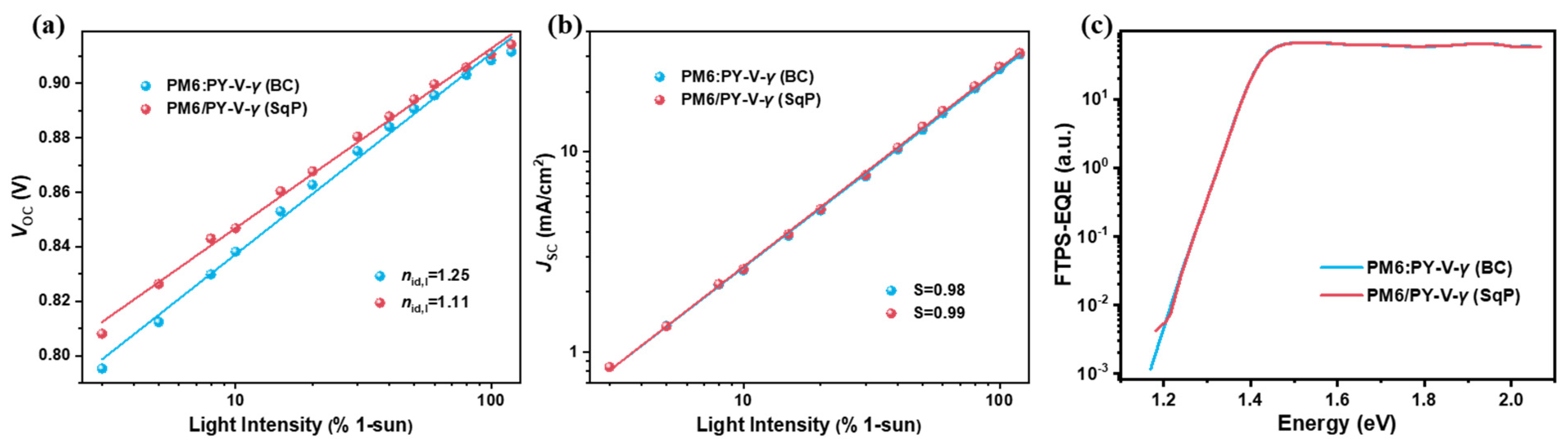
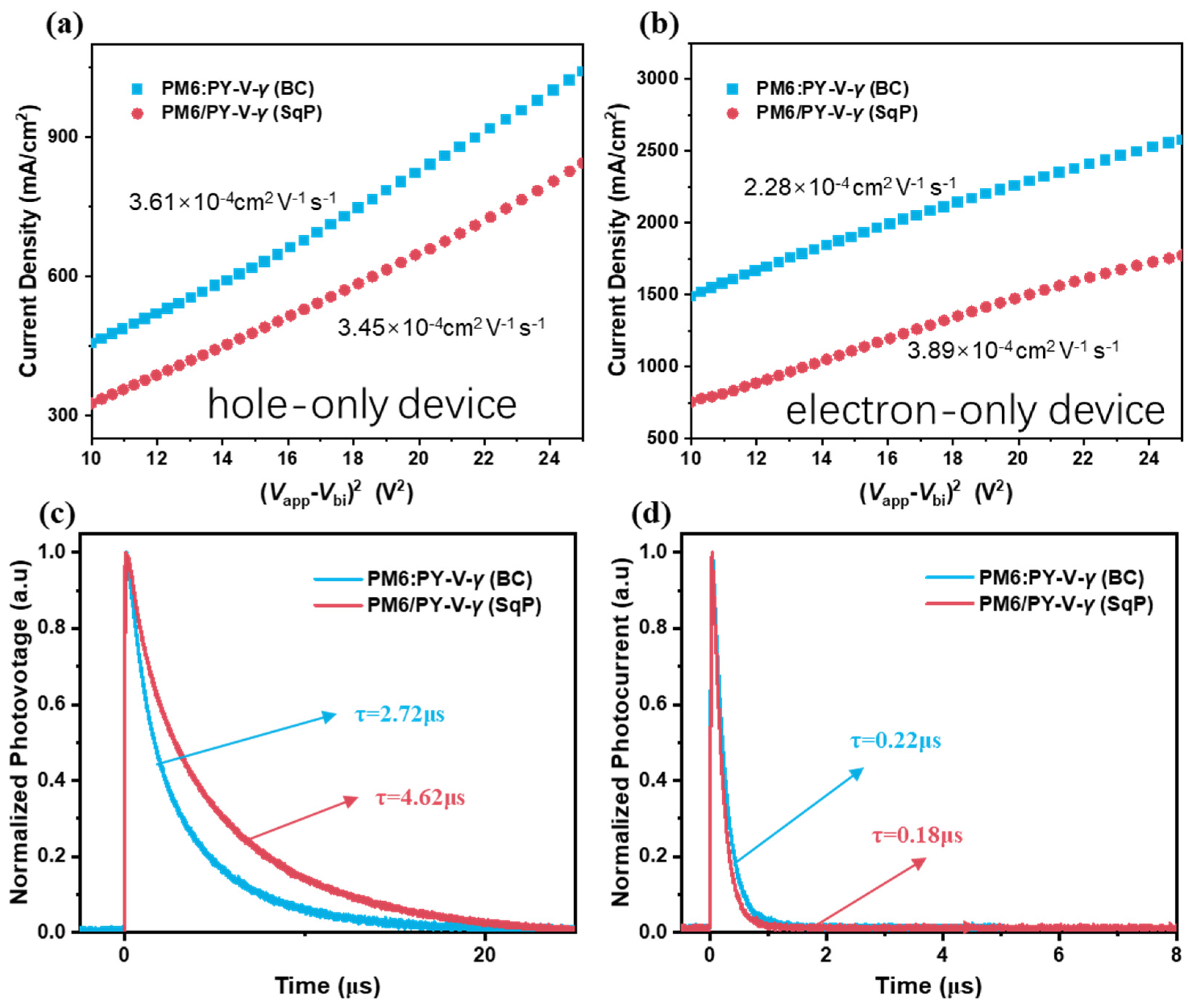
| BC | 0.909 ± 0.003 (0.913) | 24.0 ± 0.3 (24.3) | 0.737 ± 0.006 (0.733) | 16.1 ± 0.1 (16.3) | 0.983 | 1.245 | 3.61 × 10⁻⁴ | 2.28 × 10⁻⁴ |
| SqP | 0.906 ± 0.001 (0.906) | 24.3 ± 0.2 (24.5) | 0.765 ± 0.005 (0.764) | 16.8 ± 0.1 (17.0) | 0.991 | 1.114 | 3.45 × 10⁻⁴ | 3.89 × 10⁻⁴ |
Publisher’s Note: MDPI stays neutral with regard to jurisdictional claims in published maps and institutional affiliations. |
© 2022 by the authors. Licensee MDPI, Basel, Switzerland. This article is an open access article distributed under the terms and conditions of the Creative Commons Attribution (CC BY) license (https://creativecommons.org/licenses/by/4.0/).
Share and Cite
Zhao, C.; Wang, L.; Zhang, G.; Wang, Y.; Hu, R.; Huang, H.; Qiu, M.; Li, S.; Zhang, G. Sequential Processing Enables 17% All-Polymer Solar Cells via Non-Halogen Organic Solvent. Molecules 2022, 27, 5739. https://doi.org/10.3390/molecules27175739
Zhao C, Wang L, Zhang G, Wang Y, Hu R, Huang H, Qiu M, Li S, Zhang G. Sequential Processing Enables 17% All-Polymer Solar Cells via Non-Halogen Organic Solvent. Molecules. 2022; 27(17):5739. https://doi.org/10.3390/molecules27175739
Chicago/Turabian StyleZhao, Chaoyue, Lihong Wang, Guoping Zhang, Yajie Wang, Ruiyu Hu, Hui Huang, Mingxia Qiu, Shunpu Li, and Guangye Zhang. 2022. "Sequential Processing Enables 17% All-Polymer Solar Cells via Non-Halogen Organic Solvent" Molecules 27, no. 17: 5739. https://doi.org/10.3390/molecules27175739