
Sulfonate-Conjugated Polyelectrolytes as Anode Interfacial Layers in Inverted Organic Solar Cells

 ,
,  , , and
Abstract
:
1. Introduction
2. Experimental
2.1. Synthetic Methods
2.2. Device Fabrication and Photovoltaic Characterization
3. Results and Discussion
3.1. Self-Doping Behaviour
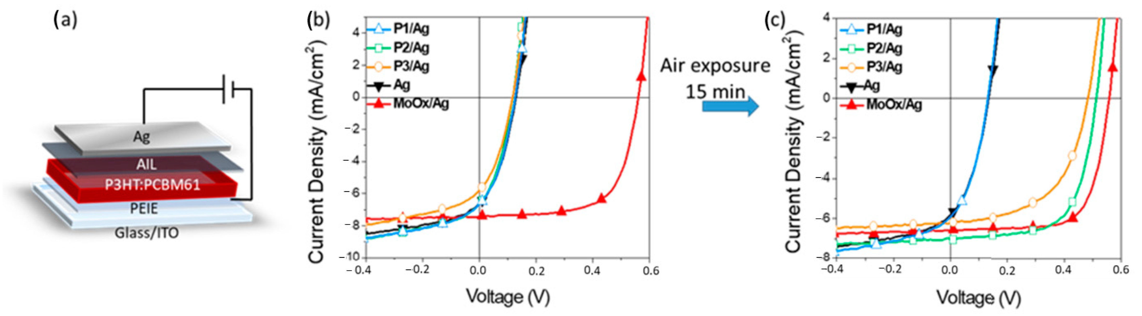
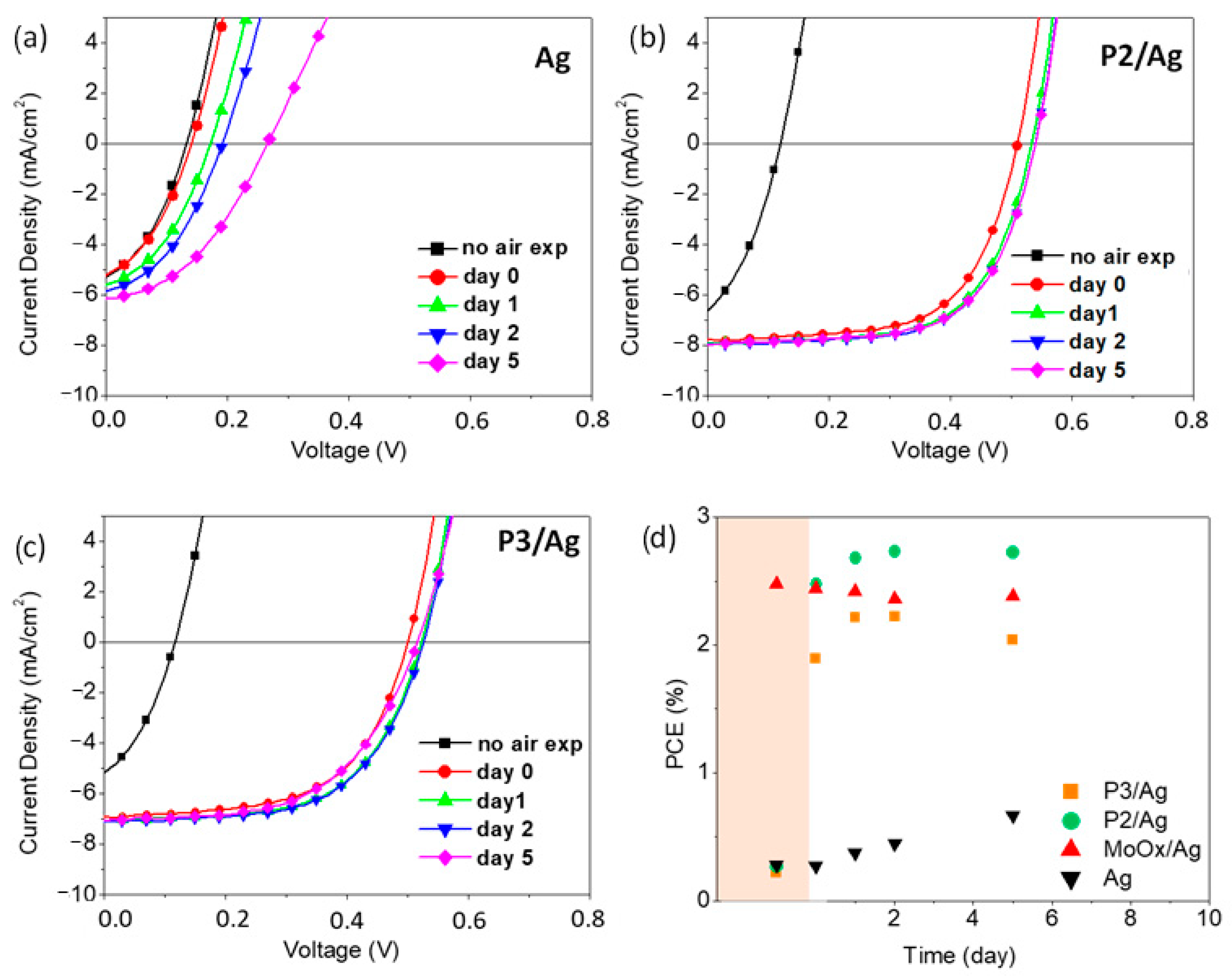
3.2. OSCs Devices Characterization
4. Conclusions
Supplementary Materials
Author Contributions
Funding
Institutional Review Board Statement
Informed Consent Statement
Data Availability Statement
Conflicts of Interest
References
- Steim, R.; Kogler, F.R.; Brabec, C.J. Interface materials for organic solar cells. J. Mater. Chem. 2010, 20, 2499–2512. [Google Scholar] [CrossRef]
- Yip, H.-L.; Jen, A.K.-Y. Recent advances in solution-processed interfacial materials for efficient and stable polymer solar cells. Energy Environ. Sci. 2012, 5, 5994–6011. [Google Scholar] [CrossRef]
- Corzo, D.; Bihar, E.; Alexandre, E.B.; Rosas-Villalva, D.; Baran, D. Ink Engineering of Transport Layers for 9.5% Efficient All-Printed Semitransparent Nonfullerene Solar Cells. Adv. Funct. Mater. 2020, 2005763. [Google Scholar] [CrossRef]
- Chueh, C.-C.; Li, C.-Z.; Jen, A.K.-Y. Recent progress and perspective in solution-processed Interfacial materials for efficient and stable polymer and organometal perovskite solar cells. Energy Environ. Sci. 2015, 8, 1160–1189. [Google Scholar] [CrossRef]
- Jiang, Y.; Peng, H.; Mai, R.; Meng, Y.; Rong, Q.; Cabanetos, C.; Nian, L.; Roncali, J.; Zhou, G.; Liu, J.; et al. Alcohol-soluble anode modifier for highly efficient inverted solar cells with oligo-oxyethylene chains. Org. Electron. 2019, 68, 200–204. [Google Scholar] [CrossRef]
- Liu, Z.; Ouyang, X.; Peng, R.; Bai, Y.; Mi, D.; Jiang, W.; Facchetti, A.; Ge, Z. Efficient polymer solar cells based on the synergy effect of a novel non-conjugated small-molecule electrolyte and polar solvent. J. Mater. Chem. A 2016, 4, 2530–2536. [Google Scholar] [CrossRef]
- Seo, J.H.; Gutacker, A.; Sun, Y.; Wu, H.-B.; Huang, F.; Cao, Y.; Scherf, U.; Heeger, A.J.; Bazan, G.C. Improved High-Efficiency Organic Solar Cells via Incorporation of a Conjugated Polyelectrolyte Interlayer. J. Am. Chem. Soc. 2011, 133, 8416–8419. [Google Scholar] [CrossRef]
- He, Z.; Zhong, C.; Su, S.; Xu, M.; Wu, H.; Cao, Y. Enhanced power-conversion efficiency in polymer solar cells using an inverted device structure. Nat. Photon. 2012, 6, 591–595. [Google Scholar] [CrossRef]
- Torimtubun, A.A.A.; Sánchez, J.G.; Pallarès, J.; Marsal, L.F. A cathode interface engineering approach for the comprehensive study of indoor performance enhancement in organic photovoltaics. Sustain. Energy Fuels 2020, 4, 3378–3387. [Google Scholar] [CrossRef]
- Nam, M.; Baek, S.; Ko, D. Unraveling optimal interfacial conditions for highly efficient and reproducible organic photovoltaics under low light levels. Appl. Surf. Sci. 2020, 526, 146632. [Google Scholar] [CrossRef]
- Oh, S.-H.; Na, S.-I.; Jo, J.; Lim, B.; Vak, D.; Kim, D.-Y. Water-Soluble Polyfluorenes as an Interfacial Layer Leading to Cathode-Independent High Performance of Organic Solar Cells. Adv. Funct. Mater. 2010, 20, 1977–1983. [Google Scholar] [CrossRef]
- He, Z.; Zhong, C.; Huang, X.; Wong, W.-Y.; Wu, H.; Chen, L.; Su, S.; Cao, Y. Simultaneous Enhancement of Open-Circuit Voltage, Short-Circuit Current Density, and Fill Factor in Polymer Solar Cells. Adv. Mater. 2011, 23, 4636–4643. [Google Scholar] [CrossRef] [PubMed]
- Lee, B.H.; Jung, I.H.; Woo, H.Y.; Shim, H.-K.; Kim, G.; Lee, K. Multi-Charged Conjugated Polyelectrolytes as a Versatile Work Function Modifier for Organic Electronic Devices. Adv. Funct. Mater. 2013, 24, 1100–1108. [Google Scholar] [CrossRef]
- Hu, L.; Wu, F.; Li, C.; Hu, A.; Hu, X.; Zhang, Y.; Chen, L.; Chen, Y. Alcohol-Soluble n-Type Conjugated Polyelectrolyte as Electron Transport Layer for Polymer Solar Cells. Macromolecules 2015, 48, 5578–5586. [Google Scholar] [CrossRef]
- Hu, Z.; Chen, Z.; Zhang, K.; Zheng, N.; Xie, R.; Liu, X.; Yang, X.; Huang, F.; Cao, Y. Self-Doped N-Type Water/Alcohol Soluble-Conjugated Polymers with Tailored Backbones and Polar Groups for Highly Efficient Polymer Solar Cells. Sol. RRL 2017, 1, 1700055. [Google Scholar] [CrossRef]
- Kesters, J.; Ghoos, T.; Penxten, H.; Drijkoningen, J.; Vangerven, T.; Lyons, D.M.; Verreet, B.; Aernouts, T.; Lutsen, L.; Vanderzande, D.; et al. Imidazolium-Substituted Polythiophenes as Efficient Electron Transport Materials Improving Photovoltaic Performance. Adv. Energy Mater. 2013, 3, 1180–1185. [Google Scholar] [CrossRef]
- Liu, Y.; Page, Z.A.; Russell, T.P.; Emrick, T. Finely Tuned Polymer Interlayers Enhance Solar Cell Efficiency. Angew. Chem. Int. Ed. 2015, 54, 11485–11489. [Google Scholar] [CrossRef]
- Carulli, F.; Scavia, G.; Lassi, E.; Pasini, M.; Galeotti, F.; Brovelli, S.; Giovanella, U.; Luzzati, S. A bifunctional conjugated polyelectrolyte for the interfacial engineering of polymer solar cells. J. Colloid Interface Sci. 2019, 538, 611–619. [Google Scholar] [CrossRef]
- Zhang, W.; Li, Y.; Zhu, L.; Liu, X.; Song, C.; Li, X.; Sun, X.; Zhang, W. A PTB7-based narrow band-gap conjugated polyelectrolyte as an efficient cathode interlayer in PTB7-based polymer solar cells. Chem. Commun. 2017, 53, 2005–2008. [Google Scholar] [CrossRef]
- Carulli, F.; Mróz, W.; Lassi, E.; Sandionigi, C.; Squeo, B.M.; Meazza, L.; Scavia, G.; Luzzati, S.; Pasini, M.; Giovanella, U.; et al. Effect of the introduction of an alcohol-soluble conjugated polyelectrolyte as cathode interlayer in solution-processed organic light-emitting diodes and photovoltaic devices. Chem. Pap. 2018, 72, 1753–1759. [Google Scholar] [CrossRef]
- Squeo, B.M.; Carulli, F.; Lassi, E.; Galeotti, F.; Giovanella, U.; Luzzati, S.; Pasini, M. Benzothiadiazole-based conjugated polyelectrolytes for interfacial engineering in optoelectronic devices. Pure Appl. Chem. 2019, 91, 477–488. [Google Scholar] [CrossRef]
- Zhou, H.; Zhang, Y.; Mai, C.-K.; Collins, S.D.; Nguyen, T.; Bazan, G.C.; Heeger, A.J. Conductive Conjugated Polyelectrolyte as Hole-Transporting Layer for Organic Bulk Heterojunction Solar Cells. Adv. Mater. 2013, 26, 780–785. [Google Scholar] [CrossRef] [PubMed]
- Lee, B.H.; Lee, J.-H.; Jeong, S.Y.; Park, S.B.; Lee, S.H.; Lee, K. Broad Work-Function Tunability of p-Type Conjugated Polyelectrolytes for Efficient Organic Solar Cells. Adv. Energy Mater. 2014, 5, 1401653. [Google Scholar] [CrossRef]
- Cui, Y.; Jia, G.; Zhu, J.; Kang, Q.; Yao, H.; Lu, L.; Xu, B.; Hou, J. The Critical Role of Anode Work Function in Non-Fullerene Organic Solar Cells Unveiled by Counterion-Size-Controlled Self-Doping Conjugated Polymers. Chem. Mater. 2018, 30, 1078–1084. [Google Scholar] [CrossRef]
- Cui, Y.; Xu, B.; Yang, B.; Yao, H.; Li, S.; Hou, J. A Novel pH Neutral Self-Doped Polymer for Anode Interfacial Layer in Efficient Polymer Solar Cells. Macromolecules 2016, 49, 8126–8133. [Google Scholar] [CrossRef]
- Jo, J.W.; Jung, J.W.; Bae, S.; Ko, M.J.; Kim, H.; Jo, W.H.; Jen, A.K.-Y.; Son, H.J. Development of Self-Doped Conjugated Polyelectrolytes with Controlled Work Functions and Application to Hole Transport Layer Materials for High-Performance Organic Solar Cells. Adv. Mater. Interfaces 2016, 3, 1500703. [Google Scholar] [CrossRef]
- Moon, S.; Khadtare, S.; Wong, M.; Han, S.-H.; Bazan, G.C.; Choi, H. Hole transport layer based on conjugated polyelectrolytes for polymer solar cells. J. Colloid Interface Sci. 2018, 518, 21–26. [Google Scholar] [CrossRef]
- Xie, Q.; Zhang, J.; Xu, H.; Liao, X.; Chen, Y.; Li, Y.; Chen, L. Self-doped polymer with fluorinated phenylene as hole transport layer for efficient polymer solar cells. Org. Electron. 2018, 61, 207–214. [Google Scholar] [CrossRef]
- Xu, H.; Zou, H.; Zhou, D.; Zeng, G.; Chen, L.; Liao, X.; Chen, Y. Printable Hole Transport Layer for 1.0 cm2 Organic Solar Cells. ACS Appl. Mater. Interfaces 2020, 12, 52028–52037. [Google Scholar] [CrossRef]
- Xu, H.; Yuan, F.; Zhou, D.; Liao, X.; Chen, L.; Chen, Y. Hole transport layers for organic solar cells: Recent progress and prospects. J. Mater. Chem. A 2020, 8, 11478–11492. [Google Scholar] [CrossRef]
- Zhou, H.; Zhang, Y.; Mai, C.-K.; Seifter, J.; Nguyen, T.; Bazan, G.C.; Heeger, A.J. Solution-Processed pH-Neutral Conjugated Polyelectrolyte Improves Interfacial Contact in Organic Solar Cells. ACS Nano 2014, 9, 371–377. [Google Scholar] [CrossRef] [PubMed]
- Choi, H.; Mai, C.-K.; Kim, H.-B.; Jeong, J.; Song, S.; Bazan, G.C.; Kim, J.Y.; Heeger, A.J. Conjugated polyelectrolyte hole transport layer for inverted-type perovskite solar cells. Nat. Commun. 2015, 6, 7348. [Google Scholar] [CrossRef] [PubMed] [Green Version]
- Patil, A.; Ikenoue, Y.; Basescu, N.; Colaneri, N.; Chen, J.; Wudl, F.; Heeger, A. Self-doped conducting polymers. Synth. Met. 1987, 20, 151–159. [Google Scholar] [CrossRef]
- Mai, C.-K.; Zhou, H.; Zhang, Y.; Henson, Z.B.; Nguyen, T.-Q.; Heeger, A.J.; Bazan, G.C. Facile Doping of Anionic Narrow-Band-Gap Conjugated Polyelectrolytes During Dialysis. Angew. Chem. Int. Ed. 2013, 52, 12874–12878. [Google Scholar] [CrossRef] [PubMed]
- Li, S.; Wan, L.; Chen, L.; Deng, C.; Tao, L.; Lu, Z.; Zhang, W.; Fang, J.; Song, W. Self-Doping a Hole-Transporting Layer Based on a Conjugated Polyelectrolyte Enables Efficient and Stable Inverted Perovskite Solar Cells. ACS Appl. Energy Mater. 2020, 3, 11724–11731. [Google Scholar] [CrossRef]
- Xu, H.; Fu, X.; Cheng, X.; Huang, L.; Zhou, D.; Chen, L.; Chen, Y. Highly and homogeneously conductive conjugated polyelectrolyte hole transport layers for efficient organic solar cells. J. Mater. Chem. A 2017, 5, 14689–14696. [Google Scholar] [CrossRef]
- Cui, Q.; Bazan, G.C. Narrow Band Gap Conjugated Polyelectrolytes. Accounts Chem. Res. 2018, 51, 202–211. [Google Scholar] [CrossRef]
- Pace, G.; Tu, G.; Fratini, E.; Massip, S.; Huck, W.T.; Baglioni, P.; Friend, R.H. Poly(9,9-dioctylfluorene)-Based Conjugated Polyelectrolyte: Extended π-Electron Conjugation Induced by Complexation with a Surfactant Zwitterion. Adv. Mater. 2010, 22, 2073–2077. [Google Scholar] [CrossRef]
- Zhu, X.; Xie, Y.; Li, X.; Qiao, X.; Wang, L.; Tu, G. Anionic conjugated polyelectrolyte–wetting properties with an emission layer and free ion migration when serving as a cathode interface layer in polymer light emitting diodes (PLEDs). J. Mater. Chem. 2012, 22, 15490. [Google Scholar] [CrossRef]
- Stay, D.; Lonergan, M.C. Varying Anionic Functional Group Density in Sulfonate-Functionalized Polyfluorenes by a One-Phase Suzuki Polycondensation. Macromolecules 2013, 46, 4361–4369. [Google Scholar] [CrossRef]
- Murugesan, V.; De Bettignies, R.; Mercier, R.; Guillerez, S.; Perrin, L. Synthesis and characterizations of benzotriazole based donor–acceptor copolymers for organic photovoltaic applications. Synth. Met. 2012, 162, 1037–1045. [Google Scholar] [CrossRef]
- Pasini, M.; Destri, S.; Porzio, W.; Botta, C.; Giovanella, U. Electroluminescent poly(fluorene-co-thiophene-S,S-dioxide): Synthesis, characterisation and structure–property relationships. J. Mater. Chem. 2003, 13, 807–813. [Google Scholar] [CrossRef]
- Tian, Y.; Kuzimenkova, M.V.; Halle, J.; Wojdyr, M.; Mendaza, A.D.D.Z.; Larsson, P.-O.; Müller, C.; Scheblykin, I.G. Molecular Weight Determination by Counting Molecules. J. Phys. Chem. Lett. 2015, 6, 923–927. [Google Scholar] [CrossRef] [PubMed]
- Iosip, M.; Destri, S.; Pasini, M.; Porzio, W.; Pernstich, K.; Batlogg, B. New dithieno [3,2-b:2′,3′-d]thiophene oligomers as promising materials for organic field-effect transistor applications. Synth. Met. 2004, 146, 251–257. [Google Scholar] [CrossRef]
- Vercelli, B.; Pasini, M.; Berlin, A.; Casado, J.; Navarrete, J.T.L.; Ortiz, R.P.; Zotti, G. Phenyl- and Thienyl-Ended Symmetric Azomethines and Azines as Model Compounds for n-Channel Organic Field-Effect Transistors: An Electrochemical and Computational Study. J. Phys. Chem. C 2014, 118, 3984–3993. [Google Scholar] [CrossRef]
- Castelli, A.; Meinardi, F.; Pasini, M.; Galeotti, F.; Pinchetti, V.; Lorenzon, M.; Manna, L.; Moreels, I.; Giovanella, U.; Brovelli, S. High-Efficiency All-Solution-Processed Light-Emitting Diodes Based on Anisotropic Colloidal Heterostructures with Polar Polymer Injecting Layers. Nano Lett. 2015, 15, 5455–5464. [Google Scholar] [CrossRef] [PubMed]
- Zalar, P.; Nguyen, T.-Q. Charge Injection Mechanism in PLEDs and Charge Transport in Conjugated Polyelectrolytes. In Conjugated Polyelectrolytes; John Wiley & Sons: Hoboken, NJ, USA, 2013; pp. 315–344. [Google Scholar]
- Cho, N.S.; Hwang, D.-H.; Lee, J.I.; Jung, B.J.; Shim, H.-K. Synthesis and Color Tuning of New Fluorene-Based Copolymers. Macromolecules 2002, 35, 1224–1228. [Google Scholar] [CrossRef]
- Prosa, M.; Benvenuti, E.; Pasini, M.; Giovanella, U.; Bolognesi, M.; Meazza, L.; Galeotti, F.; Muccini, M.; Toffanin, S. Organic Light-Emitting Transistors with Simultaneous Enhancement of Optical Power and External Quantum Efficiency via Conjugated Polar Polymer Interlayers. ACS Appl. Mater. Interfaces 2018, 10, 25580–25588. [Google Scholar] [CrossRef] [Green Version]
- Mrakic-Sposta, S.; Gussoni, M.; Montorsi, M.; Porcelli, S.; Vezzoli, A. Assessment of a Standardized ROS Production Profile in Humans by Electron Paramagnetic Resonance. Available online: https://www.hindawi.com/journals/omcl/2012/973927/ (accessed on 18 January 2021).
- Cao, D.X.; Leifert, D.; Brus, V.V.; Wong, M.S.; Phan, H.; Yurash, B.; Koch, N.; Bazan, G.C.; Nguyen, T.-Q. The importance of sulfonate to the self-doping mechanism of the water-soluble conjugated polyelectrolyte PCPDTBT-SO3K. Mater. Chem. Front. 2020, 4, 3556–3566. [Google Scholar] [CrossRef]
- Etemad, S.; Pron, A.; Heeger, A.J.; MacDiarmid, A.G.; Mele, E.J.; Rice, M.J. Infrared-active vibrational modes of charged solitons in (CH)x and (CD)x. Phys. Rev. B 1981, 23, 5137–5141. [Google Scholar] [CrossRef]
- Anderson, M.; Ramanan, C.; Fontanesi, C.; Frick, A.; Surana, S.; Cheyns, D.; Furno, M.; Keller, T.; Allard, S.; Scherf, U.; et al. Displacement of polarons by vibrational modes in doped conjugated polymers. Phys. Rev. Mater. 2017, 1, 055604. [Google Scholar] [CrossRef]
- Ohno, K.; Mandai, Y.; Matsuura, H. Vibrational spectra and molecular conformation of taurine and its related compounds. J. Mol. Struct. 1992, 268, 41–50. [Google Scholar] [CrossRef]
- Yeo, J.-S.; Kang, M.; Jung, Y.-S.; Kang, R.; Lee, S.-H.; Heo, Y.-J.; Jin, S.-H.; Kim, D.-Y.; Na, S.-I. In-depth considerations for better polyelectrolytes as interfacial materials in polymer solar cells. Nano Energy 2016, 21, 26–38. [Google Scholar] [CrossRef]
- Zhou, Y.; Fuentes-Hernandez, C.; Shim, J.; Meyer, J.; Giordano, A.J.; Li, H.; Winget, P.; Papadopoulos, T.; Cheun, H.; Kim, J.; et al. A Universal Method to Produce Low-Work Function Electrodes for Organic Electronics. Science 2012, 336, 327–332. [Google Scholar] [CrossRef]
- Giovanella, U.; Pasini, M.; Lorenzon, M.; Galeotti, F.; Lucchi, C.; Meinardi, F.; Luzzati, S.; Dubertret, B.; Brovelli, S. Efficient Solution-Processed Nanoplatelet-Based Light-Emitting Diodes with High Operational Stability in Air. Nano Lett. 2018, 18, 3441–3448. [Google Scholar] [CrossRef]
- Lloyd, M.T.; Olson, D.C.; Lu, P.; Fang, E.; Moore, D.L.; White, M.S.; Reese, M.O.; Ginley, D.S.; Hsu, J.W.P. Impact of contact evolution on the shelf life of organic solar cells. J. Mater. Chem. 2009, 19, 7638–7642. [Google Scholar] [CrossRef]
- Savva, A.; Burgués-Ceballos, I.; Papazoglou, G.; Choulis, S.A. High-Performance Inverted Organic Photovoltaics Without Hole-Selective Contact. ACS Appl. Mater. Interfaces 2015, 7, 24608–24615. [Google Scholar] [CrossRef]
- Graedel, T. Corrosion Mechanisms for Silver Exposed to the Atmosphere. J. Electrochem. Soc. 1992, 139, 1963–1970. [Google Scholar] [CrossRef]
- Yoon, Y.; Angel, J.D.; Hansen, D.C. Atmospheric Corrosion of Silver in Outdoor Environments and Modified Accelerated Corrosion Chambers. Corrosion 2016, 72, 1424–1432. [Google Scholar] [CrossRef]


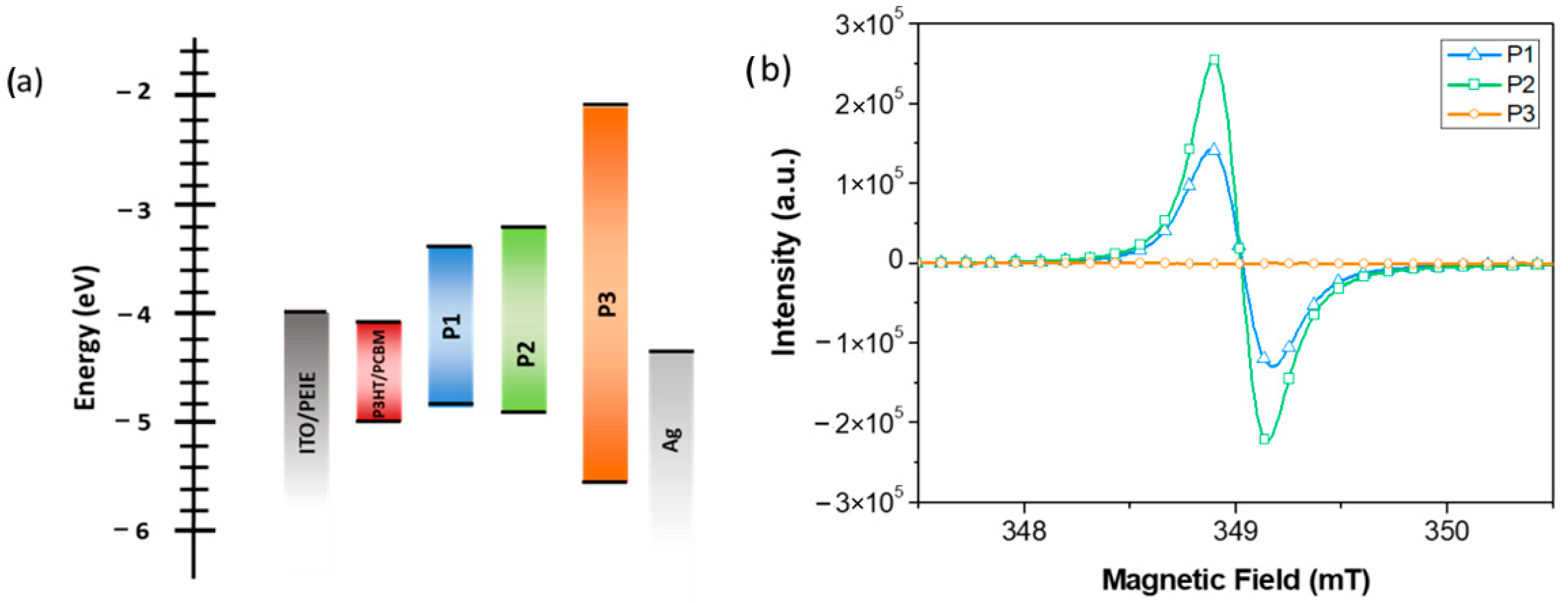
| Polymer | λmax (nm) | λonset (nm) | Eg a (eV) | HOMO (eV) | LUMO (eV) | Eg b (eV) |
|---|---|---|---|---|---|---|
| P1 | 630 | 898 | 1.38 | −4.87 | −3.31 | 1.56 |
| P2 | 719 | 947 | 1.31 | −4.83 | −3.13 | 1.50 |
| P3 | 389 | 426 | 2.91 | −5.50 | −2.2 | 3.23 |
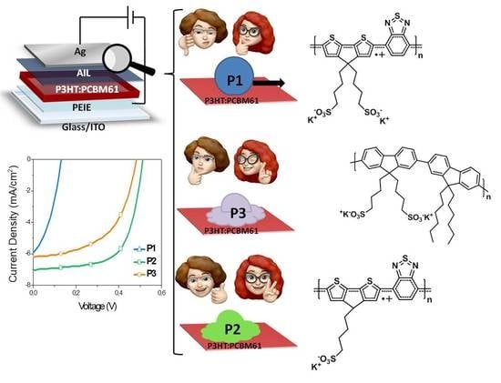
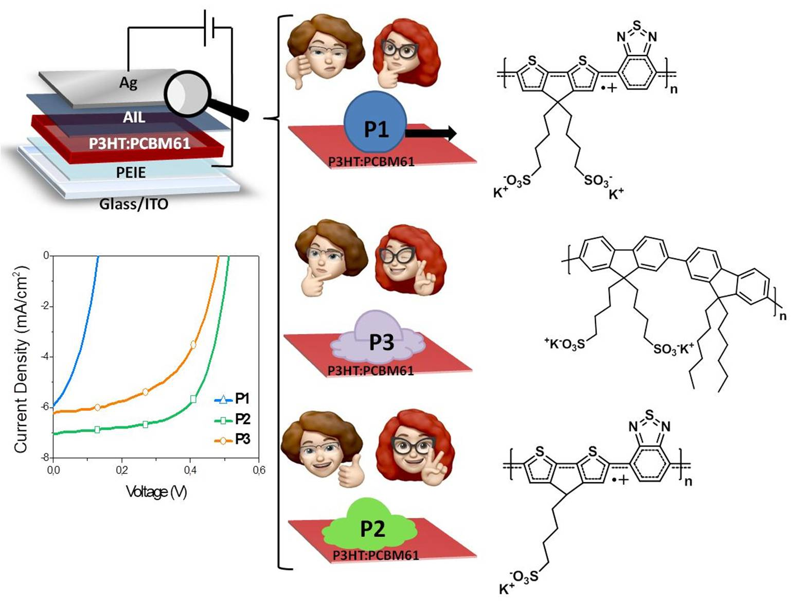
| Device | Voc (V) a | FF a | Jsc (mA/cm²) a | PCE (%) a | Rs b (Ωcm2) | Rsh c (kΩcm2) |
|---|---|---|---|---|---|---|
| Before air exposure treatment | ||||||
| Ag | 0.13 | 0.365 | 6.91 | 0.33 ± 0.01 | 9.19 | 1.70 |
| MoOx | 0.56 | 0.645 | 6.86 | 2.48 ± 0.2 | 6.85 | 123.0 |
| P1 | 0.13 | 0.356 | 6.67 | 0.31 ± 0.01 | 9.17 | 2.26 |
| P2 | 0.12 | 0.355 | 6.30 | 0.28 ± 0.01 | 8.21 | 1.37 |
| P3 | 0.12 | 0.349 | 6.20 | 0.26 ± 0.01 | 9.99 | 0.79 |
| After air exposure treatment (15 min) | ||||||
| Ag | 0.13 | 0.382 | 6.54 | 0.33 ± 0.01 | 9.86 | 1.71 |
| MoOx | 0.56 | 0.693 | 6.83 | 2.63 ± 0.12 | 6.87 | 174.9 |
| P1 | 0.13 | 0.382 | 6.64 | 0.33 ± 0.01 | 9.94 | 3.49 |
| P2 | 0.51 | 0.653 | 7.86 | 2.62 ± 0.15 | 7.20 | 31.03 |
| P3 | 0.48 | 0.527 | 7.54 | 1.90 ± 0.2 | 9.42 | 64.46 |
Sample Availability: Samples of the compounds are not available from the authors. |
Publisher’s Note: MDPI stays neutral with regard to jurisdictional claims in published maps and institutional affiliations. |
© 2021 by the authors. Licensee MDPI, Basel, Switzerland. This article is an open access article distributed under the terms and conditions of the Creative Commons Attribution (CC BY) license (http://creativecommons.org/licenses/by/4.0/).
Share and Cite
Lassi, E.; Squeo, B.M.; Sorrentino, R.; Scavia, G.; Mrakic-Sposta, S.; Gussoni, M.; Vercelli, B.; Galeotti, F.; Pasini, M.; Luzzati, S. Sulfonate-Conjugated Polyelectrolytes as Anode Interfacial Layers in Inverted Organic Solar Cells. Molecules 2021, 26, 763. https://doi.org/10.3390/molecules26030763
Lassi E, Squeo BM, Sorrentino R, Scavia G, Mrakic-Sposta S, Gussoni M, Vercelli B, Galeotti F, Pasini M, Luzzati S. Sulfonate-Conjugated Polyelectrolytes as Anode Interfacial Layers in Inverted Organic Solar Cells. Molecules. 2021; 26(3):763. https://doi.org/10.3390/molecules26030763
Chicago/Turabian StyleLassi, Elisa, Benedetta Maria Squeo, Roberto Sorrentino, Guido Scavia, Simona Mrakic-Sposta, Maristella Gussoni, Barbara Vercelli, Francesco Galeotti, Mariacecilia Pasini, and Silvia Luzzati. 2021. "Sulfonate-Conjugated Polyelectrolytes as Anode Interfacial Layers in Inverted Organic Solar Cells" Molecules 26, no. 3: 763. https://doi.org/10.3390/molecules26030763