
Effect of Hostile Solutions on the Residual Fatigue Life of Kevlar/Epoxy Composites after Impact Loading


Abstract
:1. Introduction
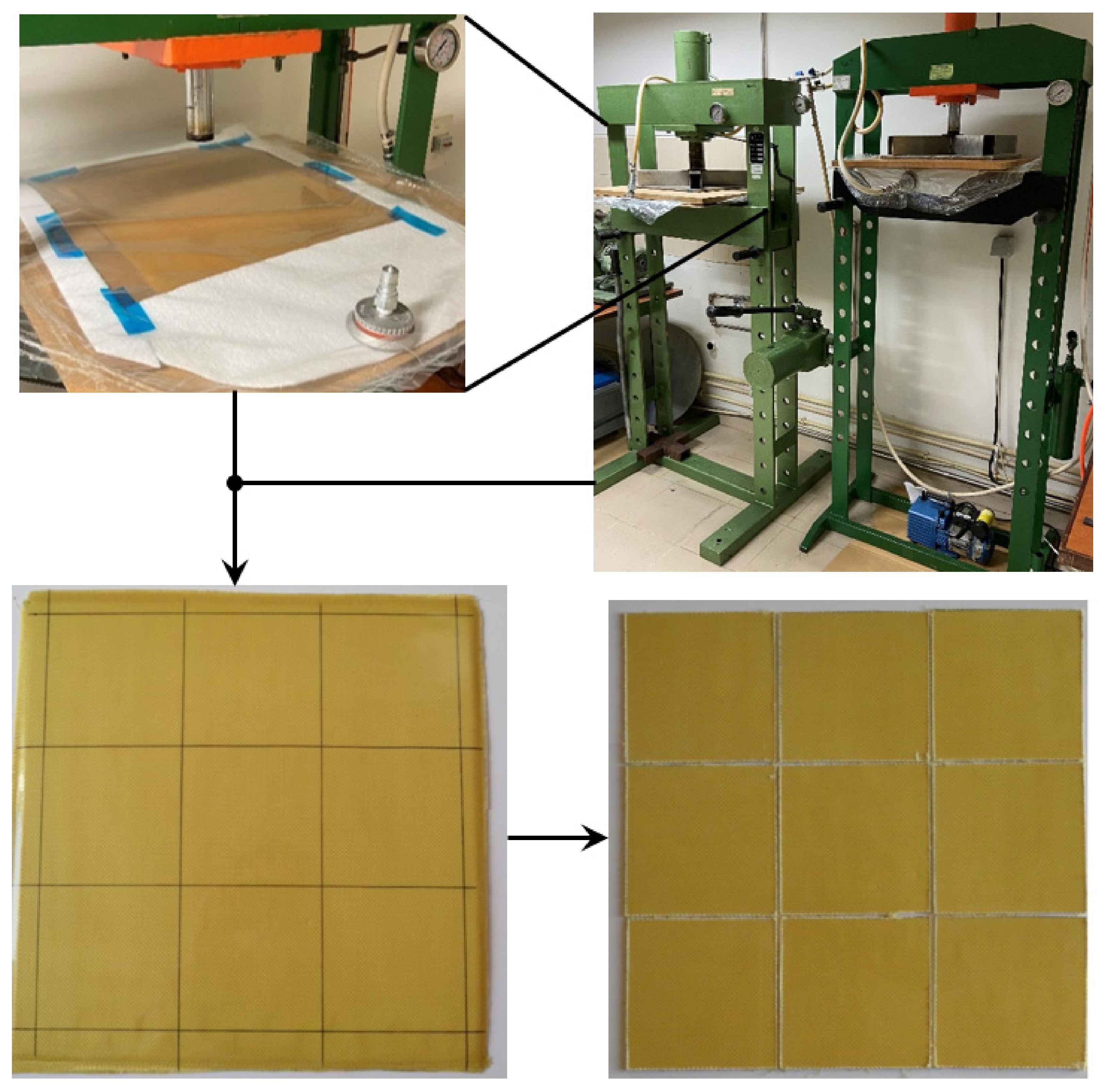
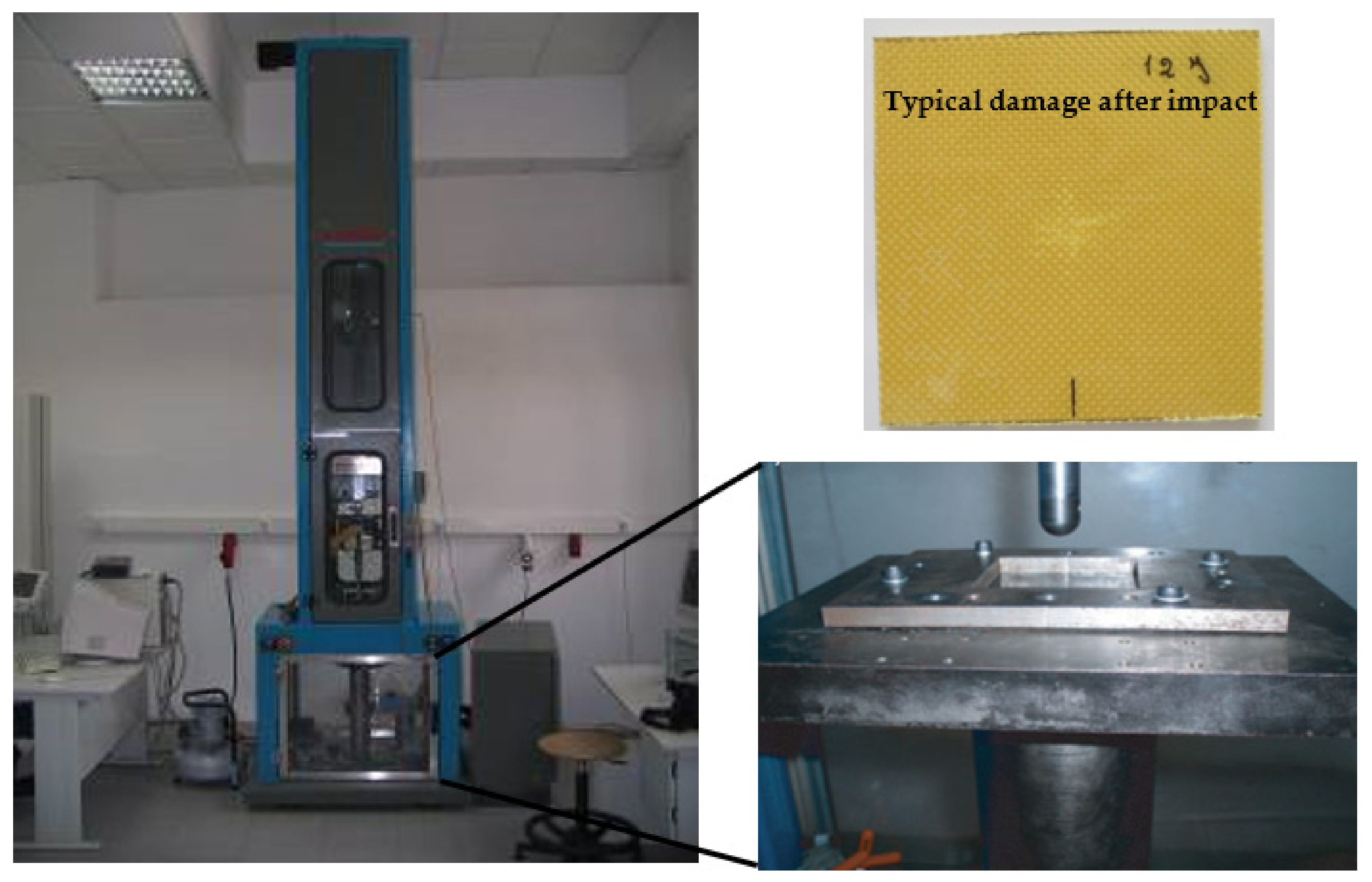
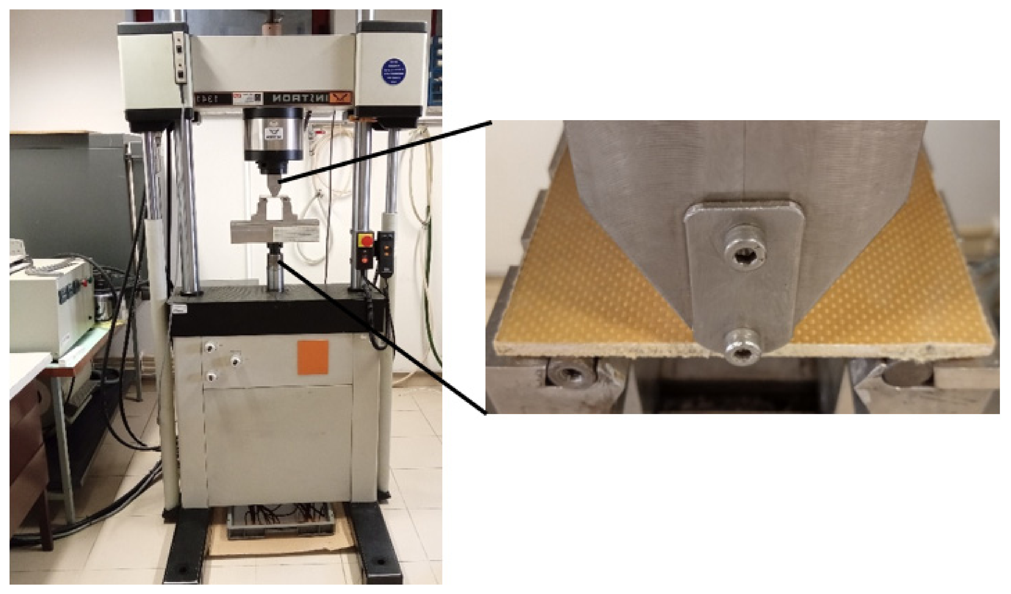
2. Materials and Methods
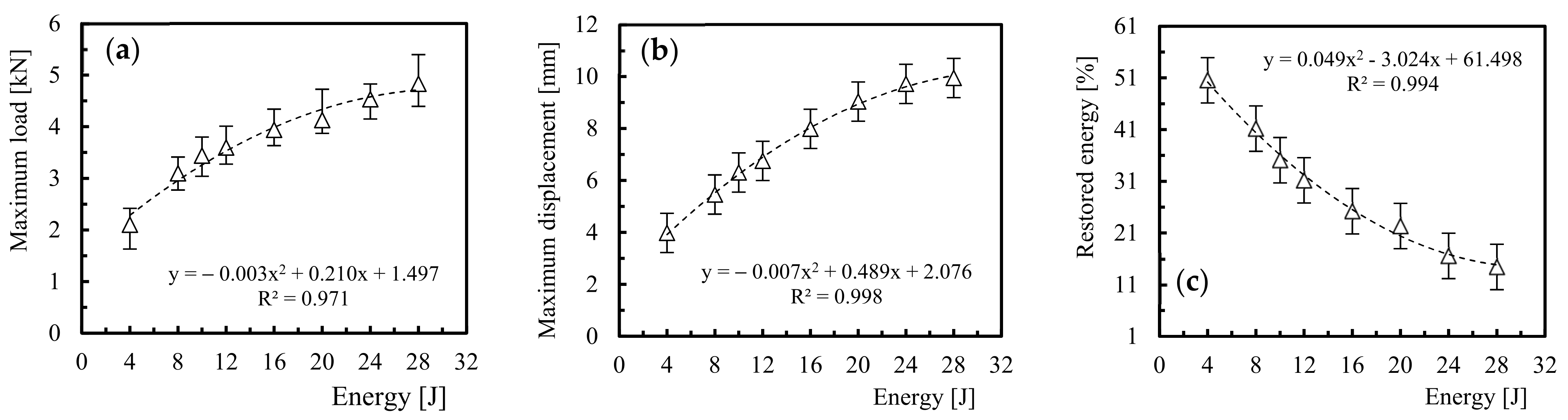
3. Results and Discussion
4. Conclusions
Author Contributions
Funding
Institutional Review Board Statement
Informed Consent Statement
Data Availability Statement
Acknowledgments
Conflicts of Interest
Sample Availability
References
- Karataş, M.A.; Gökkaya, H. A Review on Machinability of Carbon Fiber Reinforced Polymer (CFRP) and Glass Fiber Reinforced Polymer (GFRP) Composite Materials. Def. Technol. 2018, 14, 318–326. [Google Scholar] [CrossRef]
- Fakirov, S. Composite Materials—Is the Use of Proper Definitions Important? Mater. Today 2015, 18, 528–529. [Google Scholar] [CrossRef]
- Hsu, C.F.; Tsai, H.Y.; Chen, T.H. The Effect of Manufacturing Parameters and Environmental Factors on Mechanical Properties of Carbon Fiber/Epoxy Composites. J. Mech. 2018, 34, 839–846. [Google Scholar] [CrossRef]
- Reis, P.; Ferreira, J.; Zhang, Z.; Benameur, T.; Richardson, M. Impact Strength of Composites with Nano-Enhanced Resin after Fire Exposure. Compos. Part B Eng. 2014, 56, 290–295. [Google Scholar] [CrossRef] [Green Version]
- Mahmoud, M.K.; Tantawi, S.H. Effect of Strong Acids on Mechanical Properties of Glass/Polyester GRP Pipe at Normal and High Temperatures. Polym.-Plast. Technol. Eng. 2003, 42, 677–688. [Google Scholar] [CrossRef]
- Amaro, A.M.; Reis, P.N.; Neto, M.A.; Louro, C. Effects of Alkaline and Acid Solutions on Glass/Epoxy Composites. Polym. Degrad. Stab. 2013, 98, 853–862. [Google Scholar] [CrossRef]
- Amaro, A.; Reis, P.; Neto, M.A.; Louro, C. Effect of Different Acid Solutions on Glass/Epoxy Composites. J. Reinf. Plast. Compos. 2013, 32, 1018–1029. [Google Scholar] [CrossRef]
- Hogg, P.J. Factors Affecting the Stress Corrosion of GRP in Acid Environments. Composites 1983, 14, 254–261. [Google Scholar] [CrossRef]
- Jones, F.; Rock, J.; Wheatley, A. Stress Corrosion Cracking and Its Implications for the Long-Term Durability of E-Glass Fibre Composites. Composites 1983, 14, 262–269. [Google Scholar] [CrossRef]
- Norwood, L.S.; Hogg, P.J. GRP in Contact with Acidic Environments-a Case Study. Compos. Struct. 1984, 2, 1–22. [Google Scholar] [CrossRef]
- Tanaka, H.; Kuraoka, K.; Yamanaka, H.; Yazawa, T. Development and Disappearance of Microporous Structure in Acid Treated E-Glass Fiber. J. Non. Cryst. Solids 1997, 215, 262–270. [Google Scholar] [CrossRef]
- Kawada, H.; Srivastava, V.K. The Effect of an Acidic Stress Environment on the Stress-Intensity Factor for GRP Laminates. Compos. Sci. Technol. 2001, 61, 1109–1114. [Google Scholar] [CrossRef]
- Banna, M.; Shirokoff, J.; Molgaard, J. Effects of Two Aqueous Acidic Solutions on Polyester and Bisphenol A Epoxy Vinyl Ester Resins. Mater. Sci. Eng. A 2011, 528, 2137–2142. [Google Scholar] [CrossRef]
- Mohammadi, R.; Saeedifar, M.; Toudeshky, H.H.; Najafabadi, M.A.; Fotouhi, M. Prediction of Delamination Growth in Carbon/Epoxy Composites Using a Novel Acoustic Emission-Based Approach. J. Reinf. Plast. Compos. 2015, 34, 868–878. [Google Scholar] [CrossRef]
- Saeedifar, M.; Fotouhi, M.; Najafabadi, M.A.; Toudeshky, H.H. Interlaminar Fracture Toughness Evaluation in Glass/Epoxy Composites Using Acoustic Emission and Finite Element Methods. J. Mater. Eng. Perform. 2015, 24, 373–384. [Google Scholar] [CrossRef]
- Yousefi, J.; Mohamadi, R.; Saeedifar, M.; Ahmadi, M.; Hosseini-Toudeshky, H. Delamination Characterization in Composite Laminates Using Acoustic Emission Features, Micro Visualization and Finite Element Modeling. J. Compos. Mater. 2016, 50, 3133–3145. [Google Scholar] [CrossRef]
- Malpot, A.; Touchard, F.; Bergamo, S. An Investigation of the Influence of Moisture on Fatigue Damage Mechanisms in a Woven Glass-Fibre-Reinforced PA66 Composite Using Acoustic Emission and Infrared Thermography. Compos. Part B Eng. 2017, 130, 11–20. [Google Scholar] [CrossRef]
- Roundi, W.; EL Mahi, A.; El Gharad, A.; Rebière, J.-L. Acoustic Emission Monitoring of Damage Progression in Glass/Epoxy Composites during Static and Fatigue Tensile Tests. Appl. Acoust. 2018, 132, 124–134. [Google Scholar] [CrossRef]
- Saeedifar, M.; Najafabadi, M.A.; Zarouchas, D.; Toudeshky, H.H.; Jalalvand, M. Clustering of Interlaminar and Intralaminar Damages in Laminated Composites under Indentation Loading Using Acoustic Emission. Compos. Part B Eng. 2018, 144, 206–219. [Google Scholar] [CrossRef] [Green Version]
- Yousefi, J.; Najfabadi, M.A.; Toudeshky, H.H.; Akhlaghi, M. Damage Evaluation of Laminated Composite Material Using a New Acoustic Emission Lamb-Based and Finite Element Techniques. Appl. Compos. Mater. 2018, 25, 1021–1040. [Google Scholar] [CrossRef]
- Richardson, M.O.W.; Wisheart, M.J. Review of Low-Velocity Impact Properties of Composite Materials. Compos. Part A Appl. Sci. Manuf. 1996, 27, 1123–1131. [Google Scholar] [CrossRef]
- Amaro, A.M.; Reis, P.N.B.; De Moura, M.F.S.F.; Santos, J. Damage Detection on Laminated Composite Materials Using Several NDT Techniques. Insight—Non-Destructive Test. Cond. Monit. 2012, 54, 14–20. [Google Scholar] [CrossRef]
- Davies, G.; Hitchings, D.; Zhou, G. Impact Damage and Residual Strengths of Woven Fabric Glass/Polyester Laminates. Compos. Part A Appl. Sci. Manuf. 1996, 27, 1147–1156. [Google Scholar] [CrossRef]
- de Moura, M.F.S.F.; Marques, A.T. Prediction of Low Velocity Impact Damage in Carbon-Epoxy Laminates. Compos.-Part A Appl. Sci. Manuf. 2002, 33, 361–368. [Google Scholar] [CrossRef]
- Reis, P.; Ferreira, J.; Antunes, F.; Richardson, M. Effect of Interlayer Delamination on Mechanical Behavior of Carbon/Epoxy Laminates. J. Compos. Mater. 2009, 43, 2609–2621. [Google Scholar] [CrossRef]
- Amaro, A.M.; Reis, P.N.B.; De Moura, M.F.S.F. Delamination Effect on Bending Behaviour in Carbon-Epoxy Composites. Strain 2011, 47, 203–208. [Google Scholar] [CrossRef]
- Mortas, N.; Er, O.; Reis, P.; Ferreira, J. Effect of Corrosive Solutions on Composites Laminates Subjected to Low Velocity Impact Loading. Compos. Struct. 2014, 108, 205–211. [Google Scholar] [CrossRef]
- Ding, Y.Q.; Yan, Y.; McIlhagger, R. Effect of impact and fatigue loads on the strength of plain weave carbon-epoxy composites. J. Mater. Process. Tech. 1995, 55, 58–62. [Google Scholar] [CrossRef]
- Padaki, N.V.; Alagirusamy, R.; Deopura, B.L.; Sugun, B.S.; Fangueiro, R. Low velocity impact behaviour of textile reinforced composites. Ind. J. Fibre Text. Res. 2008, 33, 189–202. [Google Scholar]
- Reis, P.; Ferreira, J.; Santos, P.; Richardson, M.; Santos, J. Impact Response of Kevlar Composites with Filled Epoxy Matrix. Compos. Struct. 2012, 94, 3520–3528. [Google Scholar] [CrossRef]
- Chen, A.S.; Almond, D.P.; Harris, B. Impact damage growth in composites under fatigue conditions monitored by acoustography. Int. J. Fatigue 2002, 24, 257–261. [Google Scholar] [CrossRef]
- Melin, L.G.; Schon, J.; Nyman, T. Fatigue testing and buckling characteristics of impacted composite specimens. Int. J. Fatigue 2002, 24, 263–272. [Google Scholar] [CrossRef]
- Katerelos, D.G.; Paipetis, A.; Kostopoulos, V. A simple model for the prediction of the fatigue delamination growth of impacted composite panels. Fatigue Fract. Eng. Mater. Struct. 2004, 27, 911–922. [Google Scholar] [CrossRef]
- Butler, R.; Almond, D.P.; Hunt, G.W.; Hu, B.; Gathercole, N. Compressive fatigue limit of impact damaged composite laminates. Compos. Part A Appl. Sci. Manuf. 2007, 38, 1211–1215. [Google Scholar] [CrossRef]
- Tai, N.H.; Yip, M.C.; Lin, J.L. Effects of low-energy impact on the fatigue behavior of carbon/epoxy composites. Compos. Sci. Technol. 1998, 58, 1–8. [Google Scholar] [CrossRef]
- Amaro, A.; Reis, P.; de Moura, M.; Neto, M. Influence of Multi-Impacts on GFRP Composites Laminates. Compos. Part B Eng. 2013, 52, 93–99. [Google Scholar] [CrossRef]
- Caprino, G. Residual Strength Prediction of Impacted CFRP Laminates. J. Compos. Mater. 1984, 18, 508–518. [Google Scholar] [CrossRef]
- Adams, R.D.; Cawley, P. A Review of Defect Types and Nondestructive Testing Techniques for Composites and Bonded Joints. NDT Int. 1988, 21, 208–222. [Google Scholar] [CrossRef]
- Rubino, F.; Nisticò, A.; Tucci, F.; Carlone, P. Marine Application of Fiber Reinforced Composites: A Review. J. Mar. Sci. Eng. 2020, 8, 26. [Google Scholar] [CrossRef] [Green Version]
- Kumarasamy, S.; Mazlan, N.M.; Abidin, M.S.Z.; Anjang, A. Influence of Fuel Absorption on the Mechanical Properties of Glass-Fiber-Reinforced Epoxy Laminates. J. King Saud Univ. Eng. Sci. 2020, 32, 548–554. [Google Scholar] [CrossRef]
- Silva, M.A.G.; Fonseca, B.S.; Biscaia, H. On estimates of durability of FRP based on accelerated tests. Compos. Struct. 2014, 116, 377–387. [Google Scholar] [CrossRef]
- Einde, L.V.D.; Zhao, L.; Seible, F. Use of FRP composites in civil structural applications. Constr. Build Mater. 2003, 17, 389–403. [Google Scholar] [CrossRef]
- Griffiths, R.; Ball, A. An assessment of the properties and degradation behaviour of glass-fibre-reinforced polyester polymer concrete. Compos. Sci. Technol. 2000, 60, 2747–2753. [Google Scholar] [CrossRef]
- Mallinson, J.H. Corrosion-Resistant Plastic Composites in Chemical Plant Design; Marcel Dekker, Inc.: New York, NY, USA, 1988. [Google Scholar]
- Amaro, A.M.; Reis, P.N.B.; Magalhães, A.; De Moura, M.F.S.F. The Influence of the Boundary Conditions on Low-Velocity Impact Composite Damage. Strain 2011, 47, e220–e226. [Google Scholar] [CrossRef]
- Schoeppner, G.A.; Abrate, S. Delamination threshold loads for low velocity impact on composite laminates. Compos. Part A Appl. Sci. Manuf. 2000, 31, 903–915. [Google Scholar] [CrossRef]
- Reis, P.N.B.; Ferreira, J.A.M.; Zhang, Z.Y.; Benameur, T.; Richardson, M.O.W. Impact response of Kevlar composites with nanoclay enhanced epoxy matrix. Compos. Part B -Eng. 2013, 46, 7–14. [Google Scholar] [CrossRef]
- Reis, P.; Santos, P.; Ferreira, J.; Richardson, M. Impact Response of Sandwich Composites with Nano-Enhanced Epoxy Resin. J. Reinf. Plast. Compos. 2013, 32, 898–906. [Google Scholar] [CrossRef]
- Hosur, M.V.; Chowdhury, F.; Jeelani, S. Low-Velocity Impact Response and Ultrasonic NDE of Woven Carbon/Epoxy-Nanoclay Nanocomposites. J. Compos. Mater. 2007, 41, 2195–2212. [Google Scholar] [CrossRef]
- Gustin, J.; Joneson, A.; Mahinfalah, M.; Stone, J. Low Velocity Impact of Combination Kevlar/Carbon Fiber Sandwich Composites. Compos. Struct. 2005, 69, 396–406. [Google Scholar] [CrossRef]
- Arun, K.; Basavarajappa, S.; Sherigara, B. Damage Characterisation of Glass/Textile Fabric Polymer Hybrid Composites in Sea Water Environment. Mater. Des. 2010, 31, 930–939. [Google Scholar] [CrossRef]
- Stamenović, M.; Putić, S.; Rakin, M.; Medjo, B.; Čikara, D. Effect of Alkaline and Acidic Solutions on the Tensile Properties of Glass-Polyester Pipes. Mater. Des. 2011, 32, 2456–2461. [Google Scholar] [CrossRef]
- Pavan, A.; Dayananda, P.; Vijaya, K.M.; Hegde, S.; Hosagade, P.N. Influence of seawater absorption on vibrational and tensile characteristics of quasi-isotropic glass/epoxy composites. J. Mater. Res. Technol. 2019, 8, 1427–1433. [Google Scholar] [CrossRef]
- Gargano, A.; Pingkarawat, K.; Pickerd, V.; Delaney, T.; Das, R.; Mouritz, A. Effect of seawater immersion on the explosive blast response of a carbon fi bre-polymer laminate. Compos. Part A Appl. Sci. Manuf. 2018, 109, 382–391. [Google Scholar] [CrossRef]
- Tual, N.; Carrere, N. Characterization of sea water ageing effects on mechanical properties of carbon/epoxy composites for tidal turbine blades. Compos. Part A Appl. Sci. Manuf. 2015, 78, 380–389. [Google Scholar] [CrossRef] [Green Version]
- Kafodya, I.; Xian, G.; Li, H. Durability study of pultruded CFRP plates immersed in water and seawater under sustained bending: Water uptake and effects on the mechanical properties. Compos. B. Eng. 2015, 70, 138–148. [Google Scholar] [CrossRef]
- Boisseau, A.; Peyrac, C. Long term durability of composites in marine environment: Comparative study of fatigue behavior. Procedia Eng. 2015, 133, 535–544. [Google Scholar] [CrossRef] [Green Version]
- Kumar, D.; Kumar, R. Improvement of mechanical properties of hybrid composites through interply rearrangement of glass and carbon woven fabrics for marine application. Compos. B. Eng. 2019, 168, 467–475. [Google Scholar] [CrossRef]
- David-West, O.S.; Nash, D.H.; Banks, W.M. An experimental study of damage accumulation in balanced CFRP laminates due to repeated impact. Compos. Struct. 2008, 83, 247–258. [Google Scholar] [CrossRef]
- Ferreira, J.; Reis, P.; Costa, J.; Richardson, M. Fatigue Behaviour of Kevlar Composites with Nanoclay-Filled Epoxy Resin. J. Compos. Mater. 2013, 47, 1885–1895. [Google Scholar] [CrossRef]
- Reis, P.N.B.; Ferreira, J.; Costa, J.; Santos, M. Fatigue Performance of Kevlar/Epoxy Composites with Filled Matrix by Cork Powder. Fibers Polym. 2012, 13, 1292–1299. [Google Scholar] [CrossRef]
- Olivier, P.; Cottu, J.P.; Ferret, B. Effects of cure cycle pressure and voids on some mechanical properties of carbon/epoxy laminates. Composites 1995, 26, 509–515. [Google Scholar] [CrossRef]
- Almeida, S.F.M.; Neto, Z.S.N. Effect of void content on the strength of composite laminates. Compos: Struct. 1994, 28, 139–148. [Google Scholar] [CrossRef]
- Wisnom, M.R.; Reynolds, T.; Gwilliam, N. Reduction in interlaminar shear strength by discrete and distributed voids. Compos. Sci. Technol. 1996, 56, 93–101. [Google Scholar] [CrossRef]
- Jeong, H. Effects of voids on the mechanical strength and ultrasonic attenuation of laminated composites. J. Compos. Mater. 1997, 31, 276–292. [Google Scholar] [CrossRef]
- Hahn, H.T.; Kim, R.Y. Fatigue behaviour of composite laminate. J. Compos. Mater. 1976, 10, 156–180. [Google Scholar] [CrossRef]
- Joseph, E.; Perreux, D. Fatigue behaviour of glass-fibre/epoxy-matrix filament-wound pipes: Tension loading tests and results. Compos. Sci. Technol. 1994, 52, 469–480. [Google Scholar] [CrossRef]
- Ferreira, J.A.M.; Costa, J.D.M.; Reis, P.N.B. Static and Fatigue behaviour of glass-fibre-reinforced polypropylene composites. Theor. Appl. Fract. Mech. 1999, 31, 67–74. [Google Scholar] [CrossRef] [Green Version]
- Ferreira, J.; Costa, J.; Reis, P.; Richardson, M. Analysis of fatigue and damage in glass-fibre-reinforced polypropylene composite materials. Compos. Sci. Technol. 1999, 59, 1461–1467. [Google Scholar] [CrossRef] [Green Version]
- Reis, P.N.B.; Ferreira, J.A.M.; Richardson, M.O.W. Fatigue damage characterization by NDT in polypropylene/glass fibre composites. Appl. Compos. Mater. 2011, 18, 409–419. [Google Scholar] [CrossRef]


| Solutions | Immersion Time (days) |
|---|---|
| Diesel | 15, 30, and 45 |
| Sulphuric acid (H2SO4) | 10, 20, and 30 |
| Hydrochloric acid (HCl) | 10, 20, and 30 |
| Sodium hydroxide (NaOH) | 10, 20, and 30 |
| Distilled water | 15, 30, 60, and 90 |
| Sea water at room temperature | 15, 30, 60, and 90 |
| Solutions | Restored Energy [%] | Decease Compared to Control Samples [%] |
|---|---|---|
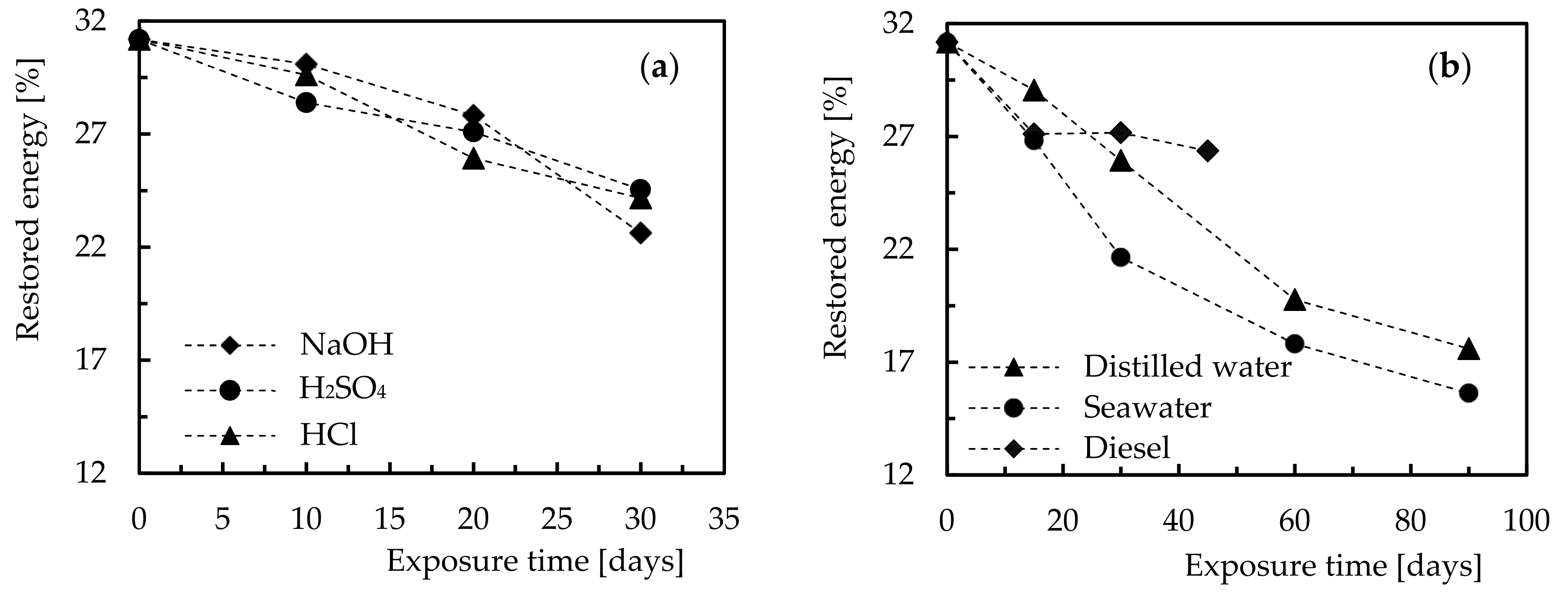
| Control samples (not immersed) | 31.2 (4.8) | - |
| Diesel | 27.2 (2.6) | 12.8 |
| Sulphuric acid (H2SO4) | 24.7 (3.0) | 20.8 |
| Hydrochloric acid (HCl) | 24.0 (2.8) | 23.1 |
| Sodium hydroxide (NaOH) | 22.6 (3.3) | 27.6 |
| Distilled water | 25.9 (2.4) | 17.0 |
| Seawater at room temperature | 21.7 (3.1) | 30.4 |
| Solutions | IBS [N/mm] | Decease Compared to Control Samples [%] |
|---|---|---|
| Control samples (not immersed) | 521.7 (18.3) | - |
| Diesel | 511.2 (20.6) | 2.0 |
| Sulphuric acid (H2SO4) | 490.2 (12.4) | 6.0 |
| Hydrochloric acid (HCl) | 469.5 (10.9) | 10.0 |
| Sodium hydroxide (NaOH) | 444.9 (15.1) | 14.7 |
| Distilled water | 501.2 (19.2) | 3.9 |
| Sea water at room temperature | 437.4 (18.9) | 16.2 |
Publisher’s Note: MDPI stays neutral with regard to jurisdictional claims in published maps and institutional affiliations. |
© 2021 by the authors. Licensee MDPI, Basel, Switzerland. This article is an open access article distributed under the terms and conditions of the Creative Commons Attribution (CC BY) license (https://creativecommons.org/licenses/by/4.0/).
Share and Cite
Reis, P.N.B.; Silva, M.P.; Santos, P.; Parente, J.; Valvez, S. Effect of Hostile Solutions on the Residual Fatigue Life of Kevlar/Epoxy Composites after Impact Loading. Molecules 2021, 26, 5520. https://doi.org/10.3390/molecules26185520
Reis PNB, Silva MP, Santos P, Parente J, Valvez S. Effect of Hostile Solutions on the Residual Fatigue Life of Kevlar/Epoxy Composites after Impact Loading. Molecules. 2021; 26(18):5520. https://doi.org/10.3390/molecules26185520
Chicago/Turabian StyleReis, Paulo N. B., Marco P. Silva, Paulo Santos, João Parente, and Sara Valvez. 2021. "Effect of Hostile Solutions on the Residual Fatigue Life of Kevlar/Epoxy Composites after Impact Loading" Molecules 26, no. 18: 5520. https://doi.org/10.3390/molecules26185520