Article

Modeling Adsorption and Optical Properties for the Design of CO2 Photocatalytic Metal-Organic Frameworks

by
Priscila Chacón
,
Joseelyne G. Hernández-Lima
,
Adán Bazán-Jiménez
and
Marco A. García-Revilla
*
Chemistry Department, Natural and Exact Sciences Division, University of Guanajuato, Noria Alta S/N, Guanajuato 36050, Mexico
*
Author to whom correspondence should be addressed.
Molecules 2021, 26(10), 3060; https://doi.org/10.3390/molecules26103060
Submission received: 30 March 2021 / Revised: 14 May 2021 / Accepted: 16 May 2021 / Published: 20 May 2021

Abstract

:
Four Metal-Organic Frameworks (MOFs) were modeled (IRMOF-C-BF2, IRMOF-C-(2)-BF2, IRMOF-C’-BF2, and IRMOF-C-CH2BF2) based on IRMOF-1. A series of linkers, based on Frustrated Lewis Pairs and coumarin moieties, were attached to IRMOF-1 to obtain MOFs with photocatalytic properties. Four different linkers were used: (a) a BF2 attached to a coumarin moiety at position 3, (b) two BF2 attached to a coumarin moiety in positions 3 and 7, (c) a BF2 attached in the coumarin moiety at position 7, and (d) a CH2BF2 attached at position 3. An analysis of the adsorption properties of H2, CO2, H2O and possible CO2 photocatalytic capabilities was performed by means of computational modeling using Density Functional Theory (DFT), Time-Dependent Density Functional (TD-DFT) methods, and periodic quantum chemical wave function approach. The results show that the proposed linkers are good enough to improve the CO2 adsorption, to hold better bulk properties, and obtain satisfactory optical properties in comparison with IRMOF-1 by itself.

1. Introduction

Metal-Organic Frameworks (MOFs), also known as porous coordination polymers, are crystalline materials with a bi- or tri-dimensional structure. They constitute the bridge between micro- and mesoporous materials. Among its properties, MOFs can be used for gas storage, energy conversion, chemical sensors, drug delivery and catalysis [1]. In particular, MOFs have recently been studied for their photocatalytic properties, primarily focused on H2 production from water [1,2,3,4,5,6], degradation of organic pollutants [2,7], and CO2 photo-reduction [2,8]. IRMOF-1 (MOF-5) is a crystalline and stable MOF, reported in 2005 by Li and co-workers [9]. Even at relatively high temperatures (300 °C), IRMOF-1 displays the desired thermo-stability for a material to be used for real-life applications. Because of its wide superficial area and fixed pore volume, IRMOF-1 was purposed for gas storage. These two properties make IRMOF-1 attractive as catalytic platform for the design of new MOFs for CO2 photo-reduction. IRMOF-1 is reported as support for an active photo-catalyst [8], as precursor of a catalyst [10,11,12] or as part of composites [13] or post modified structures [14] with photocatalytic activity. It is known that IRMOF-1 is capable of performing charge transfer by means of its organic linkers [2,15,16] through a process called Metal Ligand Charge Transfer (MLCT). Such MOF has proved its efficiency in phenol photo-degradation [3].
In other hand, coumarin has been widely used in the construction of optical devices because of its high optical efficiency. Photo sensors, molecular markers for both qualitative and quantitative studies, among others hold a coumarin moiety as the basic chromophore unit [17,18]. Coumarin and its derivatives display a remarkable behavior in photon capture in the UV-visible region [17]. Nevertheless, using coumarin as linker in MOFs to be the source of energy for a chemical transformation of adsorbates remained unexplored until now. Considering the potential advantages of using coumarin, we purpose it as starting material in the design of aggregate value linkers for the central cluster (Zn4O(CO2)6) of IRMOF-1-based-MOFs.
A further modification to obtain a catalytic MOF, addressed in the present contribution, is based on the recent finding that Frustrated Lewis Pairs (FLPs) activate the hydrogenation of CO2 for the production of hydrogen-rich fuels [19,20,21,22]. FLPs are formed by a Lewis acid-base pair hindered to form an adduct, either sterically or geometrically. However, voluminous substituents—commonly used to avoid adduct formation— tend to increase the activation energy required for the FLPs catalysis [19]. To overcome this problem, Ye Jingyun and Karl Johnson proposed in 2015 to stabilize FLPs by anchoring them to MOFs in the linker’s structure, thus, using the macromolecule as a catalytic platform [23]. Among the advantages of FLPs-functionalized-MOFs are the potentially efficient recuperation of the catalyst, potentially good capture and conversion of CO2 processes using the same material, thermal stability of the catalyst and low activation barriers. Such characteristics suggest that CO2 photo-reduction is possible under mild conditions.
In the present contribution, we address the design of a multipurpose linker. Such linker must have a combination of cooperative effects to obtain the desired CO2 catalytic properties: efficient UV-VIS absorption properties, capability of CO2 hydrogenation and subsequent reduction, and the expected structural spacing for obtaining a stable MOF. Our hypothesis is that hybrid organic coumarin-FLP linker (C-BF2) connected with the central metallic cluster displayed in the IRMOF-1 will achieve CO2 photo-reduction in the presence of H2 and H2O. With these considerations, we aim to improve the photocatalytic activity of IRMOF-1 central cluster by reducing the energy required for photon absorption and providing a catalytic-active site for the guest molecules in the MOF. This work considers the boron atom of the BF2 substituent in the coumarin moiety as the acidic counterpart of the FLP, whereas the basic counterpart is either the carbonyl oxygen of the coumarin moiety or oxygen of the closest OCO bridge in the central cluster of the IRMOF-1 derivative. In both cases, the FLP is restricted by coumarin’s rigid ring and MOF rigid and stable structure, without the need for steric hindrance. In this way, once CO2, H2, and H2O molecules are adsorbed, they could interact through the captured energy from the photon absorption and consequently, the CO2 could be photo catalytically transformed into a less contaminant molecules and hopefully in useful products.

2. Methods

IRMOF-C-BF2 was constructed using the central cluster of IRMOF-1 (Zn4O(CO2)6), under the assumption that both IRMOF-C-BF2 and IRMOF-1 crystallize in a cubic arrangement. For this purpose, 3-BF2-coumarin derivatives (C-BF2) were linked by their C8 to the C atom of the OCO bridges. Only three ligands were added in the direction of the three Cartesian axes (primitive cell, Figure 1). Both C5 and C8 of C-BF2 were connected to vicinal central clusters. Periodic replication of the primitive cell for unit cell construction used the BAND-ADF software [24,25]. The parameters of the cell were fixed as a = b = c = 12.941 Å and α = β = γ = 90°, as reported for IRMOF-1 [9] (unit cell, Figure 1). In addition, IRMOF-C’-BF2 was built from IRMOF-C-BF2, by changing the location of the BF2 group to the C7 of the coumarin moiety. In a similar way, it was assumed that this MOF crystallized on a cubic arrangement with the same cell parameters of IRMOF-C-BF2. IRMOF-C-CH2BF2 was built from IRMOF-C-BF2, by adding a methylene moiety in C3, between the coumarin linker and the BF2 group.
Finite models of adsorbed CO2, H2, and H2O molecules were analyzed to characterize optical and catalytic properties. All molecular DFT calculations used the 2014 version of Amsterdam Density Functional (ADF) program [26,27]. A Double-zeta polarized basis (DZP) and a Generalized Gradient Approximation with a Perdew–Burke–Ernzerhof functional (GGA: PBE), for the Exchange and Correlation estimation were employed in all calculations (in exception of Zn atoms, for which Triple-zeta polarized basis (TZP) was used). Calculations that included IRMOF central cluster, where consideration of relativistic effects was needed, were done with a scalar approximation—ZORA scalar [27,28,29]. The Self-Consistence Field convergence criterion was fixed to10−7.
Calculations of IRMOF-C-BF2, IRMOF-C’-BF2, and IRMOF-C-CH2BF2 with guest molecules adsorbed considered the primitive cell. To warrant the proper filling of the valence orbitals, H atoms were added in the coumarin ring and CH3 groups to C atoms in OCO bridges (Figure 2). In addition, the MOF’s structure was frozen, making the guests move freely; this approach has proven to be effective by Jingyun in a prior report [23]. For the modeling of adsorption of more than one guest molecule, the atoms of the MOF structure were feezed, such guest molecules were added successively. As a comparison, similar calculations were performed for IRMOF-1 and the correspondent linker (C-BF2 for IRMOF-C-BF2, C’-BF2 for IRMOF-C’-BF2 and C-CH2BF2 for IRMOF-C-CH2BF2), to evaluate the effects of the change of linker and the bond of the coumarin derivative to the metal cluster, respectively. Excited states were obtained using TD-DFT Davidson’s method. Geometry optimizations were done for the brightest states —those with higher oscillator strength (f)—using symmetry restriction [30,31,32].
The modeling for the unit cell employed the BAND-ADF software 2014 [25], and the same theory level considered for the primitive cells. The PBE functional was used, to be consistent with the primitive cell’s calculations and because of the good agreement with experimental data reported for band properties’ calculations of IRMOF-1, in particular the band gap and Density of States (DOS) [33]. Geometry optimizations were performed by freezing the MOF structure. Band structure calculations considered an interpolation level of 4 and the effective mass. A K-space vector of (3-3-3) was employed for the Brillouin-zone integration in DOS calculations. In addition, 1801 equidistant energy points—energy grid—for adequate observation of the band’s population were used, as reported previously for IRMOF-1 [33].
QTAIM has been successfully and widely used to understand the properties of shared-shell and closed-shell bonding [34,35,36,37,38,39,40]. Relevant characteristics of a bond can be well evaluated by some criteria, (i) the presence of a bond critical point (BCP), (ii) values of electron density (ρ) and Laplacian (∇2ρ) at BCP, (iii) change of charge or electron population (ΔN), (iv) change of energy, (ΔE), and (v) delocalization index DI(X,Y) [41,42,43,44,45,46]. QTAIM analysis was performed at M06-2X/6-311 + +G(d,p) level of theory [47] of single points for finite models to study the intermolecular interactions between IRMOF’s and guest molecules adsorbed, using AIMAll program for properties calculation [48], Multifwn [49] and VMD [50] suites of program for a visual purpose.

3. Results and Discussion
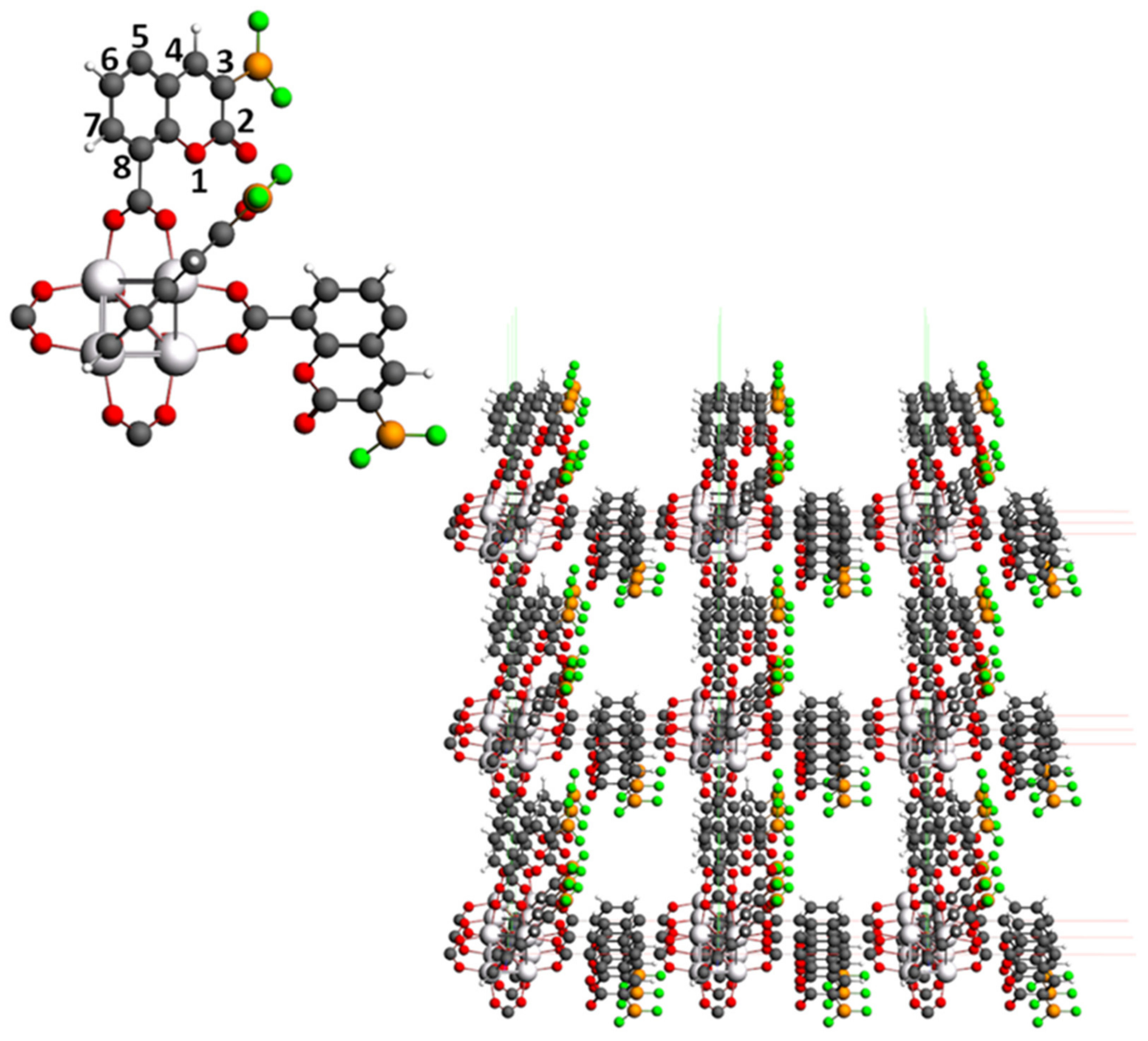
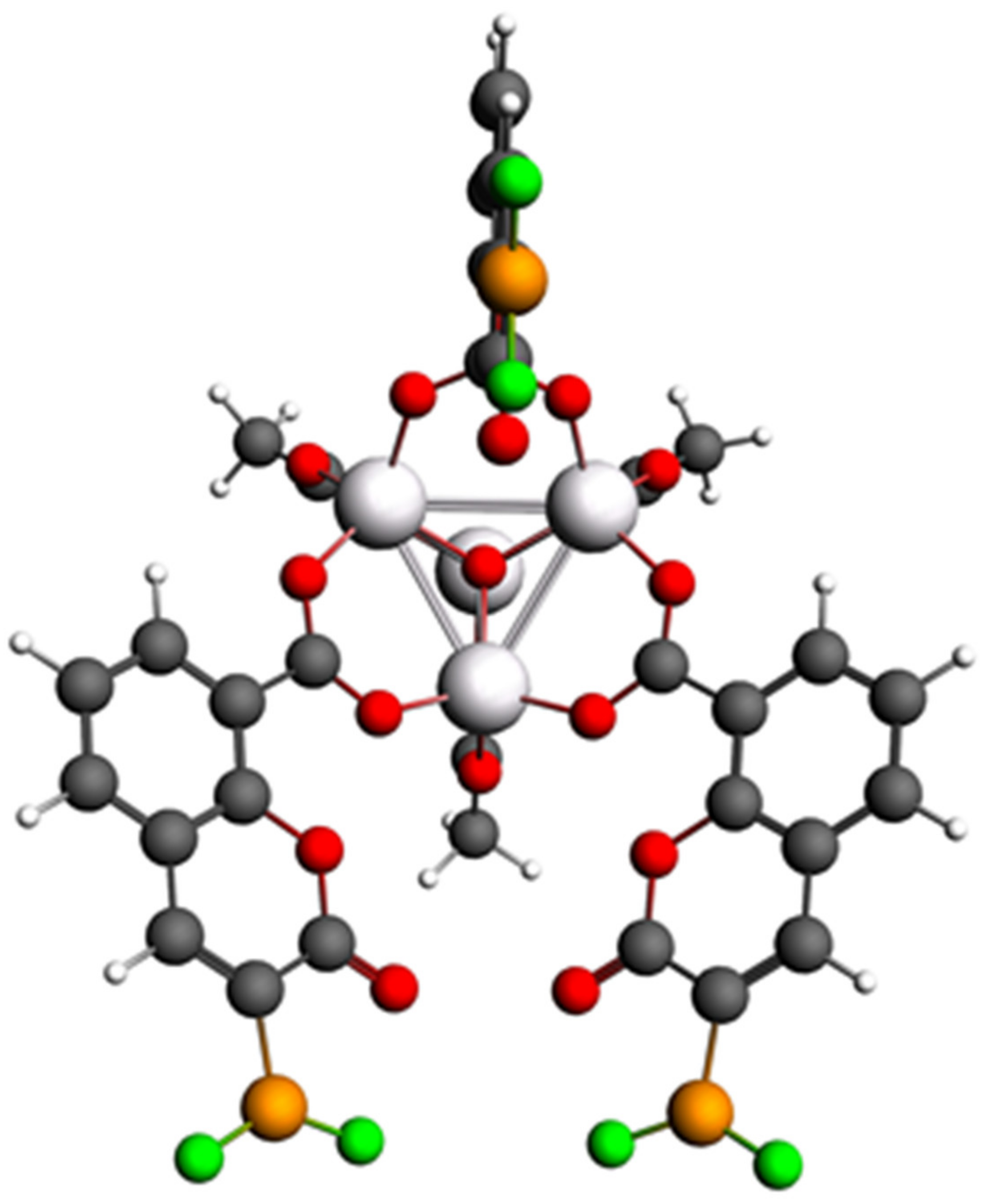
3.1. IRMOF-C-BF2

3.1.1. Primitive Cell of IRMOF-C-BF2

Previous studies [23] limit the modeling of the CO2 photo-reduction properties to the organic linker to model a new MOF, thus, ignoring the effects of the metallic cluster in its core. To evaluate if such approximation is reliable, we compared the optimized geometries of H2 and CO2 adsorption for the most affordable excited state of the primitive cell with the correspondent isolated coumarin derivative linker. Intermolecular distances were mostly inferior for the linker modeled in the absence of the metallic cluster (See Supplementary Materials, Figure S1).
Distances between the two guests and C-BF2 linker imply that their absorption is performed on the linker structure in absence of the metallic cluster; the observed distance between the oxygen atom of CO2 and the B atom is 3.29 Å, H atoms of H2 and the oxygen atom of the carbonyl group are at 2.65 Å. These data lead us to confirm that H2 is susceptible to interact with the basic part of the FLP (O), whereas CO2 prefers the acidic counterpart (B). As mentioned above, the intermolecular distances are larger for the IRMOF-C-BF2 finite model which considers the metallic cluster. An O atom of the CO2 shows a distance of 4.971 Å with the closest hydrogen of the H2 molecule. Moreover, it is evident that H2 is too far from the MOF’s structure, and CO2 is adsorbed close to one of the OCO bridges instead of the nearest linker (the observed distances of each O atom to the C of the closest OCO bridge are 3.867 Å and 4.319 Å). Two hypotheses to explain this particular behavior are: (1) there is a competition between the ligands for the association with the guest molecules; and (2) this behavior is caused by the antagonism of the two electron-rich sites of the MOF, the carbonyl oxygen and the oxygen atoms of the OCO bridges for the absorption of the guest molecules. This situation is more evident for the case of CO2 absorption.
To explain the preference of the guests for the OCO bridges for absorption we have performed an analysis of the Quantum Chemical Topology of the adsorption process using the Quantum Theory of Atoms in Molecules to obtain a quantitative insight from the quantitative binding analysis. We used the absorption geometries reported in the Figure S1. As mentioned previously, some criteria help to evaluate bond characteristics. IRMOF-C-BF2 complex properties are shown in Table 1. All intermolecular interactions that present bond path and BCP with guest molecules adsorbed are shown in molecular graphs in Figures S2–S7. There are several intermolecular interactions with guest molecules, most of them show values for Van der Waals interactions (ρ = ~10−3 au, ∇2ρ > 0 au) [45,51,52]. Delocalization index is a measure of polarity bond, pairs of atoms in closed-shell interactions show delocalization indices close to zero meanwhile in covalent bond tend to 1 [44]. Most of the interactions in these systems agree with weakly bound interactions (DI(X,Y) < 0.05) [53,54,55,56]. Moreover, each interaction represents a positive contribution (destabilization) for guest molecules (ΔE > 0) and some of them are involved in a loss of electronic population (ΔN(X) < 0) [54]. In the next lines, interactions are quantitatively analyzed.
Adsorbed CO2 establish interaction with MOF’s oxygens (69.23%), MOF’s carbons (15.4%), or even MOF’s hydrogens (15.4%), all bond paths and BCP are shown in molecular graphs Figures S2 and S5–S7. CO2 preference for OCO bridges is backed up for BCP. Moreover, Laplacian isosurface shows an electron density concentration at OCO oxygens (Figures S2–S7). That explains how CO2 carbon is attracted to these domains. In this domain, CO2 oxygens are close to other oxygens and interacting with them (Figures S2 and S5). Moreover, CO2 can interact with H2 and H2O, some of such interactions agree with hydrogen bond criteria [57,58,59,60] (i.e., 0.002–0.034 au for electron density and 0.024–0.139 au for Laplacian, 140–180°, ΔE(X) > 0, ΔN < 0, DI(X,Y) < 0.05). Then, CO2 maintains its ability to establish diverse interactions in this domain, especially with MOF’s oxygen. Additionally, guest intermolecular interactions have a stabilizing effect over CO2.
Regarding to the water adsorption, water interact with MOF’s oxygens (75%) and MOF’s hydrogens (25%), all bond paths and BCP are shown in molecular graphs (Figures S4, S5 and S7). Hydrogen bonds were found in the presence of a water molecule (IRMOF-C-BF2--H2O and IRMOF-C-BF2-H2 CO2 H2O) and values of ρ and ∇2ρ (Table 1) are within the expected range (i.e., 0.002–0.034 au for electron density and 0.024–0.139 au for Laplacian). Angles were corroborated (140°–180°) and distance is consistent with a strong hydrogen bond = 2.5–3.0 Å [57,58,59,60]; however, one of them is a non-classical hydrogen bond (IRMOF-C-BF2--H2O).
Regarding adsorbed H2, there are interactions displayed by H2 with MOF’s carbon, MOF’s hydrogens, but not with MOF’s oxygens (Figures S3, S6 and S7). Additionally, dihydrogen bonds that are present in IRMOF-C-BF2--H2 CO2 and IRMOF-C-BF2---H2 CO2 H2O agree with topological criteria (i.e., angle= 90–171°, distance < 2.4–2.6, ρ = 10–2~10−3, ∇2ρ > 0 ua) [55,56].
Guest intermolecular interactions were calculated using the AIMAll program. For each system, intermolecular interactions between H2, CO2, and H2O were detected (see BCP’s in Figures S2–S7). Most of the intermolecular interactions between guest molecules agree with hydrogen bond criteria (Table 2) [57,58,59,60]. Additionally, water and carbon dioxide show an intermolecular BCP (O---C) (Figure S7), whose properties are consistent with Van der Waals interactions [51,52].

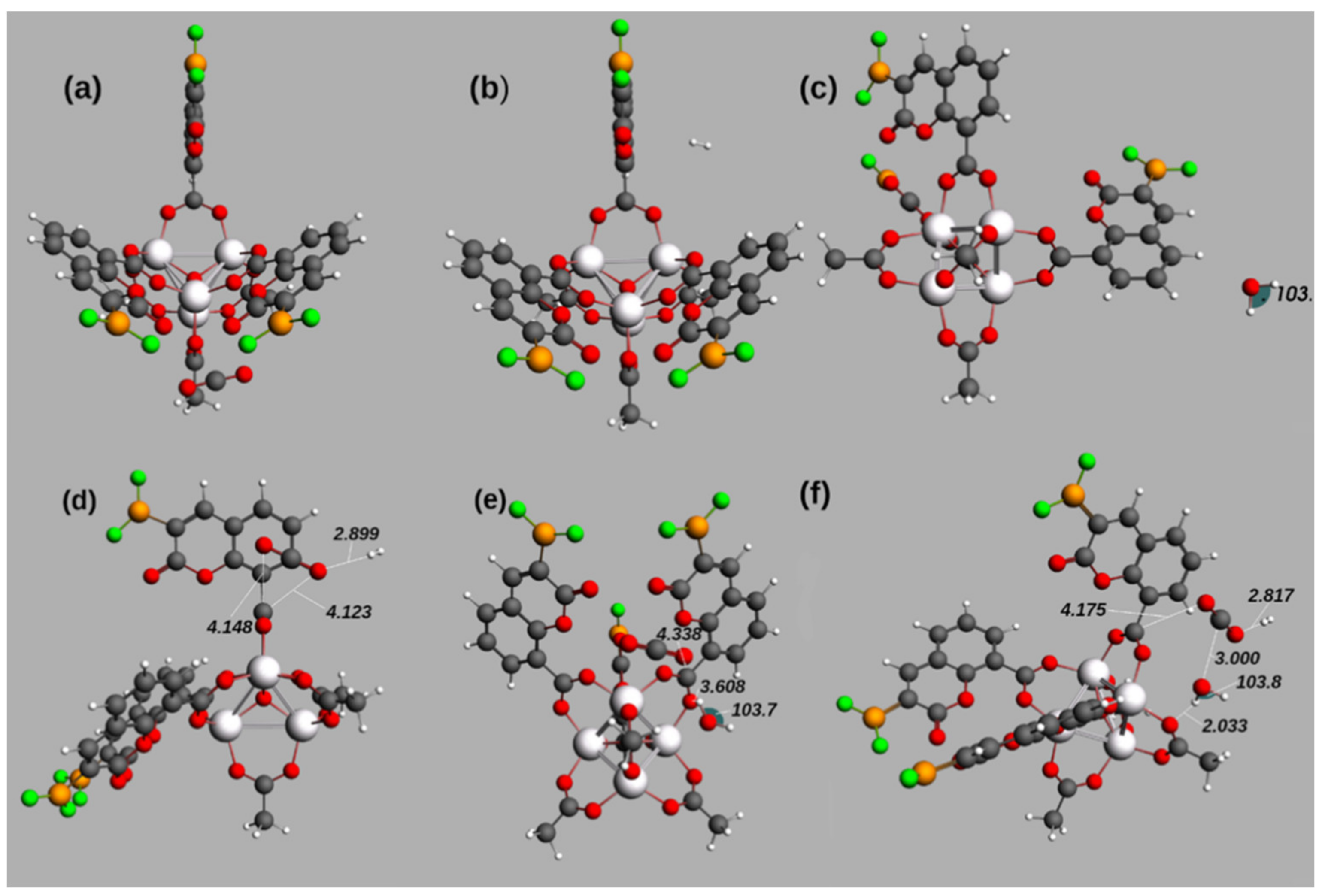
Optical Properties of Primitive Cell of IRMOF-C-BF2 during Adsorption Process

To contrast the optical properties of IRMOF-C-BF2, C-BF2, and IRMOF-1, a calculation of the most affordable excited states was performed, considering CO2 and H2 as guest molecules. The brightest transition for the coumarin derivative is 25 times more probable when it is isolated (C-BF2, Table 3) than when it is bonded at C8 to the metallic cluster (IRMOF-C-BF2, Table 3). The energy of the transition, on the other hand, is 1.48 times greater for C-BF2 (4.0 eV) than for IRMOF-C-BF2 (2.7 eV). The optical properties of coumarin are appreciably decreased when it is attached to a MOF, considering the oscillator strength (f) of vertical photo-excitations. Nevertheless, there is a probable improvement of the optical properties displayed by IRMOF-C-BF2 compared with IRMOF. IRMOF-C-BF2 shows a smaller energy of excitation, which was localized in the visible part of the electromagnetic spectra (Figure S8a)), such behavior is desirable for photocatalytic devices. Comparing the observed transitions in IRMOF-1 and IRMOF-C-BF2, it is clear that the change in the ligand’s nature has positive effects both in the energy of the brightest transition and its probability (given by a higher f) (Figure S8a), Table 3). IRMOF-C-BF2 shows a transition 14.7 times brighter than for IRMOF-1, whose respective energies are 2.7 eV and 4.2 eV. This implies a noticeable improvement of the optical properties to activate photocatalysis when a coumarin-like replaces the benzenoid linker in IRMOF-1.
Table 4 and Figure 3 show the optimized geometries of the brightest excited states of the adsorption of H2, CO2, and H2O in IRMOF-C-BF2. Structure of Figure 3a) shows the adsorption of CO2 close to an OCO bridge (4.028 Å between the C of the bridge and the nearest O of CO2) and to one of the coumarin-derivative-linkers (with a distance of 5.007 Å between the B and an O of the guest). Regarding the adsorption of H2 (Figure 3b) and H2O (Figure 3c), the distances between the guests and IRMOF-C-BF2 are larger than 6.00 Å. On the other hand, Figure 3d–f displays geometry optimizations that imply more than one guest molecule. The closest proximity of adsorbed molecules to the MOF structure and among them are shown in Figure 3d) for adsorption of H2 followed by CO2 and Figure 3e) for adsorption of CO2 and then H2O. In the case of H2 and CO2 adsorption (Figure 3d), the oxygen atoms of CO2 are located at 4.148 Å and 4.123 Å of the carbon of an OCO bridge of MOF; H2 molecule is located at 2.899 Å of adsorbed CO2. In the case of CO2 and H2O as guest molecules (Figure 3e), CO2 is localized near a carbon atom of a OCO bridge, at 4.388 Å; the water molecule is localized at 3.608 Å of one oxygen of the same OCO bridge. The bond angles and interatomic distances of adsorbed molecules are not affected in any of the structures. Regarding the adsorption of H2 followed by CO2 and then H2O (Figure 3f), the places where H2, CO2, and H2O adsorb are similar to those observed for the two guest molecules. Thus, the results involving more than one guest molecule suggest a reaction between the guest molecules, mediated by the MOF structure.
Regarding the vertical excitations, the ones with higher f value are singlet-singlet transitions. The brightest ones are shown in Table 5. As showed, f values for IRMOF-C-BF2 with and without guest molecules are, despite their magnitudes, 10 times greater than the respective ones for IRMOF-1. Furthermore, the energy required for electron excitation is 150% smaller for IRMOF-C-BF2 than for IRMOF-1 (the optimized geometries in the absence of guest molecules are taken as reference).
The information related to the photocatalytic capability of the IRMOF-C-BF2 can be obtained from the characterization of the Potential Energy Surface (PES), such study is in progress. With this regard, a characterization of some candidate transition states and maximums found along the optimization process of the excited states, are presented in the Supplementary Materials (Figures S9 and S10). A relevant observation is that at such maximums, the absorbed guest molecules display large distortions of their geometry.

Change in Order of the Guests’ Adsorption for Geometry Optimization in IRMOF-C-BF2

We performed the adsorption of the guest molecules adding CO2 and then H2 to IRMOF-C-BF2, to compare the optimized absorption geometries at the brilliant excited states. Figure S11 shows the resultant geometry, for which a slight difference can be perceived when compared to Figure S1, in which the guest molecules are added in the opposite order. CO2 is near three different atoms in the MOF structure (Figure S11): its carbon atom is placed in the middle of two oxygen atoms of different kind, the first one located at 3.721 Å is the carbonyl oxygen of a linker; the second one is located at 3.157 Å and forms part of the OCO bridge located just next to the C-BF2 linker. Regarding the oxygen atom of CO2, it is placed farthest to the central cluster and it is also near the OCO bridge, at 4.826 Å. In contrast with the original adsorption order, H2 then CO2, in this experiment adsorbed H2 is located between the adsorbed CO2 molecule and the central cluster of the primitive cell. The distance among both guests is 3.161 Å. It is remarkable that when CO2 is added first, both guests are absorbed closer to the C-BF2 linker. Finally, the energies of both geometries are similar, –608.917 eV when H2 is added first and –608.753 eV when CO2 is added first.
Regarding the binding displayed for these systems, AIM properties of BCP were obtained and intermolecular interactions were analyzed (Table 1 and Table 6). BCP and bond paths are shown in the molecular graph (Figures S6 and S12). Change in order addition results in different behavior in guest localization and intermolecular interactions. In the case of IRMOF-C-BF2---H2 CO2, molecular hydrogen is adsorbed first; it prefers to interact with the aromatic framework of coumarin (it is consistent with its behavior in IRMOF-C-BF2---H2, see Figure S3, where it interacts with aromatic ring). Then CO2 is added, it is attracted to OCO framework (Figure S6), CO2 is near H2 and they form an interaction that agrees with hydrogen bond criteria (Table 2). In the case of IRMOF-C-BF2---CO2 H2, carbon dioxide is adsorbed first; it is attracted to the OCO region and carbonyl of coumarin (this agrees with IRMOF-C-BF2---CO2, see Figure S2, where CO2 interacts with carbonyl groups and OCO region). Then H2 is added, and it interacts with the aromatic ring of coumarin and forms an O—H interaction that agrees with hydrogen bond criteria (Table 7) with CO2 (Figure S12). The number of intermolecular interactions of guest and IRMOF-C-BF2 is larger when CO2 is added first (Table 6) because the dioxide interacts with OCO and carbonyl frameworks. This behavior is present in IRMOF-C-BF2---CO2 H2O and IRMOF-C’-BF2---H2 CO2. In IRMOF-C-BF2---CO2 H2, most of intermolecular interactions are consistent with Van der Waals interactions (ρ = ~10−3 au, ∇2ρ> 0 au and DI(X,Y) < 0.05) (Table 7) [51,52].

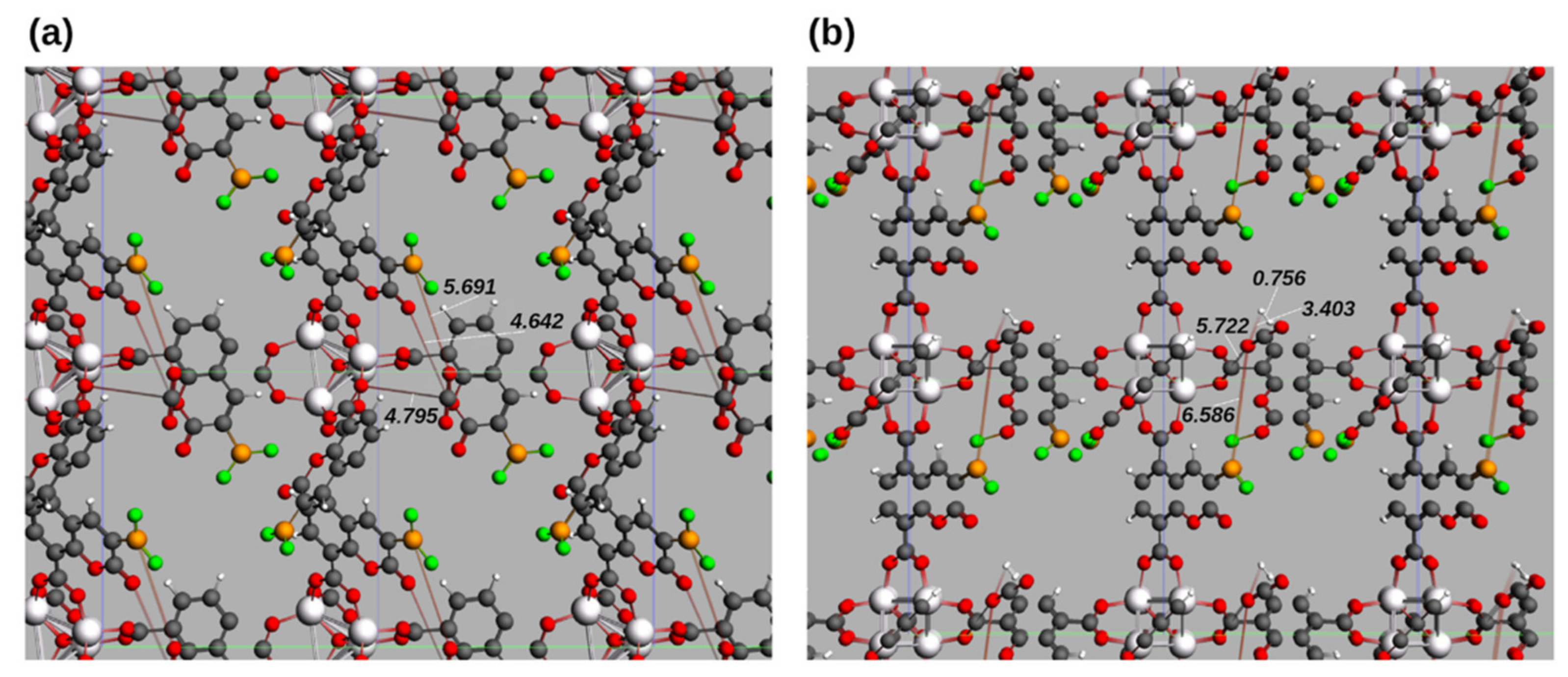
3.1.2. Unit Cell of IRMOF-C-BF2

Unit cell geometries with H2 and CO2 as guest molecules were optimized and evaluated using BAND-ADF to confirm the changes in the properties of the primitive cell. We have special interest on the geometries adopted by the guests and the structure of the valence and conduction bands of the semiconductor cluster in the center of each node.
As can be seen in Figure 4, when the geometry optimization is performed considering the bulk structure of the unit cell, the guest molecules are located slightly more distant to the Lewis acid and base moieties of the FLP. When CO2 is the only guest molecule (a), the distances between the CO2 molecules and one of the linkers are: 5.692 Å from one oxygen atom of CO2 and the closest boron of the linker (BO distance), and 4.642 Å for the carbon-oxygen distance (CO) between the CO2 carbon and the carbonyl oxygen. The OCO bridge and the guest are located at 4.795 Å (CO distance between the carbon of CO2 and the closest oxygen of the indicated bridge). In addition, there is no change in bond angles or distances in CO2. When both H2 and CO2 are present (b), the distances between CO2 and the MOF structure are slightly increased: the CO distance between the carbon atom of CO2 and the closest oxygen atom in the OCO bridges is 5.722 Å, whereas the OB distance to the closest BF2 group is 6.568 Å. The guest molecules are located at 3.403 Å from each other, a value similar to the one obtained for calculations on the primitive cell. As in the case of the single guest adsorption, there are no significant changes in the bond distances and bond angles in the guest’s structures.
According to previous theoretical works, the band gap of IRMOF-1 is decreased when halogens are added to the linkers [61] or when the linkers are longer containing more conjugated carbon atoms [62]. Consequently, the band gap of IRMOF-C-BF2 is expected to decrease in a similar way, resulting in an improvement of the conduction properties of the MOF. The band properties of the isolated unit cell and the unit cell in the presence of guests are reported in Table 8. For the isolated unit cells, the band gap is considerably decreased from 3.4 eV to 0.403 eV (88.2 %); this is consistent with a previous report for linkers with more conjugated carbon atoms [62]. Such result implies a semiconductor behavior, with an increased facility for electronic conduction. The DOS of IRMOF-C-BF2 shows the contribution of the different atoms in both the valence and conduction bands (Figure S11). The major contribution to the valence band comes from the most electronegative atoms located in both the central MOF cluster and linkers (O atoms), whereas Zn and C atoms in the MOF cluster have both major contributions to energies surrounding the Fermi level (Figure S11b)). This can be explained as a result of the influence of the electronegativity and the atomic effective charge on the shielding of the valence orbitals, the latter holds for the case of the Zn atom. The C atoms in the linker c) show a similar pattern to the C atoms in the cluster, with an appreciable contribution to both the valence and conduction bands, majorly due to their electronegativity and the amount of them in the MOF’s structure. The FLP proposed behaves according to the assumption that the B atoms would act as Lewis acids (with greater contribution to the conduction band) and the O atoms as Lewis bases (with greater contribution to the valence band) d). Considering the proximity of the energy levels generated by O atoms, it seems reasonable that the C atoms of CO2 associate to both the carbonyl and OCO bridge’s oxygen atoms.
Comparing the energy parameters for the conduction and valence bands (Table 8), addition of a CO2 guest decreases the band gap (6.2% of decrease, from 0.403 eV to 0.378 eV) keeping the limits of both bands almost intact (- 4.789 to −4.408) eV. The major changes takes place when both guest molecules, H2 and CO2, are introduced to the MOF: an augment in the band gap (77.2% of augment, from 0.403 eV to 0.714 eV) resulting from a decrease in the bottom limit of the valence band (to −5.089 eV) and growth in the top of the conduction band (to −4.354 eV).
To analyze intermolecular interactions, QTAIM properties were calculated. However, to use less computing resources, only rigid fragments were evaluated. Molecular graphs show bond paths and BCP of intermolecular interactions in each system (Figures S13 and S14). Comparing bulks and isolated frameworks (IRMOF-C-BF2 unit cell CO2 with IRMOF-C-BF2---CO2 and IRMOF-C-BF2 unit cell CO2 H2 with IRMOF-C-BF2---H2 CO2), it was found that some interactions changed, then some BCP properties. One clear example of this is observed in O---O interaction with CO2 and carbonyl oxygen (see Table 1 and Table 9) where a decrease in ρ, ∇2ρ and DI(X,Y) is observed in bulk structure when is compared with the isolated framework, which means less bonding strength. This behavior is consistent with an increase in distance [44]. Additionally, in the presence of H2 and CO2, there are more intermolecular interactions in bulk system than in isolated framework (Table 1 and Table 9). These new intermolecular interactions come from H2 and bulk atoms, with OCO region, coumarin carbon (H---π), and carbonyl region. Moreover, one of its two H---O interactions (Table 9 and Figure S14) agrees with hydrogen bond criteria [57,58,59,60]. On the other hand, CO2 has two Van der Waals interactions [51,52].
Guest intermolecular interactions were obtained using the AIMAll program. Intermolecular interactions were detected between H2 and CO2 (Figure S14). Such interaction is formed between H---O; however, it does not agree with hydrogen bond criteria, mainly because of its angle (89.15°) (Table 10, it corresponds to a Van der Waals-like interaction [51,52]. This assumption is supported by topological properties. For example, if we compare the interactions with those for the isolated unit cell, Table 10 vs. Table 2, it is evident that binding properties of H---O such as electron density, Laplacian, and delocalization index are larger in magnitude.

3.2. IRMOF-C’-BF2

3.2.1. Primitive Cells of IRMOF-C-(2)-BF2 and IRMOF-C’-BF2

Based on the previous observations that both H2 and CO2 adsorb preferentially close to the central cluster of IRMOF-C-BF2, a new linker was designed. Figure S1 shows that CO2 adsorbs near one of the OCO bridges of IRMOF-C-BF2. With this regard, a BF2 group added on carbon C7 of the coumarin moieties will form a new FLP (formed by one oxygen atom of one OCO bridge and the boron on the coumarin moiety). Such FLP could be more suitable for guest adsorption over the pair formed by the carbonylic oxygen and the BF2 group C3 carbon of the linker.
To prove this hypothesis, a MOF structure with BF2 groups on carbons C3 and C7 is modeled (IRMOF-C-(2)-BF2). Geometry optimizations for H2 and CO2 adsorbed in IRMOF-C-(2)-BF2 were carried out. Figure 5b) shows the results of the competition for guest molecule’s absorption in the MOF structure. The BF2 group placed closer to the OCO bridges of the central cluster is preferred over the one in the α-position to the carbonyl groups. The OB distance between CO2 and the closest B (BF2 group) is 4.462 Å. The carbon of adsorbed CO2 is located at 3.793 Å of one of the oxygen atoms of the OCO bridge connected to the same linker as BF2, which the molecule is interacting with. This indicates that CO2 is being absorbed by the FLP built to include the OCO bridge. In addition, the guests are at 2.807 Å from each other (measuring the distance between the closest atoms of each guest, CO2 oxygen and H2 hydrogen); notice that the oxygen atom of CO2 that is located closest to H2 is not involved with the new FLP mentioned above. The hydrogen in H2 that is farthest of CO2 is observed almost in the middle of both oxygen atoms of the ester of another linker (3.363 Å from the O in the ring and 4.203 Å of the carbonylic oxygen).
An important question to be solved is: is the adsorption near OCO bridges improved by the BF2 groups not directly involved in it? To give an answer to this question, the MOF structure IRMOF-C’-BF2 was built (Figure 5c), maintaining the BF2 groups on C7 of the coumarin moieties but eliminating the other ones. Geometry optimizations for the IRMOF-C’-BF2 were performed, maintaining the addition order of the guest molecules (H2 followed by CO2). Figure 5c shows the guests as close to each other as when adsorbed on IRMOF-C-BF2. The distances among them are 3.193 Å for the HO interaction (measured between H2 and the closest oxygen of CO2) and 3.364 Å for the HC interaction (measured between H2 and the carbon atom of CO2). These values are smaller than the ones observed for IRMOF-C-BF2 (a), 4.971 Å for the HO distance) and larger than those observed for IRMOF-C-(2)-BF2 (b), 2.807 Å for the HO distance). Nevertheless, H2 is adsorbed in such place in IRMOF-C’-BF2 not just because of its proximity to CO2, but in response to the presence of the carbonyl oxygen atom in the closest linker (displaying a HO distance of 2.709 Å). Moreover, the proximity of H2 to atoms other than those in CO2 is not as remarkable as for IRMOF-C-(2)-BF2. In addition, there is a distance of 4.241 Å between an oxygen atom of CO2 and the carbon atom of the closest OCO bridge. It is noticeable that when a BF2 group is placed near the OCO bridges (b,c)) the guest molecules are adsorbed in the middle of two linkers.
Until this point, the proximity of the guests-MOF is comparable for both IRMOF-C-(2)-BF2 and IRMOF-C’-BF2. In addition, their absorption is apparently better (at closer proximity with the MOF structure) than in IRMOF-C-BF2. To discern the most suitable MOF for H2 and CO2 absorption, the excited states that could lead to electronic vertical excitations were obtained (Table 11). For the brightest transition, the probability estimated for the three MOF has the same magnitude order (10−3), although the probability calculated for IRMOF-C-BF2 is slightly greater than the one for IRMOF-C-(2)-BF2 and IRMOF-C’-BF2 (2.5 × 10⁻³ and 6.3 × 10⁻³, respectively). The energies of the optimized transitions show an interesting behavior (Table 11): for IRMOF-C-(2)-BF2, the energy of the brightest transition is decreased (to 1.96 eV, 27.4% of decrement). In contrast, the energy of such transition in IRMOF-C’-BF2 is augmented (to 3.0 eV, 11.1% of increment). This implies that the gap between the ground and the excited state is bigger when there is just one B atom per linker than when there is more than one. This is caused by an augment of the ground state’s energy in the case of two BF2 groups on the coumarin moiety. Furthermore, the electrons on the HOMO are more stabilized if the boron atoms are located closer to the central cluster of the MOF (Table 8). The energies of the bottom of the valence band are – 5.089 eV for IRMOF-C-BF2 (B on C3) and – 6.476 eV for IRMOF-C’-BF2 (B on C7). This observation could be explained by the increased contribution of fluorine atoms to the valence band when they are closer to the metallic cluster (Figures S11 and S15). If the valence and conduction bands are more separated in IRMOF-C’-BF2, it is evident that the energy of its brightest transition will be larger.
Intermolecular interactions of both systems (IRMOF-C’-BF2 and IRMOF-C-(2)-BF2) were analyzed; AIM properties of BCP were obtained (Table 12). BCP and bond paths are showed in molecular graphs (Figures S16 and S17). Energy contribution, E(X), points out to destabilization contribution from guest molecules, especially in CO2 molecule. The delocalization index agrees with noncovalent interactions (<0.05) [53,54], Laplacian, and electron density agree with Van der Waals interactions [51,52].
Absorbed CO2 shows interactions with MOF’s oxygens, MOF’s carbon, and even with H2 (Figures S16 and S17). BCP pointed out the interaction between CO2 and H2, in agreement with hydrogen bond criteria in IRMOF-C’-BF2 [57,58,59,60]. CO2 is attracted to the carbonyl domain and can interact with coumarin oxygens in IRMOF-C’-BF2, but this attraction is weaker in IRMOF-C-(2)-BF2. Additionally, parameters are similar to those observed in CO2 in a previous system (Table 1, IRMOF-C-BF2---CO2 H2O), but the number of interactions is fewer, because in IRMOF-C-BF2---CO2 H2O carbon dioxide access more easily to OCO and carbonyl frameworks than CO2 in IRMOF-C’-BF2 and IRMOF-C-(2)-BF2. Laplacian isosurface shows electron density concentration in OCO and coumarin oxygens, where guest molecules are attracted.
As CO2, molecular hydrogen is attracted to the OCO framework too, it shows interactions with MOF’s carbon and one hydrogen bond interaction with coumarin oxygen in IRMOF-C’-BF2. Such hydrogen bond fully agrees with the common hydrogen bond criteria (Table 12) [57,58,59,60]. Furthermore, there are H---π interactions between H2 and coumarin in both systems.
Guest intermolecular interactions were analyzed using AIM descriptors. Intermolecular interactions were detected between H2 and CO2, see BCP in Figures S16 and S17. There are O---H interactions; however, one of these interactions in IRMOF-C’-BF2 does not agree with hydrogen bond criteria [57,58,59,60] because of its angle (112.87°) (Table 13).
To compare the differences in the optical properties of the purposed MOF (IRMOF-C’-BF2) and its isolated linker (C’-BF2), a calculation of the excited states in UV and Visible regions was performed, using optimized geometries (Figure S8b). Once again, it is clear the isolated linker structure (C’-BF2) shows brighter transitions (Table 3). Comparing the linker’s transitions (C’-BF2 and C-BF2), their energies are 5.4 eV for C’-BF2 with an f value of 0.305, and 4.0 eV for C-BF2 with an f value of 0.210. Although the energy is increased when changing the BF2 moiety from C3 to C7, it is weighted by a transition 1.4 times brighter. The different MOF structures are similar in energy (2.7 eV for IRMOF-C-BF2 and 3.0 eV for IRMOF-C’-BF2) and similar in f values (8.4 × 10⁻³ for IRMOF-C-BF2 and 6.3 × 10⁻³ for IRMOF-C’-BF2).

3.2.2. Unit Cells of IRMOF-C’-BF2

Regarding the bulk properties, the band gap of the unit cell of IRMOF-C’-BF2 is decreased with respect to IRMOF-1 [30,32] (Table 8), such behavior is similar to the displayed by IRMOF-C-BF2. The calculated value of 2.413 eV implies a decrease of 29.0% with respect to IRMOF-1, which is much smaller than the one obtained for IRMOF-C-BF2 (IRMOF-C-BF2 displays 88.1% of decrement and a band gap of 0.403 eV). The energy of the bottom of the valence band and the top of the conduction band are 6.476 and 4.082 eV, respectively. Although the structure of the linkers in both purposed MOFs is similar, the placement of the boron atom closer to the OCO bridges and far from the carbonyl moiety in the coumarin ring causes an increase in the band gap.
The information of the contributions of the different atoms that compose the MOF in its valence and conduction bands are placed in the DOS (Figure S15). The major contribution to the valence band comes from the most electronegative atoms both in the central cluster and linkers (oxygen atoms and fluorine atoms), whereas zinc atoms in the cluster have important contributions to the states surrounding the Fermi level (Figure S15b)); this can be understood as the influence of the electronegativity for non-metal atoms, and in the case of the zinc atom by the effect of the atomic effective charge on the shielding of the valence orbitals. The carbon atoms in the central cluster exhibit a contribution oriented to the conduction band (b), nevertheless, there is an appreciable contribution of such carbon atoms to the valence band. The carbon atoms in the linker (c) follow a different pattern, they have an appreciable contribution to both the valence and conduction bands, majorly due to their electronegativity and their location on the electron-rich coumarin rings. The FLP behaves with the boron atoms as Lewis acids; they have a greater contribution to the conduction band. In addition, the oxygen atoms of the OCO bridges play as Lewis bases; they have a greater contribution to the valence band (d). Considering the proximity of the energy levels generated by oxygen atoms, it seems reasonable that the C atoms of CO2 prefer the association with the OCO bridge’s oxygen atoms. In addition, oxygen atoms of CO2 prefer to interact with carbon atoms from the OCO bridges and with the boron atoms of BF2, both with major contributions to the conduction band.
DOS of IRMOF-C-BF2 (Figure S11) and IRMOF-C’-BF2 (Figure S15), have more populated valence bands; this difference in population is bigger for IRMOF-C’-BF2. Fluorine atoms of the linkers and carbon atoms of the OCO bridges show an appreciable difference when present in the two MOFs. Fluorine atoms contribute to both valence and conduction bands over a wide range of energies in IRMOF-C-BF2 but show a localized role in a few states of remarkable population density in IRMOF-C’-BF2. This might be related to a redistribution of the fluorine electron density when these atoms are located closer to the central cluster. Carbon atoms of the OCO bridges display an active role on the conduction band of IRMOF-C’-BF2, this is not observed in IRMOF-C-BF2. It is possible that the proximity of the fluorine atoms (electron-rich entities) of the linkers increase the energy of frontier orbitals due to electronic repulsion.

3.3. IRMOF-C-CH2BF2

Primitive Cells of IRMOF-C-CH2BF2

IRMOF-C-CH2BF2 was purposed as a MOF whose organic linker could be more suitable to be synthesized than the displayed by IRMOF-C-BF2. The optimized geometry when H2 and CO2 are added is shown in Figure 6. The proximity of the guest molecules to the MOF is comparable to that obtained for a similar treatment with the MOF purposed herein (IRMOF-C-BF2, Figure S1; IRMOF-C’-BF2, Figure 5c)). The proximity of both guests is of 3.317 Å (OH closest distance); each guest adsorption is influenced by two groups on the MOF. In addition, the hydrogen atom of H2, farthest of the CO2 molecule, is adsorbed close to two OCO bridges; the OH distances among them are 4.381 Å and 4.791 Å. Moreover, CO2 is located near a FLP in one of the linkers, its oxygen atom that is not in proximity of H2 is at 4.493 Å of boron. In addition, the C of CO2 is located at 3.332 Å of the carbonyl oxygen of the coumarin moiety.
BCP’s in IRMOF-C-CH2BF2 were calculated to analyze intermolecular interactions with guest molecules (CO2 and H2), AIM properties of BCP were obtained (Table 14) and in the following lines, interactions are analyzed.
As was observed in a similar system (i.e., IRMOF-C’-BF2---H2 CO2), in IRMOF-C-CH2BF2 CO2 and H2 are attracted to OCO domain (Figure S18). Interaction properties (Table 14) agree with no covalent interactions [51,52]. Molecular graph (Figure S18) shows the BCP’s and bond paths for some intermolecular interactions. CO2 interacts with coumarin oxygen and coumarin carbon, but with H2. On the other hand, H2 has direct contact with oxygens in OCO and coumarin oxygen. This last interaction agrees with hydrogen bond criteria [57,58,59,60].
Additionally, an intermolecular interaction between H2 and CO2 was found, and its topological properties are shown in Table 15. There is an O---H interaction, it does not agree with hydrogen bond criteria because its angle (90.48°), but its properties are consistent with noncovalent interactions [51,52].
The excited states of IRMOF-C-CH2BF2 in the presence of H2 and CO2 as guest molecules were calculated (Table 3, Figure S4c)). In comparison to the previous linkers, the brighter excited state of C-CH2BF2 has a greater f value (0.331); its energy of 4.0 eV is similar to that of C-BF2, which implies that the inclusion of an electron deficient substituent, regardless of its nature (BF2 or CH2BF2), leads to a brighter state at 4.0 eV. It is remarkable, however, that the addition of a CH2 group increases the probability of the mentioned transition. Whit this regard, similar characteristics of the brighter states of C-CH2BF2 and C’-BF2 are observed, although it is clear that C’-BF2 requires less energy for the mentioned transition. The IRMOF-C-CH2BF2 has an important improvement in energy, comparing the energy needed for the transition, it is just 0.59 times the value reported for IRMOF-1. Such situation is not possible with IRMOF-C-BF2 or IRMOF-C’-BF2 (Table 3). In addition, the probability to reach the brighter transition is 8.8 times greater than the reported value for IRMOF-1, belonging to the same magnitude to the MOF purposed in this paper.

3.4. Further Topological Analysis of All Possible Intermolecular Hydrogen Bond

In the framework of QTAIM a decrement of the kinetic energy density (G) at BCP is related to a depletion of the electron density, because this situation implies less repulsion among electrons. Moreover, this behavior is observed at the hydrogen bond BCP when the hydrogen bond distance is increased, d(H---O) [62,63,64]. In addition, the positive curvature of ρ at the BCP, λ3CP, shows a good correlation with d(H---O), at variance with ρ and ∇2ρ displaying large data dispersion. With this regard, Espinosa and co-workers proposed a formula to calculate G at the bond critical point GCP using λ3CP as a variable in a linear fitting, GCP = 15.3(1) λ3cp. [63] Then, the strength of a hydrogen bond is unambiguously characterized by GCP, the stronger the hydrogen bond the stronger repulsive among electron at BCP, increasing λ3CP and therefore GCP. To clarify hydrogen bond interactions between MOFs and molecular guest, additional kinetic energy (GCP) and positive curvature (λ3CP ) analyses were performed (Table S1), all possible intermolecular hydrogen bonds were considered. Graphical plot of λ3CP vs. d(H---O) exhibits a similar behavior reported by Espinosa [63,64], (see Figure S19). Furthermore, G vs. d(H---O), Figure 7, displays the expected behavior reported by Espinosa. In base of GCP values the complete set of hydrogen bonds observed for guest molecules adsorbed in our modeled MOFs are consistent with a closed-shell interaction. Moreover, three strong hydrogen bonds are displayed related with water adsorption, which λ3 values (6.6, 4.9, and 12.2) highlight over the rest.

4. Conclusions

We modeled four MOFs (IRMOF-C-BF2, IRMOF-C-(2)-BF2, IRMOF-C’-BF2 and IRMOF-C-CH2BF2) based on IRMOF-1 and a linker based on Frustrated Lewis Pairs and coumarin moieties to confer photocatalytic properties to the MOFs. The four different linkers used: (a) a BF2 attached to a coumarin moiety at position 3, (b) two BF2 attached in the coumarin moiety at positions 3 and 7 C-(2)-BF2, (c) one BF2 attached to the coumarin moiety at position 7, and (d) one CH2BF2 attached to the coumarin moiety at 3 position. We observe that the adsorption of H2, CO2, and H2O is possible and that it is probable that the systems will display CO2 photocatalytic properties.
In addition, we find that the hydrogen molecule is susceptible to interact with the basic part of the FLP (O), whereas carbon dioxide prefers the acidic counterpart (B). Moreover, for the MOFs primitive cells modeled, adsorbed H2 is far from the MOF’s structure and CO2 is adsorbed near one of the OCO bridges instead of the nearest linker. Moreover, BF2 attached to the coumarin reduces the vertical transition probabilities of such chromophore. Isolated Coumarin-BF2 moieties display larger optical properties than when being linkers in a MOF. Nevertheless, C-BF2-like linkers improve optical properties of IRMOF-1 by itself, thus an opportunity in this direction is evinced. The characterization of the binding properties by means of AIM shows that the adsorption of the guest molecules is the consequence of the formation of relevant binding interactions, as hydrogen bonds, Van der Waals forces, and electron localization and delocalization interactions.
Structure and adsorption properties of synthesized MOFs could be different to the expected ones, for instance, displaying lower adsorption efficiency to the calculated [65]. For this reason, an important question to be solved is: have this Coumarin-BF2 linkers produce MOF defects that negatively affect the stability, adsorption, and catalytic properties, beyond the predictive computational capability? Whit this regard, we have an encouraging clue: similar linkers display common MOFs structures as was reported by Hendon et al. [66]. In addition, the same study presents modeling results in agreement with experimental structures of synthesized MOFs. Moreover, the characterization of changes of electron density during guest (CO2, H2, H2O) adsorption is relevant to the understanding of the interactions responsible for the stability of guest-MOF complexes. Whit this regard, G(CP) and λ3 results are used to classify the strength of the displayed hydrogen bonds of adsorbed molecules, finding 3 relevant hydrogen bond interactions related with water adsorption. Currently, we focused on the analysis of behavior of ρ(r) positive curvature (λ3) and G(GP) at the bond critical point versus the topological distance, [63,64,66] along the guest adsorption reaction path.
The relevance of our present work relies on the plausibility of the improvement of photocatalytic properties of IRMOF using Coumarin-BF2 linkers. Nevertheless, future computational and experimental work is needed to study the changes of the interactions along the adsorption process and to test the photocatalytic efficiency of such new MOFs.

Supplementary Materials

The following are available online. Figure S1. Optimized geometries for the calculation of the brightest excited states of the primitive cell (IRMOF-C-BF2) and the linker (C-BF2) in the presence of H2 and CO2. Figure S2. (a) Electron density topologies for IRMOF-C-BF2···CO2. Figure S3. (a) Electron density topologies for IRMOF-C-BF2···H2. Figure S4. (a) Electron density topologies for IRMOF-C-BF2···H2O. Figure S5. (a) Electron density topologies for IRMOF-C-BF2---CO2 H2O. Figure S6. (a) Electron density topologies for IRMOF-C-BF2---H2 CO2. Figure S7. (a) Electron density topologies for IRMOF-C-BF2---H2 CO2 H2O. Figure S8. Calculated UV and Visible spectra of MOF and its parent linkers in the presence of H2 and CO2 as guest molecules. Figure S9. Energetic maximums obtained during excited states optimizations for IRMOF-C-BF2-H2-CO2. Figure S10. Energetic maximums obtained during excited states optimizations for IRMOF-C-BF2-CO2-H2O. Figure S11. Density of States of IRMOF-C-BF2, as a function of energy (eV). Figure S12. (a) Electron density topologies for IRMOF-C-BF2---CO2 H2. Figure S13. (a) Electron density topologies for IRMOF-C-BF2 unit cell CO2. Figure S14. (a) Electron density topologies for IRMOF-C-BF2 unit cell CO2 and H2. Figure S15. Density of States of IRMOF-C’-BF2, as a function of energy (eV). Figure S16. (a) Electron density topologies for IRMOF-C-(2)-BF2 unit cell CO2 and H2. Figure S17. (a) Electron density topologies for IRMOF-C’-BF2---H2 CO2. Figure S18. (a) Electron density topologies for IRMOF-C-CH2BF2---CO2 H2. Figure S19. Behavior of λ3CP versus d(H---O). Table S1. Analysis of Quantum Theory Atoms in Molecules for hydrogen bonds. Table S2. xyz-coordinates of the geometries for the optimized molecules.

Author Contributions

P.C.: Molecular Modelling, interpretation of data, Writing—Original Draft Preparation; J.G.H.-L.: Characterization of Chemical interactions by means of Quantum the Theory of Atoms in Molecules, interpretation of data, Writing—Original Draft Preparation; A.B.-J.: supercomputing resources, software optimization, hardware-software management, Project Administration, Funding Acquisition; M.A.G.-R.: Research responsible, original idea, scientific discussion, Review & Editing, Project Administration, Funding Acquisition. All authors have read and agreed to the published version of the manuscript.

Funding

CONACYT postdoctoral fellow (270750) and DAIP-UG (13172021).

Institutional Review Board Statement

Not applicable.

Informed Consent Statement

Not applicable.

Data Availability Statement

Not available.

Acknowledgments

The authors would like to thank the National Laboratory UG-UAA-CONACYT 123732, for supercomputing resources. M.A.G.-R. thanks to CIIC-DAIP-UG (131/2021) for financial support and P. Lozano-Sotomayor for an extensive revision of manuscript language. J.H.-L. thanks CONACYT for postdoctoral fellowship (270750).

Conflicts of Interest

The authors declare no conflict of interest.

Sample Availability

Samples of the compounds are available from the authors.

References

  1. Wang, Q.; Astruc, D. State of the Art and Prospects in Metal–Organic Framework (MOF)-Based and MOF-Derived Nanocatalysis. Chem. Rev. 2020, 120, 1438–1511. [Google Scholar] [CrossRef]
  2. Zhao, X.; Feng, J.; Liu, J.; Lu, J.; Shi, W.; Yang, G.; Wang, G.; Feng, P.; Cheng, P. Metal-Organic Framework-Derived ZnO/ZnS Heteronanostructures for Efficient Visible-Light-Driven Photocatalytic Hydrogen Production. Adv. Sci. 2018, 5, 1700590. [Google Scholar] [CrossRef]
  3. Chen, J.; Shen, Z.; Lv, S.; Shen, K.; Wu, R.; Jiang, X.-F.; Fan, T.; Chen, J.; Li, Y. Fabricating sandwich-shelled ZnCdS/ZnO/ZnCdS dodecahedral cages with “one stone” as Z-scheme photocatalysts for highly efficient hydrogen production. J. Mater. Chem. A 2018, 6, 19631–19642. [Google Scholar] [CrossRef]
  4. Wenlong, Z.; Jiiantai, M.; Gongxuan, L. Small-sized Ni(1 1 1) particles in metal-organic frameworks with low over-potential for visible photocatalytic hydrogen generation. Appl. Catal. B Environ. 2016, 190, 12–25. [Google Scholar]
  5. Shunning, X.; Peijue, L.; Wei, Z.; Guisheng, L.; Dieqing, Z.; Hexing, L. Hierarchical Nanostructured WO3 with Biomimetic Proton Channels and Mixed Ionic-Electronic Conductivity for Electrochemical Energy Storage. Nano Lett. 2015, 15, 4853–4858. [Google Scholar]
  6. Llabrés i Xamena, F.X.; Corma, A.; Garcia, H. Applications for Metal−Organic Frameworks (MOFs) as Quantum Dot Semiconductors. J. Phys. Chem. C 2007, 111, 80–85. [Google Scholar] [CrossRef]
  7. Inoue, T.; Fujishima, A.; Konishi, S.; Honda, K. Photoelectrocatalytic reduction of carbon dioxide in aqueous suspensions of semiconductor powders. Nat. Cell Biol. 1979, 277, 637–638. [Google Scholar] [CrossRef]
  8. Li, H.; Eddaoudi, M.; O’Keeffe, M.; Yaghi, O.M. Design and synthesis of an exceptionally stable and highly porous metal-organic framework. Nat. Cell Biol. 1999, 402, 276–279. [Google Scholar] [CrossRef] [Green Version]
  9. Xie, G.; Wei, J.; Hu, Z.; Zheng, R. Preparation and photocatalytic properties of ZnO/C/TiO2 nanoparticles. Guocheng Gongcheng Xuebao 2018, 18, 1068–1074. [Google Scholar]
  10. Hussain, M.Z.; Pawar, G.S.; Huang, Z.; Tahir, A.; Fischer, R.A.; Zhu, Y.; Xia, Y. Porous ZnO/Carbon nanocomposites derived from metal organic frameworks for highly efficient photocatalytic applications: A correlational study. Carbon 2019, 146, 348–363. [Google Scholar] [CrossRef] [Green Version]
  11. Zhang, Y.; Zhou, J.; Chen, X.; Feng, Q.; Cai, W. MOF-derived C-doped ZnO composites for enhanced photocatalytic performance under visible light. J. Alloy. Compd. 2019, 777, 109–118. [Google Scholar] [CrossRef]
  12. Thakare, S.R.; Ramteke, S.M. Fast and regenerative photocatalyst material for the disinfection of E. coli from water: Silver nano particle anchor on MOF-5. Catal. Commun. 2017, 102, 21–25. [Google Scholar] [CrossRef]
  13. Thakare, S.R.; Ramteke, S.M. Postmodification of MOF-5 using secondary complex formation using 8- hydroxyquinoline (HOQ) for the development of visible light active photocatalysts. J. Phys. Chem. Solids 2018, 116, 264–272. [Google Scholar] [CrossRef]
  14. Tachikawa, T.; Choi, J.R.; Fujitsuka, M.; Majima, T. Photoinduced Charge-Transfer Processes on MOF-5 Nanoparticles: Elucidating Differences between Metal-Organic Frameworks and Semiconductor Metal Oxides. J. Phys. Chem. C 2008, 112, 14090–14101. [Google Scholar] [CrossRef]
  15. Alvaro, M.; Carbonell, E.; Ferrer, B.; I Xamena, F.X.L.; Garcia, H. Semiconductor Behavior of a Metal-Organic Framework (MOF). Chem. A Eur. J. 2007, 13, 5106–5112. [Google Scholar] [CrossRef]
  16. Abu-Eittah, R.; Moustafa, H.; Al-Omar, A. The electronic absorption spectra of some N-sulfinylanilines. A molecular orbital treatment. Can. J. Chem. 1997, 75, 934–941. [Google Scholar] [CrossRef]
  17. Sun, X.-Y.; Liu, T.; Sun, J.; Wang, X.-J. Synthesis and application of coumarin fluorescence probes. RSC Adv. 2020, 10, 10826–10847. [Google Scholar] [CrossRef]
  18. Courtemanche, M.-A.; Légaré, M.-A.; Maron, L.; Fontaine, F.-G. Reducing CO2 to Methanol Using Frustrated Lewis Pairs: On the Mechanism of Phosphine–Borane-Mediated Hydroboration of CO2. J. Am. Chem. Soc. 2014, 136, 10708–10717. [Google Scholar] [CrossRef] [Green Version]
  19. Lim, C.-H.; Holder, A.M.; Hynes, J.T.; Musgrave, C.B. Roles of the Lewis Acid and Base in the Chemical Reduction of CO2 Catalyzed by Frustrated Lewis Pairs. Inorg. Chem. 2013, 52, 10062–10066. [Google Scholar] [CrossRef]
  20. Ménard, G.; Stephan, D.W. Room Temperature Reduction of CO2 to Methanol by Al-Based Frustrated Lewis Pairs and Ammonia Borane. J. Am. Chem. Soc. 2010, 132, 1796–1797. [Google Scholar] [CrossRef]
  21. Sgro, M.J.; Dömer, J.; Stephan, D.W. Stoichiometric CO2 reductions using a bis-borane-based frustrated Lewis pair. Chem. Commun. 2012, 48, 7253–7255. [Google Scholar] [CrossRef] [PubMed]
  22. Ye, J.; Johnson, J.K. Design of Lewis Pair-Functionalized Metal Organic Frameworks for CO2 Hydrogenation. ACS Catal. 2015, 5, 2921–2928. [Google Scholar] [CrossRef]
  23. Velde, G.T.; Baerends, E.J. Precise density-functional method for periodic structures. Phys. Rev. B 1991, 44, 7888–7903. [Google Scholar] [CrossRef] [Green Version]
  24. BAND2014, SCM, Theoretical Chemistry, Vrije Universiteit, Amsterdam, The Netherlands. Available online: http://www.scm.com (accessed on 30 March 2021).
  25. Velde, G.T.; Bickelhaupt, F.M.; Baerends, E.J.; Guerra, C.F.; van Gisbergen, S.J.A.; Snijders, J.G.; Ziegler, T. Chemistry with ADF. J. Comput. Chem. 2001, 22, 931–967. [Google Scholar] [CrossRef]
  26. ADF2014, SCM, Theoretical Chemistry, Vrije Universiteit, Amsterdam, The Netherlands. Available online: http://www.scm.com (accessed on 30 March 2021).
  27. Van Lenthe, E.; Baerends, E.J.; Snijders, J.G. Relativistic regular two-component Hamiltonians. J. Chem. Phys. 1993, 99, 4597–4610. [Google Scholar] [CrossRef]
  28. Van Lenthe, E.; Baerends, E.J.; Snijders, J.G. Relativistic total energy using regular approximations. J. Chem. Phys. 1994, 101, 9783–9792. [Google Scholar] [CrossRef]
  29. Van Lenthe, E.; Ehlers, A.; Baerends, E.-J. Geometry optimizations in the zero order regular approximation for relativistic effects. J. Chem. Phys. 1999, 110, 8943–8953. [Google Scholar] [CrossRef] [Green Version]
  30. van Gisbergen, S.; Snijders, J.; Baerends, E. Implementation of time-dependent density functional response equations. Comput. Phys. Commun. 1999, 118, 119–138. [Google Scholar] [CrossRef]
  31. Rosa, A.; Baerends, E.J.; van Gisbergen, S.J.A.; van Lenthe, E.; Groeneveld, J.A.; Snijders, J.G. Electronic Spectra of M(CO)6(M = Cr, Mo, W) Revisited by a Relativistic TDDFT Approach. J. Am. Chem. Soc. 1999, 121, 10356–10365. [Google Scholar] [CrossRef]
  32. Yang, L.-M.; Vajeeston, P.; Ravindran, P.; Fjellvag, H.; Tilset, M. Theoretical Investigations on the Chemical Bonding, Electronic Structure, And Optical Properties of the Metal−Organic Framework MOF-5. Inorg. Chem. 2010, 49, 10283–10290. [Google Scholar] [CrossRef]
  33. Gao, Z.; Ding, Y. DFT study of CO2 and H2O co-adsorption on carbon models of coal surface. J. Mol. Model. 2017, 23, 962. [Google Scholar] [CrossRef]
  34. Popelier, P.L.A.; Bader, R.F.W. Effect of Twisting a Polypeptide on Its Geometry and Electron Distribution. J. Phys. Chem. 1994, 98, 4473–4481. [Google Scholar] [CrossRef]
  35. Cheeseman, J.; Carroll, M.; Bader, R. The mechanics of hydrogen bond formation in conjugated systems. Chem. Phys. Lett. 1988, 143, 450–458. [Google Scholar] [CrossRef]
  36. Mani, D.; Arunan, E. The X–C⋯Y (X = O/F, Y = O/S/F/Cl/Br/N/P) ‘carbon bond’ and hydrophobic interactions. Phys. Chem. Chem. Phys. 2013, 15, 14377–14383. [Google Scholar] [CrossRef] [PubMed]
  37. Scott, A.M.; Petrova, T.; Odbadrakh, K.; Nicholson, N.M.; Fuentes-Cabrera, M.; Lewis, J.P.; Hill, F.C.; Leszczynski, J. Molecular simulations of adsorption of RDX and TATP on IRMOF-1(Be). J. Mol. Model. 2012, 18, 3363–3378. [Google Scholar] [CrossRef] [PubMed]
  38. De Oliveira, A.; de Lima, G.F.; de Abreu, H.A. Structural and electronic properties of M-MOF-74 (M = Mg, Co or Mn). Chem. Phys. Lett. 2018, 691, 283–290. [Google Scholar] [CrossRef]
  39. Tian, Q.; Li, R.; Sun, H.; Xue, Z.; Mu, T. Theoretical and experimental study on the interaction between 1-butyl-3-methylimidazolium acetate and CO2. J. Mol. Liq. 2015, 208, 259–268. [Google Scholar] [CrossRef]
  40. Carroll, M.T.; Bader, R.F. An analysis of the hydrogen bond in BASE-HF complexes using the theory of atoms in molecules. Mol. Phys. 1988, 65, 695–722. [Google Scholar] [CrossRef]
  41. Carroll, M.T.; Chang, C.; Bader, R.F. Prediction of the structures of hydrogen-bonded complexes using the laplacian of the charge density. Mol. Phys. 1988, 63, 387–405. [Google Scholar] [CrossRef]
  42. Shahi, A.; Arunan, E. Hydrogen bonding, halogen bonding and lithium bonding: An atoms in molecules and natural bond orbital perspective towards conservation of total bond order, inter- and intra-molecular bonding. Phys. Chem. Chem. Phys. 2014, 16, 22935–22952. [Google Scholar] [CrossRef]
  43. Bader, R.F.W. A quantum theory of molecular structure and its applications. Chem. Rev. 1991, 91, 893–928. [Google Scholar] [CrossRef]
  44. Bader, R.F.W.; Essen, H. The characterization of atomic interactions. J. Chem. Phys. 1984, 80, 1943–1960. [Google Scholar] [CrossRef]
  45. Cremer, D.; Kraka, E. A Description of the Chemical Bond in Terms of Local Properties of Electron Density and Energy. Croat. Chem. Acta 1984, 57, 1259–1281. [Google Scholar]
  46. Zhao, Y.; Truhlar, D.G. The M06 suite of density functionals for main group thermochemistry, thermochemical kinetics, noncovalent interactions, excited states, and transition elements: Two new functionals and systematic testing of four M06-class functionals and 12 other functionals. Theor. Chem. Accounts 2008, 120, 215–241. [Google Scholar] [CrossRef] [Green Version]
  47. Keith, T.A. TK Gristmill Software AIMAll. 2019. Available online: http://aim.tkgristmill.com/index.html (accessed on 30 March 2021).
  48. Lu, T.; Chen, F. Multiwfn: A multifunctional wavefunction analyzer. J. Comput. Chem. 2012, 33, 580–592. [Google Scholar] [CrossRef]
  49. Humphrey, W.; Dalke, A.; Schulten, K. VMD: Visual molecular dynamics. J. Mol. Graph. 1996, 14, 33–38. [Google Scholar] [CrossRef]
  50. Bader, R.F.W. Atoms in molecules. Accounts Chem. Res. 1985, 18, 9–15. [Google Scholar] [CrossRef]
  51. Bader, R.F.W. Atoms in Molecules; Oxford University Press: Oxford, UK, 1990. [Google Scholar]
  52. Outeiral, C.; Vincent, M.A.; Pendás, Á.M.; Popelier, P.L.A. Revitalizing the concept of bond order through delocalization measures in real space. Chem. Sci. 2018, 9, 5517–5529. [Google Scholar] [CrossRef] [Green Version]
  53. Hugas, D.; Guillaumes, L.; Duran, M.; Simon, S. Delocalization indices for non-covalent interaction: Hydrogen and DiHydrogen bond. Comput. Theor. Chem. 2012, 998, 113–119. [Google Scholar] [CrossRef]
  54. Popelier, P.L.A. Characterization of a Dihydrogen Bond on the Basis of the Electron Density. J. Phys. Chem. A 1998, 102, 1873–1878. [Google Scholar] [CrossRef]
  55. Bakhmutov, V.I. Dihydrogen Bond: Principles, Experiments and Applications; John Wiley & Sons, Ltd: Hoboken, NJ, USA, 2008. [Google Scholar]
  56. Koch, U.; Popelier, P.L.A. Characterization of C-H-O Hydrogen Bonds on the Basis of the Charge Density. J. Phys. Chem. 1995, 99, 9747–9754. [Google Scholar] [CrossRef]
  57. Baker, E.; Hubbard, R. Hydrogen bonding in globular proteins. Prog. Biophys. Mol. Biol. 1984, 44, 97–179. [Google Scholar] [CrossRef]
  58. Grabowski, S.J. A new measure of hydrogen bonding strength – ab initio and atoms in molecules studies. Chem. Phys. Lett. 2001, 338, 361–366. [Google Scholar] [CrossRef]
  59. Muñoz, J.; Fradera, X.; Orozco, M.; Luque, J. Topological Analysis of Hydrogen Bonded Complexes; World Scientific Publishing Co. Pte. Ltd.: Singapore, 2002. [Google Scholar]
  60. Kuc, A.; Enyashin, A.; Seifert, G. Metal−Organic Frameworks: Structural, Energetic, Electronic, and Mechanical Properties. J. Phys. Chem. B 2007, 111, 8179–8186. [Google Scholar] [CrossRef] [PubMed]
  61. Pham, H.Q.; Mai, T.; Pham-Tran, N.-N.; Kawazoe, Y.; Mizuseki, H.; Nguyen-Manh, D. Engineering of Band Gap in Metal–Organic Frameworks by Functionalizing Organic Linker: A Systematic Density Functional Theory Investigation. J. Phys. Chem. C 2014, 118, 4567–4577. [Google Scholar] [CrossRef]
  62. Espinosa, E.; Lecomte, C.; Molins, E. Experimental electron density overlapping in hydrogen bonds: Topology vs. energetics. Chem. Phys. Lett. 1999, 300, 745–748. [Google Scholar] [CrossRef]
  63. Espinosa, E.; Souhassou, M.; Lachekar, H.; LeComte, C. Topological analysis of the electron density in hydrogen bonds. Acta Crystallogr. Sect. B Struct. Sci. 1999, 55, 563–572. [Google Scholar] [CrossRef]
  64. Hafizovic, J.; Bjørgen, M.; Olsbye, U.; Dietzel, P.; Bordiga, S.; Prestipino, C.; Lamberti, C.; Lillerud, K.P. The Inconsistency in Adsorption Properties and Powder XRD Data of MOF-5 Is Rationalized by Framework Interpenetration and the Presence of Organic and Inorganic Species in the Nanocavities. J. Am. Chem. Soc. 2007, 129, 3612–3620. [Google Scholar] [CrossRef]
  65. Hendon, C.H.; Tiana, D.; Fontecave, M.; Sanchez, C.; D’Arras, L.; Sassoye, C.; Rozes, L.; Mellot-Draznieks, C.; Walsh, A. Engineering the Optical Response of the Titanium-MIL-125 Metal–Organic Framework through Ligand Functionalization. J. Am. Chem. Soc. 2013, 135, 10942–10945. [Google Scholar] [CrossRef] [Green Version]
  66. Espinosa, E.; Molins, E.; Lecomte, C. Hydrogen bond strengths revealed by topological analyses of experimentally observed electron densities. Chem. Phys. Lett. 1998, 285, 170–173. [Google Scholar] [CrossRef]
Figure 1. Unit cell of IRMOF-C-BF2 purposed in this work. The cell’s parameters considered are a = b = c = 12.941 Å and α = β = γ = 90°. At the left superior corner, primitive cell of IRMOF-C-BF2. Coordinates in xyz format are available in the Supplementary Materials (Table S2).
Molecules 26 03060 g001
Figure 2. Structure of the primitive cell of IRMOF-C-BF2, after the proper filling with CH3 and H groups for OCO bridges and C5 position of the coumarin ring, respectively. Coordinates in xyz format available in the Supplementary Materials).
Molecules 26 03060 g002
Figure 3. Optimized geometries of bright excited states reported in Table 5 for the interaction between IRMOF-C-BF2 and guest molecules. The energies for these are shown in Table 4. The structures presented are, considering the guest, as (a) IRMOF-C-BF2-CO2, (b) IRMOF-C-BF2-H2, (c) IRMOF-C-BF2-H2O, (d) IRMOF-C-BF2-H2-CO2, (e) IRMOF-C-BF2-CO2-H2O, (f) IRMOF-C-BF2-H2-CO2-H2O. The specified distances and angles are shown in Angstrom (Å) and degrees. Coordinates in xyz format available in the Supplementary Materials (Table S2).
Molecules 26 03060 g003
Figure 4. Minimum energy geometry for IRMOF-C-BF2 unit cell in the presence of (a) CO2 and (b) H2 and CO2 as guest molecules. The specified distances are shown in Angstrom (Å). Coordinates in xyz format available in the SI.
Molecules 26 03060 g004
Figure 5. Comparison between the optimized geometries for the calculation of the excited states of the primitive cells (a) IRMOF-C-BF2, (b) IRMOF-C-(2)-BF2 y (c) IRMOF-C’-BF2, in the presence of H2 and CO2. The distances specified are shown in Angstroms (Å). Coordinates in xyz format available in the the Supplementary Materials (Table S2).
Molecules 26 03060 g005
Figure 6. Optimized geometry for the absorption of H2 H and CO2, in the primitive cell IRMOF-C-CH2BF2. The cited distances and bond angles are shown in Angstroms (Å) and degrees, respectively. Coordinates in xyz format available in the the Supplementary Materials).
Molecules 26 03060 g006
Figure 7. Behavior of GCP versus d(H---O). Black dots are for hydrogen bonds between MOF´s and guest molecules. Triangles are for hydrogen bonds between guest molecules.
Molecules 26 03060 g007
Table 1. Topological parameters of the BCP of bond in adsorption configurations of guest molecules (CO2, H2O and H2) on IRMOF-C-BF2.
StructureGuestBond a
X---Y
Distance
(Å)
ρ2ρDI(X,Y)ΔE(X) kcal/molΔN(X)
IRMOF-C-BF2-CO2CO2O---O3.070.007710.029960.0386891.27−0.00446
O---O3.260.003810.016120.0214392.83−0.02477
O---H2.970.003790.013490.0133492.83−0.02477
C---O3.160.005280.023200.0099937.410.03874
IRMOF-C-BF2-H2OH2OO---H2.320.011680.042550.0456171.77 b−0.00224 b
IRMOF-C-BF2-H2H2H---C3.030.004560.011500.0161412.24−0.00126
IRMOF-C-BF2-CO2 H2OH2OO---O3.010.008230.032630.0428569.810.02101
O---O3.220.005930.022410.0305969.810.02101
CO2O---O3.300.003480.015140.0189491.68−0.03609
O---O3.090.005990.023480.0258189.880.01492
O---O3.550.002500.011470.0083689.880.01492
O---H2.990.003730.013510.0119791.68−0.03609
C---O2.950.007980.031750.0166043.120.03087
C---O3.020.007250.030000.0137443.120.03087
IRMOF-C-BF2-H2 CO2H2H---H2.700.003020.010530.0085414.47−0.01376
CO2C---C3.260.005590.019960.0086929.530.04988
C---O3.490.002640.012300.0118129.530.04988
IRMOF-C-BF2-H2 CO2 H2OH2H---H3.140.001050.004170.0031414.95−0.01398
H2OH---O2.030.018790.076800.0532616.71 b−0.03286 b
CO2C---C3.270.005390.019270.0082836.070.04204
a In bond column, X represents guest atom and Y MOF atom; b ΔE(X) and ΔN(X) in hydrogen bond are reported for H.
Table 2. Topological parameters of the BCP of bond in adsorption configurations of guest molecules (CO2, H2O and H2) on IRMOF-C-BF2. Guest intermolecular interactions.
NameGuestAngleDistance (Å)ρ2ρDI(X,Y)ΔE(X)
kcal/mol
ΔN(X)ΔE(Y)
kcal/mol
ΔN(Y)
IRMOF-C-BF2-CO2 H2OHH2O-OCO2169.242.340.008480.032460.0248316.09−0.0290889.880.01492
IRMOF-C-BF2-H2 CO2HH2-OCO2164.352.900.003240.011610.0148414.47−0.0137692.89−0.01609
IRMOF-C-BF2-H2 CO2 H2OHH2-OCO2174.572.820.003720.013170.0174914.95−0.0139990.620.00061
Table 3. Energies and oscillator strengths of the brightest transitions of IRMOF-C-BF2 and C-BF2 in the presence of H2 and CO2 as probe guest molecules.
Structure NameEnergy/eVf·10−3
IRMOF-14.20.57
IRMOF-C-BF25.48.4
C-BF24.0210
IRMOF-C’-BF25.46.3
C’-BF23.0305
IRMOF-C-CH2BF22.55.02
C-CH2BF24.0331
Table 4. Primitive cell’s bonding energies of IRMOF-C-BF2 in the presence and absence of guest molecules.
Structure NameGuest Molecule(s)Relative Energy/eV
IRMOF-C-BF2-0.000
IRMOF-C-BF2-CO2CO2−22.912
IRMOF-C-BF2-H2H2−6.803
IRMOF-C-BF2-H2OH2O−14.096
IRMOF-C-BF2-CO2-H2CO2 + H2−29.661
IRMOF-C-BF2-CO2-H2OCO2 + H2O−37.117
Table 5. Optimized energies and oscillator strengths of the brightest transitions of IRMOF-C-BF2, in the presence and absence of guest molecules. A column including the results for IRMOF-1 is included as a comparison.
Guest MoleculesIRMOF-C-BF2IRMOF-1
Energy/eVf·103Energy/eVf·10−3
-2.78.34.10.64
CO22.75.64.10.42
H22.78.34.10.69
H2O2.78.34.20.56
CO2 H22.78.44.20.57
CO2 H2O2.54.34.20.43
Table 6. Topological parameters of the BCP of bond in adsorption configurations of guest molecules (CO2 and H2) on IRMOF-C-BF2---CO2 H2.
NameGuestBond a
X---Y
Distance (Å)ρ 2ρDI(X,Y)ΔE(X)
kcal/mol
ΔN(X)
IRMOF-C-BF2---CO2 H2H2H--C2.920.006240.019020.016427.960.01584
CO2C---O3.160.005260.023150.0099837.960.03723
O---H2.970.003780.013250.013221.34 b−0.00624
O---O3.260.003790.016060.0212392.68−0.02581
O---O3.080.007680.029940.0383891.29−0.00058
a In bond column X represents guest atom and Y MOF atom; b ΔE(X) and ΔN(X) in hydrogen bond are reported for H.
Table 7. Topological parameters of the BCP of bond in adsorption configurations of guest molecules (CO2 and H2) on IRMOF-C-BF2----CO2 H2. Guest intermolecular interactions.
NameGuestAngleDistance (Å)ρ2ρDI(X,Y)ΔE(X)
kcal/mol
ΔN(X)ΔE(Y)
kcal/mol
ΔN(Y)
IRMOF-C-BF2---CO2 H2HH2O-OCO2157.243.160.001630.007080.0076615.89−0.0179091.29−0.00058
Table 8. Band properties for IRMOF-C-BF2 unit cell with and without the guest molecules H2 and CO2, and IRMOF-C’-BF2 without guest molecules. The values for IRMOF-1 are cited as reference [33,34].
StructureGuest MoleculesBand Gap/eVValence ElectronsValence Band IndexConduction Band IndexBottom of Valence Band/eVTop of Conduction Band/eV
IRMOF-1-3.4-----
IRMOF-C-BF2-0.403548274275−4.789−4.408
IRMOF-C-BF2CO20.378570285286−4.789−4.408
IRMOF-C-BF2CO2, H20.714572286-−5.089 −4.354
IRMOF-C’-BF2-2.413548274-−6.476−4.082
Table 9. Topological parameters of the BCP of bond in adsorption configurations of guest molecules (CO2 and H2) on fragments of unit cells.
StructureGuestBond a
X---Y
Distance
(Å)
ρ 2ρDI(X,Y)ΔE(X) kcal/molΔN(X)
IRMOF-C-BF2 unit cell CO2CO2O---C3.620.002820.010150.0116798.13−0.02345
O---O3.670.001180.006660.00844101.69−0.04197
O---O4.780.000140.000680.0014998.13−0.02345
IRMOF-C-BF2 unit cell CO2 H2CO2O---C4.910.00010.000430.0003376.99−0.02534
O---H2.930.002980.012320.0088976.99−0.02534
H2H---O2.930.002830.010440.0151218.43 b−0.02876 b
H---O3.430.001370.006390.005696.65 b0.02471 b
H---C3.420.001770.005380.005346.650.02471
a In bond column X represents guest atom and Y MOF atom; b ΔE(X) and ΔN(X) in hydrogen bond are reported for H...
Table 10. Topological parameters of the BCP of bond in adsorption configurations of guest molecules (CO2, H2O, and H2) on unit cell IRMOF-C-BF2. Guest intermolecular interactions.
NameGuestAngleDistance
(Å)
ρ2ρDI(X,Y)ΔE(X)
kcal/mol
ΔN(X)ΔE(Y)
kcal/mol
ΔN(Y)
IRMOF-C-BF2 unit cell CO2 H2HH2-OCO289.143.400.001710.007420.0073818.43−0.0287676.99−0.02534
Table 11. Energies and oscillator strengths of the brightest transitions of the optimized excited states for the absorption of CO2 and H2, in the cited order, into the primitive cells IRMOF-C-BF2, IRMOF-C-(2)-BF2 and IRMOF-C’-BF2.
Structure NameEnergy/eVf·103
IRMOF-C-BF22.78.4
IRMOF-C-(2)-BF21.962.5
IRMOF-C-BF23.06.3
Table 12. Topological parameters of the BCP of bond in adsorption configurations of guest molecules (CO2 and H2) on IRMOF-C-(2)-BF2 and IRMOF-C’-BF2.
StructureGuestBond a
X---Y
Distance
(Å)
ρ2ρDI(X,Y)ΔE(X) kcal/molΔN(X)
IRMOF-C-(2)-BF2H2H---C3.070.005290.016080.0133213.98−0.01306
CO2O---C3.360.004430.015730.0178887.19−0.01574
O---C3.180.004810.020220.0115884.24−0.00994
C---O3.010.007030.029390.0149834.010.03829
IRMOF-C’-BF2H2H---O2.710.005240.016800.0262919.67 b−0.03312 b
CO2H---C3.070.003930.010110.014765.330.02927
O---O3.120.006100.023940.0261686.48−0.01103
O---O3.030.007000.026240.0321087.84−0.01642
a In bond column X represents guest atom and Y MOF atom; b ΔE(X) and ΔN(X) in hydrogen bond are reported for H.
Table 13. Topological parameters of the BCP of bond in adsorption configurations of guest molecules (CO2 and H2) on IRMOF-C-(2)-BF2 and IRMOF-C’-BF2. Guest intermolecular interactions.
NameGuestAngleDistance
(Å)
ρ2ρDI(X,Y)ΔE(X)
kcal/mol
ΔN(X)ΔE(X)
kcal/mol
ΔN(Y)
IRMOF-C-(2)-BF2HH2-OCO2141.452.810.004290.014740.0201213.98−0.0130684.24−0.00994
IRMOF-C’-BF2HH2-OCO2112.873.120.002700.010300.013075.330.0292786.48−0.01103
Table 14. Topological parameters of the BCP of bond in adsorption configurations of guest molecules (CO2 and H2) on IRMOF-C-CH2BF2.
StructureGuestBond a
X---Y
Distance
(Å)
ρ2ρDI(X,Y)ΔE(X)
kcal/mol
ΔN(X)
IRMOF-C-CH2BF2-H2 CO2H2H---O3.130.002160.008550.0107713.40 b−0.00557 b
H2H---O2.920.004320.014300.0175411.98−0.00067
H2H---O3.470.001280.005490.0056611.98−0.00067
CO2O---O3.190.005160.019410.0287592.17−0.01350
CO2O---C3.430.004770.014590.0197191.03−0.01823
a In bond column X represents guest atom and Y MOF atom; b ΔE(X) and ΔN(X) in hydrogen bond are reported for H.
Table 15. Topological parameters of the BCP of bond in adsorption configurations of guest molecules (CO2 and H2) on IRMOF-C-CH2BF2---H2 CO2. Guest intermolecular interactions.
NameGuestAngleDistance
(Å)
ρ2ρDI(X,Y)ΔE(X)
kcal/mol
ΔN(X)ΔE(Y)
kcal/mol
ΔN(Y)
IRMOF-C-CH2 BF2 H2 CO2HH2---OCO290.483.320.002040.008550.0087313.40−0.0055791.03−0.01823
Publisher’s Note: MDPI stays neutral with regard to jurisdictional claims in published maps and institutional affiliations.

