Reduced Efficiency Roll-Off in White Phosphorescent Organic Light-Emitting Diodes Based on Double Emission Layers

Abstract
:1. Introduction
2. Experimental
3. Results and Discussion
4. Conclusions
Author Contributions
Funding
Conflicts of Interest
References
- Tang, C.W.; VanSlyke, S.A. Organic electroluminescent diodes. Appl. Phys. Lett. 1987, 51, 913–915. [Google Scholar] [CrossRef]
- Jou, J.H.; Kumar, S.; Agrawal, A.; Li, T.H.; Sahoo, S. Approaches for fabricating high efficiency organic light-emitting diodes. J. Mater. Chem. C 2015, 3, 2947–3002. [Google Scholar]
- Kim, J.; Lee, S.; Lee, J.; Lim, E.; Jung, B.J. 3,3′-bicarbazole-based host molecules for solution-processed phosphorescent OLEDs. Molecules 2018, 23, 847. [Google Scholar] [CrossRef] [PubMed]
- Wu, H.; Ying, L.; Yang, W.; Cao, Y. Progress and perspective of polymer white light-emitting devices and materials. Chem. Soc. Rev. 2009, 38, 3391–3400. [Google Scholar] [CrossRef] [PubMed]
- Kondakova, M.E.; Deaton, J.C.; Pawlik, T.D.; Giesen, D.J.; Kondakov, D.Y.; Young, R.H.; Royster, T.L.; Comfort, D.L.; Shore, J.D. Highly efficient fluorescent-phosphorescent triplet-harvesting hybrid organic light-emitting diodes. J. Appl. Phys. 2010, 107, 014515. [Google Scholar] [CrossRef]
- Wu, F.I.; Shih, P.I.; Tseng, Y.H.; Shih, P.I.; Tseng, Y.H.; Shu, C.F.; Tung, Y.L.; Chi, Y. Highly efficient white-electrophosphorescent devices based on polyfluorene copolymers containing charge-transporting pendent units. J. Mater. Chem. 2016, 17, 167–173. [Google Scholar] [CrossRef]
- Cheng, G.; Li, F.; Duan, Y.; Feng, J.; Liu, S.; Qiu, S.; Lin, D.; Ma, Y.; Lee, S.T. White organic light-emitting devices using a phosphorescent sensitizer. Appl. Phys. Lett. 2003, 82, 4224–4226. [Google Scholar] [CrossRef]
- Wang, L.; Lin, M.F.; Wong, W.K.; Cheah, K.W.; Tam, H.L.; Gao, Z.Q.; Chen, C.H. Highly efficient white organic light-emitting diodes with single small molecular emitting material. Appl. Phys. Lett. 2007, 91, 183504. [Google Scholar] [CrossRef]
- Baldo, M.A.; Lamansky, S.; Burrows, P.E.; Thompson, M.E.; Forrest, S.R. Very high-efficiency green organic light-emitting devices based on electrophosphorescence. Appl. Phys. Lett. 1999, 75, 4. [Google Scholar] [CrossRef]
- Wang, Q.; Ding, J.Q.; Ma, D.G.; Cheng, Y.X.; Wang, L.X.; Jing, X.B.; Wang, F.S. Harvesting excitons via two parallel channels for efficient white organic LEDs with nearly 100% internal ouantum efficiency: Fabrication and emission mechanism analysis. Adv. Funct. Mater. 2010, 19, 84–95. [Google Scholar] [CrossRef]
- Adachi, C.; Baldo, M.A.; Thompson, M.E.; Forrest, S.R. Nearly 100% internal phosphorescence efficiency in an organic light-emitting device. J. Appl. Phys. 2001, 90, 5048. [Google Scholar] [CrossRef]
- Gong, S.L.; Chen, Y.H.; Luo, J.J.; Yang, C.L.; Zhong, C.; Qin, J.G.; Ma, D.G. Bipolar tetraarylsilanes as universal hosts for blue, green, orange, and white electrophosphorescence with high efficiency and low efficiency roll-off. Adv. Funct. Mater. 2011, 21, 1168–1178. [Google Scholar] [CrossRef]
- Wang, S.P.; Zhang, Y.W.; Chen, W.P.; Wei, J.B.; Liu, Y.; Wang, Y. Achieving high power efficiency and low roll-off OLEDs based on energy transfer from thermally activated delayed excitons to fluorescent dopants. Chem. Commun. 2015, 51, 11972–11975. [Google Scholar] [CrossRef] [PubMed]
- Murawski, C.; Leo, K.; Gather, M.C. Efficiency roll-off in organic light-emitting diodes. Adv. Mater. 2013, 25, 6801–6827. [Google Scholar] [CrossRef]
- Zhang, D.D.; Cai, M.H.; Zhang, Y.G.; Zhang, D.Q.; Duan, L. Highly efficient simplified single-emitting-layer hybrid WOLEDs with low roll-off and good color stability through enhanced förster energy transfer. ACS Appl. Mater. Interfaces 2015, 7, 28693–28700. [Google Scholar] [CrossRef]
- Chopra, N.; Swensen, J.S.; Polikarpov, E.; Cosimbescu, L.; So, F.; Padmaperuma, A.B. High efficiency and low roll-off blue phosphorescent organic light-emitting devices using mixed host architecture. Appl. Phys. Lett. 2010, 97, 033304. [Google Scholar] [CrossRef]
- He, G.F.; Pfeiffer, M.; Leo, K.; Hofmann, M.; Birnstock, J.; Pudzich, R.; Salbeck, J. High-efficiency and low-voltage p-i-n electrophosphorescent organic light-emitting diodes with double-emission layers. Appl. Phys. Lett. 2004, 85, 3911–3913. [Google Scholar] [CrossRef]
- Tsai, Y.C.; Jou, J.H. Long-lifetime, high-efficiency white organic light-emitting diodes with mixed host composing double emission layers. Appl. Phys. Lett. 2006, 89, 243521. [Google Scholar] [CrossRef] [Green Version]
- Qi, Q.J.; Wu, X.M.; Hua, Y.L.; Hou, Q.C.; Dong, M.S.; Mao, Z.Y.; Yin, B.; Yin, S.G. Enhancement of performance for blue organic light emitting devices based on double emission layers. Org. Electron 2010, 11, 503–507. [Google Scholar] [CrossRef]
- Adamovich, V.I.; Cordero, S.R.; Djurovich, P.I.; Tamayo, A.; Thompson, M.E.; D’Andrade, B.W.; Forrest, S.R. New charge-carrier blocking materials for high efficiency OLEDs. Org. Electron 2003, 4, 77–87. [Google Scholar] [CrossRef]
- Zhang, Q.S.; Li, J.; Shizu, K.; Huang, S.P.; Hirata, S.; Miyazaki, H.; Adachi, C. Design of efficient thermally activated delayed fluorescence materials for pure blue organic light emitting diodes. J. Am. Chem. Soc. 2012, 36, 14706–14709. [Google Scholar] [CrossRef] [PubMed]
- Su, S.J.; Gonmori, E.; Sasabe, H.; Kido, J.J. Highly efficient organic blue-and white-light-emitting devices having a carrier-and exciton-confining structure for reduced efficiency roll-off. Adv. Mater. 2008, 20, 4189–4194. [Google Scholar] [CrossRef]
- Reineke, S.; Schwartz, G.; Walzer, K.; Falke, M.; Leo, K. Highly phosphorescent organic mixed films: The effect of aggregation on triplet-triplet annihilation. Appl. Phys. Lett. 2009, 16, 163305. [Google Scholar] [CrossRef]
- Xue, K.W.; Han, G.G.; Chen, B.Y.; Duan, Y.; Chen, P.; Zhao, Y. Efficient non-doped monochrome and white phosphorescent organic light-emitting diodes based on ultrathin emissive layers. Org. Electron. 2015, 26, 451–457. [Google Scholar] [CrossRef]
- Zhao, F.C.; Sun, N.; Zhang, H.M.; Chen, J.S.; Ma, D.G. Hybrid white organic light-emitting diodes with a double light-emitting layer structure for high color-rendering index. J. Appl. Phys. 2012, 112, 663–912. [Google Scholar] [CrossRef]
- Zhang, S.M.; Yue, S.Z.; Wu, Q.Y.; Zhang, Z.S.; Chen, Y.; Wang, X.H.; Liu, Z.Y.; Xie, G.H.; Qin, X.; Zhao, Y.; et al. Color stable multilayer all-phosphor white organic light-emitting diodes with excellent color quality. Org. Electron. 2003, 14, 2014–2022. [Google Scholar] [CrossRef]
Sample Availability: Not available. |


| Devices | a CIE (x, y) | Turn-on Voltage (V) | Current Efficiency (cd/A) | EQE (%) |
|---|---|---|---|---|
| ηmax/η1000/η5000/η10,000 | ηmax/η1000/η5000/η10,000 | |||
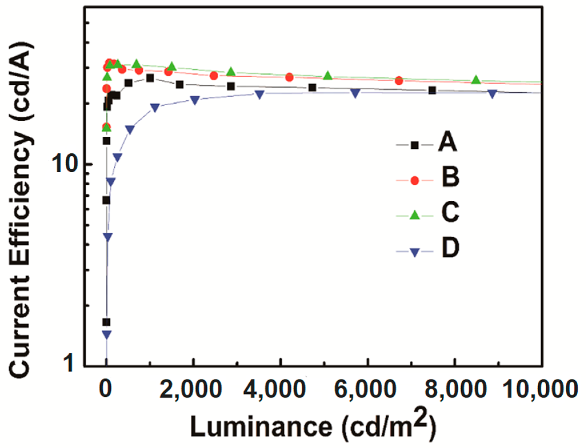
| Device A | (0.35, 0.48) | 3.89 | 26.7/26.6/23.9/22.6 | 12.7/11.0/10.4/10.1 |
| Device B | (0.36, 0.49) | 3.56 | 30.7/29.0/26.6/24.9 | 14.3/13.4/11.1/10.3 |
| Device C | (0.38, 0.54) | 3.38 | 31.0/30.7/27.2/25.5 | 13.1/12.4/10.8/10.1 |
| Device D | (0.36, 0.52) | 3.54 | 22.7/18.4/22.5/22.5 | 9.4/ 8.1/9.2/9.2 |
© 2019 by the authors. Licensee MDPI, Basel, Switzerland. This article is an open access article distributed under the terms and conditions of the Creative Commons Attribution (CC BY) license (http://creativecommons.org/licenses/by/4.0/).
Share and Cite
Sheng, R.; Gao, Y.; Li, A.; Duan, Y.; Zhao, Y.; Zheng, J.; Chen, P. Reduced Efficiency Roll-Off in White Phosphorescent Organic Light-Emitting Diodes Based on Double Emission Layers. Molecules 2019, 24, 211. https://doi.org/10.3390/molecules24010211
Sheng R, Gao Y, Li A, Duan Y, Zhao Y, Zheng J, Chen P. Reduced Efficiency Roll-Off in White Phosphorescent Organic Light-Emitting Diodes Based on Double Emission Layers. Molecules. 2019; 24(1):211. https://doi.org/10.3390/molecules24010211
Chicago/Turabian StyleSheng, Ren, Ying Gao, Asu Li, Yu Duan, Yi Zhao, Jie Zheng, and Ping Chen. 2019. "Reduced Efficiency Roll-Off in White Phosphorescent Organic Light-Emitting Diodes Based on Double Emission Layers" Molecules 24, no. 1: 211. https://doi.org/10.3390/molecules24010211