RF and Microwave Communications
(Closed)
A topical collection in Sensors (ISSN 1424-8220). This collection belongs to the section "Communications".
Viewed by 48200
Share This Topical Collection
Editor
 Dr. Ángela María Coves Soler
Dr. Ángela María Coves Soler
E-Mail
Website
Collection Editor
Department of Communications Engineering, Miguel Hernández University of Elche, Elche, Spain
Interests: microwave technology; optical; electromagnetic waves; antennas
Topical Collection Information
Dear Colleagues,
The increasing impact of the next generations of communications systems is noticeable throughout society, for example, in 5G and satellite communications, advanced on-demand TV and video services, automotive radars, sensing and RFID systems, navigation and remote observation systems, safety/security applications, or biomedical sensors, among others. Related to this, in recent years, we have witnessed strong development in RF and microwave communication components due to increasing requirements related to higher transmission speeds, higher degrees of miniaturization, reliability and connectivity issues (reconfiguration capabilities), advanced electrical responses, as well as capabilities for supporting wider bandwidths and higher power levels. All these new features demand the development of new and advanced technological solutions.
The aim of this Topical Collection is to highlight innovative developments with respect to the current and future applications of RF and microwave communications. Topics include but are not limited to the following:
- passive devices (filters, multiplexers, couplers, dividers/combiners, hybrids, resonators);
- active components (integrated active and tunable filters, power amplifiers, oscillators and mixers);
- RF microelectromechanical and micromachined components and subsystems;
- antennas;
- RFID systems;
- artificial intelligence and matching learning algorithms, implementations, and demonstrations for spectrum sensing;
- mobile edge networking;
- MIMO and array beam operations and the management,
- design, and optimization of RF/microwave components, circuits, and systems;
- in situ sensing, diagnostics, control, reconfiguration, and optimization of MHz to THz communication;
- sensing circuits and systems;
Dr. Ángela María Coves Soler
Collection Editor
Manuscript Submission Information
Manuscripts should be submitted online at www.mdpi.com by registering and logging in to this website. Once you are registered, click here to go to the submission form. Manuscripts can be submitted until the deadline. All submissions that pass pre-check are peer-reviewed. Accepted papers will be published continuously in the journal (as soon as accepted) and will be listed together on the collection website. Research articles, review articles as well as short communications are invited. For planned papers, a title and short abstract (about 100 words) can be sent to the Editorial Office for announcement on this website.
Submitted manuscripts should not have been published previously, nor be under consideration for publication elsewhere (except conference proceedings papers). All manuscripts are thoroughly refereed through a single-blind peer-review process. A guide for authors and other relevant information for submission of manuscripts is available on the Instructions for Authors page. Sensors is an international peer-reviewed open access semimonthly journal published by MDPI.
Please visit the Instructions for Authors page before submitting a manuscript.
The Article Processing Charge (APC) for publication in this open access journal is 2600 CHF (Swiss Francs).
Submitted papers should be well formatted and use good English. Authors may use MDPI's
English editing service prior to publication or during author revisions.
Keywords
- passive devices
- active components
- RF MEMs
- antennas
- RFID systems
- AI/ML algorithms
Published Papers (22 papers)
Open AccessArticle
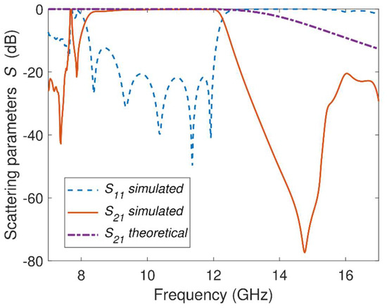
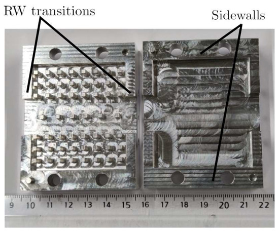
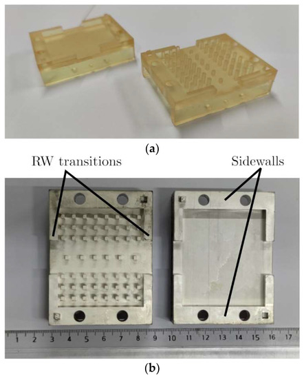
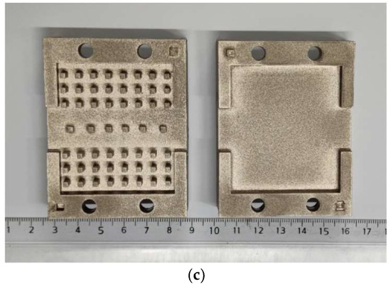
Compact Wideband Groove Gap Waveguide Bandpass Filters Manufactured with 3D Printing and CNC Milling Techniques
by
Clara Máximo-Gutierrez, Juan Hinojosa, José Abad-López, Antonio Urbina-Yeregui and Alejandro Alvarez-Melcon
Cited by 1 | Viewed by 1060
Abstract
This paper presents for the first time a compact wideband bandpass filter in groove gap waveguide (GGW) technology. The structure is obtained by including metallic pins along the central part of the GGW bottom plate according to an
n-order Chebyshev stepped impedance
[...] Read more.
This paper presents for the first time a compact wideband bandpass filter in groove gap waveguide (GGW) technology. The structure is obtained by including metallic pins along the central part of the GGW bottom plate according to an
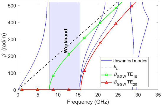
n-order Chebyshev stepped impedance synthesis method. The bandpass response is achieved by combining the high-pass characteristic of the GGW and the low-pass behavior of the metallic pins, which act as impedance inverters. This simple structure together with the rigorous design technique allows for a reduction in the manufacturing complexity for the realization of high-performance filters. These capabilities are verified by designing a fifth-order GGW Chebyshev bandpass filter with a bandwidth
BW = 3.7 GHz and return loss
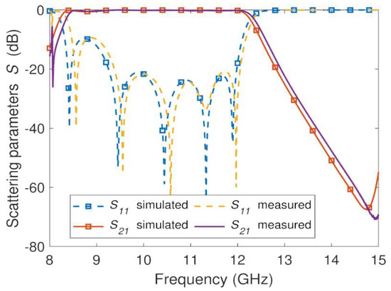
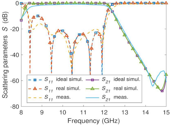
RL = 20 dB in the frequency range of the WR-75 standard, and by implementing it using computer numerical control (CNC) machining and three-dimensional (3D) printing techniques. Three prototypes have been manufactured: one using a computer numerical control (CNC) milling machine and two others by means of a stereolithography-based 3D printer and a photopolymer resin. One of the two resin-based prototypes has been metallized from a silver vacuum thermal evaporation deposition technique, while for the other a spray coating system has been used. The three prototypes have shown a good agreement between the measured and simulated
S-parameters, with insertion losses better than
IL = 1.2 dB. Reduced size and high-performance frequency responses with respect to other GGW bandpass filters were obtained. These wideband GGW filter prototypes could have a great potential for future emerging satellite communications systems.
Full article
►▼
Show Figures
Open AccessArticle
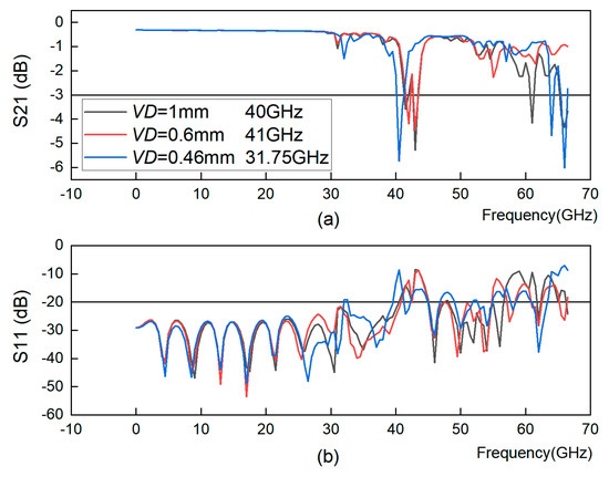
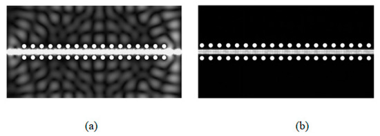
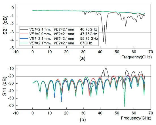
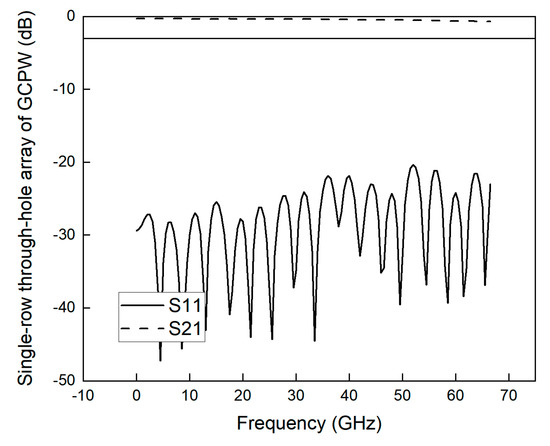
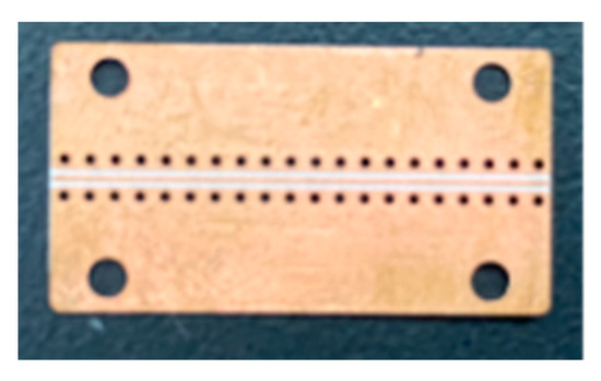
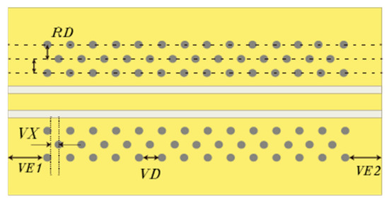
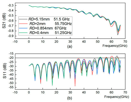
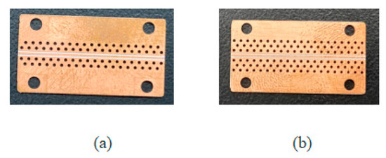
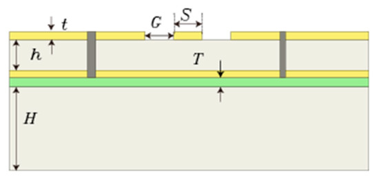
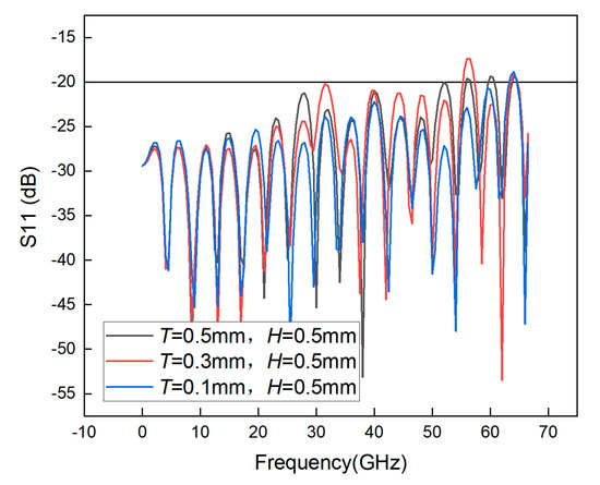
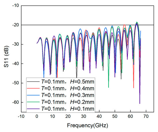
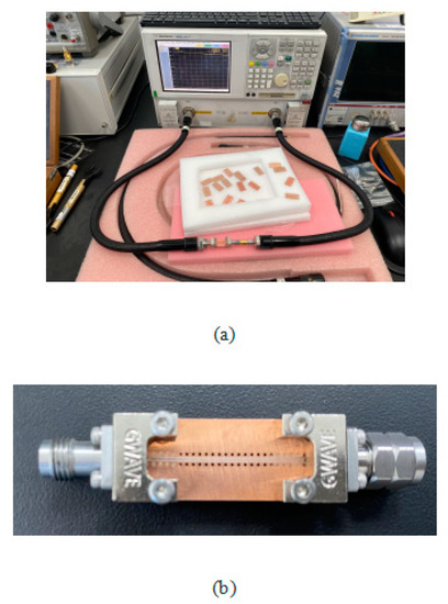
Method to Change the Through-Hole Structure to Broaden Grounded Coplanar Waveguide Bandwidth
by
Jiangmiao Zhu, Zhaotong Wan and Kejia Zhao
Viewed by 1432
Abstract
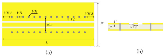
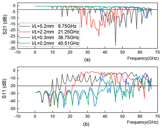
A grounded coplanar waveguide (GCPW), as a millimeter wave special transmission line, can be used to calibrate broadband oscilloscope probes. A method to change the through-hole structure to widen the GCPW is investigated in this paper. The effect of the through-hole array on
[...] Read more.
A grounded coplanar waveguide (GCPW), as a millimeter wave special transmission line, can be used to calibrate broadband oscilloscope probes. A method to change the through-hole structure to widen the GCPW is investigated in this paper. The effect of the through-hole array on the band-width of the GCPW is investigated and verified using COMSOL Multiphysics simulation software. Finally, the S-parameters of the fabricated GCPWs are measured by a vector network analyzer, and the results show that they have an insertion loss > −3 dB and return loss < −10 dB in the frequency range of DC to 60 GHz, which satisfies the design requirements.
Full article
►▼
Show Figures
Open AccessReview
A Review of Clothing Components in the Development of Wearable Textile Antennas: Design and Experimental Procedure
by
Aris Tsolis, Sofia Bakogianni, Chrysanthi Angelaki and Antonis A. Alexandridis
Cited by 9 | Viewed by 2371
Abstract
Wearable antenna systems have attracted significant research efforts during the last decade and a rich pool of review papers can be found in the literature. Each scientific work contributes to various fields of wearable technology focusing, mainly, on constructing materials, manufacturing techniques, targeting
[...] Read more.
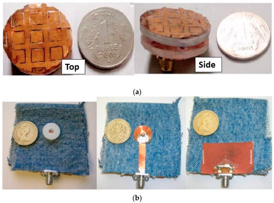
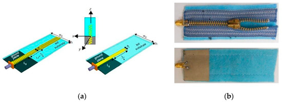
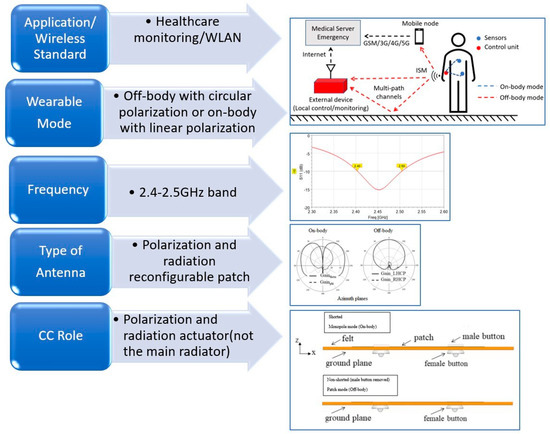
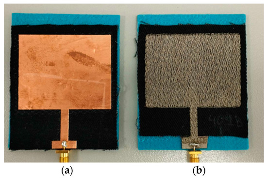
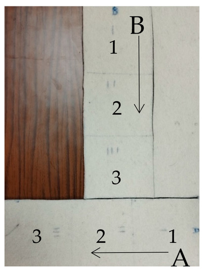
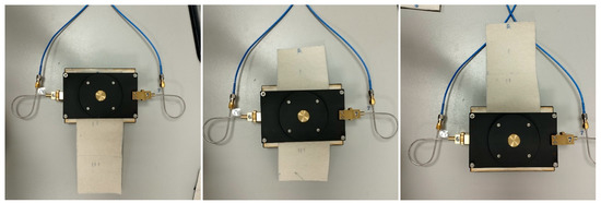
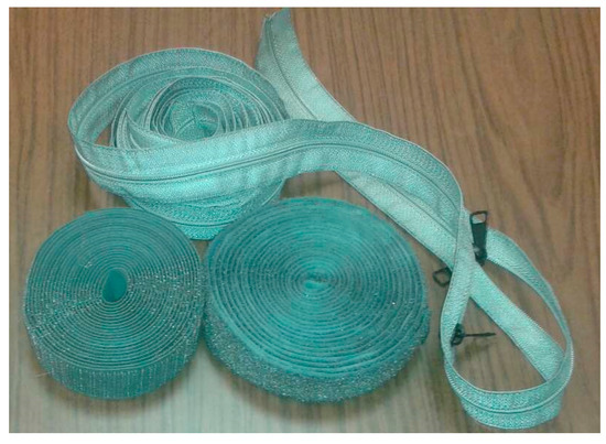
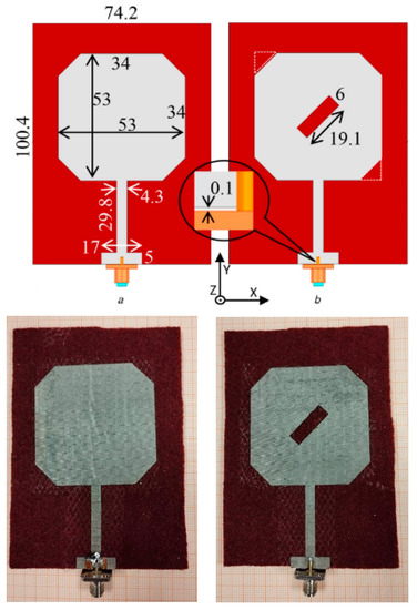
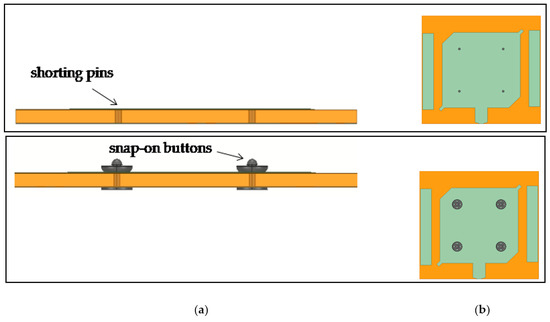
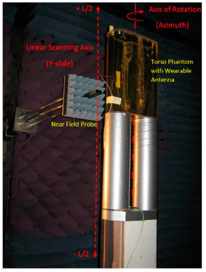
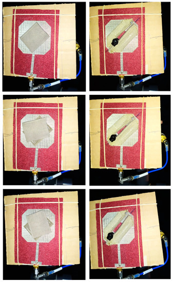
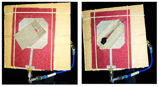
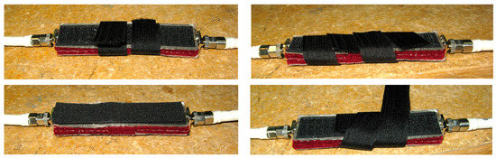
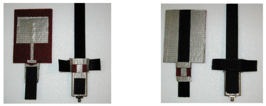
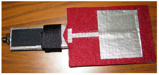
Wearable antenna systems have attracted significant research efforts during the last decade and a rich pool of review papers can be found in the literature. Each scientific work contributes to various fields of wearable technology focusing, mainly, on constructing materials, manufacturing techniques, targeting applications, and miniaturization methods. In this review paper, we examine the use of clothing components in wearable antenna technology. By the term “clothing components” (CC), dressmaking accessories/materials such as buttons, snap-on buttons, Velcro tapes, or zips are considered. In light of their utilization in the development of wearable antennas, the clothing components can play a triple role: (i) that of a clothing item, (ii) that of an antenna part or the main radiator, and (iii) that of an integration means of the antennas into clothes. One of their advantages is that they consist of conductive elements, integrated into the clothes, which can be effectively exploited as operating parts of wearable antennas. This review paper includes classification and description of the clothing components used so far in the development of wearable textile antennas with an emphasis on designs, applications and performance. Furthermore, a step-by-step design procedure for textile antennas that use clothing components as a functional part of their configuration is recorded, reviewed, and described in detail. The design procedure takes into account the detailed geometrical models required for the clothing components and the way they are embedded into the wearable antenna structure. In addition to the design procedure, aspects of experimental procedures (parameters, scenarios, and processes) that should be followed in wearable textile antennas with an emphasis on antennas that use clothing components (e.g., repeatability measurements) are presented. Finally, the potential of textile technology through the application of clothing components into wearable antennas is outlined.
Full article
►▼
Show Figures
Open AccessArticle
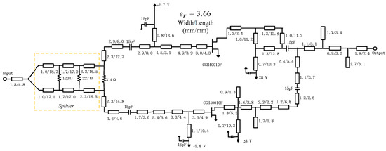
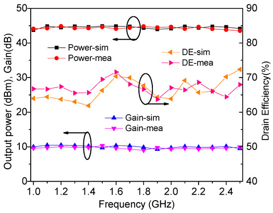
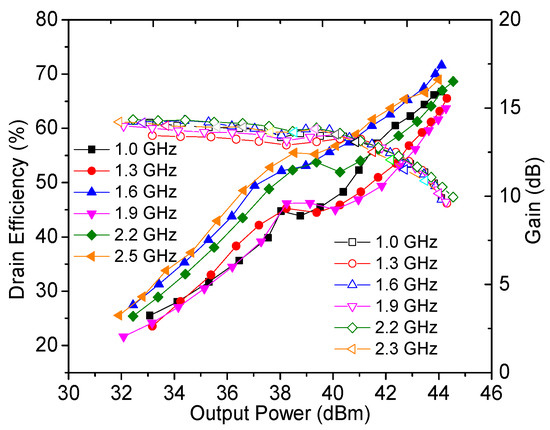
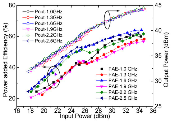
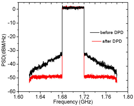
A High-Relative-Bandwidth Doherty Power Amplifier with Modified Load Modulation Network for Wireless Communications
by
Haipeng Zhu, Zhiwei Zhang, Chao Gu and Xuefei Xuan
Cited by 1 | Viewed by 1385
Abstract
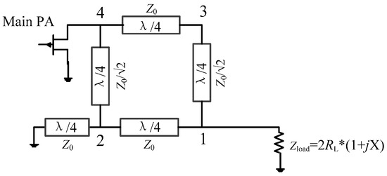
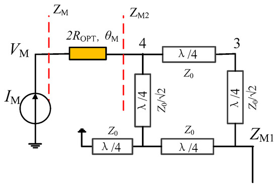
This paper presents a novel load modulation network to realize a broadband Doherty power amplifier (DPA). The proposed load modulation network consists of two generalized transmission lines and a modified coupler. A comprehensive theoretical analysis is carried out to explain the operation principles
[...] Read more.
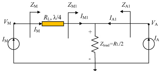
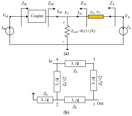
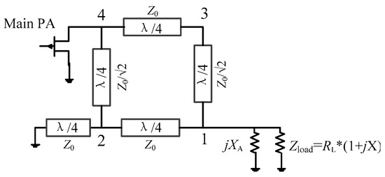
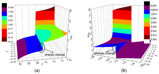
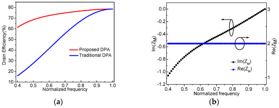
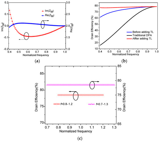
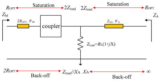
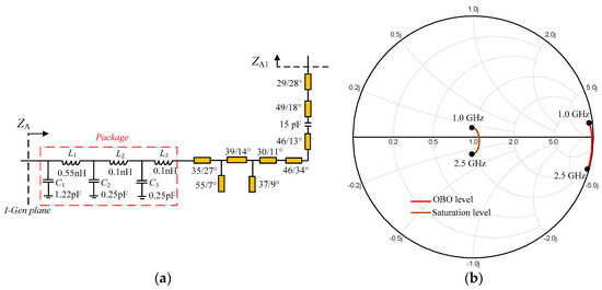
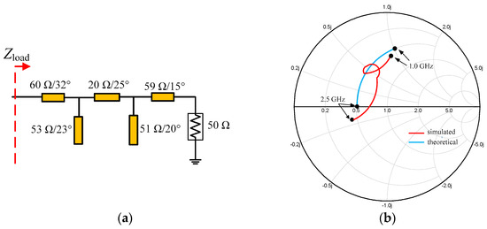
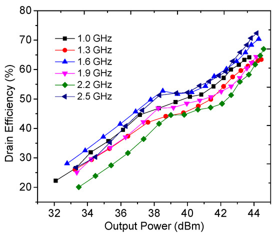
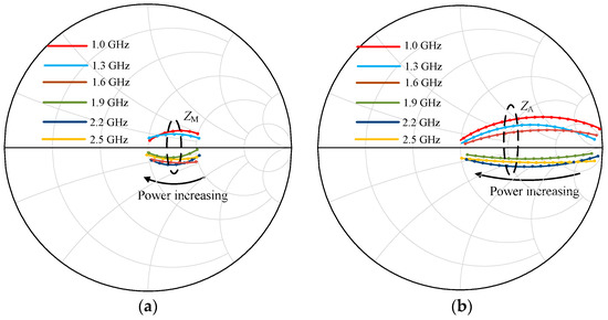
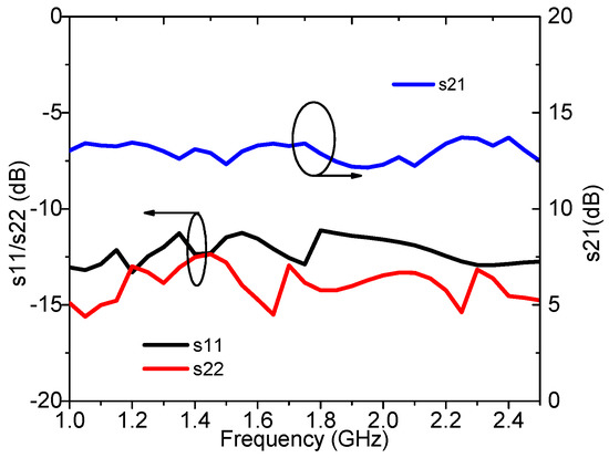
This paper presents a novel load modulation network to realize a broadband Doherty power amplifier (DPA). The proposed load modulation network consists of two generalized transmission lines and a modified coupler. A comprehensive theoretical analysis is carried out to explain the operation principles of the proposed DPA. The analysis of the normalized frequency bandwidth characteristic shows that a theoretical relative bandwidth of approximately 86% can be obtained across a normalized frequency range of 0.4–1.0. The complete design process that allows the design of the large-relative-bandwidth DPA based on derived parameter solutions is presented. A broadband DPA operating between 1.0 GHz and 2.5 GHz was fabricated for validation. Measurements demonstrate that the DPA can deliver an output power of 43.9–44.5 dBm with a drain efficiency of 63.7–71.6% in the 1.0–2.5 GHz frequency band at the saturation level. Moreover, a drain efficiency of 45.2–53.7% can be obtained at the 6 dB power back-off level.
Full article
►▼
Show Figures
Open AccessArticle
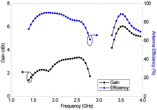
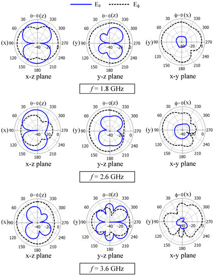
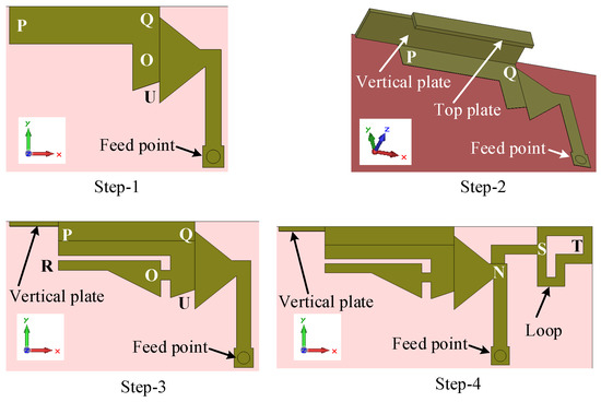
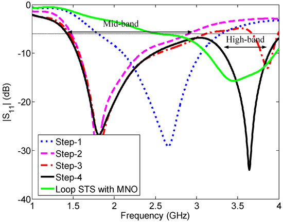
Antennas for Licensed Shared Access in 5G Communications with LTE Mid- and High-Band Coverage
by
Khaled M. Morshed, Debabrata K. Karmokar and Karu P. Esselle
Cited by 2 | Viewed by 1836
Abstract
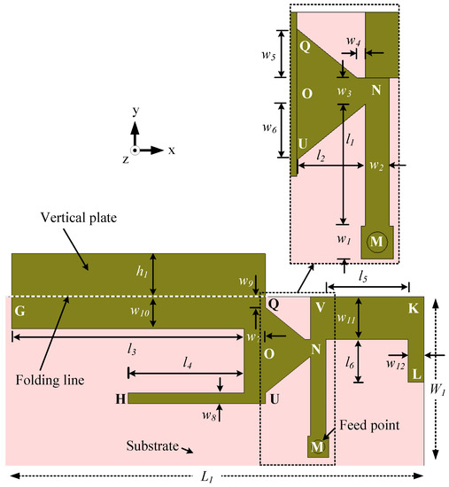
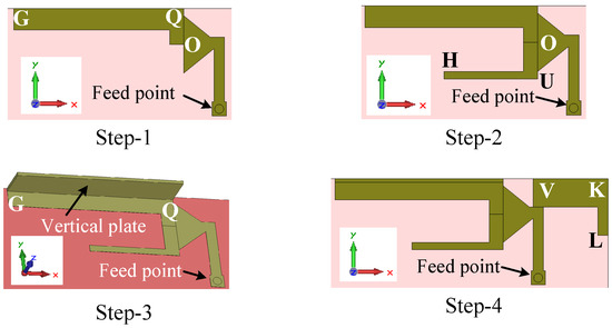
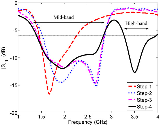
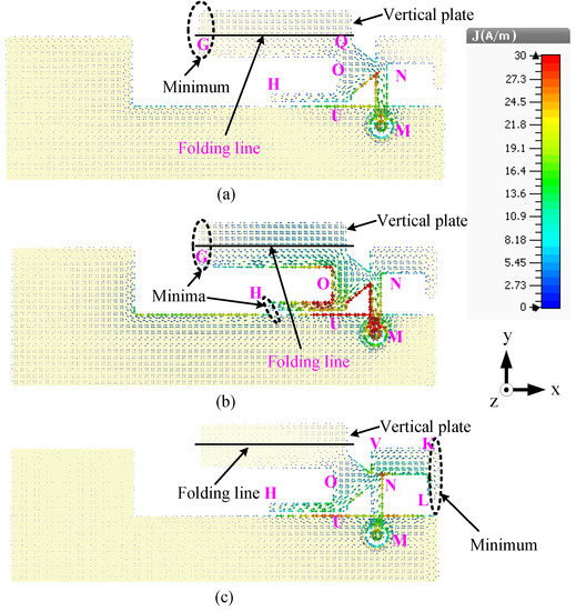
Two novel antennas are presented for mobile devices to enable them to access both licensed shared access (LSA) bands (1452–1492 and 2300–2400 MHz) and all the long-term evolution (LTE) mid (1427–2690 MHz) and high (3400–3800 MHz) bands, together with the GSM1800, GSM1900, UMTS,
[...] Read more.
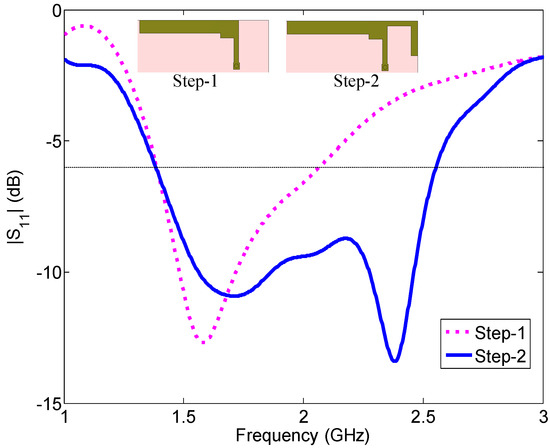
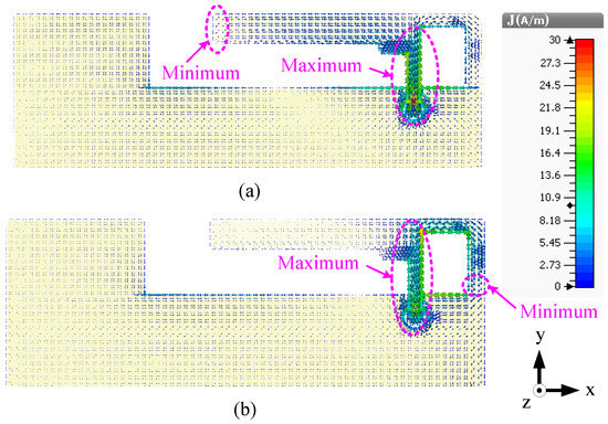
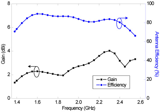
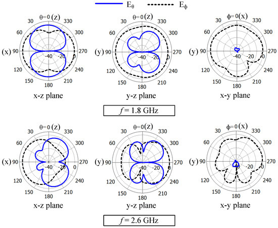
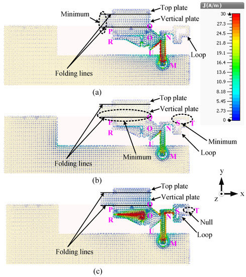
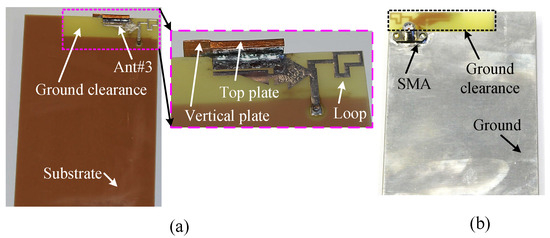
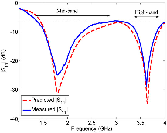
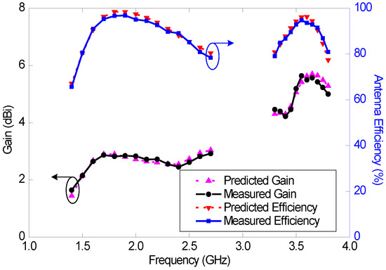
Two novel antennas are presented for mobile devices to enable them to access both licensed shared access (LSA) bands (1452–1492 and 2300–2400 MHz) and all the long-term evolution (LTE) mid (1427–2690 MHz) and high (3400–3800 MHz) bands, together with the GSM1800, GSM1900, UMTS, and 3.3 GHz WiMAX bands. These antennas do not require any passive or active lumped elements for input impedance matching. One of them is a dual-band antenna and the other is a wideband antenna. Both antennas have high efficiency in all the LSA bands, as well as the mid- and high-LTE bands, and nearly omnidirectional radiation patterns in the mid band. In the high band, the radiation patterns of the wideband antenna are less directional than those of the dual-band antenna. The wideband antenna was fabricated and tested and the measurements demonstrated that it had good wideband performance in a wide frequency range from 1.37 to 4 GHz, covering all the above-mentioned bands.
Full article
►▼
Show Figures
Open AccessCommunication
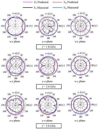
A High-Temperature Superconducting Bandpass Dual-Mode Filter with Tunable Relative Bandwidth and Center Frequency
by
Zhaojiang Shang, Liejun Shen, Jianyong Huang and Huibin Zhang
Viewed by 1050
Abstract
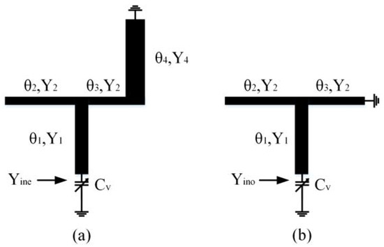
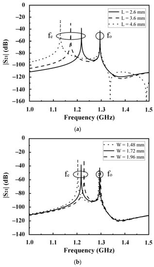
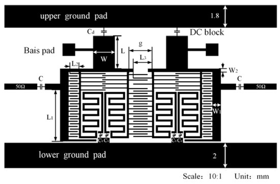
This study proposes a high-temperature superconducting (HTS) bandpass filter with a continuously tunable bandwidth and center frequency. The proposed filter combines several gallium arsenide varactors and a dual-mode resonator (DMR). The even and odd modes of the DMR can be tuned simultaneously using
[...] Read more.
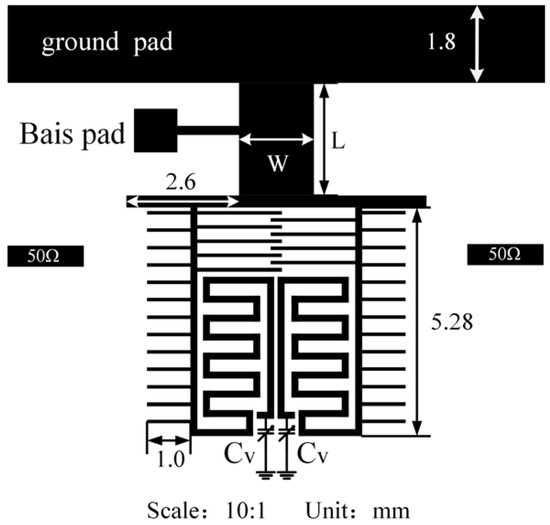
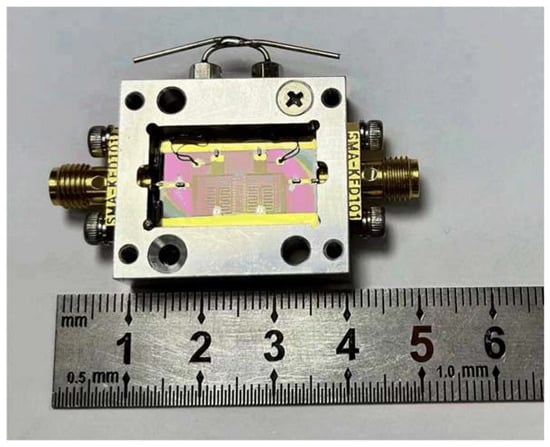
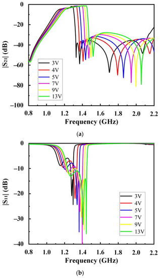
This study proposes a high-temperature superconducting (HTS) bandpass filter with a continuously tunable bandwidth and center frequency. The proposed filter combines several gallium arsenide varactors and a dual-mode resonator (DMR). The even and odd modes of the DMR can be tuned simultaneously using a single bias voltage. The capacitive value of varactors in the circuit is tuned continuously under continuous voltage and frequency tunability. External couplings and the interstage can be realized using an interdigital coupling structure; a fixed capacitor is added to the feeder to improve its coupling strength. A low-insertion loss within the band is obtained using HTS technology. Additionally, the proposed filter is etched on a 0.5 mm-thick MgO substrate and combined with YBCO thin films for demonstration. For the as-fabricated device, the tuning frequency range of 1.22~1.34 GHz was 9.4%; the 3-dB fractional bandwidth was 12.95~17.39%, and the insertion loss was 2.28~3.59 dB. The simulation and experimental measurement results were highly consistent.
Full article
►▼
Show Figures
Open AccessArticle
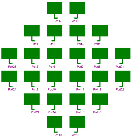
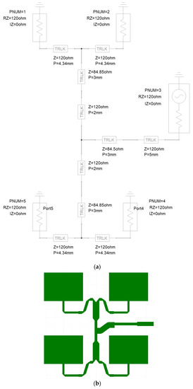
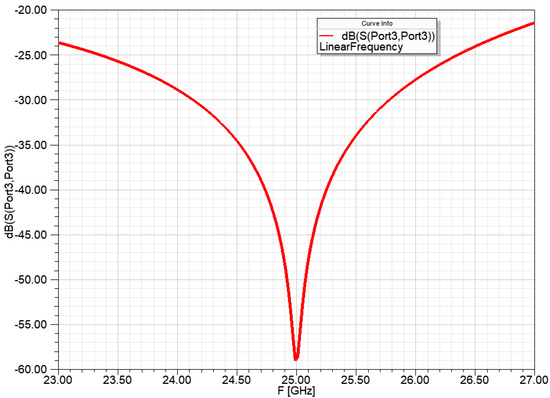
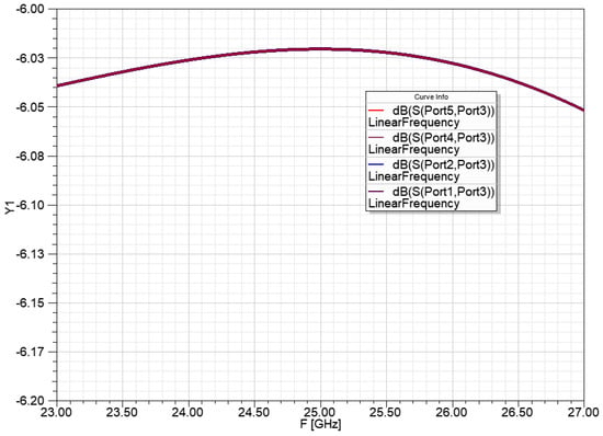
Microstrip Antenna Development for Radar Sensor
by
Lajos Nagy
Cited by 3 | Viewed by 2034
Abstract
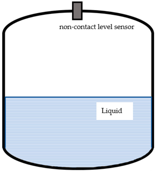
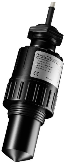
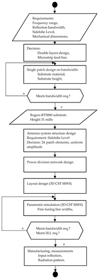
Tank level measurement is an important research area in radar technology. Level measurement using radar technology is a safe solution even under extreme process conditions, such as high pressure, temperature, and vapors. Special antennas are required to meet electromagnetic requirements such as high
[...] Read more.
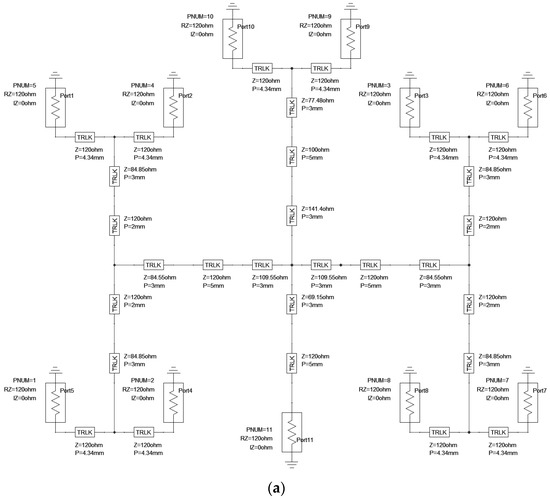
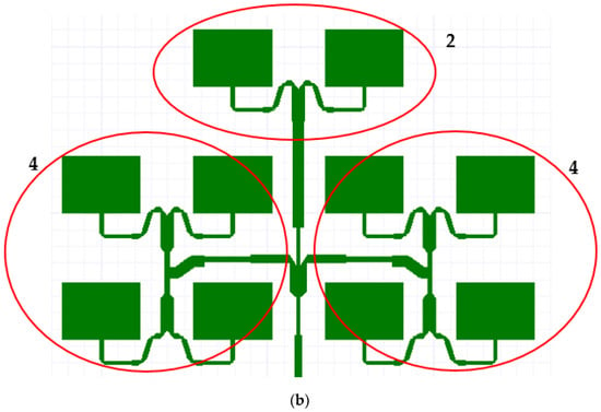
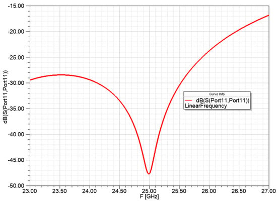
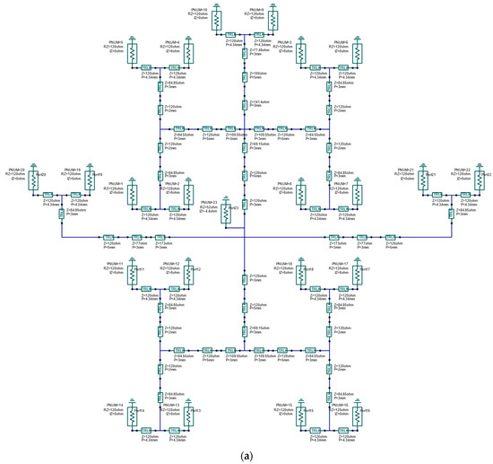
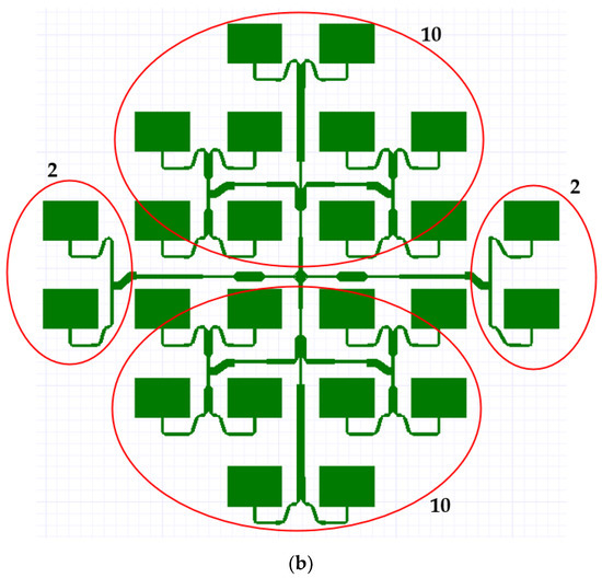
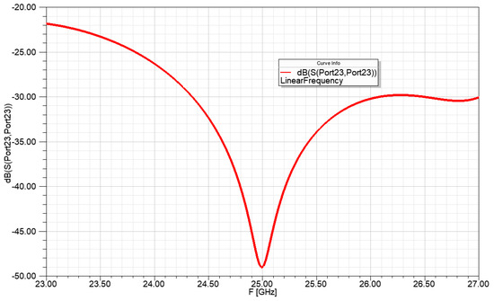
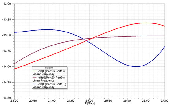
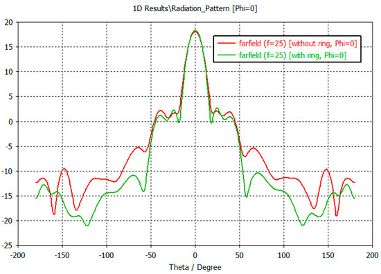
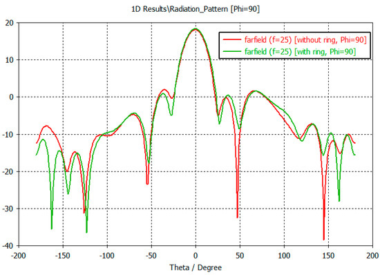
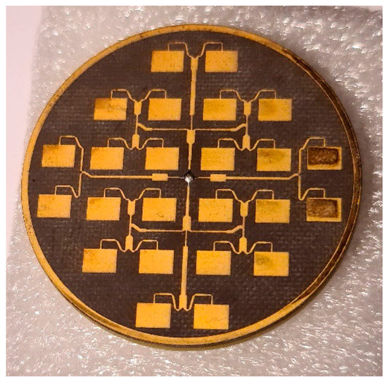
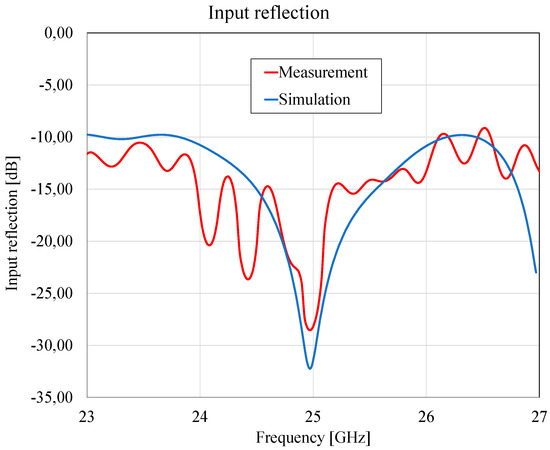
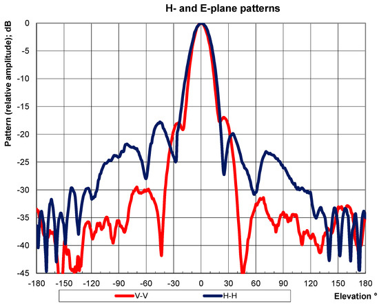
Tank level measurement is an important research area in radar technology. Level measurement using radar technology is a safe solution even under extreme process conditions, such as high pressure, temperature, and vapors. Special antennas are required to meet electromagnetic requirements such as high gain, low sidelobe level, and high bandwidth. Another requirement is a small size and good manufacturability of the antenna. One promising solution is the use of microstrip antennas for tank-level measurements. This paper presents a special microstrip antenna, that meets the main requirements in addition to a circular antenna layout, which fills optimally the tank hatch. To do this, we created a special antenna layout with a suitable feeding network and added an optimized ring around the antenna system, which significantly reduces the sidelobe level. The center frequency of the antenna is 25 GHz with a 1 GHz bandwidth.
Full article
►▼
Show Figures
Open AccessArticle
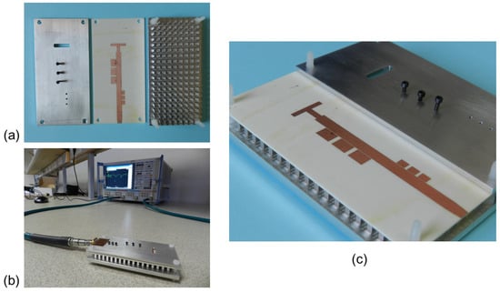
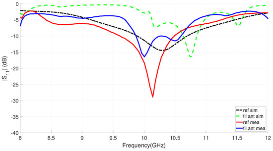
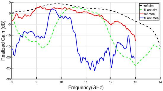
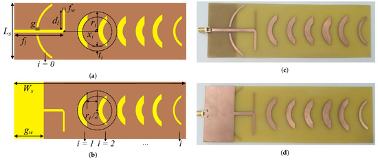
Inverted Microstrip Gap Waveguide Filtering Antenna Based on Coplanar EBG Resonators
by
Luis Inclán-Sánchez
Cited by 2 | Viewed by 2000
Abstract
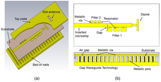
A new simple design of an inverted microstrip Gap Waveguide filtering antenna integrated with two stopband filters is proposed in this work. In order to simultaneously provide filtering and radiating functions, we use the direct integration approach to cascade two periodic sets of
[...] Read more.
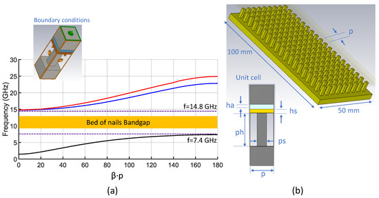
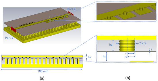
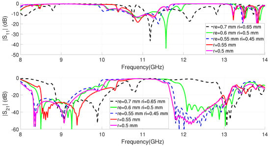
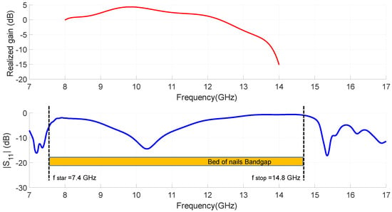
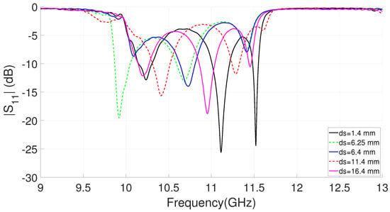
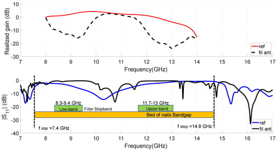
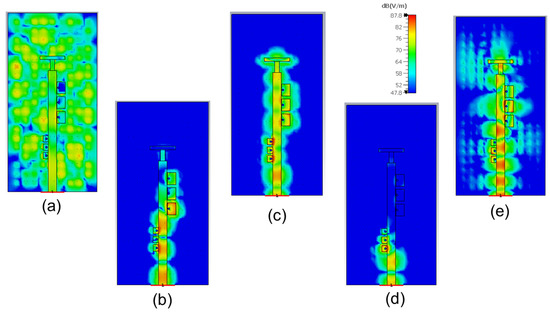
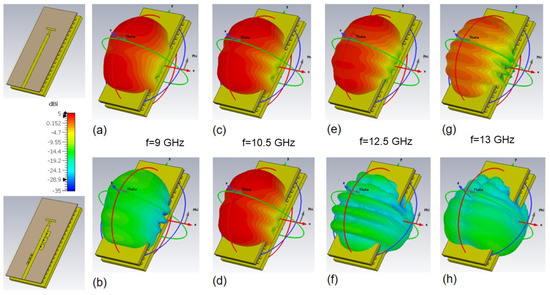
A new simple design of an inverted microstrip Gap Waveguide filtering antenna integrated with two stopband filters is proposed in this work. In order to simultaneously provide filtering and radiating functions, we use the direct integration approach to cascade two periodic sets of coplanar coupled EBG resonators with a slot antenna. The analysis shows that the filters can be easily adjusted in the same feeding layer of the antenna, without extra circuitry and without modifying the lines. EBG-filters are compact and offer great flexibility in determining the frequency, width and selectivity of the rejected bands. Experimental results for an X-band filtering antenna prototype are provided showing a 7.3% transmission band centered at 10.2 GHz and a realized gain peak of 2.1 dBi. The measurements demonstrate the filtering capability of the proposed antenna, achieving rejection levels greater than 12 dB and 20 dB for the bands below and above the operation band. The proposed low-complexity design offers good performance as a filter and as an antenna, showing the essential advantages of the Gap Waveguide Technology, including low losses, self-packaging and limited cost. This work demonstrates the possibility of integrating the new coplanar EBG-filters into future Gap Waveguide antenna designs to avoid unwanted radiation, to reduce interfering signals or to provide high isolation in multiband systems.
Full article
►▼
Show Figures
Open AccessArticle
Implementation of a WSN for Environmental Monitoring: From the Base Station to the Small Sensor Node
by
Tiago Emanuel Oliveira, João Ricardo Reis and Rafael Ferreira Silva Caldeirinha
Cited by 3 | Viewed by 1638
Abstract
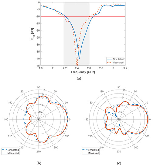
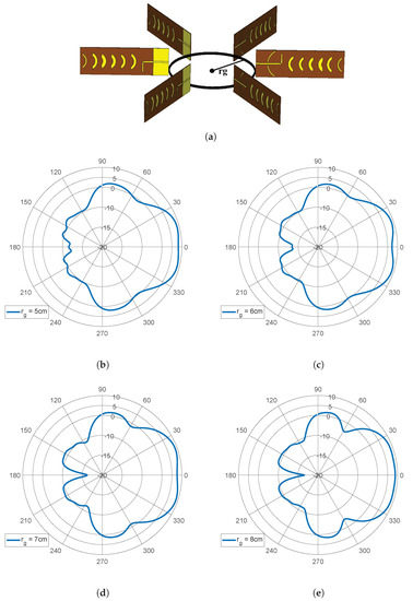
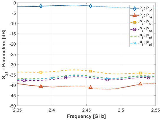
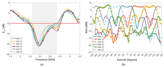
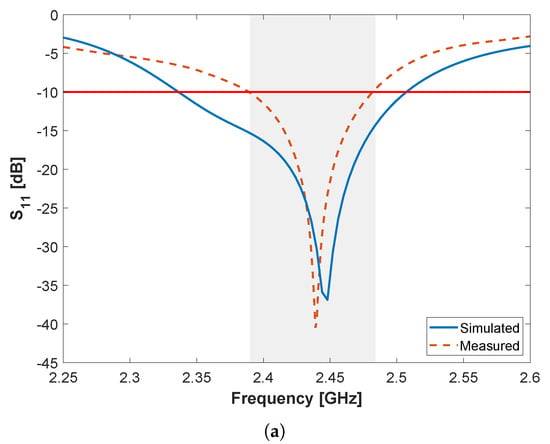
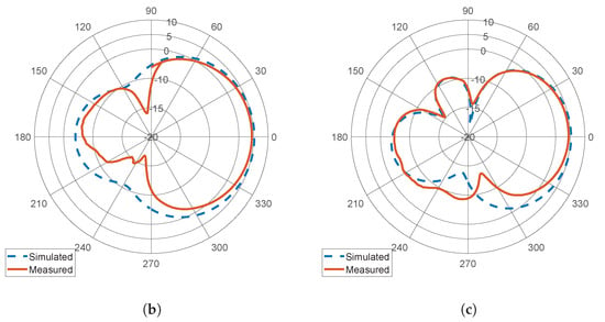
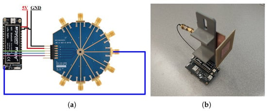
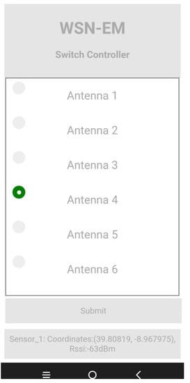
In this paper, the implementation of a Wireless Sensor Network (WSN) for environmental monitoring (EM) is presented. It includes the design, implementation and experimental characterization of a multi-sector base station (BS) antenna composed of several microstrip Quasi-Yagi elements and the implementation and experimental
[...] Read more.
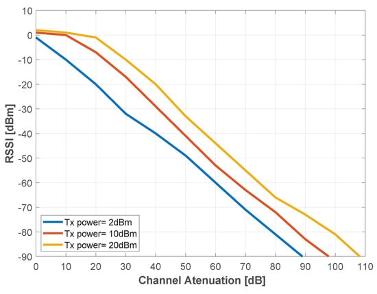
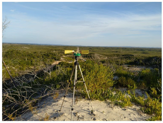
In this paper, the implementation of a Wireless Sensor Network (WSN) for environmental monitoring (EM) is presented. It includes the design, implementation and experimental characterization of a multi-sector base station (BS) antenna composed of several microstrip Quasi-Yagi elements and the implementation and experimental characterization of a reduced form factor antenna for the sensor nodes (SN). Subsequently, it reports the implementation of a WSN based on Lopy4 transceivers, using the developed BS and SN antennas. Finally, experimental results obtained on the field to evaluate the performance of the network in terms of maximum coverage distance and coverage area are presented. According to the field tests, the connectivity between the sensor nodes and the developed WSN base station is confirmed at distances above 3.5 km and for all the antenna sectors of the multi-sector BS attaining a 360
of field of view.
Full article
►▼
Show Figures
Open AccessArticle
Microstrip-Fed 3D-Printed H-Sectorial Horn Phased Array
by
Ivan Zhou, Lluís Pradell, José Maria Villegas, Neus Vidal, Miquel Albert, Lluís Jofre and Jordi Romeu
Cited by 2 | Viewed by 1881
Abstract
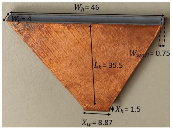
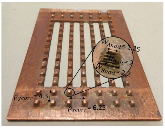
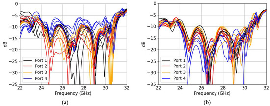
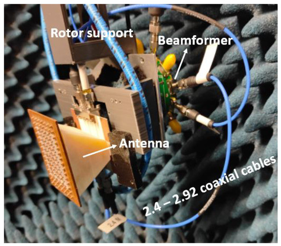
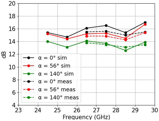
A 3D-printed phased array consisting of four H-Sectorial horn antennas of 200 g weight with an ultra-wideband rectangular-waveguide-to-microstrip-line transition operating over the whole LMDS and K bands (24.25–29.5 GHz) is presented. The transition is based on exciting three overlapped transversal patches that radiate
[...] Read more.
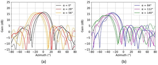
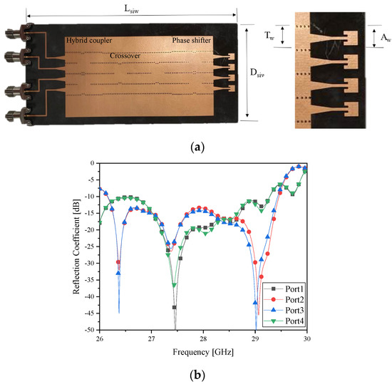
A 3D-printed phased array consisting of four H-Sectorial horn antennas of 200 g weight with an ultra-wideband rectangular-waveguide-to-microstrip-line transition operating over the whole LMDS and K bands (24.25–29.5 GHz) is presented. The transition is based on exciting three overlapped transversal patches that radiate into the waveguide. The transition provides very low insertion losses, ranging from 0.30 dB to 0.67 dB over the whole band of operation (23.5–30.4 GHz). The measured fractional bandwidth of the phased array including the transition was 20.8% (24.75–30.3 GHz). The antenna was measured for six different scanning angles corresponding to six different progressive phases
, ranging from 0° to 140° at the central frequency band of operation of 26.5 GHz. The maximum gain was found in the broadside direction
= 0°, with 15.2 dB and efficiency
= 78.5%, while the minimum was found for
= 140°, with 13.7 dB and
= 91.2%.
Full article
►▼
Show Figures
Open AccessFeature PaperArticle
Discussion and Analysis of Dumbbell Defect-Ground-Structure (DB-DGS) Resonators for Sensing Applications from a Circuit Theory Perspective
by
Lijuan Su, Paris Vélez, Jonathan Muñoz-Enano and Ferran Martín
Cited by 5 | Viewed by 2130
Abstract
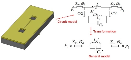
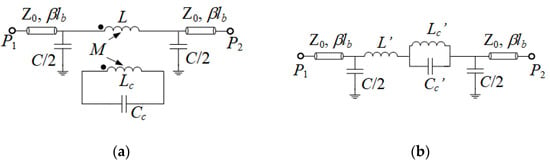
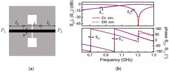
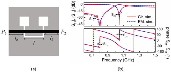
Microstrip transmission lines loaded with dumbbell defect-ground-structure (DB-DGS) resonators transversally oriented have been exhaustively used in microwave circuits and sensors. Typically, these structures have been modelled by means of a parallel LC resonant tank series connected to the host line. However, the inductance
[...] Read more.
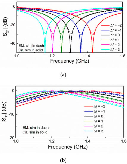
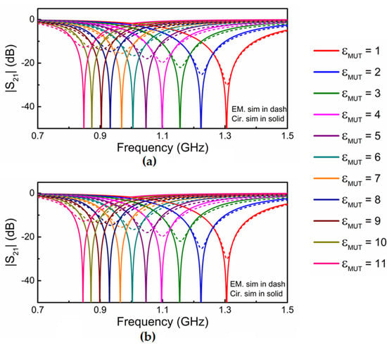
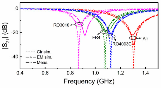
Microstrip transmission lines loaded with dumbbell defect-ground-structure (DB-DGS) resonators transversally oriented have been exhaustively used in microwave circuits and sensors. Typically, these structures have been modelled by means of a parallel LC resonant tank series connected to the host line. However, the inductance and capacitance of such model do not have a physical meaning, since this model is inferred by transformation of a more realistic model, where the DB-DGS resonator, described by means of a resonant tank with inductance and capacitance related to the geometry of the DB-DGS, is magnetically coupled to the host line. From parameter extraction, the circuit parameters of both models are obtained by considering the DB-DGS covered with semi-infinite materials with different dielectric constant. The extracted parameters are coherent and reveal that the general assumption of considering the simple LC resonant tank series-connected to the line to describe the DB-DGS-loaded line is reasonable with some caution. The implications on the sensitivity, when the structure is devoted to operating as a permittivity sensor, are discussed.
Full article
►▼
Show Figures
Open AccessArticle
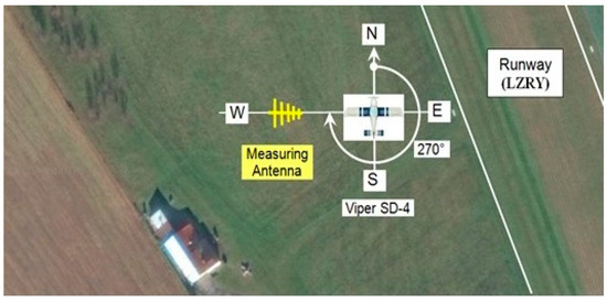
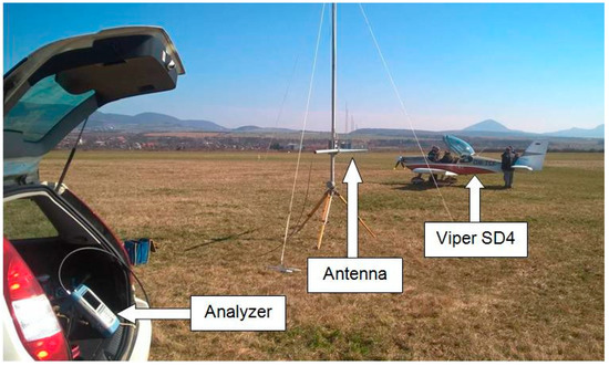
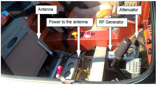
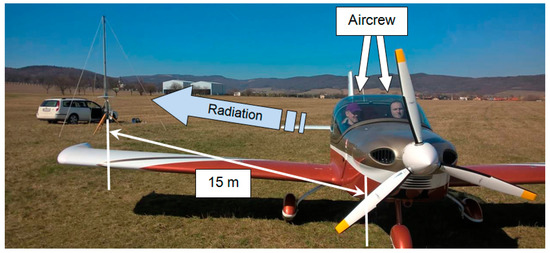
Airport Spatial Usability in Measuring the Spherical Antenna Properties on Small Aircraft
by
Ján Labun, Pavol Kurdel, Marek Češkovič, Alexey Nekrasov, Mária Gamcová and Natália Gecejová
Cited by 2 | Viewed by 1870
Abstract
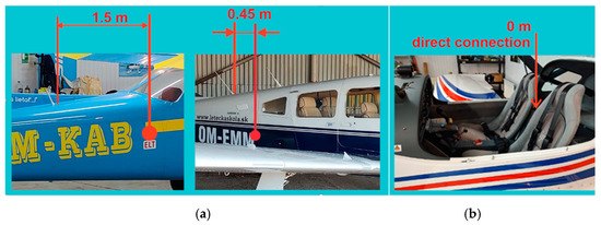
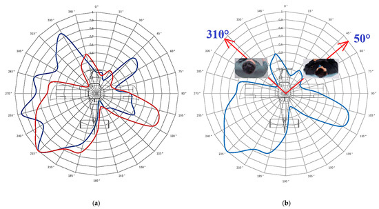
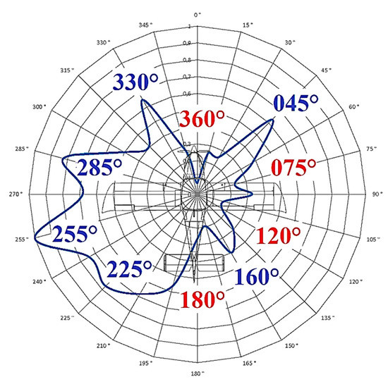
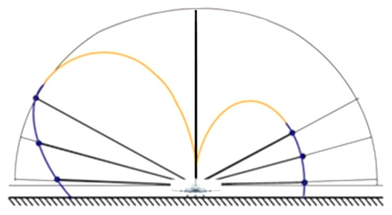
The strict safety requirements of air transport for nonstandard placement of electronic onboard systems require an innovative approach to the experimental verification of the placement of these devices. Particular attention is required to the location of these electronic devices’ antenna systems on the
[...] Read more.
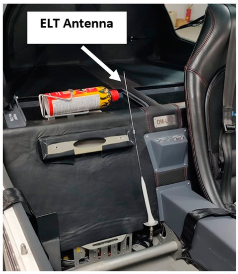
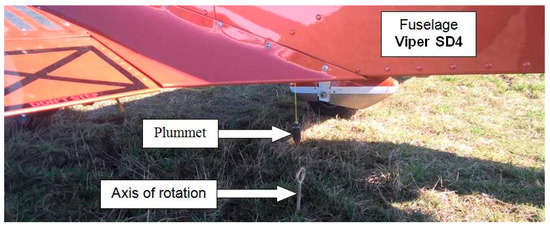
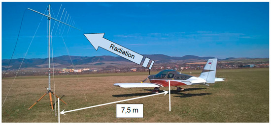
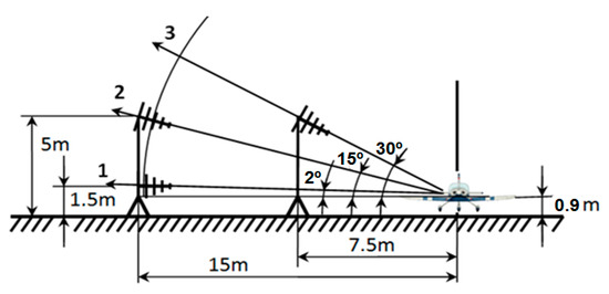
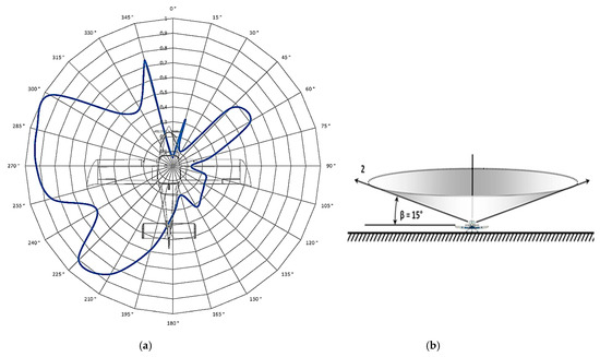
The strict safety requirements of air transport for nonstandard placement of electronic onboard systems require an innovative approach to the experimental verification of the placement of these devices. Particular attention is required to the location of these electronic devices’ antenna systems on the fuselage. A prerequisite for determining the location of the antenna and verifying its radiation is a thorough knowledge of the radio communication transmission of onboard electronic systems in cooperation with terrestrial or satellite systems. From this point of view, this article focuses on an innovative method of verifying the spherical radiation characteristics of the antenna of an onboard rescue system emergency locator transmitter (ELT) to assess its communication link with the Cospas-Sarsat satellite system. The measurement is performed on a small sports two-seater aircraft with an antenna placed in an unusual place in the aircraft’s cabin, between the seats. It was impossible to use a suitable nonreflective attenuation chamber for the measurement, so we present a method and procedure for this type of measurement in the open space of an airport. The achieved results prove the plausibility and reproducibility of the measurement. Furthermore, combining several polar radiation characteristics makes it possible to obtain an idea, even if only a part, of the spatial (spherical) radiation characteristic. This article presents a simple method of measuring the characteristics of aircraft antennas when it is not possible to use a suitable professional nonreflective attenuation chamber for measurements for various reasons. This method can also be used on other larger means of transport or other objects that experience the same problem.
Full article
►▼
Show Figures
Open AccessCommunication
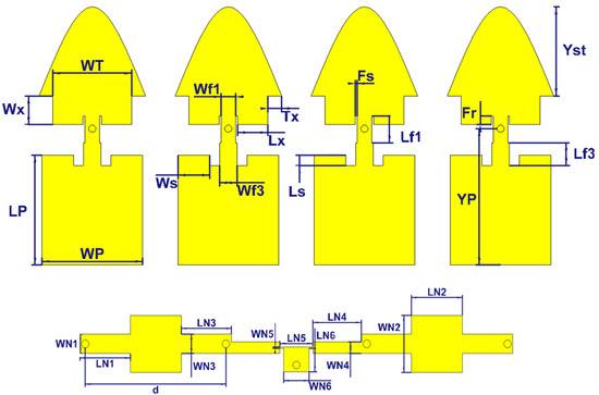
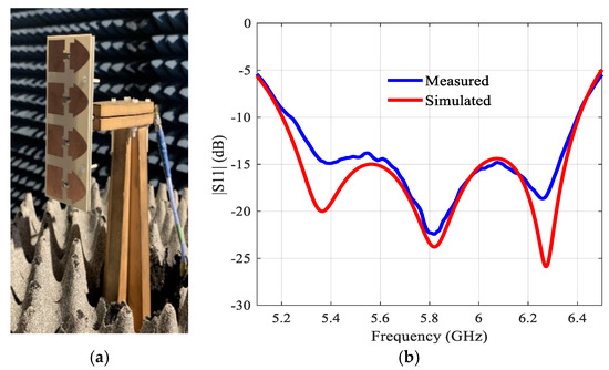
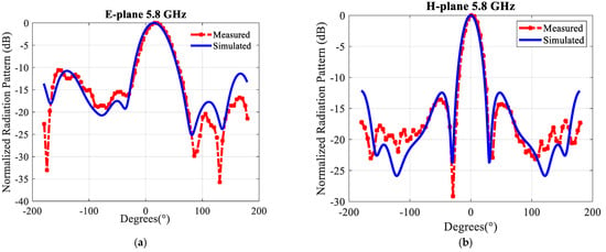
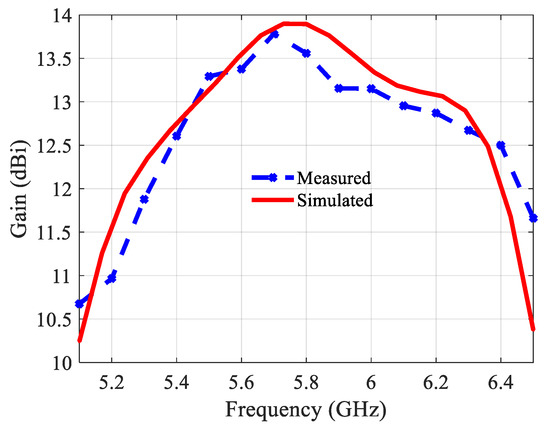
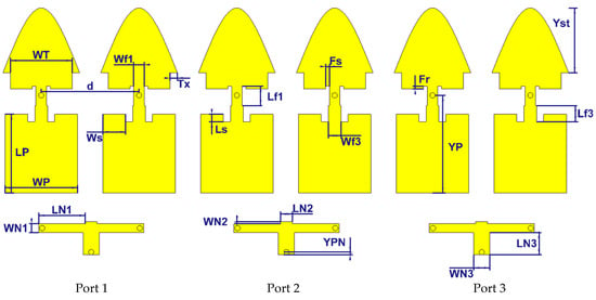
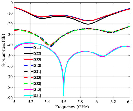
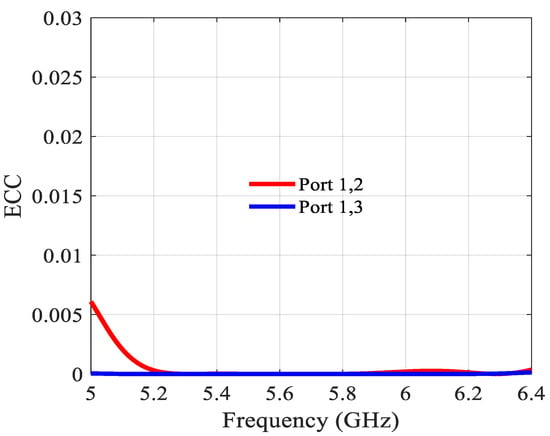
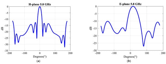
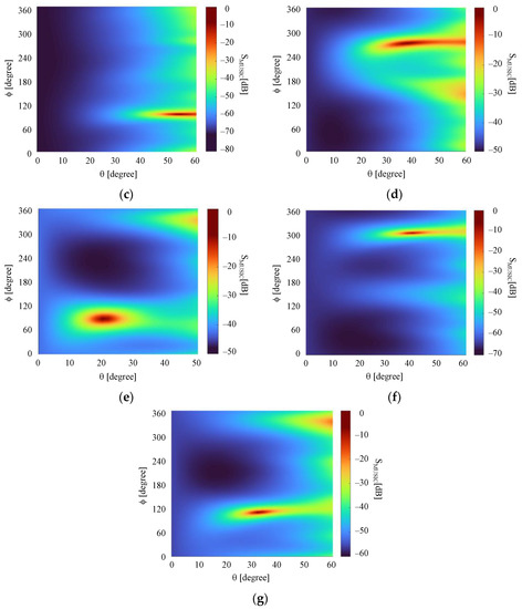
Design of a Novel Wideband Leaf-Shaped Printed Dipole Array Antenna Using a Parasitic Loop for High-Power Jamming Applications
by
Eunjung Kang, Tae Heung Lim, Seulgi Park and Hosung Choo
Cited by 1 | Viewed by 2162
Abstract
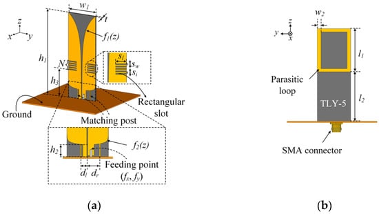
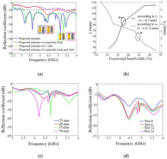
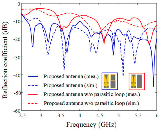
This paper proposes a novel wideband leaf-shaped printed dipole antenna sensor that uses a parasitic element to improve the impedance matching bandwidth characteristics for high-power jamming applications. The proposed antenna sensor consists of leaf-shaped dipole radiators, matching posts, rectangular slots, and a parasitic
[...] Read more.
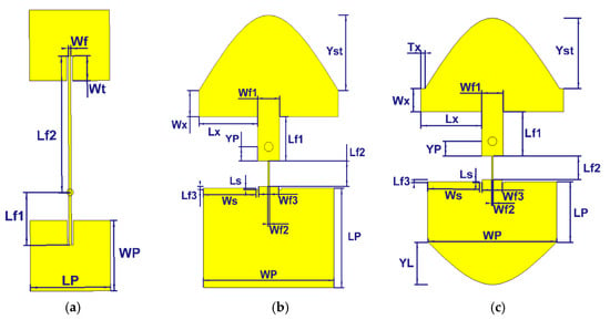
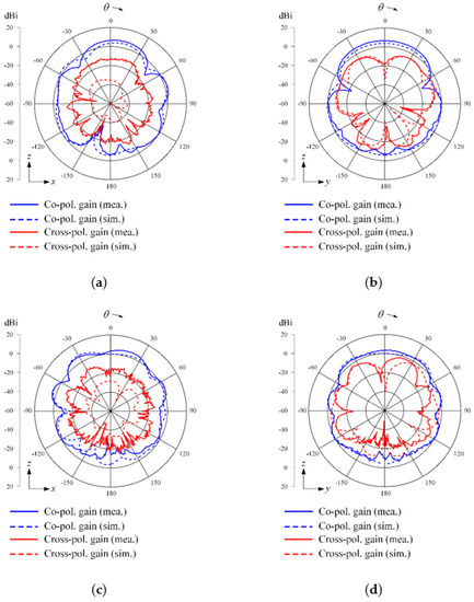
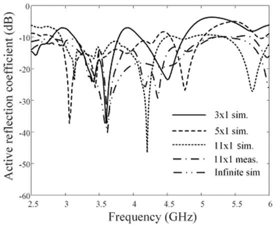
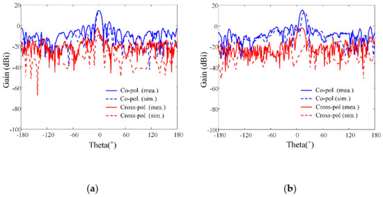
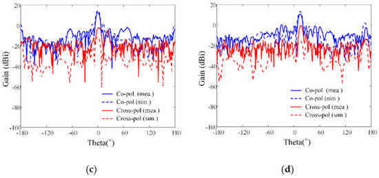
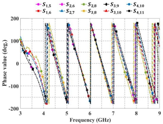
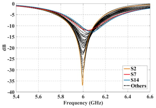
This paper proposes a novel wideband leaf-shaped printed dipole antenna sensor that uses a parasitic element to improve the impedance matching bandwidth characteristics for high-power jamming applications. The proposed antenna sensor consists of leaf-shaped dipole radiators, matching posts, rectangular slots, and a parasitic loop element. The leaf-shaped dipole radiators are designed with exponential curves to obtain a high directive pattern and are printed on a TLY-5 substrate for high-power durability. The matching posts, rectangular slots, and a parasitic loop element are used to enhance the impedance matching characteristics. The proposed antenna sensor has a measured fractional bandwidth of 66.7% at a center frequency of 4.5 GHz. To confirm the array antenna sensor characteristics, such as its active reflection coefficients (ARCs) and beam steering gains, the proposed single antenna sensor is extended to an 11 × 1 uniform linear array. The average values of the simulated and measured ARCs from 4.5 to 6 GHz are −13.4 dB and −14.7 dB. In addition, the measured bore-sight array gains of the co-polarization are 13.4 dBi and 13.7 dBi at 4 GHz and 5 GHz, while those of the cross-polarizations are −4.9 dBi and −3.4 dBi, respectively. When the beam is steered at a steering angle,
θ0, of 15°, the maximum measured array gains of the co-polarization are 12.2 dBi and 10.3 dBi at 4 GHz and 5 GHz, respectively.
Full article
►▼
Show Figures
Open AccessArticle
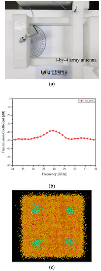
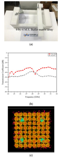
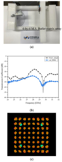
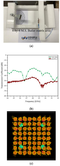
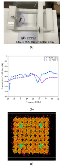
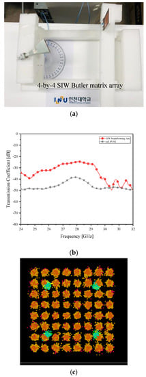
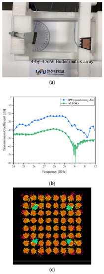
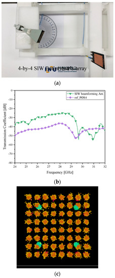
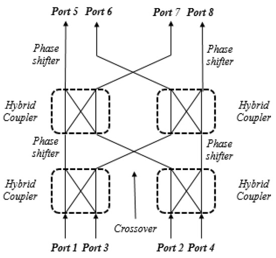
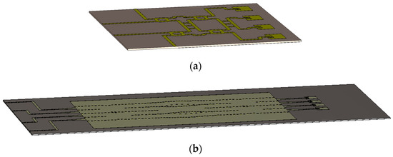
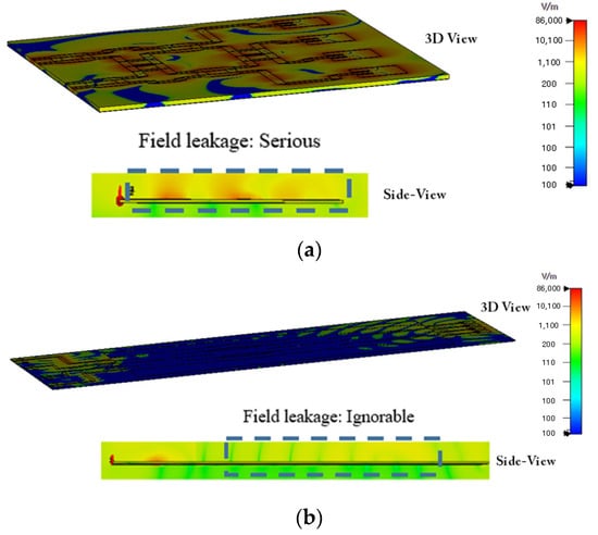
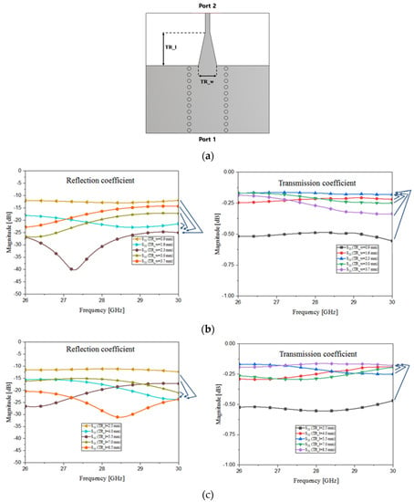
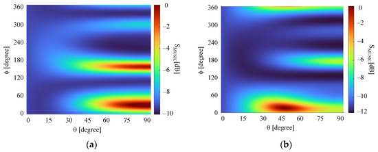
Investigation on Beam Alignment of a Microstrip-Line Butler Matrix and an SIW Butler Matrix for 5G Beamforming Antennas through RF-to-RF Wireless Sensing and 64-QAM Tests
by
Munsu Jeon, Yejune Seo, Junghyun Cho, Changhyeong Lee, Jiyeon Jang, Yejin Lee, Hyung-Wook Kwon and Sungtek Kahng
Cited by 4 | Viewed by 3030
Abstract
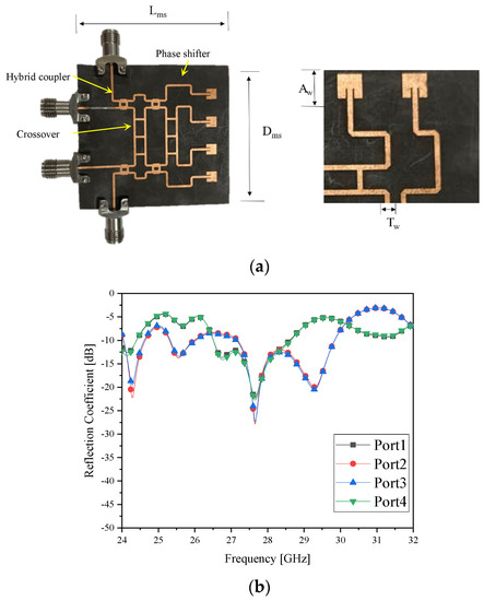
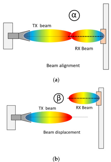
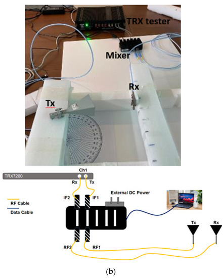
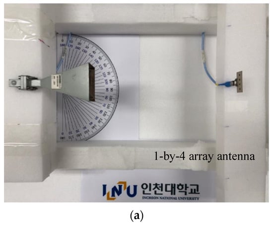
In this paper, an intuitive approach to assessing advantages of beamforming in 5G wireless communication is proposed as a novel try and practical demonstration of importance of alignment between the transmitter’s and receiver’s beams working in millimeter-wave frequency bands. Since the diffraction loss
[...] Read more.
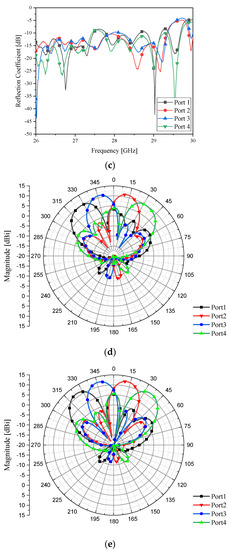
In this paper, an intuitive approach to assessing advantages of beamforming in 5G wireless communication is proposed as a novel try and practical demonstration of importance of alignment between the transmitter’s and receiver’s beams working in millimeter-wave frequency bands. Since the diffraction loss of millimeter-wave signals matters seriously in propagation, the effects of the misalignment and alignment between beams need to be checked for, which was conducted with a horn antenna and the 4 × 4 Butler matrix which mimic the relationship of the base station and handset antennas. Designing and using the microstrip-line and the substrate integrated waveguide (SIW) Butler matrices, RF-to-RF wireless connectivity between the horn and the microstrip line beamformer as case 1 and the horn and the SIW beamformer as case 2, concerning the changing angle of the beam from either of the two Butler matrices, was tested, showing over 12 dB enhancement in received power. This direct electromagnetic link test was accompanied by examining 64-QAM constellations for beam-angle changing from −30° to +30° for the two cases, where the error vector magnitude in the QAM-diagram becomes less than 10% by beam-alignment for the changing angle.
Full article
►▼
Show Figures
Open AccessArticle
Coherently Radiating Periodic Structures to Reduce the Number of Phase Shifters in a 2-D Phased Array
by
Elizvan Juárez, Marco A. Panduro, David H. Covarrubias and Alberto Reyna
Cited by 4 | Viewed by 1557
Abstract
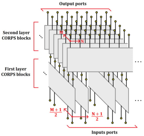
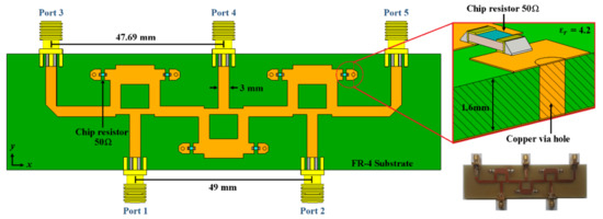
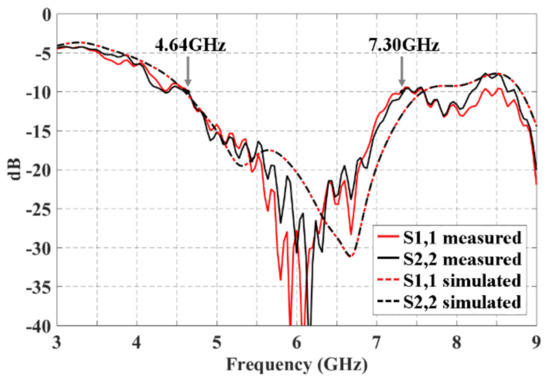
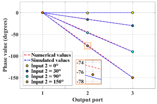
This paper illustrates the application of CORPS (coherently radiating periodic structures) for feeding 2-D phased arrays with a reduced number of phase shifter (PS) devices. Three design configurations using CORPS are proposed for 2-D phased arrays. The design model of phased array for
[...] Read more.
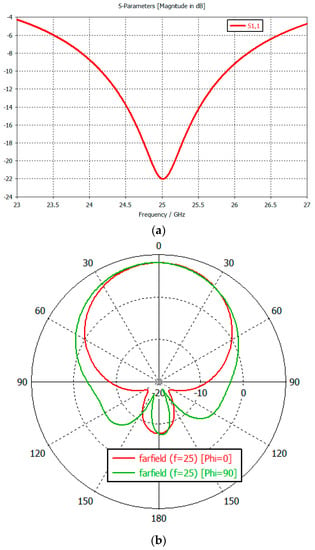
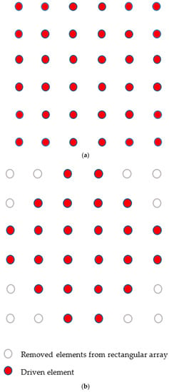
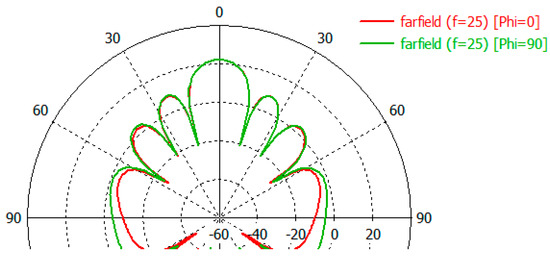
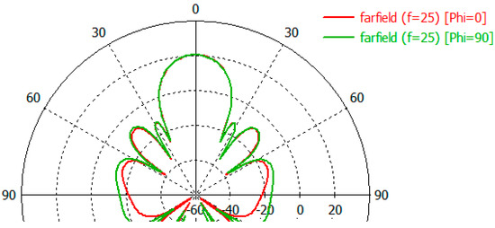
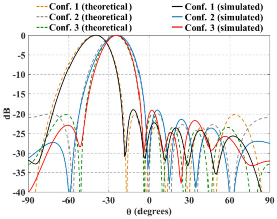
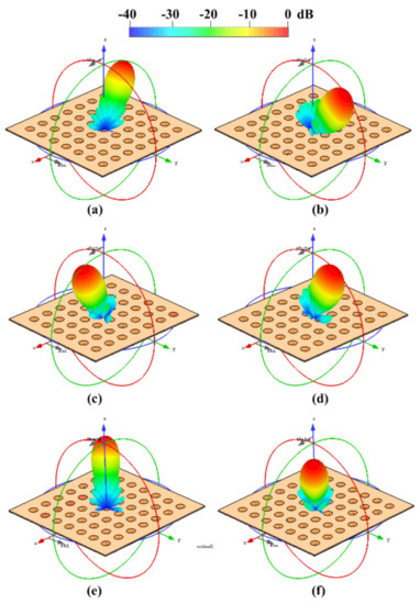
This paper illustrates the application of CORPS (coherently radiating periodic structures) for feeding 2-D phased arrays with a reduced number of phase shifter (PS) devices. Three design configurations using CORPS are proposed for 2-D phased arrays. The design model of phased array for these configurations considers the cophasal excitation required for this structure to set a strategic way for feeding the antenna elements and reducing the number of PS devices. Blocks of 2 × 3 and 4 × 7 CORPS networks depending on the configuration in the 2-D phased array are set strategically in the feeding network to generate the cophasal excitation required in the antenna elements. These design configurations used for feeding the antenna elements in the planar array geometry provide several advantages with respect to others in the scanning capability and the reduction of the number of PS devices of the array system. The full-wave simulation results for the proposed configurations in 2-D phased arrays provide a reduction in the number of PSs of until 69% for a scanning range of ±25° in elevation and ±40° in azimuth. The application of the raised cosine amplitude distribution could generate radiation patterns with a SLL_PEAK ≈ −19 dB and SLL_PEAK ≈ −23 dB for the design proposed configurations in all the scanning range.
Full article
►▼
Show Figures
Open AccessArticle
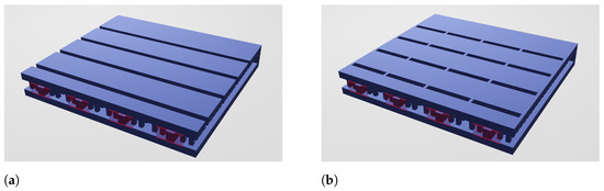
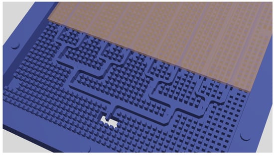
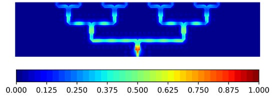
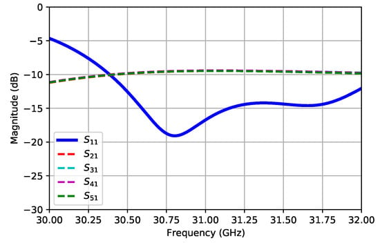
On the Use of Ridge Gap Waveguide Technology for the Design of Transverse Stub Resonant Antenna Arrays
by
Javier Benavides-Vazquez, Jose-Luis Vazquez-Roy and Eva Rajo-Iglesias
Viewed by 2019
Abstract
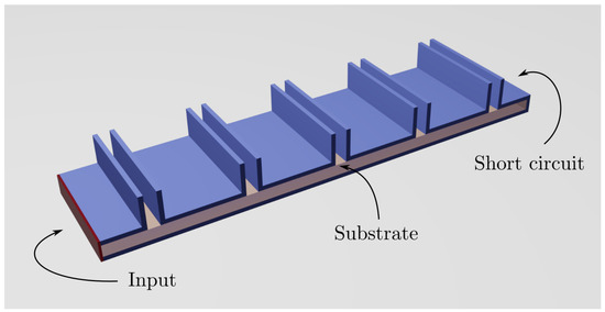
This paper presents some considerations on the design of a novel antenna consisting of the combination of a transverse stubs (TS) array excited by Ridge Gap Waveguides (RGWs), as well as a discussion of the experimental results obtained from a prototype that was
[...] Read more.
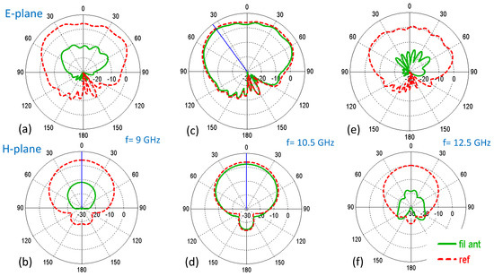
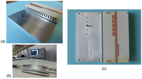
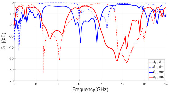
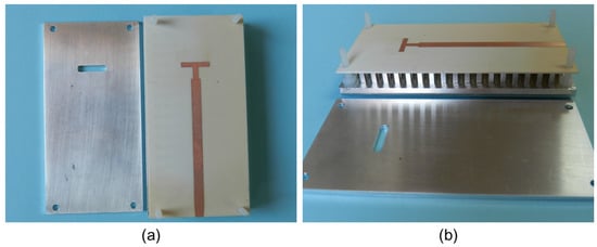
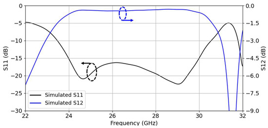
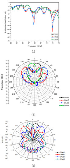
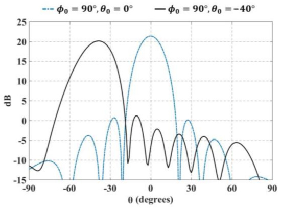
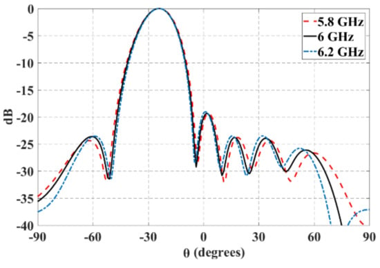
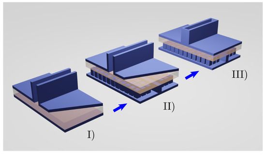
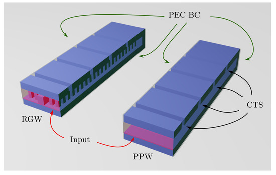
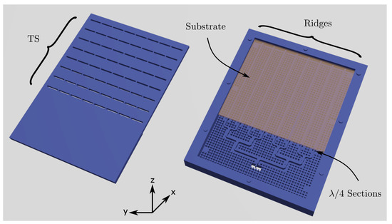
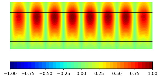
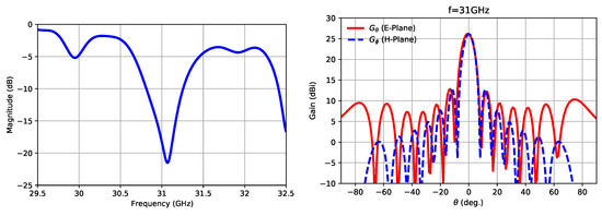
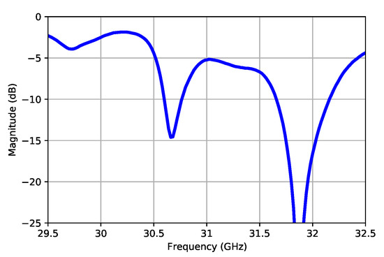
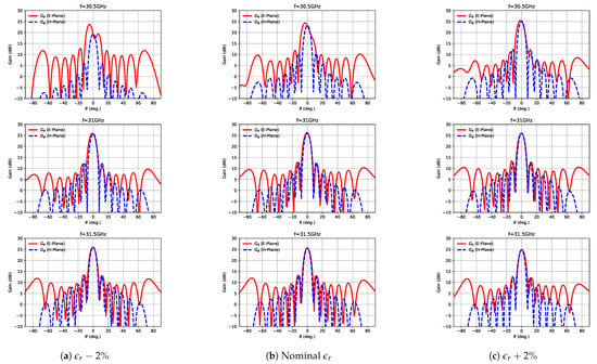
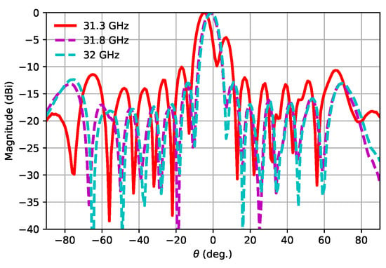
This paper presents some considerations on the design of a novel antenna consisting of the combination of a transverse stubs (TS) array excited by Ridge Gap Waveguides (RGWs), as well as a discussion of the experimental results obtained from a prototype that was manufactured and measured. A combination of Continuous Transverse Stubs (CTSs) is used as the starting point. Subsequently, the CTSs are modified to include some metallic blockers that split each CTS into a combination (array) of shorter TSs. This is performed in order to excite each individual TS column using a different RGW; thus, ensuring a close to uniform field distribution in the transverse plane of the TS arrays. Hence, the directivity of the antenna is increased. As a series-feed configuration is considered, the antenna keeps a resonant behaviour, having a narrow-band response. A Corporate Feeding Network (CFN) using the aforementioned RGW technology placed in the same layer as the rest of the antenna is included in the design. The radiating area of the antenna is, finally,
with a simulated peak gain of 26.2 dBi and a Side Lobe Level (SLL) below −13 dB. A prototype is manufactured and tested. The simulated and measured radiation patterns maintain similar shapes to those of the simulations, with very similar angular widths in both main planes, although the frequency corresponding to the highest directivity changes to 31.8 GHz. A matching bandwidth of 517 MHz and a gain of 24.5 is, finally, achieved at that frequency.
Full article
►▼
Show Figures
Open AccessArticle
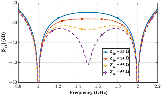
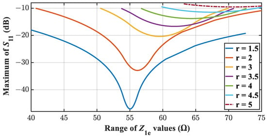
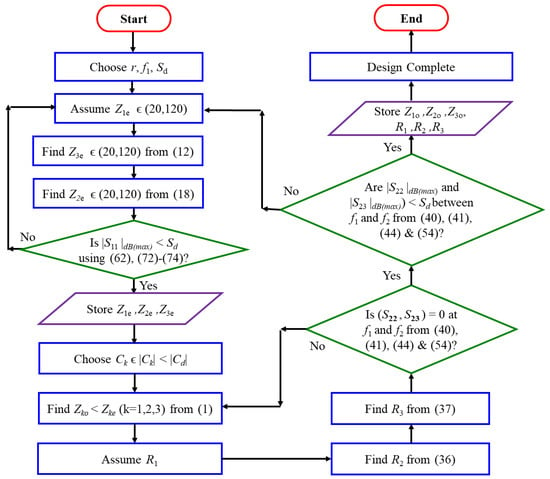
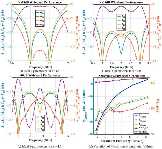
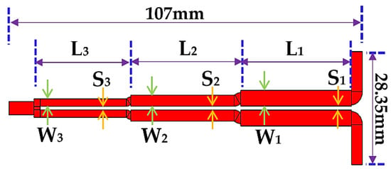
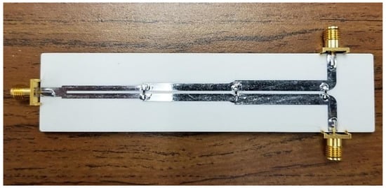
A Novel Analytical Design Technique for a Wideband Wilkinson Power Divider Using Dual-Band Topology
by
Asif I. Omi, Rakibul Islam, Mohammad A. Maktoomi, Christine Zakzewski and Praveen Sekhar
Cited by 6 | Viewed by 2732
Abstract
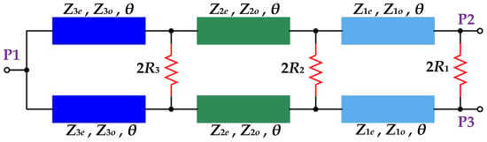
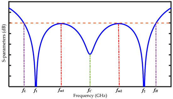
In this paper, a novel analytical design technique is presented to implement a coupled-line wideband Wilkinson power divider (WPD). The configuration of the WPD is comprised of three distinct coupled-line and three isolation resistors. A comprehensive theoretical analysis is conducted to arrive at
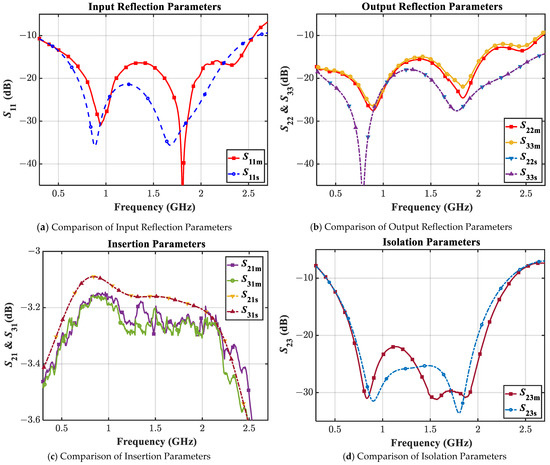
[...] Read more.
In this paper, a novel analytical design technique is presented to implement a coupled-line wideband Wilkinson power divider (WPD). The configuration of the WPD is comprised of three distinct coupled-line and three isolation resistors. A comprehensive theoretical analysis is conducted to arrive at a set of completely new and rigorous design equations utilizing the dual-band behavior of commensurate transmission lines. Further, the corresponding S-parameters equations are also derived, which determine the wideband capability of the proposed WPD. To validate the proposed design concept, a prototype working at the resonance frequencies of 0.9 GHz and 1.8 GHz is designed and fabricated using 60 mils thick Rogers’ RO4003C substrate. The measured result of the fabricated prototype exhibits an excellent input return loss > 16.4 dB, output return loss > 15 dB, insertion loss < 3.30 dB and a remarkable isolation > 22 dB within the band and with a 15 dB and 10 dB references provide a fractional bandwidth of 110% and 141%, respectively.
Full article
►▼
Show Figures
Open AccessArticle
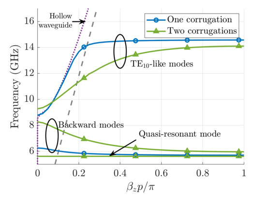
Study of Forward and Backward Modes in Double-Sided Dielectric-Filled Corrugated Waveguides
by
Pilar Castillo-Tapia, Francisco Mesa, Alexander Yakovlev, Guido Valerio and Oscar Quevedo-Teruel
Cited by 6 | Viewed by 1890
Abstract
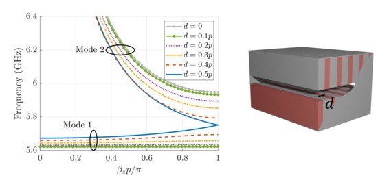
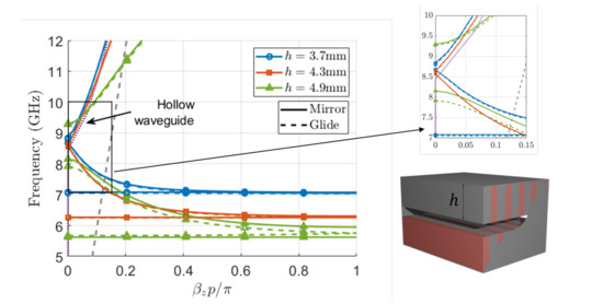
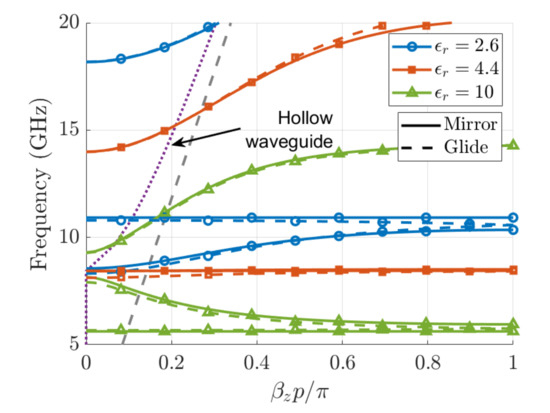
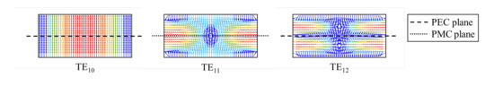
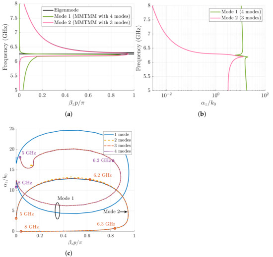
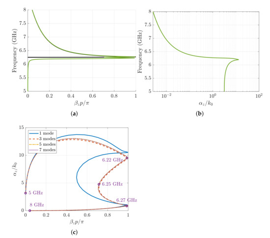
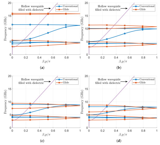
This work studies the propagation characteristics of a rectangular waveguide with aligned/misaligned double-sided dielectric-filled metallic corrugations. Two modes are found to propagate in the proposed double-sided configuration below the hollow-waveguide cutoff frequency: a quasi-resonant mode and a backward mode. This is in contrast
[...] Read more.
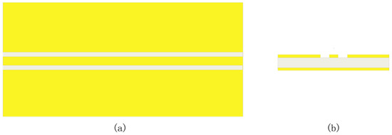
This work studies the propagation characteristics of a rectangular waveguide with aligned/misaligned double-sided dielectric-filled metallic corrugations. Two modes are found to propagate in the proposed double-sided configuration below the hollow-waveguide cutoff frequency: a quasi-resonant mode and a backward mode. This is in contrast to the single-sided configuration, which only allows for backward propagation. Moreover, the double-sided configuration can be of interest for waveguide miniaturization on account of the broader band of its backward mode. The width of the stopband between the quasi-resonant and backward modes can be controlled by the misalignment of the top and bottom corrugations, being null for the glide-symmetric case. The previous study is complemented with numerical results showing the impact of the height of the corrugations, as well as the filling dielectric permittivity, on the bandwidth and location of the appearing negative-effective-permeability band. The multi-modal transmission-matrix method has also been employed to estimate the rejection level and material losses in the structure and to determine which port modes are associated with the quasi-resonant and backward modes. Finally, it is shown that glide symmetry can advantageously be used to reduce the dispersion and broadens the operating band of the modes.
Full article
►▼
Show Figures
Open AccessArticle
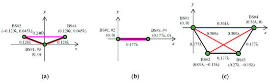
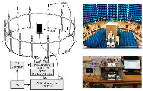
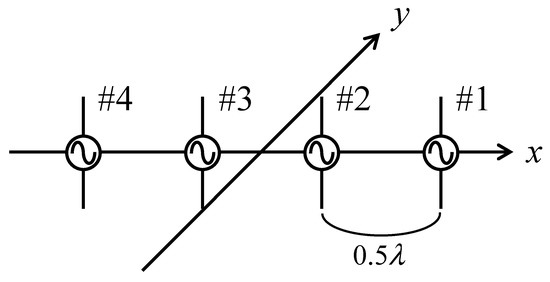
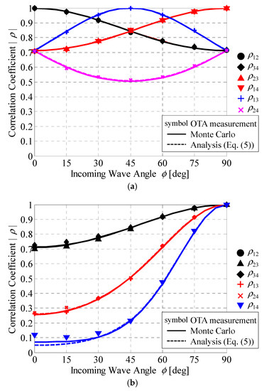
A Method of Implementing a 4 × 4 Correlation Matrix for Evaluating the Uplink Channel Properties of MIMO Over-the-Air Apparatus
by
Kazuhiro Honda
Cited by 2 | Viewed by 1823
Abstract
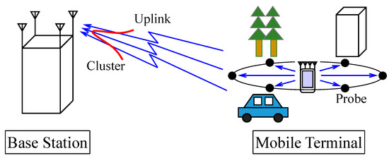
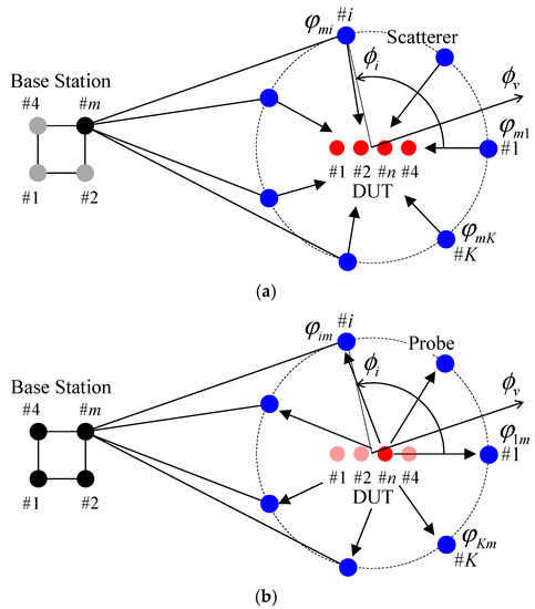
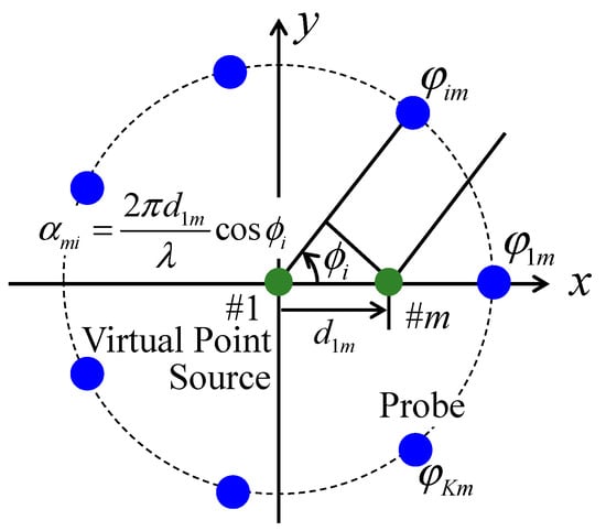
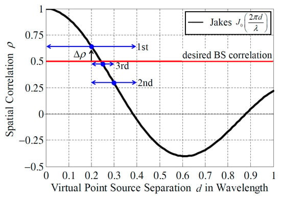
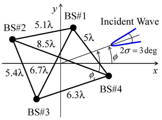
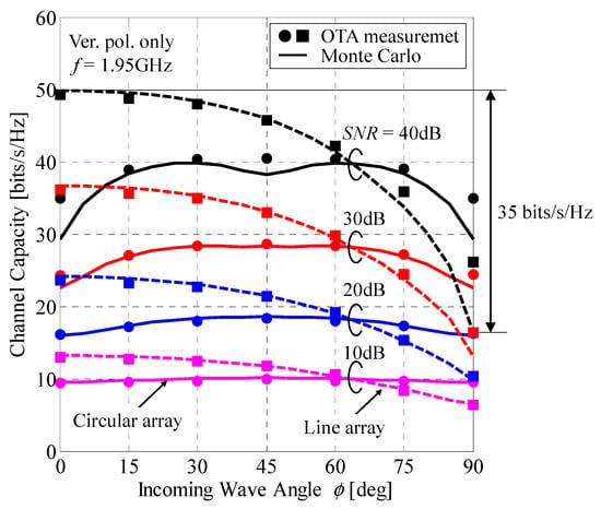
This paper presents a method of implementing a 4 × 4 correlation matrix for evaluating the uplink channel properties of multiple-input multiple-output (MIMO) antennas using an over-the-air measurement system. First, the implementation model used to determine the correlation coefficients between the signals received
[...] Read more.
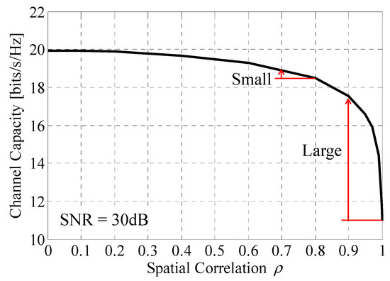
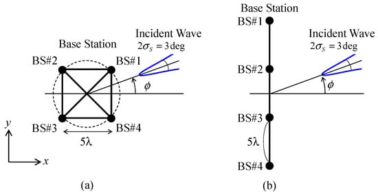
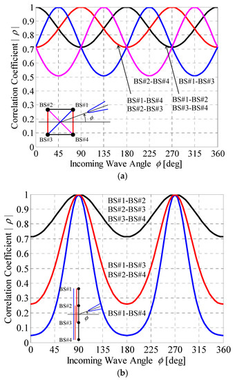
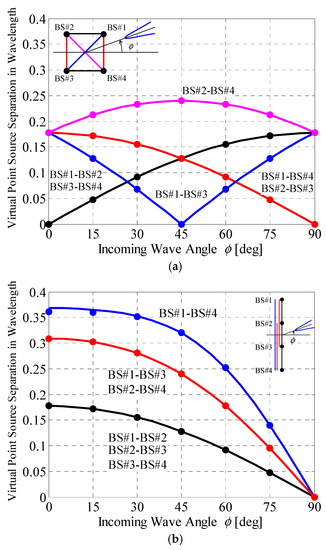
This paper presents a method of implementing a 4 × 4 correlation matrix for evaluating the uplink channel properties of multiple-input multiple-output (MIMO) antennas using an over-the-air measurement system. First, the implementation model used to determine the correlation coefficients between the signals received at the base station (BS) antennas via the uplink channel is described. Then, a methodology is introduced to achieve a 4 × 4 correlation matrix for a BS MIMO antenna based on Jakes’ model by setting the initial phases of the secondary wave sources in the two-dimensional channel model. The performance of the uplink channel for a four-element MIMO terminal array antenna is evaluated using a two-dimensional bidirectional fading emulator. The results show that the measured correlation coefficients between the signals received via the uplink channel at the BS antennas using the proposed method are in good agreement with the BS correlation characteristics calculated using Monte Carlo simulation and the theoretical formula, thereby confirming the effectiveness of the proposed method.
Full article
►▼
Show Figures
Open AccessArticle
Medium-Sized Highly Coupled Planar Arrays with Maximum Aperture Efficiency
by
Peyman Pourmohammadi, Vladimir Volski and Guy A. E. Vandenbosch
Cited by 14 | Viewed by 2097
Abstract
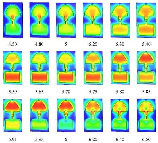
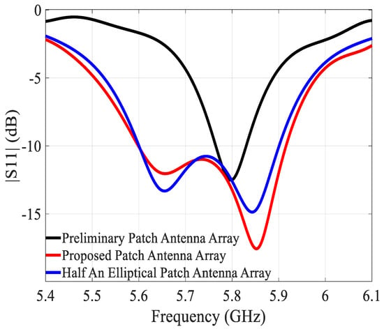
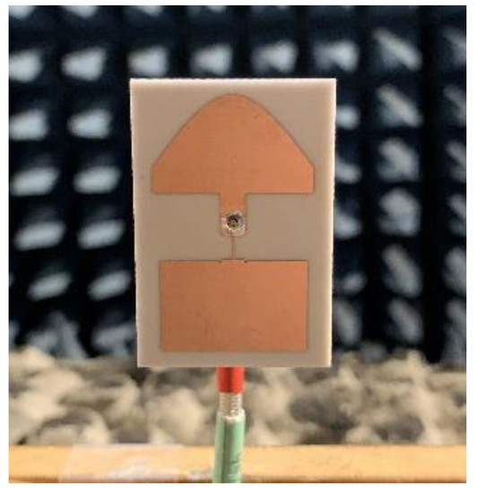
This paper presents a technique to design strongly coupled planar arrays with very high aperture efficiency. The key innovation is that, based on an irregular 2 × 1 array, very compact medium-sized arrays of size 2 × 2, 2 × 4, and 2
[...] Read more.
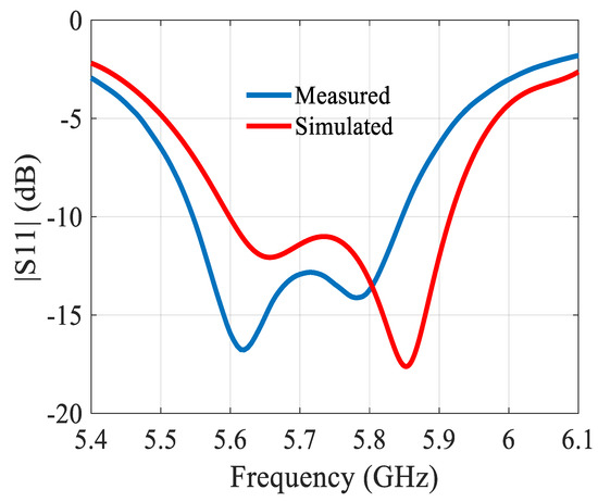
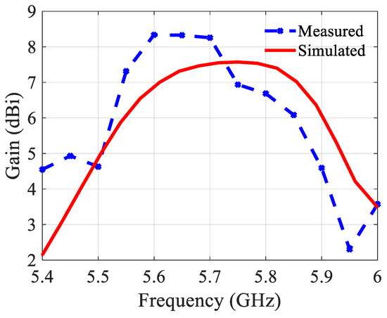
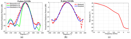
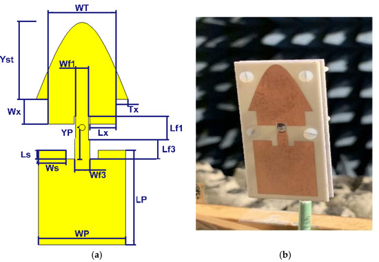
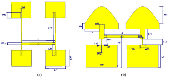
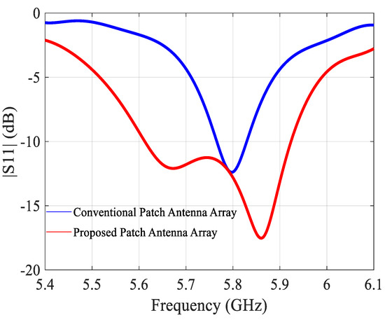
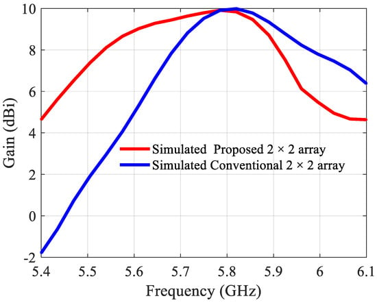
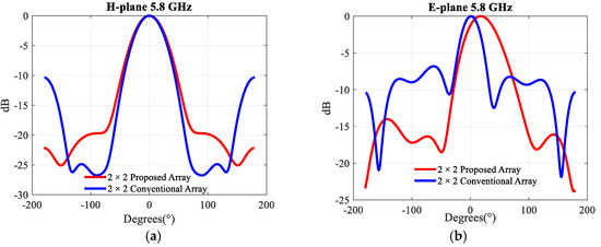
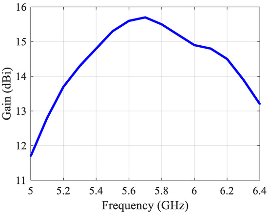
This paper presents a technique to design strongly coupled planar arrays with very high aperture efficiency. The key innovation is that, based on an irregular 2 × 1 array, very compact medium-sized arrays of size 2 × 2, 2 × 4, and 2 × 6 are constructed with very strong and constructive mutual coupling between the elements. In this way, a maximum aperture efficiency is reached for a given footprint of the array. The occupied space of the antenna in comparison with conventional linear patch arrays is studied. A prototype 2 × 4 array operating around 5.8 GHz is designed, fabricated, built, and measured. The results show a large bandwidth of 20% and a very high aperture efficiency of 100%, which is the largest found in the literature for similarly sized arrays. These results are important in view of the future Internet of Things, where small and medium-sized arrays are planned to be mounted on numerous devices where a very limited physical area is available.
Full article
►▼
Show Figures
Open AccessArticle
Alternative Formulation of Antenna Arrays for DF Systems Considering Active-Element Patterns and Scattering Matrices
by
Bernardo Fabiani, Eduardo Sakomura, Eduardo Silveira, Daniel Nascimento, Daniel Ferreira and Marcelo Pinho
Viewed by 1968
Abstract
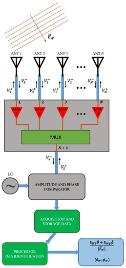
Direction finding (DF) systems are used to determine the direction-of-arrival (DoA) of electromagnetic waves, thus allowing for the tracking of RF sources. In this paper, we present an alternative formulation of antenna arrays for modeling DF systems. To improve the accuracy of the
[...] Read more.
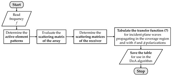
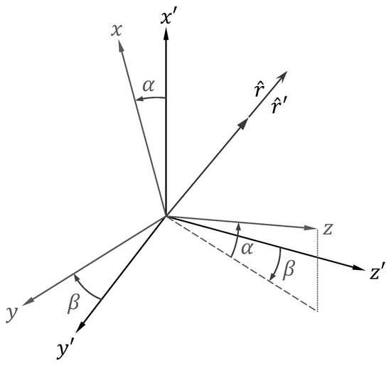
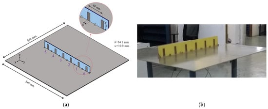
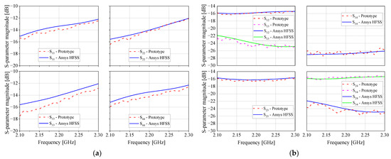
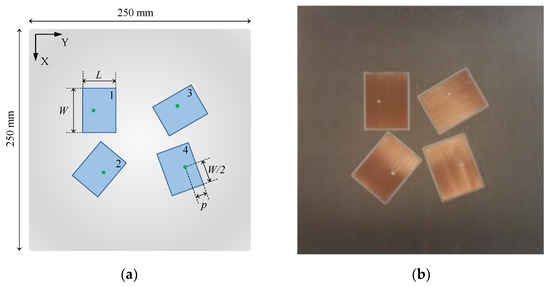
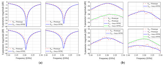
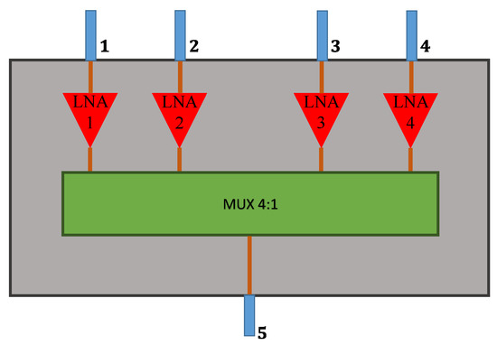
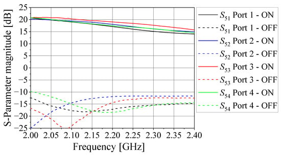
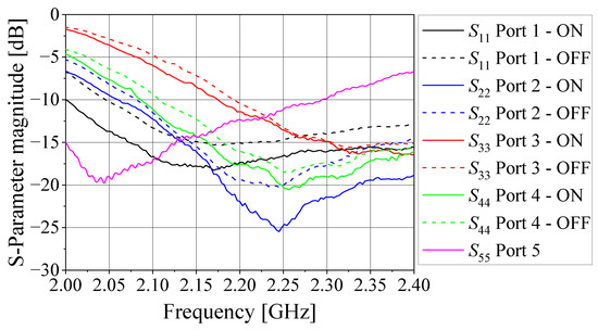
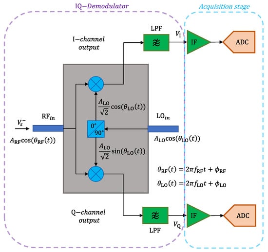
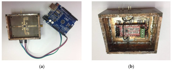
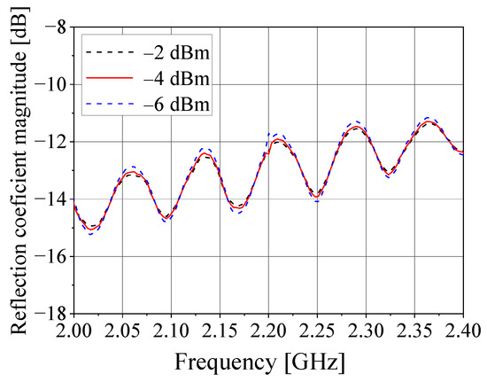
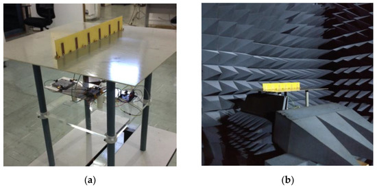
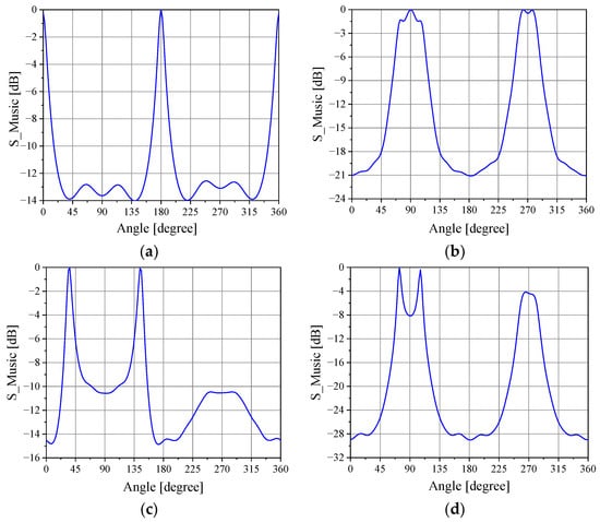
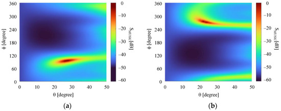
Direction finding (DF) systems are used to determine the direction-of-arrival (DoA) of electromagnetic waves, thus allowing for the tracking of RF sources. In this paper, we present an alternative formulation of antenna arrays for modeling DF systems. To improve the accuracy of the data provided by the DF systems, the effects of mutual coupling in the array, polarization of the received waves, and impedance mismatches in the RF front-end receiver are all taken into account in the steering vectors of the DoA algorithms. A closed-form expression, which uses scattering parameter data and active-element patterns, is derived to compute the receiver output voltages. Special attention is given to the analysis of wave polarization relative to the DF system orientation. Applying the formulation introduced here, a complete characterization of the received waves is accomplished without the need for system calibration techniques. The validation of the proposed model is carried out by measurements of a 2.2 GHz DF system running a MUSIC algorithm. Tests are performed with a linear array of printed monopoles and with a planar microstrip antenna array having polarization diversity. The experimental results show DoA estimation errors below 6° and correct classification of the polarization of incoming waves, confirming the good performance of the developed formulation.
Full article
►▼
Show Figures
Open AccessArticle
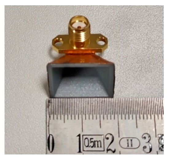
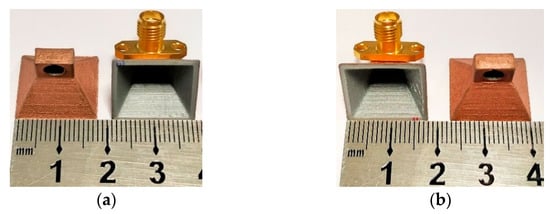
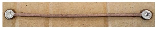
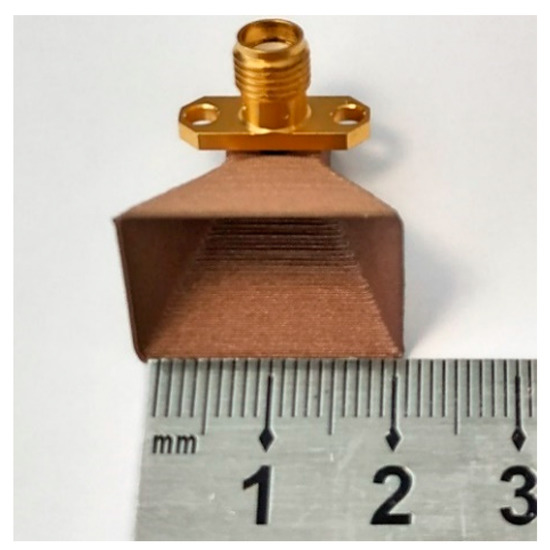
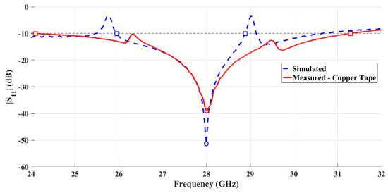
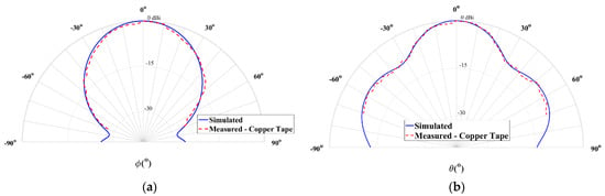
The Use of 3D Printing Technology for Manufacturing Metal Antennas in the 5G/IoT Context
by
Diogo Helena, Amélia Ramos, Tiago Varum and João N. Matos
Cited by 22 | Viewed by 4760
Abstract
With the rise of 5G, Internet of Things (IoT), and networks operating in the mmWave frequencies, a huge growth of connected sensors will be a reality, and high gain antennas will be desired to compensate for the propagation issues, and with low cost,
[...] Read more.
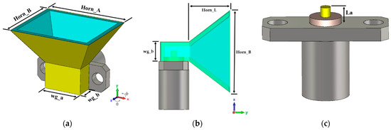
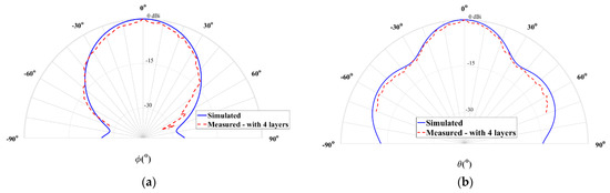
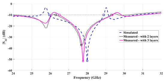
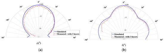
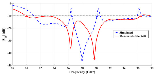
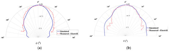
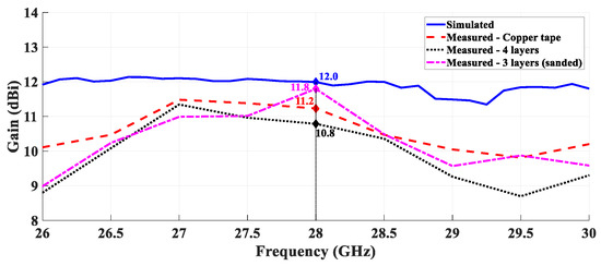
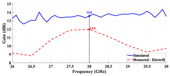
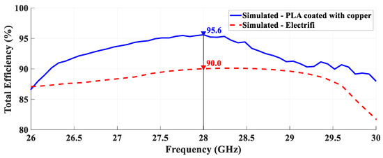
With the rise of 5G, Internet of Things (IoT), and networks operating in the mmWave frequencies, a huge growth of connected sensors will be a reality, and high gain antennas will be desired to compensate for the propagation issues, and with low cost, characteristics inherent to metallic radiating structures. 3D printing technology is a possible solution in this way, as it can print an object with high precision at a reduced cost. This paper presents different methods to fabricate typical metal antennas using 3D printing technology. These techniques were applied as an example to pyramidal horn antennas designed for a central frequency of 28 GHz. Two techniques were used to metallize a structure that was printed with polylactic acid (PLA), one with copper tape and other with a conductive spray-paint. A third method consists of printing an antenna completely using a conductive filament. All prototypes combine good results with low production cost. The antenna printed with the conductive filament achieved a better gain than the other structures and showed a larger bandwidth. The analysis recognizes the vast potential of these 3D-printed structures for IoT applications, as an alternative to producing conventional commercial antennas.
Full article
►▼
Show Figures


