Application of Computational Fluid Dynamics in Mechanical Engineering
Share This Topical Collection
Editor
 Prof. Dr. Hoyas Calvo Sergio
Prof. Dr. Hoyas Calvo Sergio
E-Mail
Website
Guest Editor
Aerospace Engineering, Universitat Politècnica de València, 46022 Valencia, Spain
Interests: computational fluid dynamics; wall turbulence
Topical Collection Information
Dear Colleagues,
Turbulence is probably the one open problem in physics with the most applications in daily life. Even although the equations controlling fluid flow, the Navier–Stokes equations, have been known for more than 150 years, relatively little is known about the physics behind turbulent flows. The bad news is that turbulence is persistent in mechanical engineering. Almost all flows of interest are turbulent. The good news is that several excellent models have been developed in the last 50 years that allow us to obtain excellent results. A great variety of RANS methods can compute mean values of very complex flows. Moreover, with the continuous development of computational power, LES methods can be used now to increase our knowledge of extremely complex flows of interest in mechanical engineering. The list of flows where CFD is applied is longer every year: rocket engineering, aerodynamics, reciprocating engines, wind energy, etc.
This Special Issue will reflect the works in these fields, focusing on applications more than theoretical methods. Any work showing new insights into the fascinating world of CFD is warmly welcome.
Prof. Dr. Hoyas Calvo Sergio
Guest Editor
Manuscript Submission Information
Manuscripts should be submitted online at www.mdpi.com by registering and logging in to this website. Once you are registered, click here to go to the submission form. Manuscripts can be submitted until the deadline. All submissions that pass pre-check are peer-reviewed. Accepted papers will be published continuously in the journal (as soon as accepted) and will be listed together on the collection website. Research articles, review articles as well as short communications are invited. For planned papers, a title and short abstract (about 100 words) can be sent to the Editorial Office for announcement on this website.
Submitted manuscripts should not have been published previously, nor be under consideration for publication elsewhere (except conference proceedings papers). All manuscripts are thoroughly refereed through a single-blind peer-review process. A guide for authors and other relevant information for submission of manuscripts is available on the Instructions for Authors page. Applied Sciences is an international peer-reviewed open access semimonthly journal published by MDPI.
Please visit the Instructions for Authors page before submitting a manuscript.
The Article Processing Charge (APC) for publication in this open access journal is 2400 CHF (Swiss Francs).
Submitted papers should be well formatted and use good English. Authors may use MDPI's
English editing service prior to publication or during author revisions.
Keywords
- CFD
- RANS
- LES
- reciprocating engines
- mechanical engineering
- aerodynamics
- wind energy
- urban flows
- sprays
- turbine
- compressible flows
- industrial flows
- trains
- rockets
- heat transfer
- medical flows
- aerospace
- thermal flows
Published Papers (25 papers)
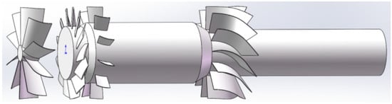
Open AccessArticle
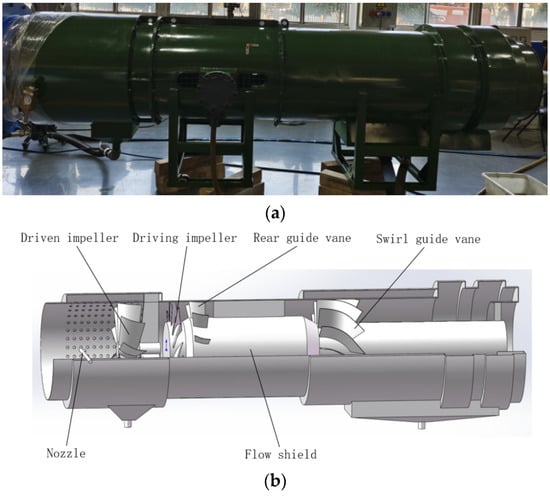
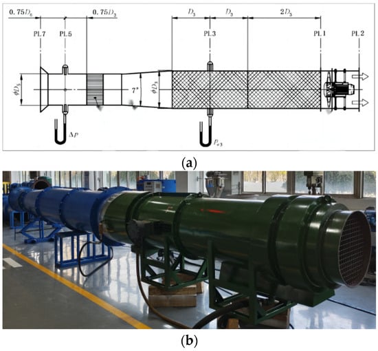
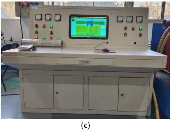
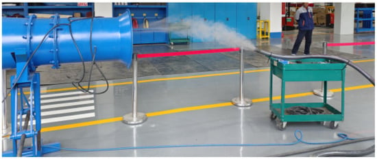
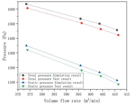
Study on the Influence of Dust Removal Fan Structure Parameters on Dust Removal Performance
by
Jinchen Zhao, Guijun Gao and Xinqi Gao
Viewed by 312
Abstract
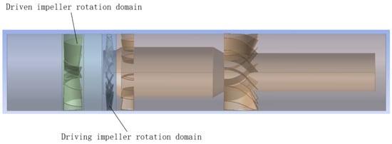
In order to study the influence of various parts of the structure of a wet dust removal fan for mining (including the number of driving impeller blades, the airfoil of the driving impeller blades, the number of driven impeller blades, the rear guide
[...] Read more.
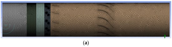
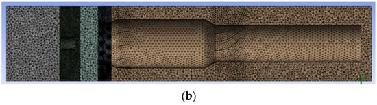
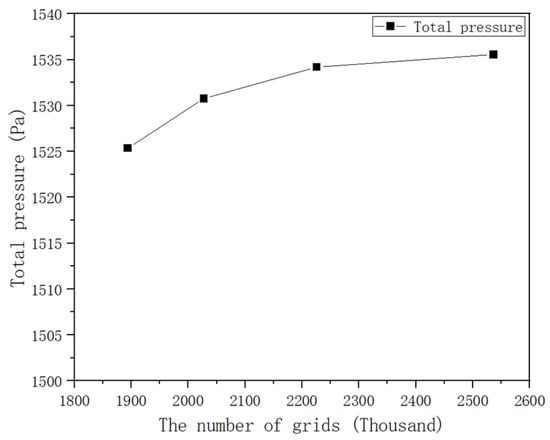
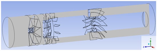
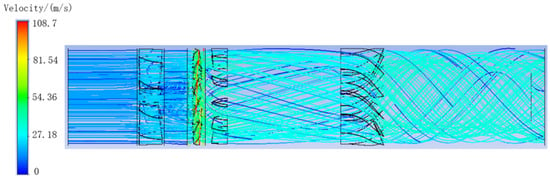
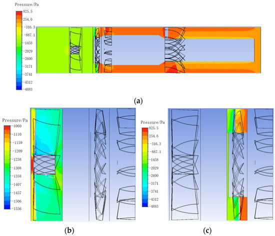
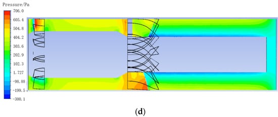
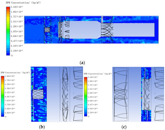
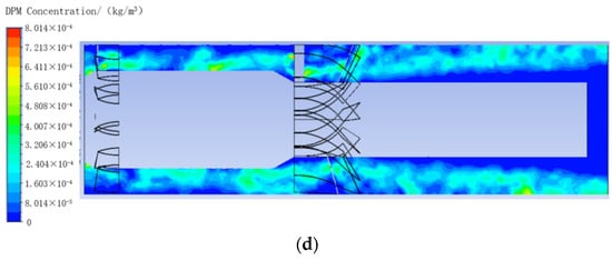
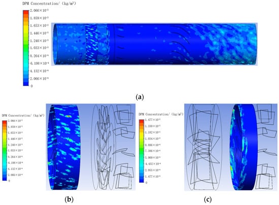
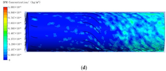
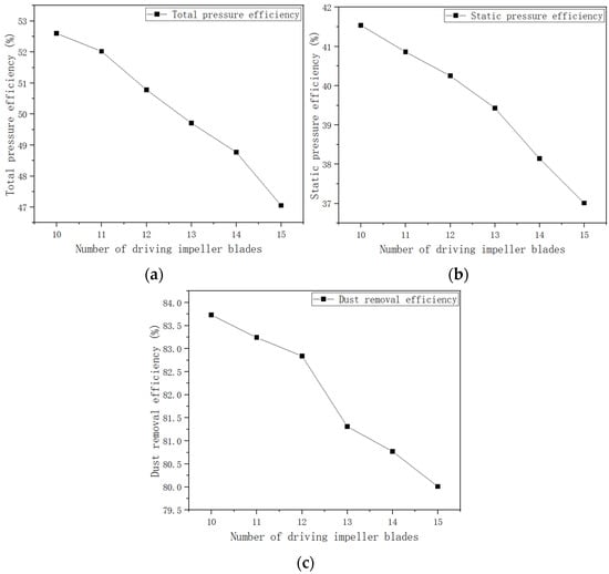
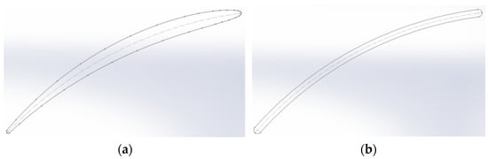
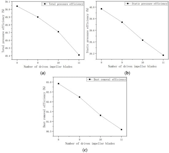
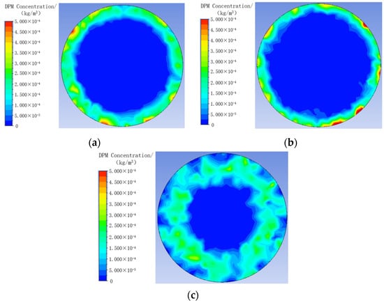
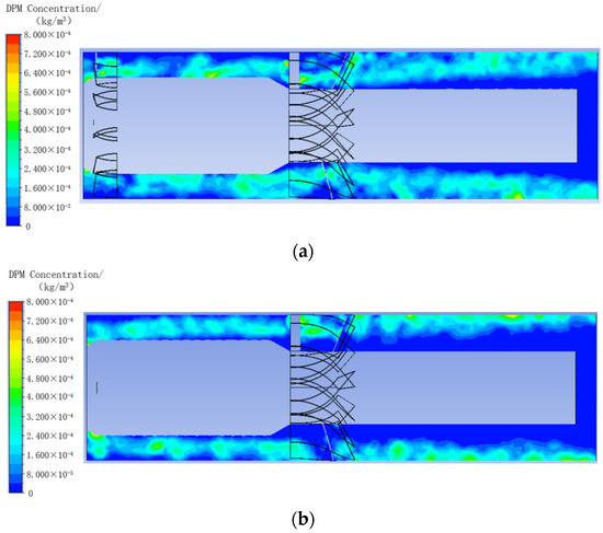
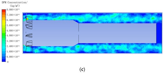
In order to study the influence of various parts of the structure of a wet dust removal fan for mining (including the number of driving impeller blades, the airfoil of the driving impeller blades, the number of driven impeller blades, the rear guide vane, the swirl guide vane, and the length of the outlet section) on dust removal performance, a wet dust removal fan for mining was modeled according to different structural parameters. The internal flow field and dust removal of the fan were then numerically simulated using the Computational Fluid Dynamics (CFD) method. The results show that after the airflow passes through the swirl guide vane of the dust removal fan, there is an obvious swirl flow in the exit section of the dust removal fan. Under the action of centrifugal force, a large amount of dust is collected on the side wall of the exit section. With the increase in the number of driving impeller blades, the total pressure efficiency, static pressure efficiency, and dust removal efficiency of the dust removal fan decrease. When the driving impeller blade adopts the C-4 airfoil, the total pressure efficiency and static pressure efficiency of the dust removal fan are higher but the dust removal efficiency is lower than that of the same thickness circular plate airfoil. With the increase in the number of driven impeller blades, the power of the driving impeller shaft of the dust removal fan gradually increases; the total pressure and static pressure values first increase and then decrease; and the driven impeller speed, total pressure efficiency, static pressure efficiency, and dust removal efficiency gradually decrease. Adding the rear guide vane structure can improve the total pressure efficiency and static pressure efficiency of the dust removal fan but will reduce the dust removal efficiency of the dust removal fan. The increase in the swirl guide vane structure will reduce the total pressure efficiency and static pressure efficiency of the dust removal fan but the dust removal efficiency will be significantly improved. The extension of the outlet section of the dust removal fan will reduce the total pressure efficiency and static pressure efficiency of the dust removal fan, but the dust removal efficiency will increase. In this paper, by changing the structural parameters of the dust removal fan and establishing different models for numerical simulation and analysis, the influence law of the structural parameters of the dust removal fan on the dust removal performance is obtained, providing a way to improve the performance of the dust removal fan.
Full article
►▼
Show Figures
Open AccessArticle
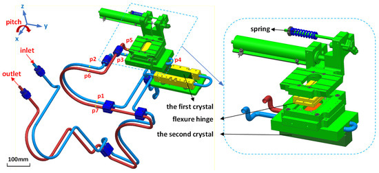
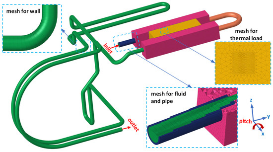
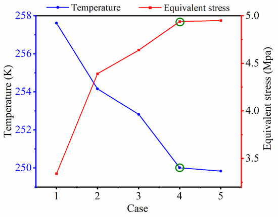
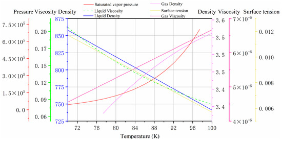
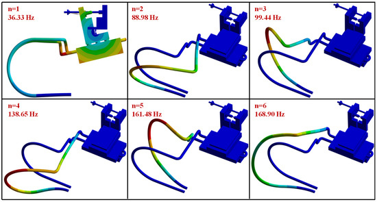
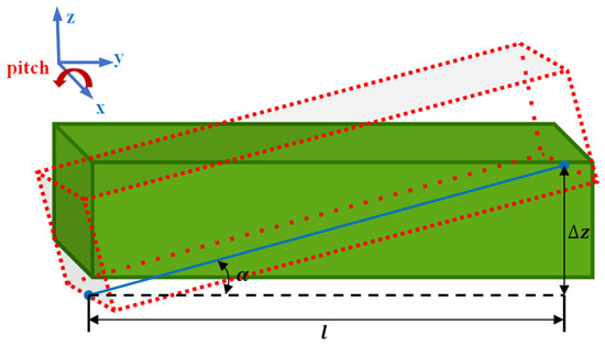
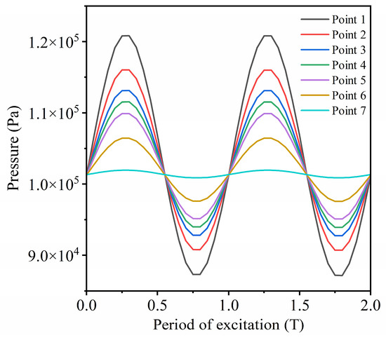
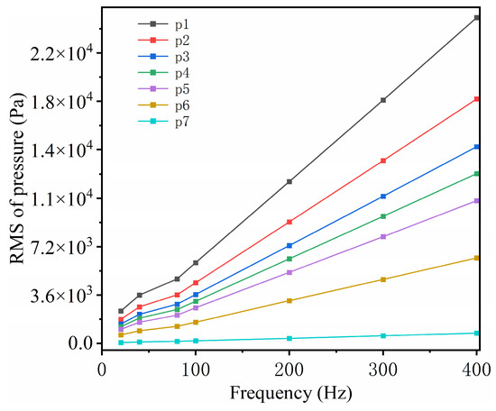
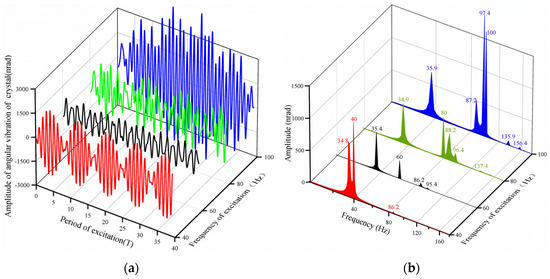
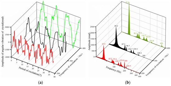
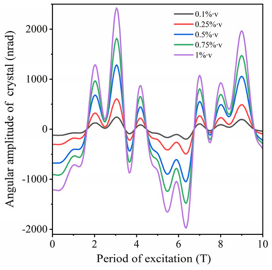
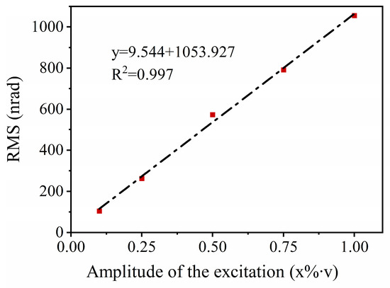
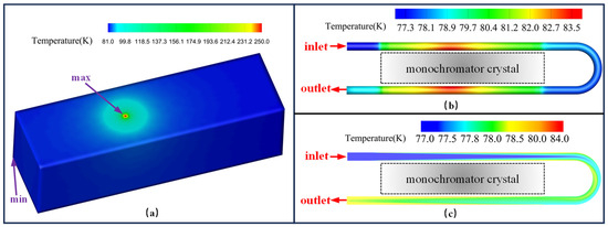
Research on the Mechanism of Flow-Induced Vibration in the Cooling System of a Double Crystal Monochromator
by
Ao Li, Xuepeng Gong, Yang Bai, Qipeng Lu, Shengchi Li, Wenbo Zhang and Kewei Chai
Viewed by 422
Abstract
To investigate the mechanism of flow-induced vibrations in the cooling system of a double crystal monochromator (DCM), this paper utilizes a multi-physics numerical simulation approach, employing ANSYS and FLUENT platforms to simulate the flow state of liquid nitrogen in the cooling system and
[...] Read more.
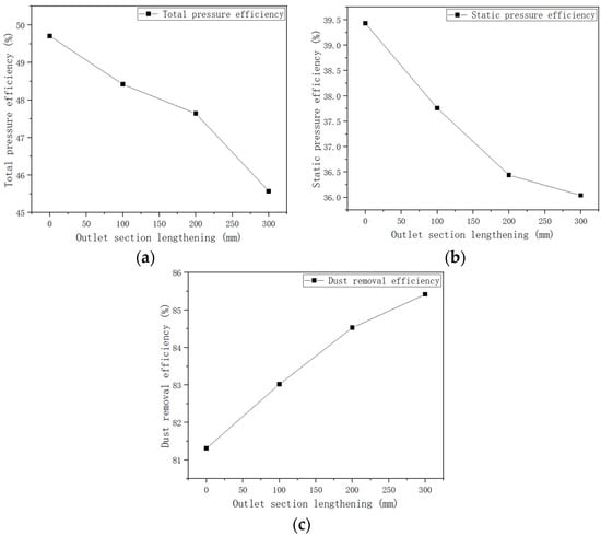
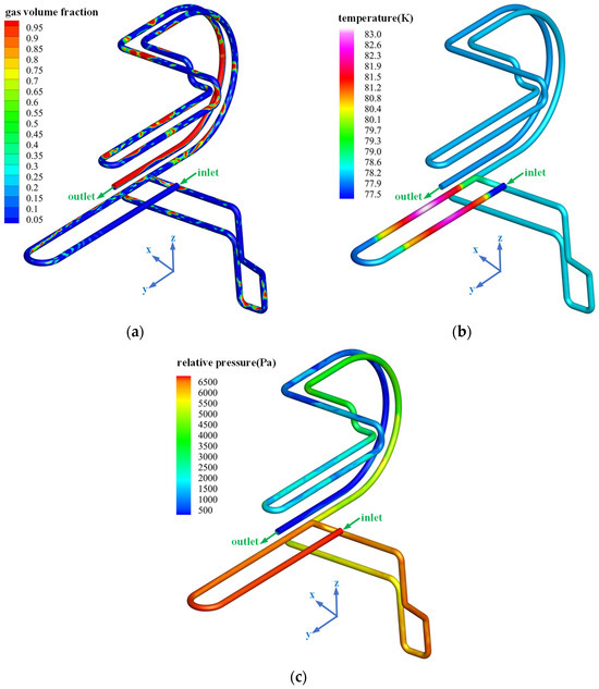
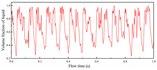
To investigate the mechanism of flow-induced vibrations in the cooling system of a double crystal monochromator (DCM), this paper utilizes a multi-physics numerical simulation approach, employing ANSYS and FLUENT platforms to simulate the flow state of liquid nitrogen in the cooling system and explore the amplitude response of the DCM. Initially, simulations were conducted to examine the flow state of liquid nitrogen with varying frequency and amplitude pulsations. Subsequently, modal analysis was employed to investigate the amplitude response of the DCM in the pitch direction vibrations under pulsating excitation. Finally, this research investigated the influence of high heat load-induced liquid nitrogen boiling on a DCM. The results indicate that pipe resistance is the fundamental cause of vibration induced by pulsating excitation. Low-frequency excitation enhances the amplification factor of DCM vibration. In contrast, due to the rapid conversion of fluid kinetic energy to pressure potential energy, high-frequency excitation increases the pulsation amplitude in the pipe. Additionally, there is a linear relationship between the amplitude of liquid nitrogen velocity fluctuations and the response amplitude of a DCM. The slug flow formed after liquid nitrogen boiling generates low-frequency pulse signals, and intermittent fluid impacts cause significant vibrations in the DCM. These research findings provide a reference for the analysis and design of ultra-high-stability DCM cooling systems.
Full article
►▼
Show Figures
Open AccessArticle
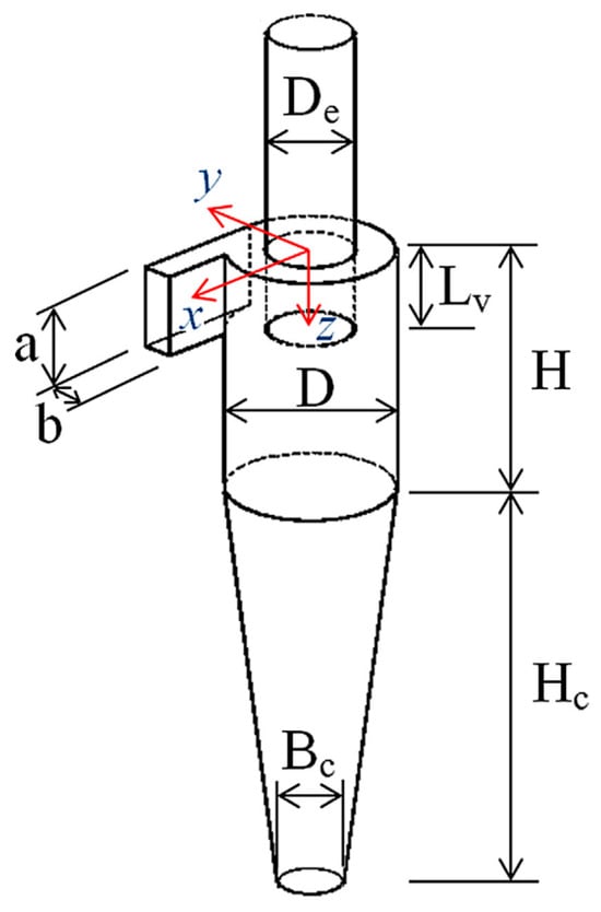
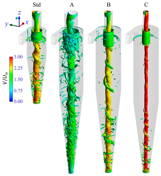
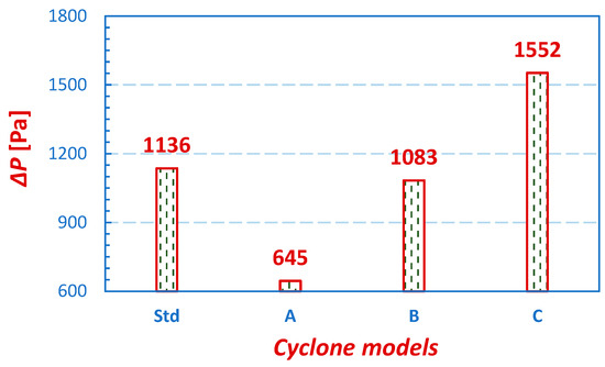
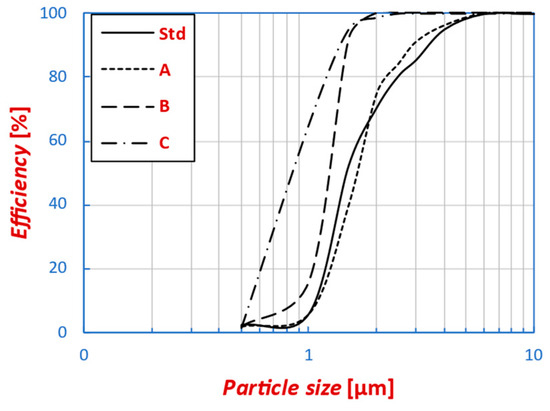
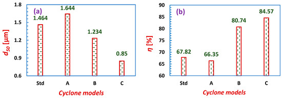
Multi-Objective Optimization of Cyclone Separators Based on Geometrical Parameters for Performance Enhancement
by
Satyanand Pandey, Marek Wasilewski, Arkadeb Mukhopadhyay, Om Prakash, Asim Ahmad and Lakhbir Singh Brar
Viewed by 519
Abstract
The present study focuses on performing multi-objective optimization of the cyclone separator geometry to lower the pressure losses and enhance the collection efficiency. For this, six geometrical entities, such as the main body diameter of the cyclone, the vortex finder diameter and its
[...] Read more.
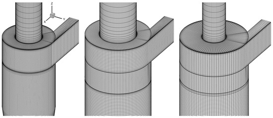
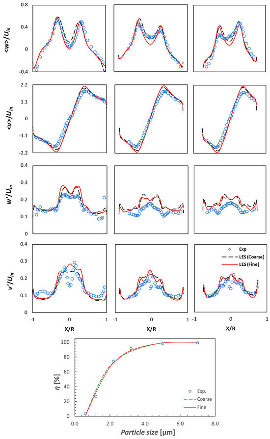
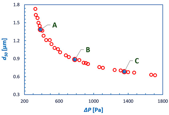
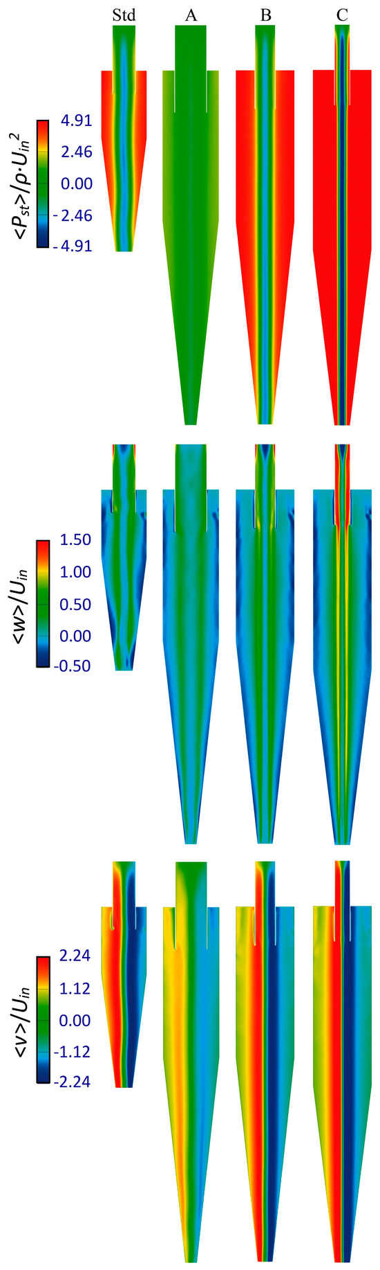
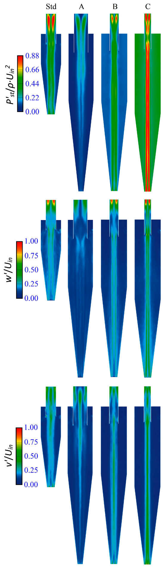
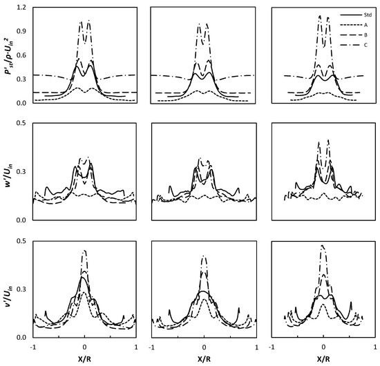
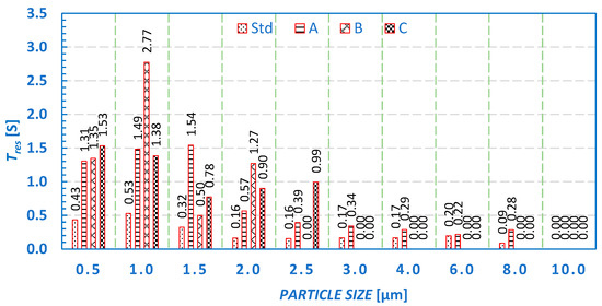
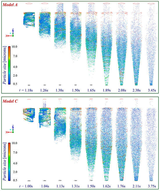
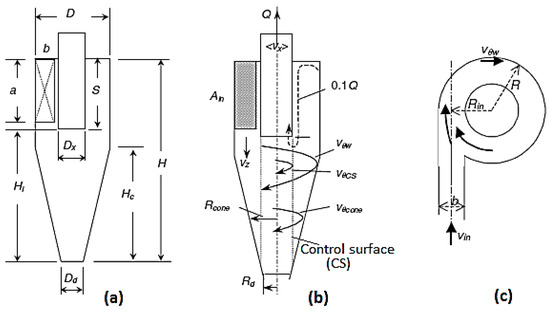
The present study focuses on performing multi-objective optimization of the cyclone separator geometry to lower the pressure losses and enhance the collection efficiency. For this, six geometrical entities, such as the main body diameter of the cyclone, the vortex finder diameter and its insertion length, the cone tip diameter, and the height of the cylindrical and conical segment, have been accounted for optimization, and the Muschelknautz method of modeling has been used as an objective function for genetic algorithms. To date, this is one of the most popular mathematical models that accurately predicts the cyclone performance, such as the pressure drop and cut-off particle size. Three cases have been selected from the Pareto fronts, and the cyclone performance is calculated using advanced closure large-eddy simulation—the results are then compared to the baseline model to evaluate the relative improvement. It has been observed that in one of the models, with merely a 2% reduction in the collection efficiency and an increase of 12% in the cut-off particle size, more than a 43% reduction in pressure drop value was obtained (an energy-efficient model). In another model, a nearly 25% increment in the collection efficiency and a reduction of 42% in the cut-off particle size with a nearly 36% increase in pressure drop value were observed (a high-efficiency model).
Full article
►▼
Show Figures
Open AccessArticle
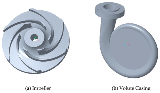
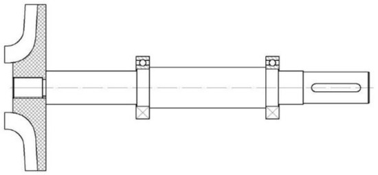
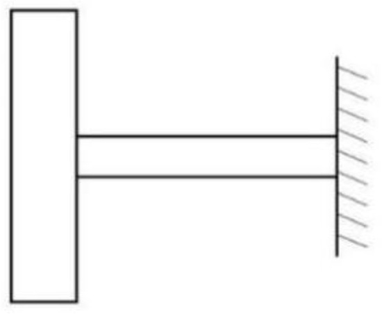
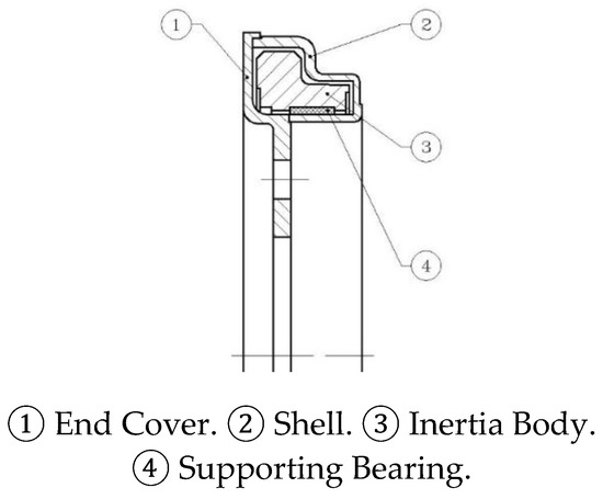
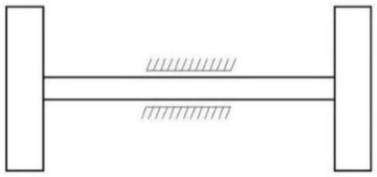
Research on Vibration Reduction in the Transmission System of Plastic Centrifugal Pump
by
Lili Zhang, Lingfeng Tang and Qingzhao Wen
Viewed by 1484
Abstract
The inherent weakness in the deformation resistance of plastic centrifugal pumps makes them prone to vibrations. This study explores the impact of flow components on the vibrations of such pumps. Utilizing the given parameters, the primary structural parameters of the plastic centrifugal pump
[...] Read more.
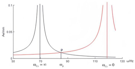
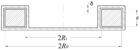
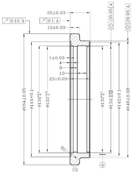
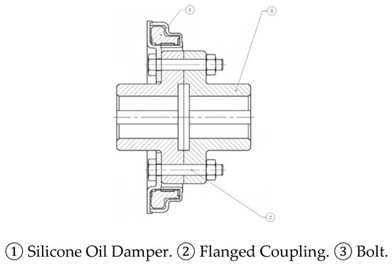
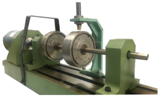
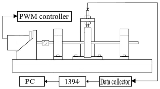
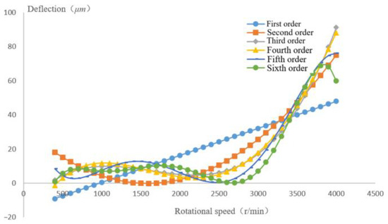
The inherent weakness in the deformation resistance of plastic centrifugal pumps makes them prone to vibrations. This study explores the impact of flow components on the vibrations of such pumps. Utilizing the given parameters, the primary structural parameters of the plastic centrifugal pump were calculated. The study focused on the torsional vibrations within the pump shaft transmission system, employing a silicone oil damper for vibration mitigation. A dual-mass forced torsion vibration model was developed for the pump shaft transmission system with the added damper. The optimal damping coefficient for this damper was determined, and its structural design was completed, including the creation of three-dimensional models and two-dimensional part drawings. Utilizing a ZT-3 type rotor test bench, a mathematical model correlating centrifugal pump speed with deflection was developed, and the effectiveness of various polynomials was assessed. The analysis showed that the optimal damping value for the silicone oil damper is 0.22. Compared to the system without the damper, the vibration frequency reduced by 10.45%, and the vibration amplitude decreased by 49.29%, demonstrating excellent vibration reduction effectiveness.
Full article
►▼
Show Figures
Open AccessArticle
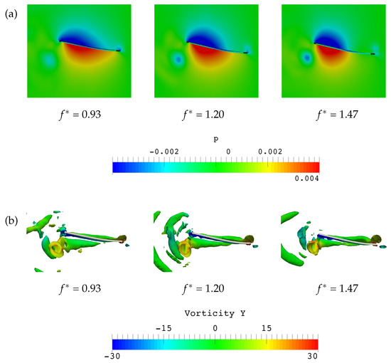
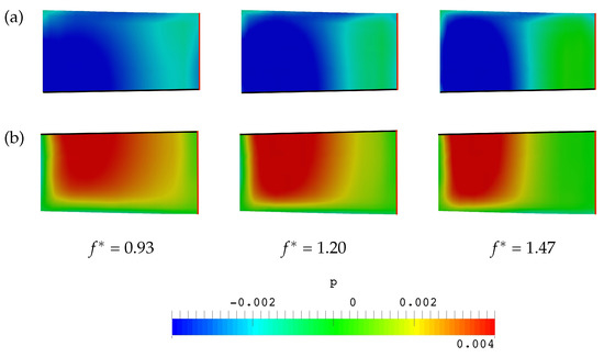
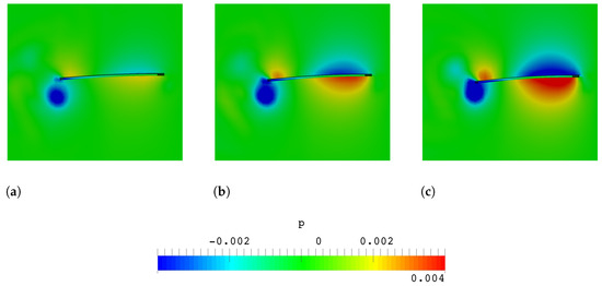
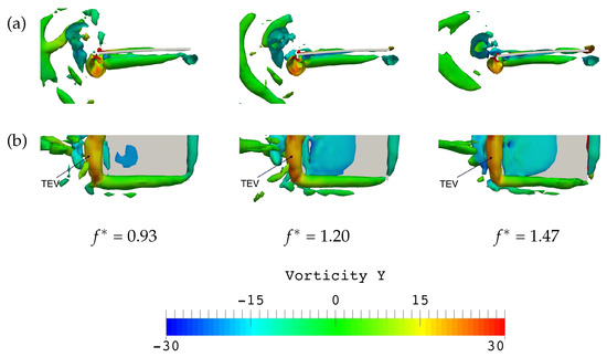
Three-Dimensional Hydrodynamic Analysis of a Flexible Caudal Fin
by
May Hlaing Win Khin and Shinnosuke Obi
Viewed by 1340
Abstract
A 3D fluid–structure coupled simulation of a square flexible flapper, the basic model of a caudal fin, is performed to visualize the flow field around the caudal fin. A plate immersed in a water tank is driven to oscillate vertically by its leading
[...] Read more.
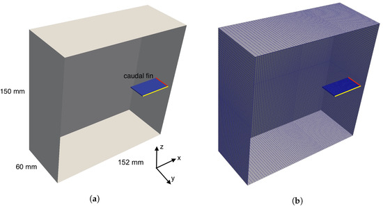
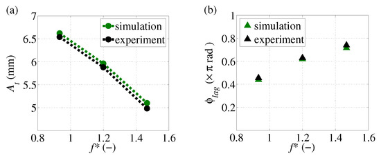
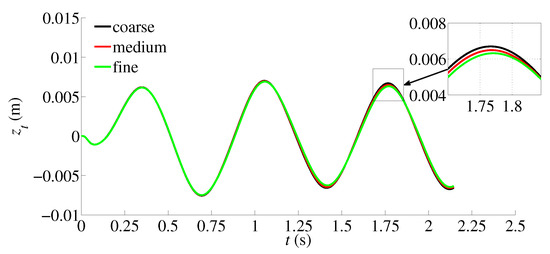
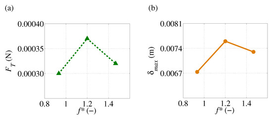
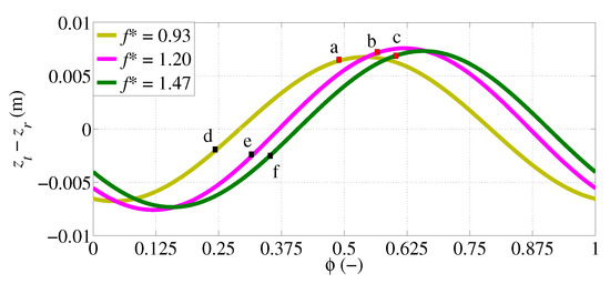
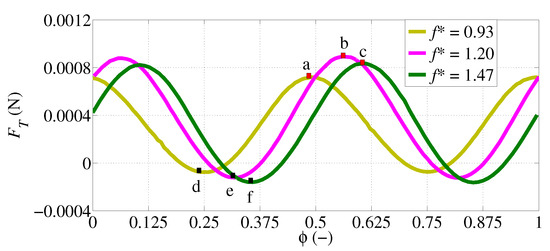
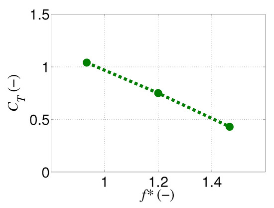
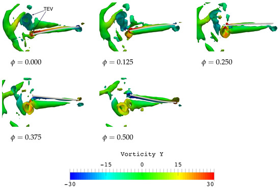
A 3D fluid–structure coupled simulation of a square flexible flapper, the basic model of a caudal fin, is performed to visualize the flow field around the caudal fin. A plate immersed in a water tank is driven to oscillate vertically by its leading edge. A quantitative analysis of the thrust generated by the plate, which is difficult to explore experimentally, is performed over a range of non-dimensional flapping frequencies 0.93
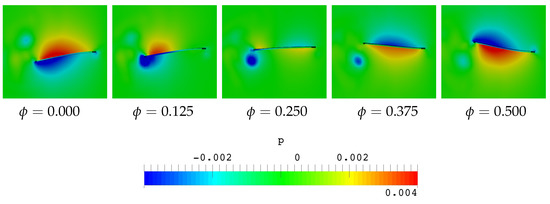
1.47 to explore the mechanism of thrust generation in more detail. Comparisons are made between three different flapping frequencies around the structural resonance. Numerical results at different flapping frequencies provide a reasonable estimate of the trailing edge amplitude and phase lag of the motion of the plate’s leading and trailing edges. The pressure distribution and deformation of the plate are analyzed to estimate the time evolution of the maximum and minimum thrust generation during the flapping period. Variations in pressure distribution on the plate surface are mainly due to the displacement of the trailing edge relative to the leading edge. Thrust is mainly provided by the pressure difference at the trailing edge. The maximum thrust was found to correspond to the maximum relative deformation of the trailing edge. The optimum frequency
= 1.2 corresponding to the maximum thrust generation does not coincide with the structural resonance frequency, but remains at a frequency slightly higher than the resonance. These results indicate that the relative deformation of the plate plays an important role in the estimation of the flow field and the associated thrust generation. The numerical results may provide new guidelines for the design of robotic underwater vehicles.
Full article
►▼
Show Figures
Open AccessArticle
Hybrid VOF–Lagrangian CFD Modeling of Droplet Aerobreakup
by
Viola Rossano and Giuliano De Stefano
Cited by 8 | Viewed by 1849
Abstract
A hybrid VOF–Lagrangian method for simulating the aerodynamic breakup of liquid droplets induced by a traveling shock wave is proposed and tested. The droplet deformation and fragmentation, together with the subsequent mist development, are predicted by using a fully three-dimensional computational fluid dynamics
[...] Read more.
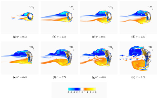
A hybrid VOF–Lagrangian method for simulating the aerodynamic breakup of liquid droplets induced by a traveling shock wave is proposed and tested. The droplet deformation and fragmentation, together with the subsequent mist development, are predicted by using a fully three-dimensional computational fluid dynamics model following the unsteady Reynolds-averaged Navier–Stokes approach. The main characteristics of the aerobreakup process under the shear-induced entrainment regime are effectively reproduced by employing the scale-adaptive simulation method for unsteady turbulent flows. The hybrid two-phase method combines the volume-of-fluid technique for tracking the transient gas–liquid interface on the finite volume grid and the discrete phase model for following the dynamics of the smallest liquid fragments. The proposed computational approach for fluids engineering applications is demonstrated by making a comparison with reference experiments and high-fidelity numerical simulations, achieving acceptably accurate results without being computationally expensive.
Full article
►▼
Show Figures
Open AccessArticle
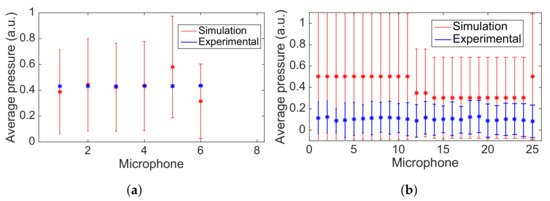
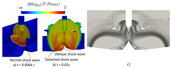
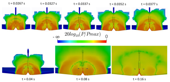
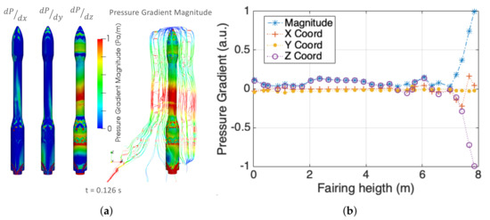
URANS Analysis of a Launch Vehicle Aero-Acoustic Environment
by
Mara S. Escartí-Guillem, Luis M. García-Raffi and Sergio Hoyas
Cited by 6 | Viewed by 2879
Abstract
Predicting and mitigating acoustic levels become critical because of the harsh acoustic environment during space vehicle lift-off. This paper aimed to study the aero-acoustic environment during a rocket lift-off. The sound propagation within a launch event was studied using dedicated computational fluid dynamics
[...] Read more.
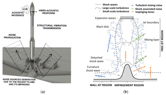
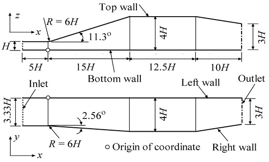
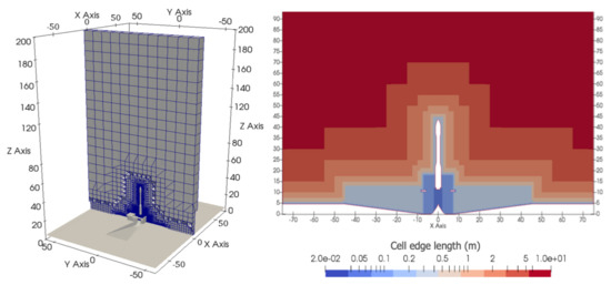
Predicting and mitigating acoustic levels become critical because of the harsh acoustic environment during space vehicle lift-off. This paper aimed to study the aero-acoustic environment during a rocket lift-off. The sound propagation within a launch event was studied using dedicated computational fluid dynamics (CFD). The resolution of all the phenomena that occur is unfeasible. We discuss the turbulence simplification and propose a feasible simulation through an unsteady Reynolds-averaged Navier–Stokes (URANS) model. The results were validated with experimental data showing a good correlation near the fairing surface and an improvable accuracy in the far field. To assess noise generation, the main shock waves were identified, and the evolution of the generated sound pressure was assessed. Moreover, vertical directivity was revealed by data analysis of the pressure field surrounding the fairing.
Full article
►▼
Show Figures
Open AccessArticle
An Elliptic Blending Turbulence Model-Based Scale-Adaptive Simulation Model Applied to Fluid Flows Separated from Curved Surfaces
by
Xianglong Yang and Lei Yang
Cited by 3 | Viewed by 2322
Abstract
On the basis of a previously developed elliptic blending turbulence model (SST–
k–
ω–
φ–
α model), a scale-adaptive simulation (SAS) model is developed by following Menter and Egorov’s SAS concept. An SAS source term, which is related to the
[...] Read more.
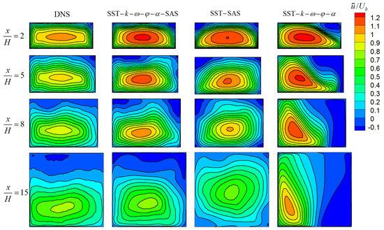
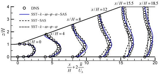
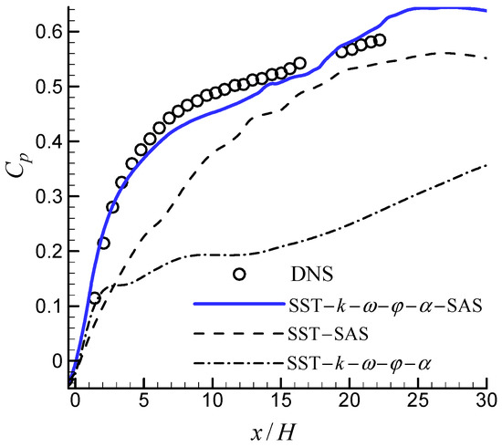
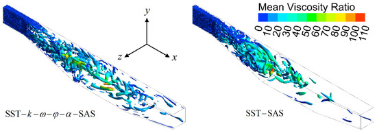
On the basis of a previously developed elliptic blending turbulence model (SST–
k–
ω–
φ–
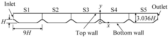
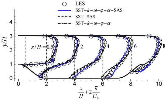
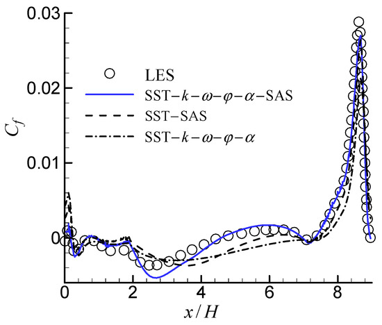
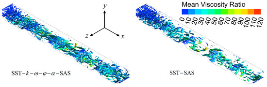
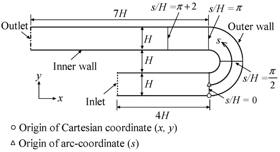
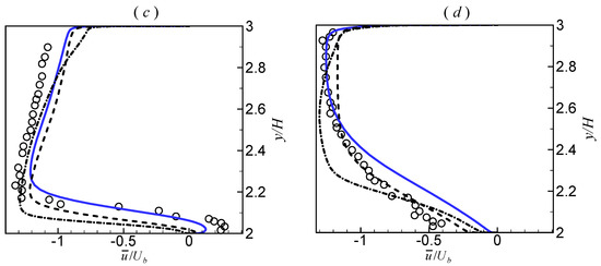
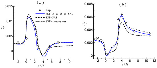
α model), a scale-adaptive simulation (SAS) model is developed by following Menter and Egorov’s SAS concept. An SAS source term, which is related to the ratio of the modeled turbulence scale to the von Kármán length scale, is introduced into the corresponding length-scale determining equation. The major motivation of this study is that the conventional unsteady Reynolds-averaged Navier–Stokes (URANS) models provide only large-scale unsteadiness. The introduction of the SAS term allows the proposed SAS model to dynamically adjust to resolved structures in a URANS framework because this term is sensitive to resolved fluctuations. The predictive capabilities of the proposed SAS model are demonstrated by computing the complex flow configurations in three cases with flow separation from curved surfaces, namely, three-dimensional (3D) diffuser flow, two-dimensional (2D) periodic hills flow, and 2D U-turn duct flow. For comparison, the results predicted by the SST–
k–
ω–
φ–
α model and the Menter and Egorov’s SAS model (SST–SAS) are provided. The results are also compared with the relevant experimental, direct numerical simulation, and large eddy simulation data. The results show that the SST–
k–
ω–
φ–
α model cannot capture the critical features for all three flows, and that the SST–SAS model is able to predict the results reasonably well. The proposed SAS model is capable of resolving more portions of the turbulence structures, and it yields the best results in all the cases.
Full article
►▼
Show Figures
Open AccessArticle
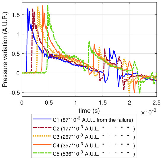
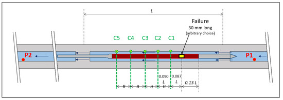
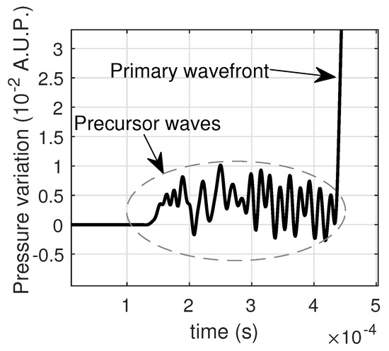
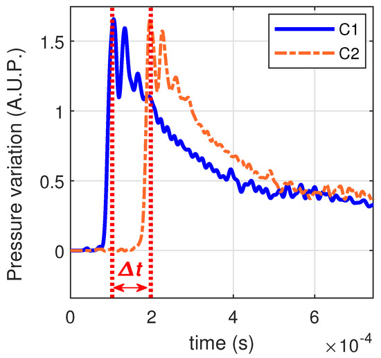
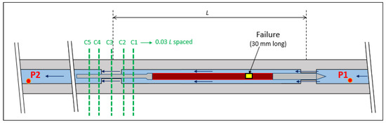
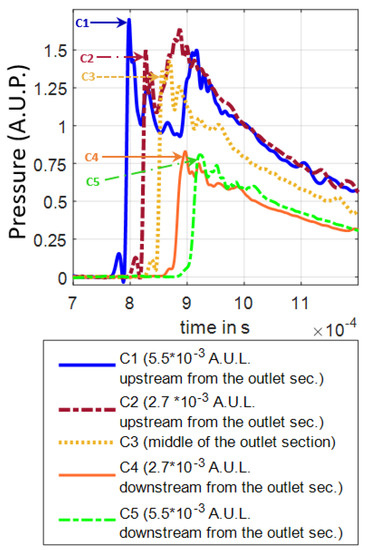
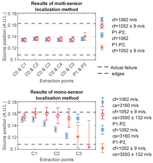
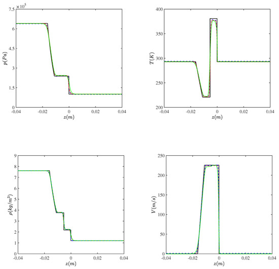
Numerical Study of Coupled Fluid and Solid Wave Propagation Related to the Cladding Failure of a Nuclear Fuel Rod
by
Tristan Julien, Vincent Faucher, Laurent Pantera, Guillaume Ricciardi and Emmanuelle Sarrouy
Cited by 1 | Viewed by 1480
Abstract
Fuel rod cladding failure in a nuclear reactor produces different phenomena related to vibrations and fluid–structure interaction. The most significant aspect of those phenomena is the creation of a pressure wave at the failure position and its propagation in the coolant fluid flowing
[...] Read more.
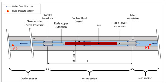
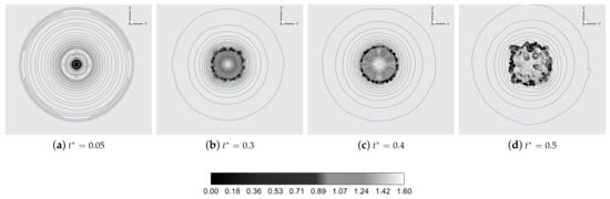
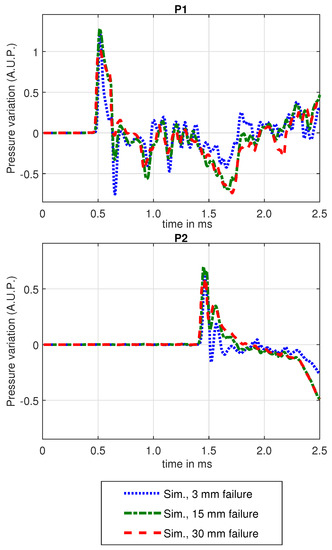
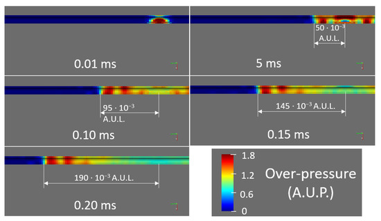
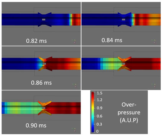
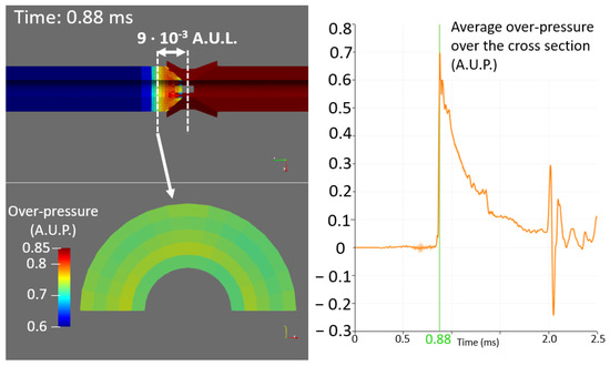
Fuel rod cladding failure in a nuclear reactor produces different phenomena related to vibrations and fluid–structure interaction. The most significant aspect of those phenomena is the creation of a pressure wave at the failure position and its propagation in the coolant fluid flowing around the fuel rod. An accurate understanding of the propagation of the pressure wave around the fuel rod can help us design a method to detect a failure, determine its position, and estimate some of its characteristics with a single and simple sensor, such as a pressure sensor or a piezoelectric acoustic sensor, that can be mounted relatively far from the failure. Such a method can be useful for the monitoring of nuclear fuel rods, where instrumentation possibilities are restricted (because of neutron flux, radiation, high temperature, and available space) as well as for any kind of application involving annular ducts and limited instrumentation possibilities. The current paper is related to the specific application of nuclear fuel rod monitoring. It deals with preliminary numerical simulations that are necessary to know the evolution of a fluid pressure profile along the system containing the rod. They are carried out by finite element methods, using the EUROPLEXUS code. They provide the necessary information about the propagation of pressure waves around the rod to design measurement and signal processing methods as well as properly interpret experimental results from tests in industrial reactors, research reactors, or experimental mock-ups. They also provide some information that could not be experimentally obtained because of the constraints in a nuclear environment. Despite the specific application we show in this article, similar calculation methods, theoretical observations, and results interpretations can be easily adapted to the other mentioned applications.
Full article
►▼
Show Figures
Open AccessArticle
Computational Evaluation of Shock Wave Interaction with a Liquid Droplet
by
Viola Rossano, Amedeo Cittadini and Giuliano De Stefano
Cited by 9 | Viewed by 1956
Abstract
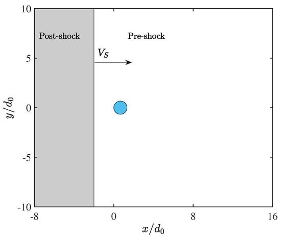
This article represents the natural continuation of the work by Rossano and De Stefano (2021), dealing with the computational fluid dynamics analysis of a shock wave interaction with a liquid droplet. Differently from our previous work, where a two-dimensional approach was followed, fully
[...] Read more.
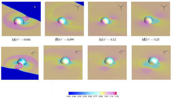
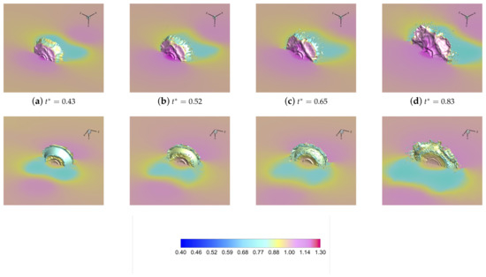
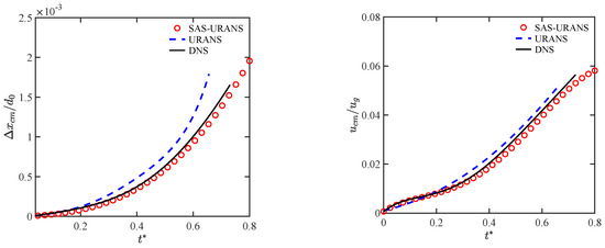
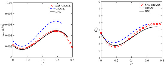
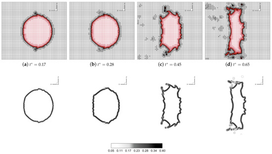
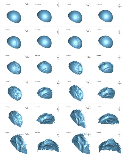
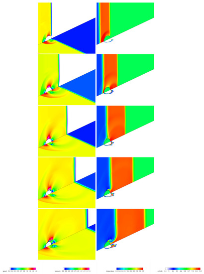
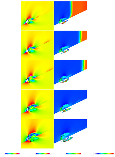
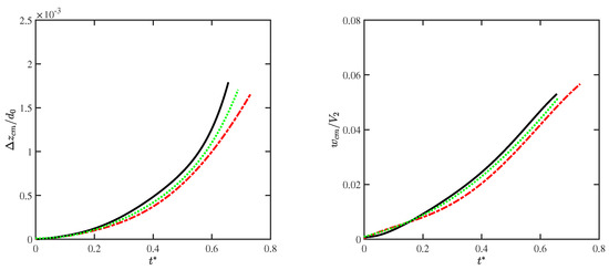
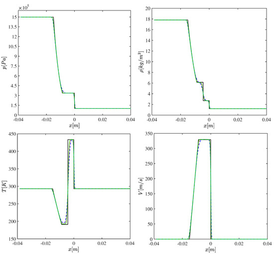
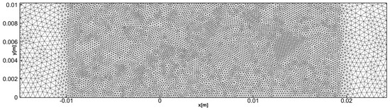
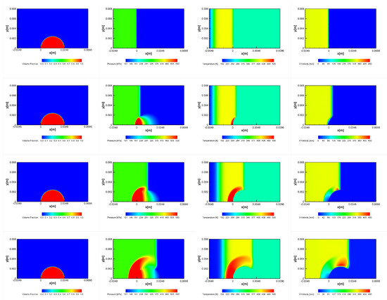
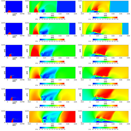
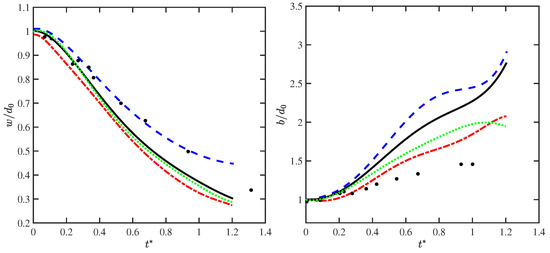
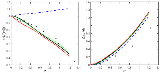
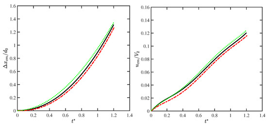
This article represents the natural continuation of the work by Rossano and De Stefano (2021), dealing with the computational fluid dynamics analysis of a shock wave interaction with a liquid droplet. Differently from our previous work, where a two-dimensional approach was followed, fully three-dimensional computations are performed to predict the aerodynamic breakup of a spherical water body due to the impact of a traveling shock wave. The present engineering analysis focuses on capturing the early stages of the breakup process under the shear-induced entrainment regime. The unsteady Reynolds-averaged Navier–Stokes approach is used to simulate the mean turbulent flow field in a virtual shock tube device with circular cross section. The compressible-flow-governing equations are numerically solved by means of a finite volume method, where the volume of fluid technique is employed to track the air–water interface. The proposed computational modeling approach for industrial gas dynamics applications is verified by making a comparison with reference numerical data and experimental findings, achieving acceptably accurate predictions of deformation and drift of the water body without being computationally cumbersome.
Full article
►▼
Show Figures
Open AccessArticle
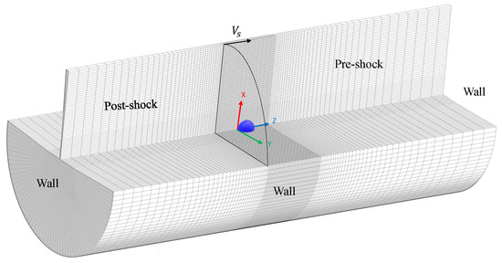
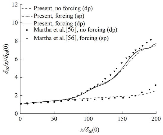
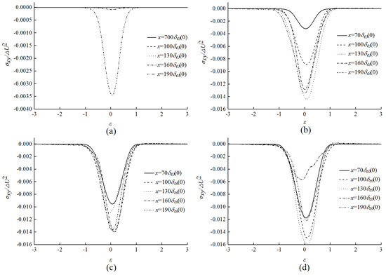
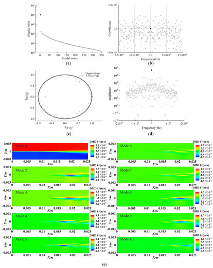
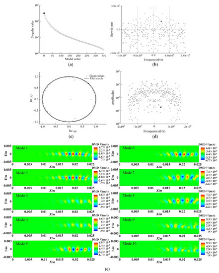
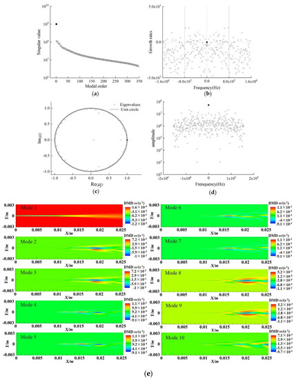
Large Eddy Simulation and Dynamic Mode Decomposition of Turbulent Mixing Layers
by
Yuwei Cheng and Qian Chen
Cited by 4 | Viewed by 2512
Abstract
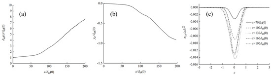
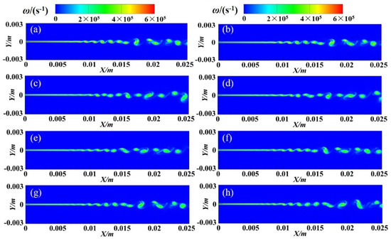
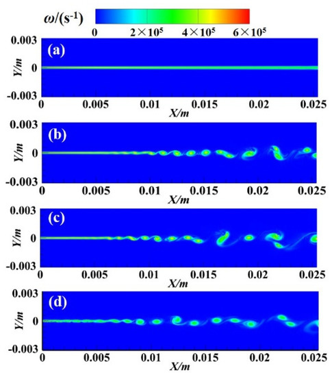
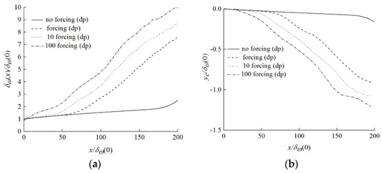
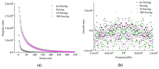
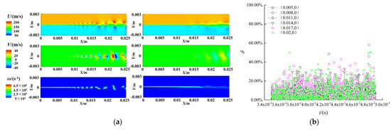
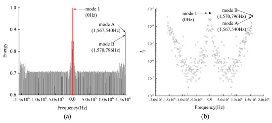
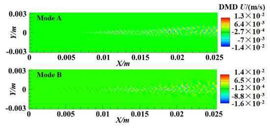
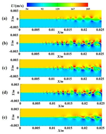
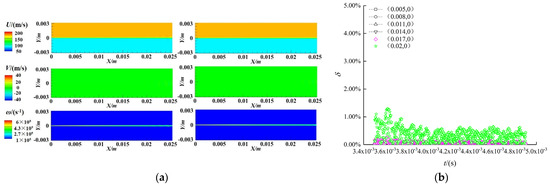
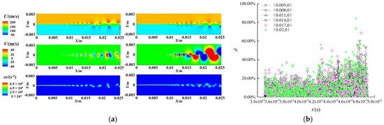
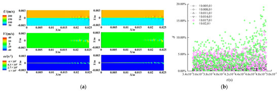
Turbulent mixing layers are canonical flow in nature and engineering, and deserve comprehensive studies under various conditions using different methods. In this paper, turbulent mixing layers are investigated using large eddy simulation and dynamic mode decomposition. The accuracy of the computations is verified
[...] Read more.
Turbulent mixing layers are canonical flow in nature and engineering, and deserve comprehensive studies under various conditions using different methods. In this paper, turbulent mixing layers are investigated using large eddy simulation and dynamic mode decomposition. The accuracy of the computations is verified and validated. Standard dynamic mode decomposition is utilized to flow decomposition, reconstruction and prediction. It was found that the dominant-mode selection criterion based on mode amplitude is more suitable for turbulent mixing layer flow compared with the other three criteria based on singular value, modal energy and integral modal amplitude, respectively. For the mixing layer with random disturbance, the standard dynamic mode decomposition method could accurately reconstruct and predict the region before instability happens, but is not qualified in the regions after that, which implies that improved dynamic mode decomposition methods need to be utilized or developed for the future dynamic mode decomposition of turbulent mixing layers.
Full article
►▼
Show Figures
Open AccessArticle
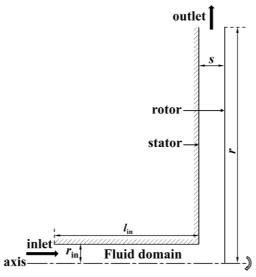
Effect of Rotational Speed Variation on the Flow Characteristics in the Rotor-Stator System Cavity
by
Zhizhou Zhao, Wenwu Song, Yongxin Jin and Jiaxing Lu
Cited by 4 | Viewed by 1822
Abstract
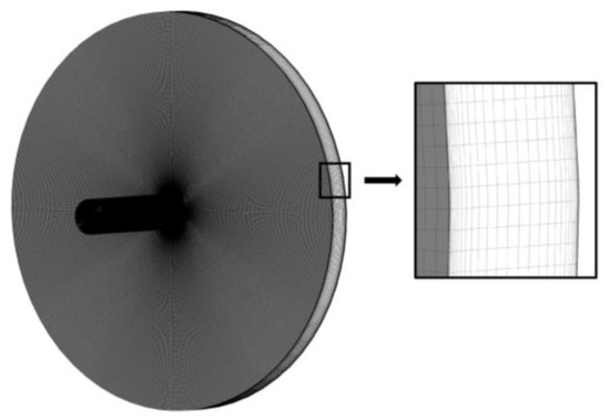
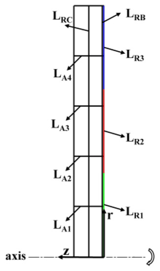
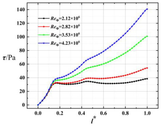
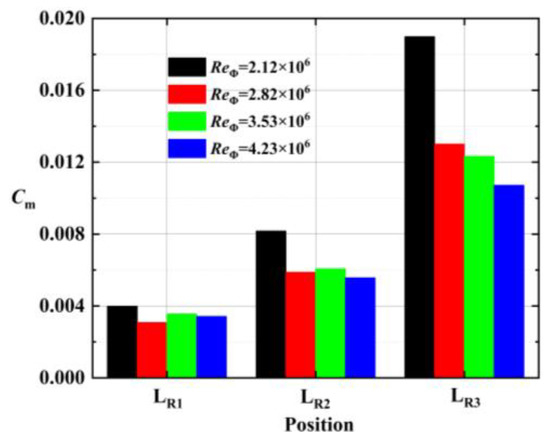
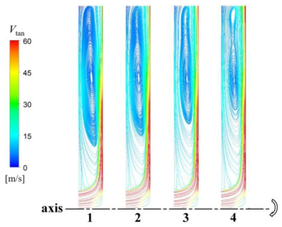
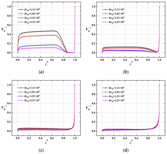
In this paper, to study the effect of dynamic and static interference of clearance flow in fluid machinery caused by changes in rotational speed, the model was simplified to a rotor-stator system cavity flow. Investigating the flow characteristics in the cavity by changing
[...] Read more.
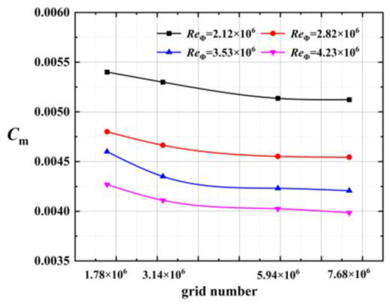
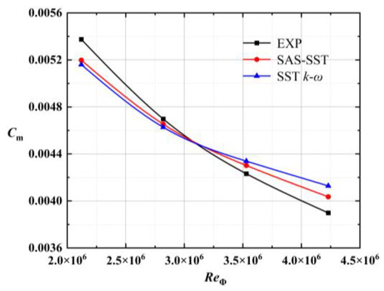
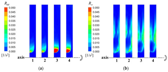
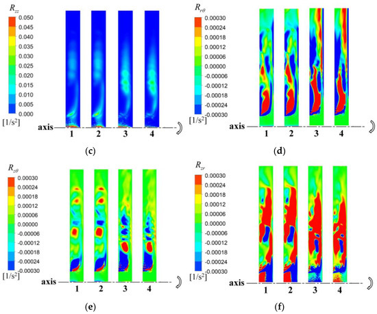
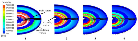
In this paper, to study the effect of dynamic and static interference of clearance flow in fluid machinery caused by changes in rotational speed, the model was simplified to a rotor-stator system cavity flow. Investigating the flow characteristics in the cavity by changing the rotor speed of the rotor-stator system is of considerable significance. ANSYS-CFX was applied to numerically simulate the test model and the results were compared with the experimental results of the windage torque of the rotor-stator system. The inlet flow rate and geometric model remained unchanged. With an increase in the rotating Reynolds number, the shear stress on the rotor wall gradually increased, and the maximum gradient was within
l* < 0.15. In addition to the shear stress, the tangential Reynolds stress
Rrθ contributed partly to the torque on the rotor wall. The swirling vortex formed by entrainment in the cavity of the rotor-stator system tended to separate at
ReΦ= 3.53 × 10
6. As the rotating Reynolds number continued to increase, the secondary vortex finally separated completely. The strength of the vortex in the rotor turbulent boundary layer decreased with an increase in the rotating speed, but the number of vortex cores increased with the increase of speed. Depending on the application of the fluid machine, controlling the rotating speed within a reasonable range can effectively improve the characteristics of the clearance flow.
Full article
►▼
Show Figures
Open AccessArticle
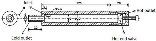
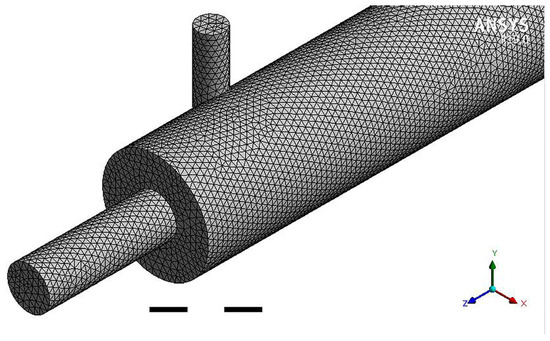
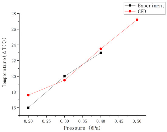
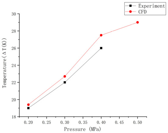
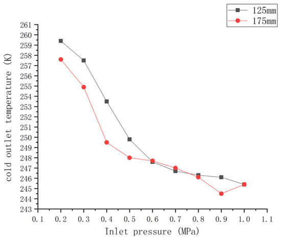
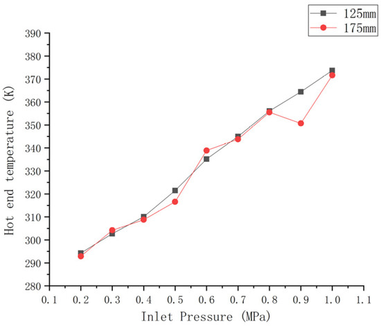
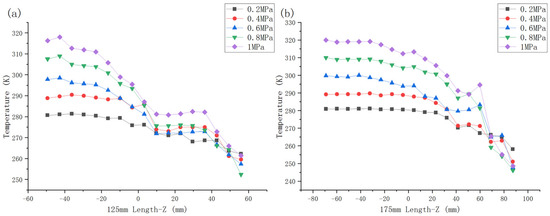
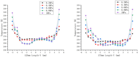
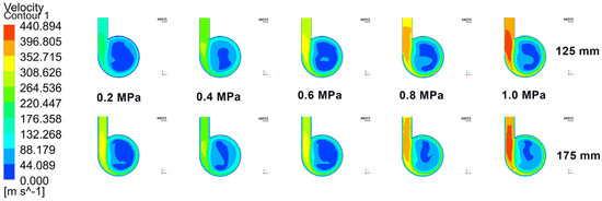
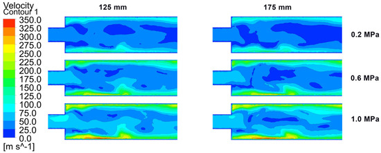
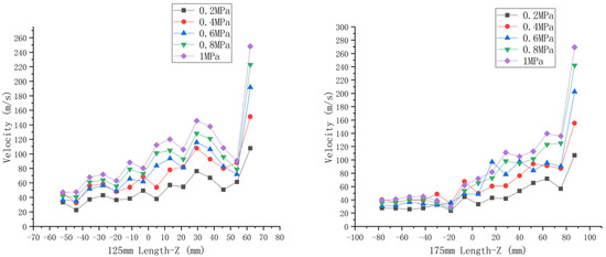
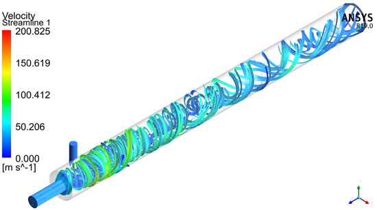
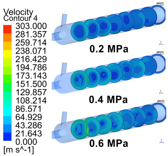
3D Numerical Simulation and Performance Analysis of CO2 Vortex Tubes
by
Qijun Xu, Jinfeng Wang and Jing Xie
Cited by 2 | Viewed by 1696
Abstract
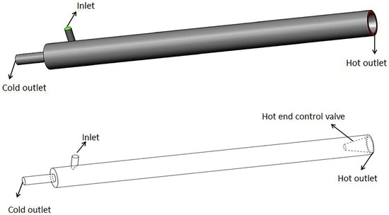
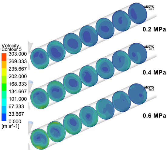
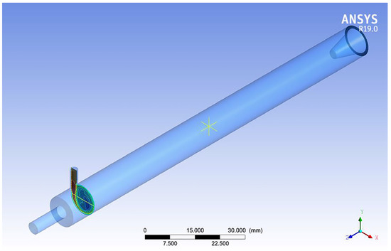
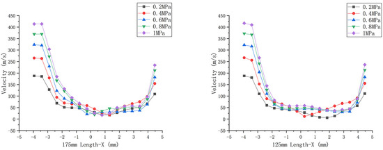
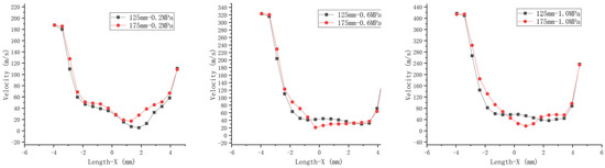
In view of the extensive application of swirl flow pipes (vortex tubes) in refrigeration systems, the parameters of swirl flow pipes were investigated to provide optimal cooling and heating conditions. Three-dimensional numerical simulations were carried out using available experimental data and models. The
[...] Read more.
In view of the extensive application of swirl flow pipes (vortex tubes) in refrigeration systems, the parameters of swirl flow pipes were investigated to provide optimal cooling and heating conditions. Three-dimensional numerical simulations were carried out using available experimental data and models. The analysis verified that the heat pipe with a length of 175 mm performed better than the swirl flow pipe with a length of 125 mm, confirming experiments by Agrawal. Meanwhile, by comparing different pressures, it was found that in the single-nozzle swirl flow pipe, the greater the increase of pressure (0.1–1.0 MPa), the greater the burden on the vortex chamber and the more serious the wear is, which can be seen in the higher inlet pressure. In order to improve the durability of the swirl flow pipe, we suggest using a swirl flow pipe with more nozzles. Finally, according to the simulation results, with the rise of carbon dioxide pressure potential energy at the inlet, the cooling effect of the swirl flow is first increasing and then decreasing. When the swirl flow pipe is used as a refrigeration device to determine the minimum cooling temperature under the maximum pressure, the lowest temperature of the 125 mm swirl flow pipe was 252.4 K at 0.8 MPa, while the lowest temperature of the 175 mm swirl flow pipe was 246.0 K. Secondly, the distance from the inlet to the hot outlet of the swirl flow pipe had little effect on the cooling temperature and radial velocity, but increasing its distance increased the wall temperature of the swirl flow pipe because it increases the contact time between the airflow and the hot end of the tube wall. When the swirl flow pipe is used as a heat-producing device, increasing the tube length of the swirl flow pipe appropriately increases its maximum heat-producing temperature.
Full article
►▼
Show Figures
Open AccessArticle
A Semi-Empirical Fluid Dynamic Model of a Vacuum Microgripper Based on CFD Analysis
by
Dario Giuseppe Urbano, Gianmaria Noventa, Antonio Ghidoni and Adriano M. Lezzi
Cited by 2 | Viewed by 1488
Abstract
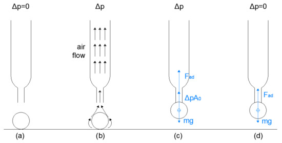
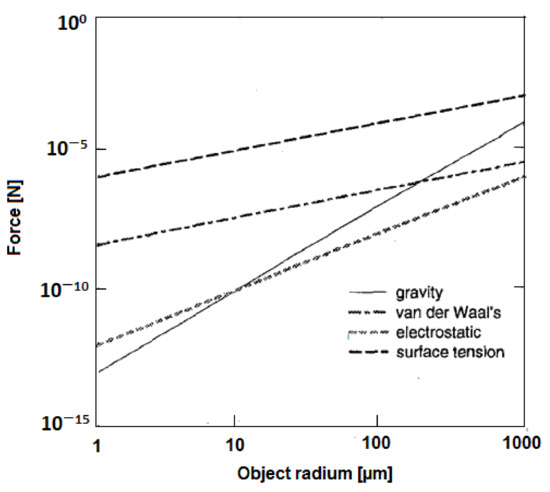
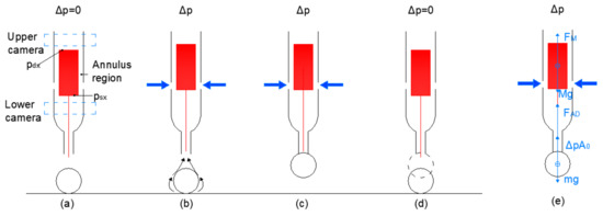
Vacuum microgrippers are devices used to handle and manipulate small objects. Despite their simple working principle and low cost, they show low efficiency in detaching performance, especially when the object to be grasped is very small. In this work, a particular design for
[...] Read more.
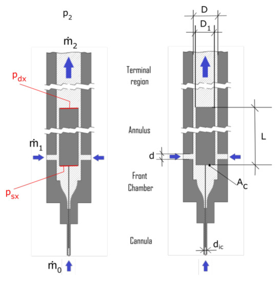
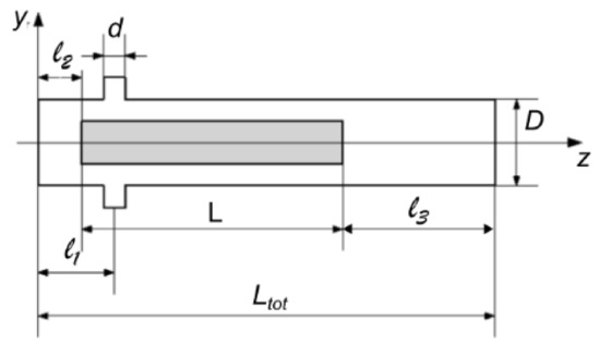
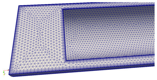
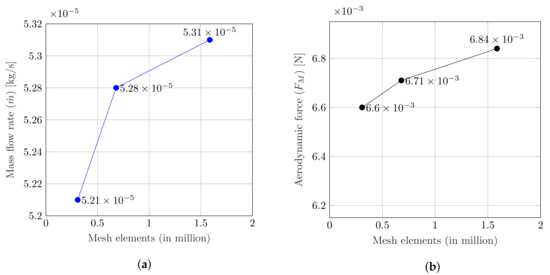
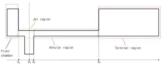
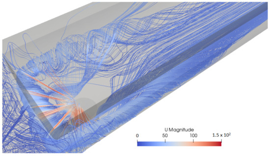
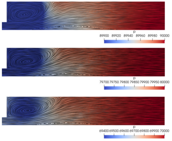
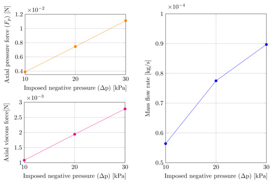
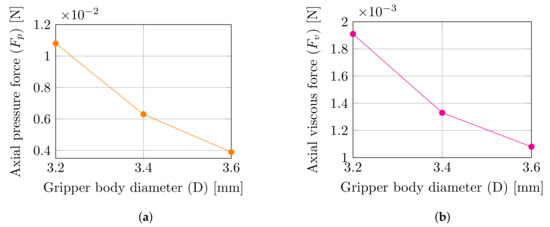
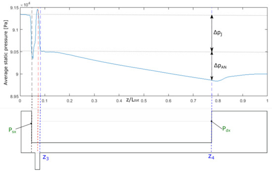
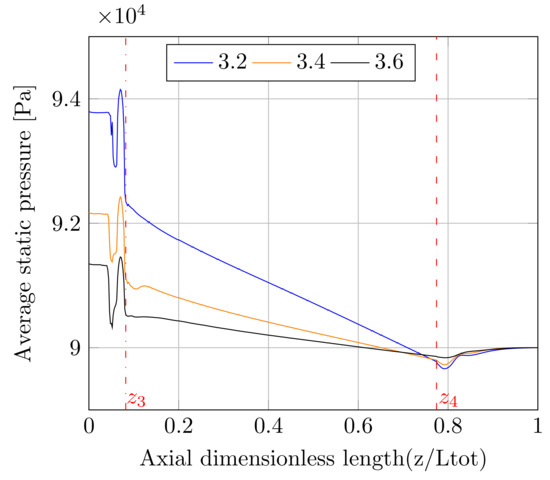
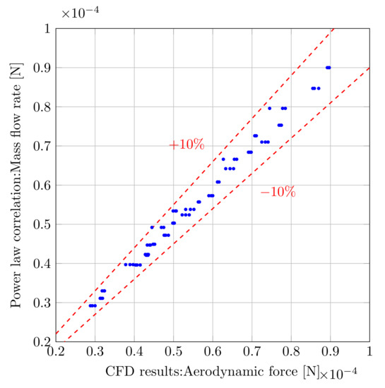
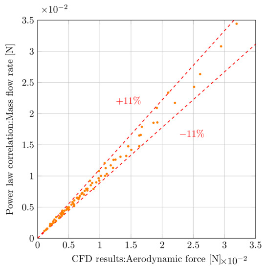
Vacuum microgrippers are devices used to handle and manipulate small objects. Despite their simple working principle and low cost, they show low efficiency in detaching performance, especially when the object to be grasped is very small. In this work, a particular design for vacuum microgrippers with an incorporated automatic release tool is considered. The final goal of this study was to present a numerical model that can supply reliable estimates of the aerodynamic force acting on the release tool and of the air flow rate inside the gripper as a function of geometric parameters and the outlet pressure value. A complete CFD analysis of a simplified model of the device is presented. Grid independence analysis was also performed to define a suitable grid and guarantee a good trade-off between accuracy and computing time. According to Design of Experiments (DOE) techniques, 81 simulations were performed, changing the values of the outlet pressure (
), the body inner diameter (
D), the lateral holes’ diameter (
d) and the releasing mass length (
L). Every design variable could assume three different values. Linear regression, based on the least square method, was employed to determine mass flow rate and lifting force empirical correlations.
Full article
►▼
Show Figures
Open AccessArticle
Spectral-Element Simulation of the Turbulent Flow in an Urban Environment
by
Maxime Stuck, Alvaro Vidal, Pablo Torres, Hassan M. Nagib, Candace Wark and Ricardo Vinuesa
Cited by 4 | Viewed by 2515
Abstract
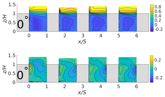
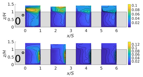
The mean flow and turbulence statistics of the flow through a simplified urban environment, which is an active research area in order to improve the knowledge of turbulent flow in cities, is investigated. This is useful for civil engineering, pedestrian comfort and for
[...] Read more.
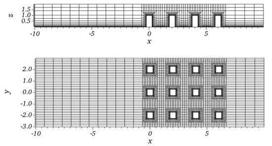
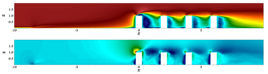
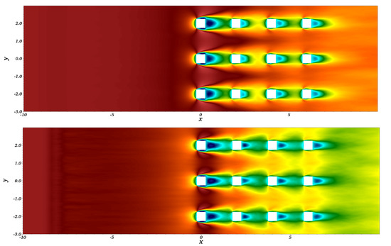
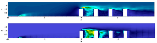
The mean flow and turbulence statistics of the flow through a simplified urban environment, which is an active research area in order to improve the knowledge of turbulent flow in cities, is investigated. This is useful for civil engineering, pedestrian comfort and for health concerns caused by pollutant spreading. In this work, we provide analysis of the turbulence statistics obtained from well-resolved large-eddy simulations (LES). A detailed analysis of this database reveals the impact of the geometry of the urban array on the flow characteristics and provides for a good description of the turbulent features of the flow within a simplified urban environment. The most prominent features of this complex flow include coherent vortical structures such as the so-called arch vortex, the horseshoe vortex and the roof vortex. These structures of flow have been identified by an analysis of the turbulence statistics. The influence of the geometry of urban environment (and particularly the street width and the building height) on the overall flow behavior has also been studied. Finally, the well-resolved LES results were compared with an available experimental database to discuss differences and similarities between the respective urban configurations.
Full article
►▼
Show Figures
Open AccessArticle
CFD Simulation of Solid Suspension for a Liquid–Solid Industrial Stirred Reactor
by
Adrian Stuparu, Romeo Susan-Resiga and Alin Bosioc
Cited by 10 | Viewed by 3577
Abstract
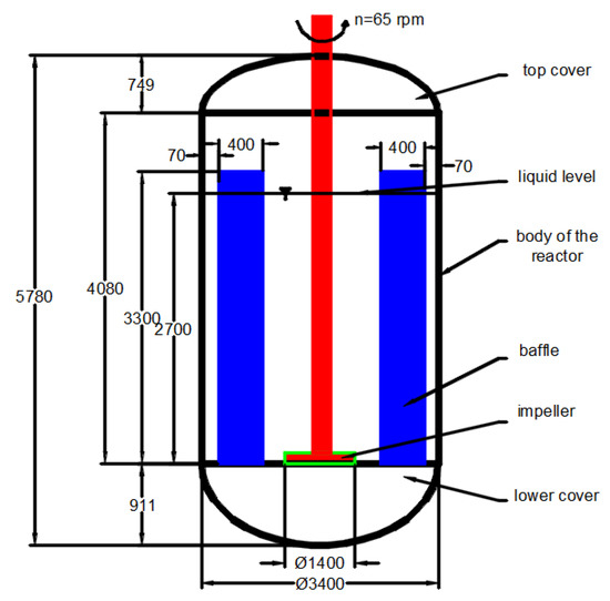
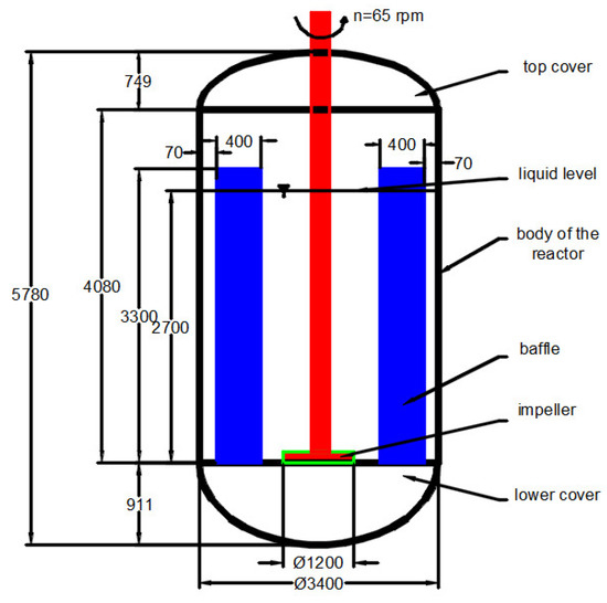
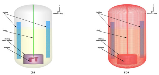
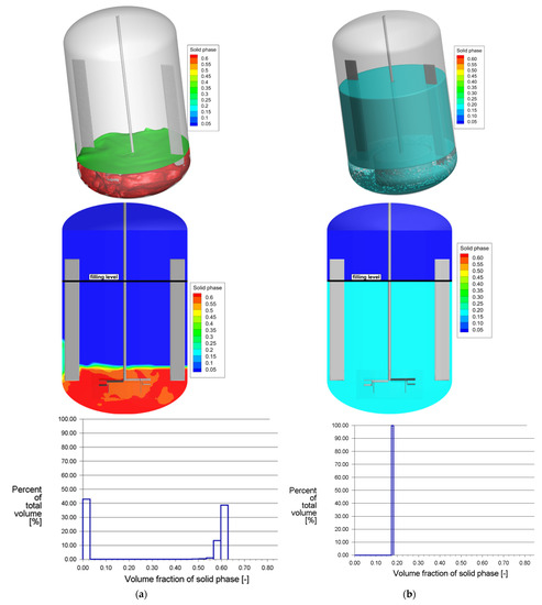
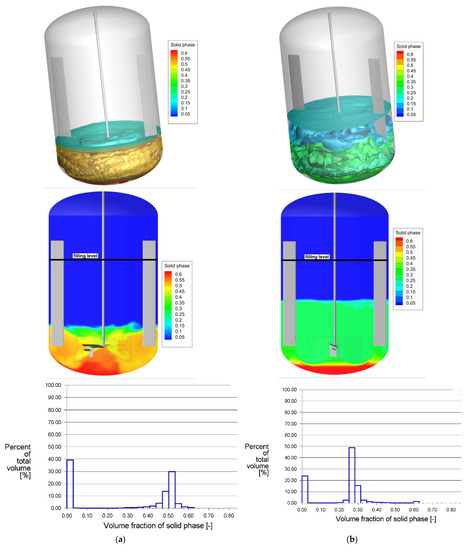
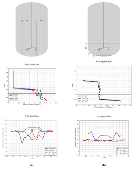
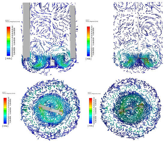
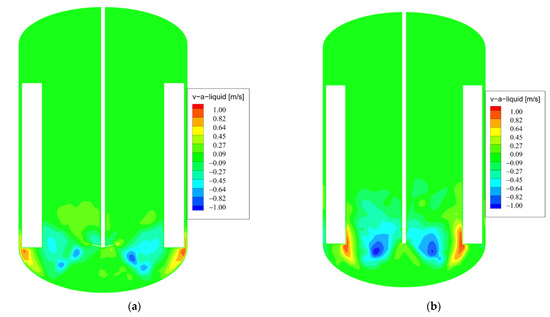
The present study examines the possibility of using an industrial stirred chemical reactor, originally employed for liquid–liquid mixtures, for operating with two-phase liquid–solid suspensions. It is critical when obtaining a high-quality chemical product that the solid phase remains suspended in the liquid phase
[...] Read more.
The present study examines the possibility of using an industrial stirred chemical reactor, originally employed for liquid–liquid mixtures, for operating with two-phase liquid–solid suspensions. It is critical when obtaining a high-quality chemical product that the solid phase remains suspended in the liquid phase long enough that the chemical reaction takes place. The impeller was designed for the preparation of a chemical product with a prescribed composition. The present study aims at finding, using a numerical simulation analysis, if the performance of the original impeller is suitable for obtaining a new chemical product with a different composition. The Eulerian multiphase model was employed along with the renormalization (RNG)
k-ε turbulence model to simulate liquid–solid flow with a free surface in a stirred tank. A sliding-mesh approach was used to model the impeller rotation with the commercial CFD code, FLUENT. The results obtained underline that 25% to 40% of the solid phase is sedimented on the lower part of the reactor, depending on the initial conditions. It results that the impeller does not perform as needed; hence, the suspension time of the solid phase is not long enough for the chemical reaction to be properly completed.
Full article
►▼
Show Figures
Open AccessArticle
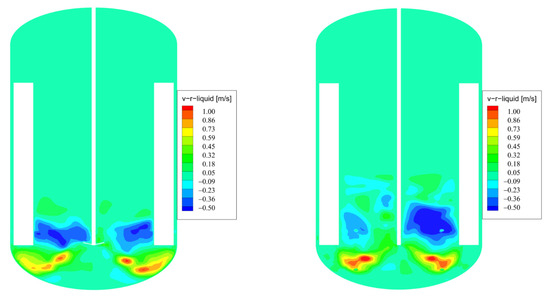
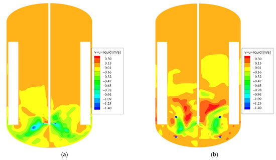
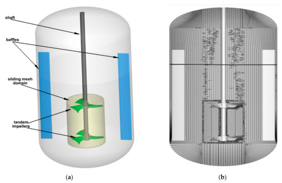
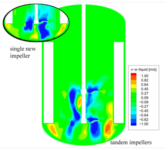
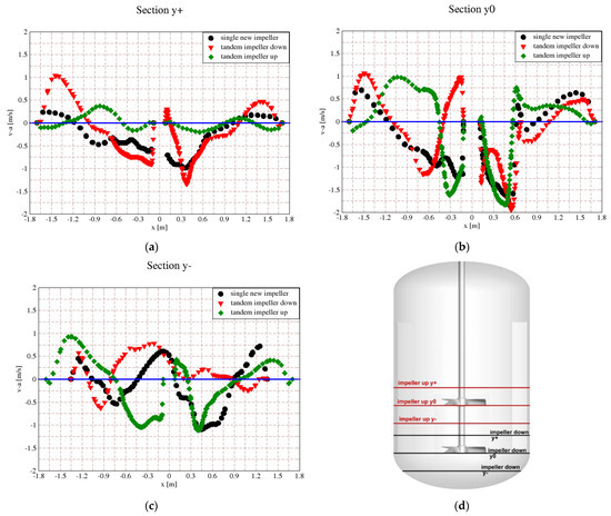
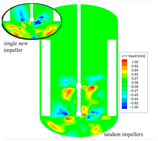
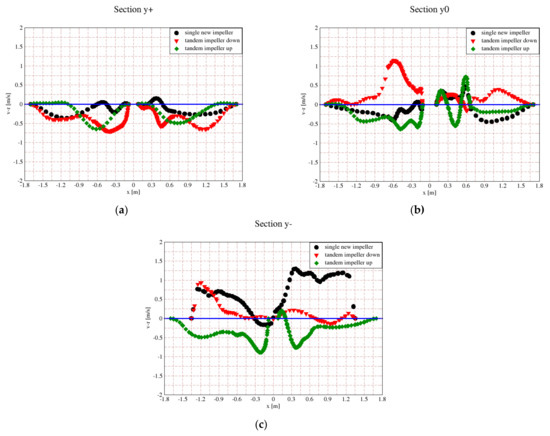
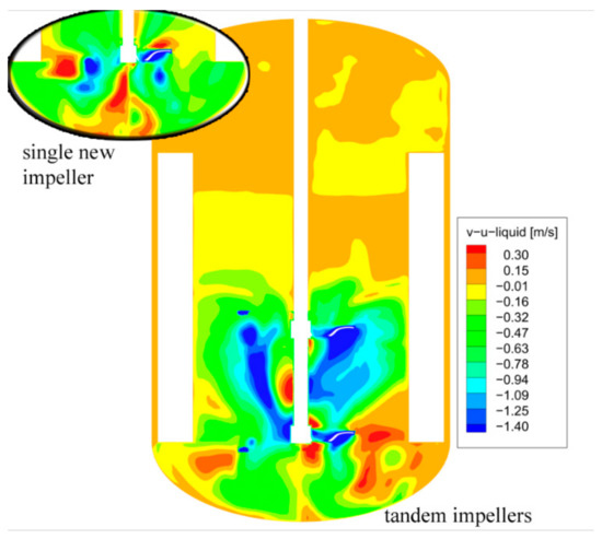
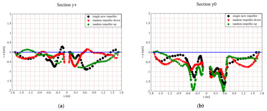
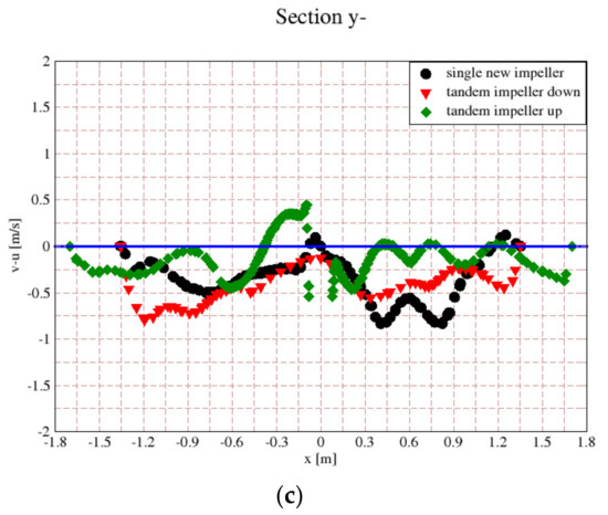
Improving the Homogenization of the Liquid-Solid Mixture Using a Tandem of Impellers in a Baffled Industrial Reactor
by
Adrian Stuparu, Romeo Susan-Resiga and Alin Bosioc
Cited by 1 | Viewed by 2293
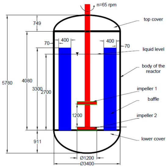
Abstract
The paper explores a tandem configuration of three-blade impellers in a stirred reactor. The working fluid is a liquid-solid mixture and the stirring mechanism fitted with the two impellers must prevent the sedimentation of solid particles while homogenously dispersing them in the bulk
[...] Read more.
The paper explores a tandem configuration of three-blade impellers in a stirred reactor. The working fluid is a liquid-solid mixture and the stirring mechanism fitted with the two impellers must prevent the sedimentation of solid particles while homogenously dispersing them in the bulk liquid. The present numerical investigation, performed with the expert software Ansys
® Fluent, Release 16, employs the Eulerian multiphase model along with the RNG k–ε turbulence model to simulate the free-surface liquid–solid flows in the baffled stirred reactor. A sliding mesh approach is used to model the impellers rotation. The tandem configuration is clearly superior to a single impeller, while the existing electrical motor that drives the stirring mechanism still provides the necessary power.
Full article
►▼
Show Figures
Open AccessArticle
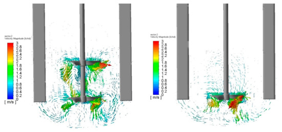
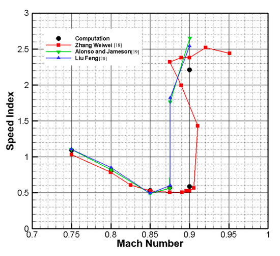
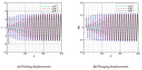
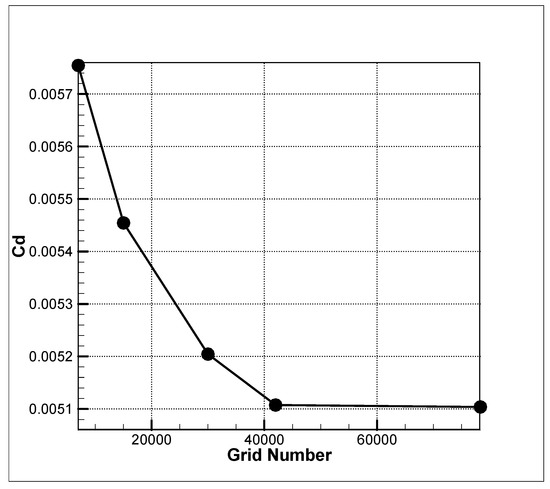
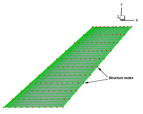
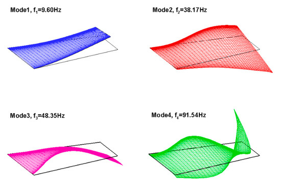
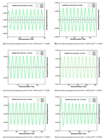
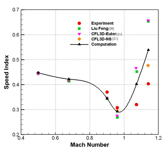
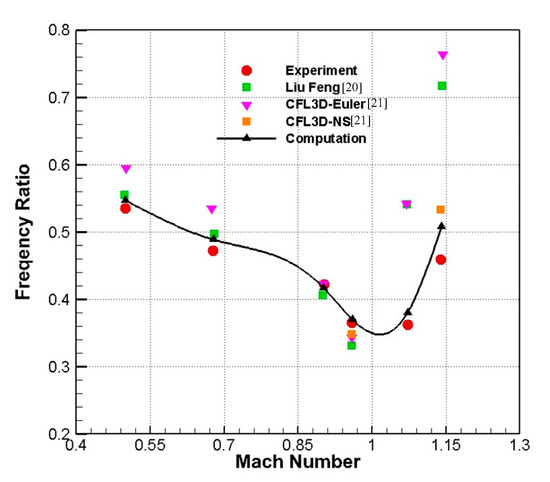
Time-Domain Aeroelasticity Analysis by a Tightly Coupled Fluid-Structure Interaction Methodology
by
Zhongyu Liu, Xueyuan Nie, Guannan Zheng and Guowei Yang
Cited by 1 | Viewed by 1973
Abstract
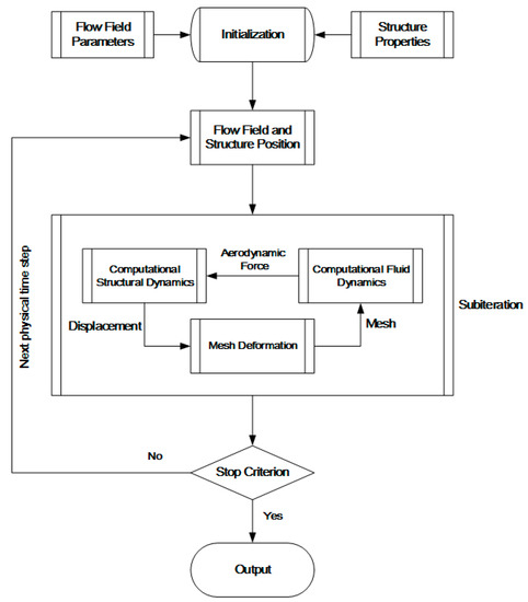
A tightly coupled fluid-structure interaction (FSI) methodology is developed for aeroelasticity analysis in the time domain. The preconditioned Navier–Stokes equations for all Mach numbers are employed and the structural equations are tightly coupled with the fluid equations by discretizing their time derivative term
[...] Read more.
A tightly coupled fluid-structure interaction (FSI) methodology is developed for aeroelasticity analysis in the time domain. The preconditioned Navier–Stokes equations for all Mach numbers are employed and the structural equations are tightly coupled with the fluid equations by discretizing their time derivative term in the same pseudo time-stepping method. A modified mesh deformation method based on reduced control points radial basis functions (RBF) is utilized, and a RBF based mapping algorithm is introduced for data exchange on the interaction interface. To evaluate the methodology, the flutter boundary and the limit cycle oscillation of Isogai wing and the flutter boundary of AGARD 445.6 wing are analyzed and validated.
Full article
►▼
Show Figures
Open AccessArticle
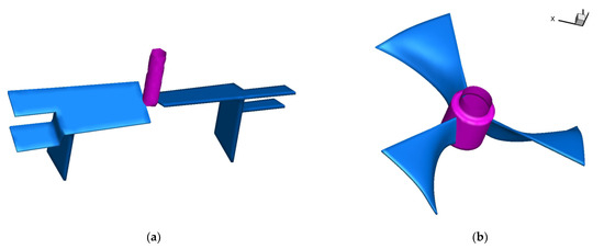
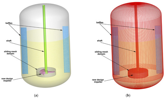
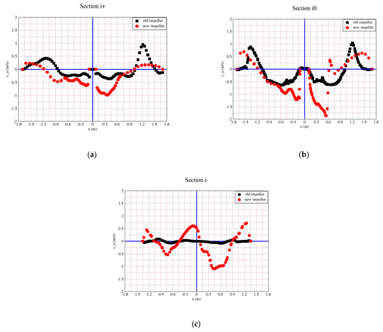
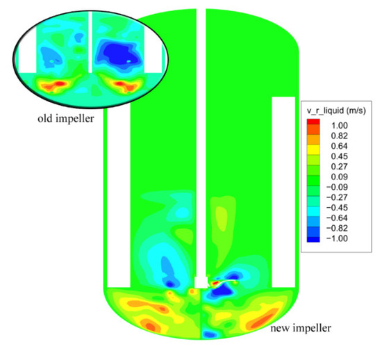
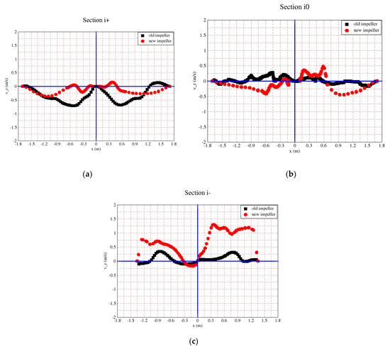
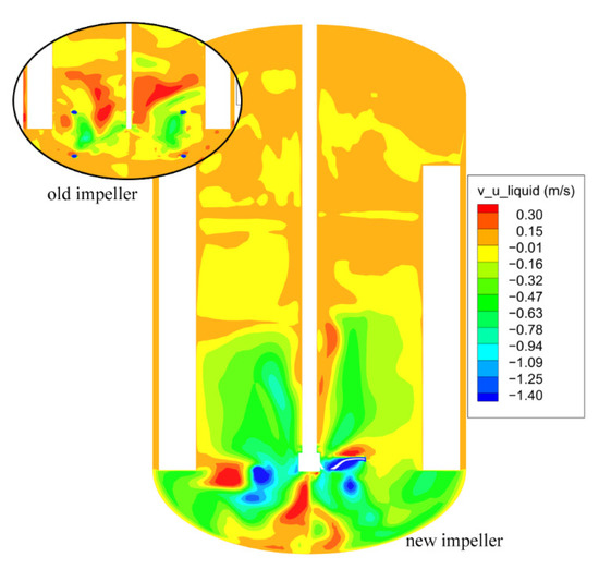
CFD Assessment of the Hydrodynamic Performance of Two Impellers for a Baffled Stirred Reactor
by
Adrian Stuparu, Romeo Susan-Resiga and Constantin Tanasa
Cited by 7 | Viewed by 2916
Abstract
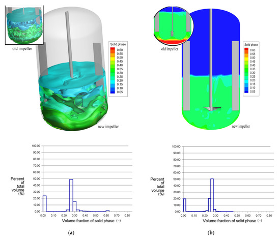
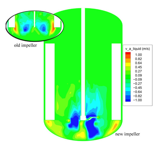
When converting a baffled stirred reactor to work with a different fluid, usually the original impeller must be replaced with a customized one. If the original impeller was designed for mixing liquids, its performance for liquid–solid suspensions may not be satisfactory. A case
[...] Read more.
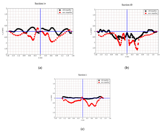
When converting a baffled stirred reactor to work with a different fluid, usually the original impeller must be replaced with a customized one. If the original impeller was designed for mixing liquids, its performance for liquid–solid suspensions may not be satisfactory. A case study is presented, where a two-blade original impeller is replaced with a new three-blade design. The new impeller shows clear improvements in mixing a liquid–solid suspension, while keeping the shaft power practically at the same level. As a result, a practically homogenous liquid–solid mixture is obtained, thus ensuring the required quality of the final product. The present numerical investigations employ the Eulerian multiphase model with renormalization (RNG) k–ε turbulence model to simulate the three-dimensional unsteady free-surface liquid–solid flow in a stirred tank. A sliding mesh approach was used to account for the impeller rotation within the expert code, FLUENT 16. The comparative quantitative analysis of the solid phase distribution and the relevant velocity profiles show that the new design of three-blade-impeller is significantly increasing the sedimentation time of the solid phase beyond the chemical reaction specific time. The necessary power to drive the new impeller has a slightly higher value than for the original impeller but it can be sustained by the existing driving system.
Full article
►▼
Show Figures
Open AccessArticle
Computational Evaluation of Shock Wave Interaction with a Cylindrical Water Column
by
Viola Rossano and Giuliano De Stefano
Cited by 4 | Viewed by 2135
Abstract
Computational fluid dynamics was employed to predict the early stages of the aerodynamic breakup of a cylindrical water column, due to the impact of a traveling plane shock wave. The unsteady Reynolds-averaged Navier–Stokes approach was used to simulate the mean turbulent flow in
[...] Read more.
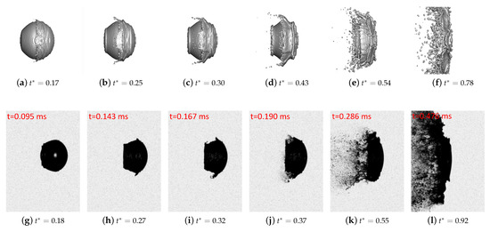
Computational fluid dynamics was employed to predict the early stages of the aerodynamic breakup of a cylindrical water column, due to the impact of a traveling plane shock wave. The unsteady Reynolds-averaged Navier–Stokes approach was used to simulate the mean turbulent flow in a virtual shock tube device. The compressible flow governing equations were solved by means of a finite volume-based numerical method, where the volume of fluid technique was employed to track the air–water interface on the fixed numerical mesh. The present computational modeling approach for industrial gas dynamics applications was verified by making a comparison with reference experimental and numerical results for the same flow configuration. The engineering analysis of the shock–column interaction was performed in the shear-stripping regime, where an acceptably accurate prediction of the interface deformation was achieved. Both column flattening and sheet shearing at the column equator were correctly reproduced, along with the water body drift.
Full article
►▼
Show Figures
Open AccessArticle
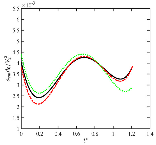
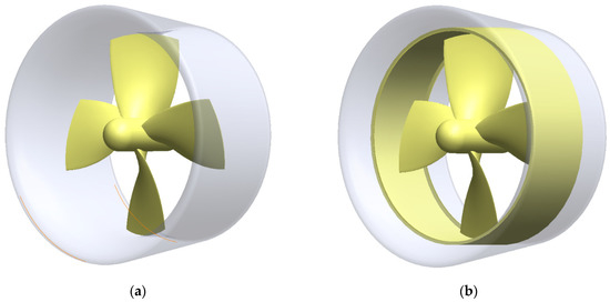
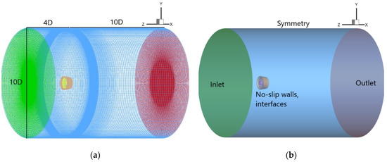
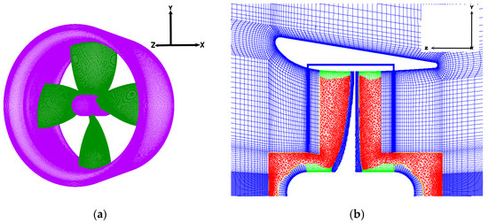
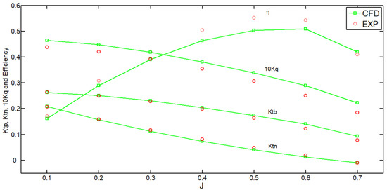
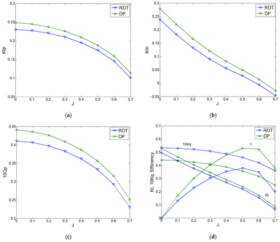
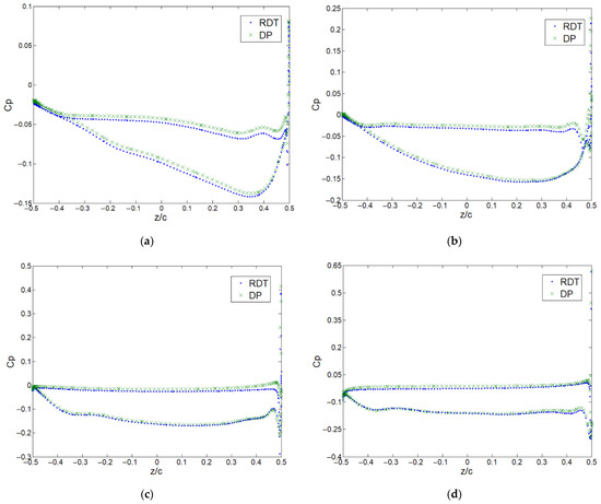
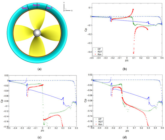
Numerical Study of the Hydrodynamic Characteristics Comparison between a Ducted Propeller and a Rim-Driven Thruster
by
Bao Liu and Maarten Vanierschot
Cited by 21 | Viewed by 3274
Abstract
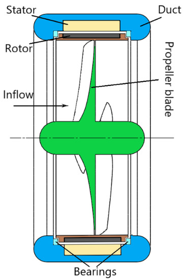
The Rim-Driven Thruster (RDT) is an extraordinary innovation in marine propulsion applications. The structure of an RDT resembles a Ducted Propeller (DP), as both contain several propeller blades and a duct shroud. However, unlike the DP, there is no tip clearance in the
[...] Read more.
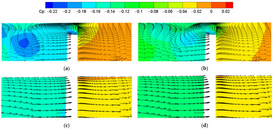
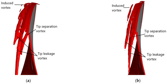
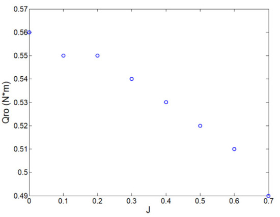
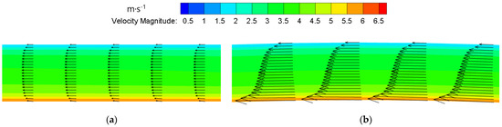
The Rim-Driven Thruster (RDT) is an extraordinary innovation in marine propulsion applications. The structure of an RDT resembles a Ducted Propeller (DP), as both contain several propeller blades and a duct shroud. However, unlike the DP, there is no tip clearance in the RDT as the propeller is directly connected to the rim. Instead, a gap clearance exists in the RDT between the rim and the duct. The distinctive difference in structure between the DP and the RDT causes significant discrepancy in the performance and flow features. The present work compares the hydrodynamic performance of a DP and an RDT by means of Computational Fluid Dynamics (CFD). Reynolds-Averaged Navier–Stokes (RANS) equations are solved in combination with an SST
k-ω turbulence model. Validation and verification of the CFD model is conducted to ensure the numerical accuracy. Steady-state simulations are carried out for a wide range of advance coefficients with the Moving Reference Frame (MRF) approach. The results show that the gap flow in the RDT plays an important role in affecting the performance. Compared to the DP, the RDT produces less thrust on the propeller and duct, and, because of the existence of the rim, the overall efficiency of the RDT is significantly lower than the one of the ducted propeller.
Full article
►▼
Show Figures
Open AccessArticle
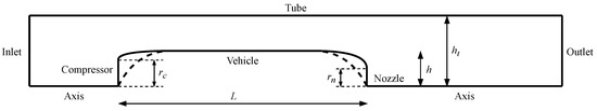
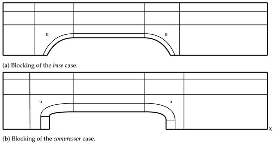
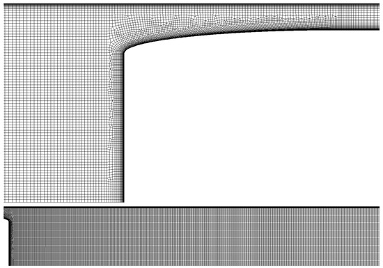
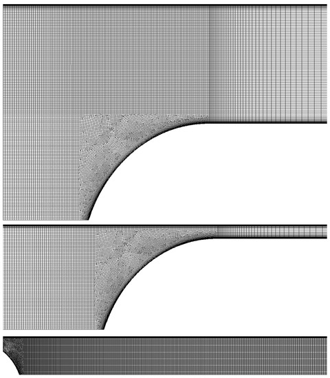
CFD Simulation of a Hyperloop Capsule Inside a Low-Pressure Environment Using an Aerodynamic Compressor as Propulsion and Drag Reduction Method
by
Federico Lluesma-Rodríguez, Temoatzin González and Sergio Hoyas
Cited by 12 | Viewed by 2915
Abstract
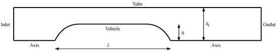
One of the most restrictive conditions in ground transportation at high speeds is aerodynamic drag. This is even more problematic when running inside a tunnel, where compressible phenomena such as wave propagation, shock waves, or flow blocking can happen. Considering Evacuated-Tube Trains (ETTs)
[...] Read more.
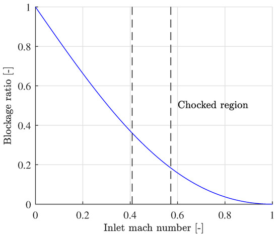
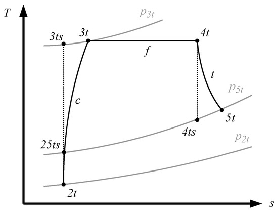
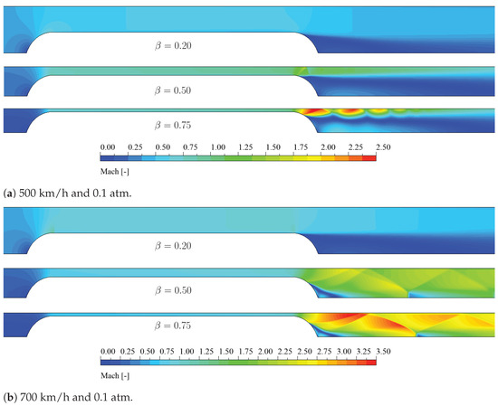
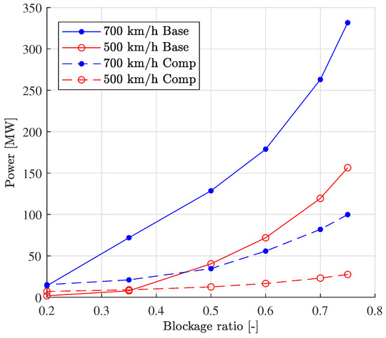
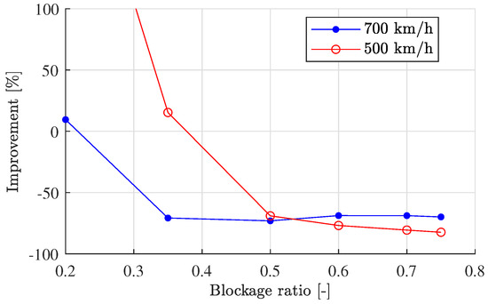
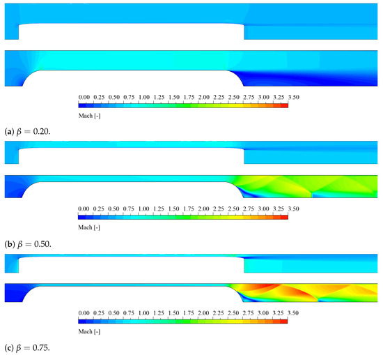
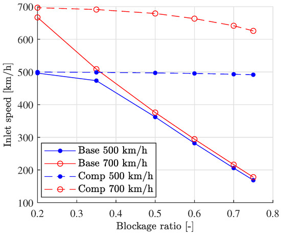
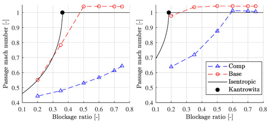
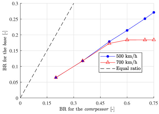
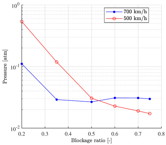
One of the most restrictive conditions in ground transportation at high speeds is aerodynamic drag. This is even more problematic when running inside a tunnel, where compressible phenomena such as wave propagation, shock waves, or flow blocking can happen. Considering Evacuated-Tube Trains (ETTs) or hyperloops, these effects appear during the whole route, as they always operate in a closed environment. Then, one of the concerns is the size of the tunnel, as it directly affects the cost of the infrastructure. When the tube size decreases with a constant section of the vehicle, the power consumption increases exponentially, as the Kantrowitz limit is surpassed. This can be mitigated when adding a compressor to the vehicle as a means of propulsion. The turbomachinery increases the pressure of part of the air faced by the vehicle, thus delaying the critical conditions on surrounding flow. With tunnels using a blockage ratio of 0.5 or higher, the reported reduction in the power consumption is 70%. Additionally, the induced pressure in front of the capsule became a negligible effect. The analysis of the flow shows that the compressor can remove the shock waves downstream and thus allows operation above the Kantrowitz limit. Actually, for a vehicle speed of 700 km/h, the case without a compressor reaches critical conditions at a blockage ratio of 0.18, which is a tunnel even smaller than those used for High-Speed Rails (0.23). When aerodynamic propulsion is used, sonic Mach numbers are reached above a blockage ratio of 0.5. A direct effect is that cases with turbomachinery can operate in tunnels with blockage ratios even 2.8 times higher than the non-compressor cases, enabling a considerable reduction in the size of the tunnel without affecting the performance. This work, after conducting bibliographic research, presents the geometry, mesh, and setup. Later, results for the flow without compressor are shown. Finally, it is discussed how the addition of the compressor improves the flow behavior and power consumption of the case.
Full article
►▼
Show Figures
Open AccessArticle
Experimental Assessment of RANS Models for Wind Load Estimation over Solar-Panel Arrays
by
Alejandro Güemes, Pablo Fajardo and Marco Raiola
Cited by 3 | Viewed by 1785
Abstract
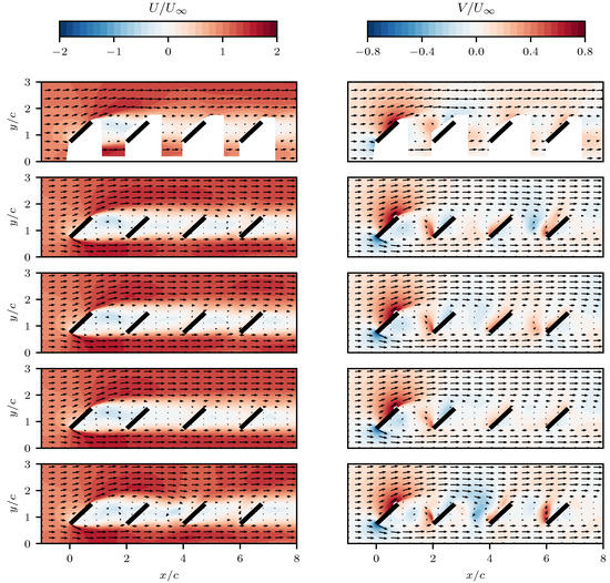
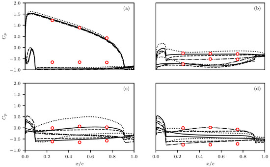
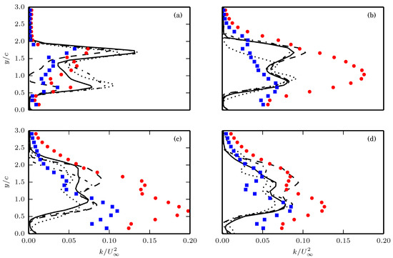
This paper reports a comparison between wind-tunnel measurements and numerical simulations to assess the capabilities of Reynolds-Averaged Navier-Stokes models to estimate the wind load over solar-panel arrays. The free airstream impinging on solar-panel arrays creates a complex separated flow at large Reynolds number,
[...] Read more.
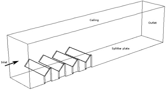
This paper reports a comparison between wind-tunnel measurements and numerical simulations to assess the capabilities of Reynolds-Averaged Navier-Stokes models to estimate the wind load over solar-panel arrays. The free airstream impinging on solar-panel arrays creates a complex separated flow at large Reynolds number, which is severely challenging for the current Reynolds-Averaged Navier-Stokes models. The Reynolds-Averaged Navier-Stokes models compared in this article are
k-
, Shear-Stress Transport
k-
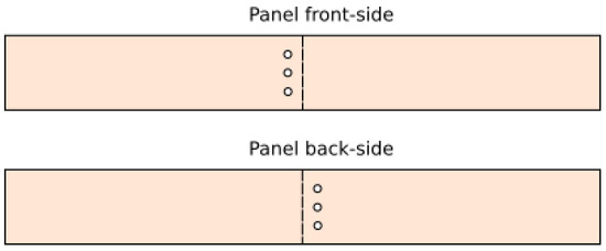
, transition and Reynolds Shear Model. Particle Image Velocimetry measurements are performed to investigate the mean flow-velocity and turbulent-kinetic-energy fields. Pressure taps are located in the surface of the solar panel model in order to obtain static pressure measurements. All the Reynolds-Averaged Navier-Stokes models predict accurate average velocity fields when compared with the experimental ones. One of the challenging factor is to predict correctly the thickness of the turbulent wake. In this aspect, Reynolds Shear provides the best results, reproducing the wake shrink observed on the 3rd panel in the experiment. On the other hand, some other features, most notably the blockage encountered by the flow below the panels, are not correctly reproduced by any of the models. The pressure distributions over the 1st panel obtained from the different Reynolds-Averaged Navier-Stokes models show good agreement with the pressure measurements. However, for the rest of the panels Reynolds-Averaged Navier-Stokes fidelity is severely challenged. Overall, the Reynolds Shear model provides the best pressure estimation in terms of pressure difference between the front and back sides of the panels.
Full article
►▼
Show Figures
Open AccessArticle
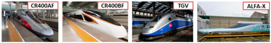
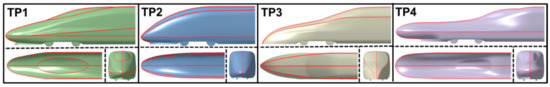
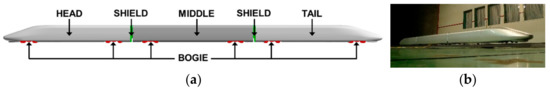
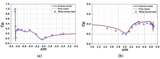
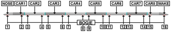
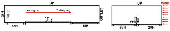
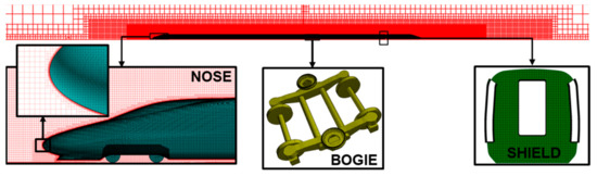
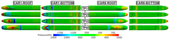
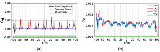
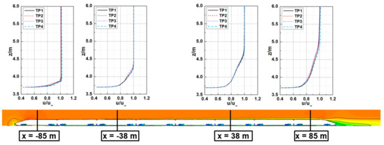
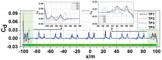
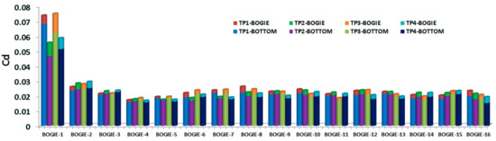
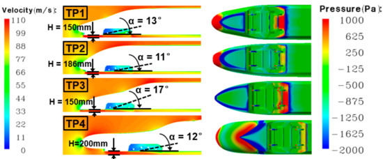
Numerical Investigation on the Influence of the Streamlined Structures of the High-Speed Train’s Nose on Aerodynamic Performances
by
Zhenxu Sun, Shuanbao Yao, Lianyi Wei, Yongfang Yao and Guowei Yang
Cited by 15 | Viewed by 7684
Abstract
The structural design of the streamlined shape is the basis for high-speed train aerodynamic design. With use of the delayed detached-eddy simulation (DDES) method, the influence of four different structural types of the streamlined shape on aerodynamic performance and flow mechanism was investigated.
[...] Read more.
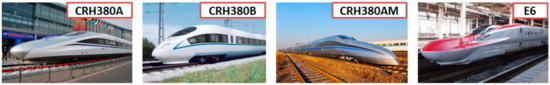
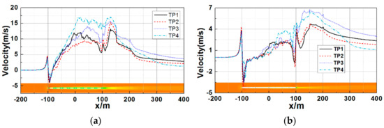
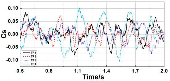
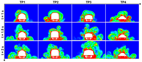
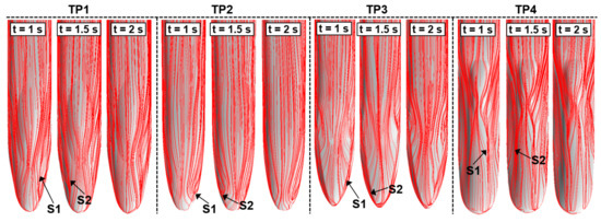
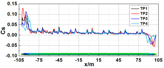
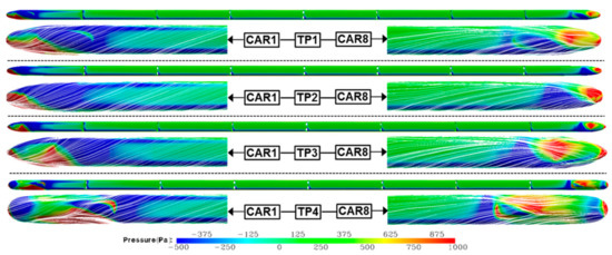
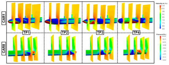
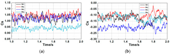
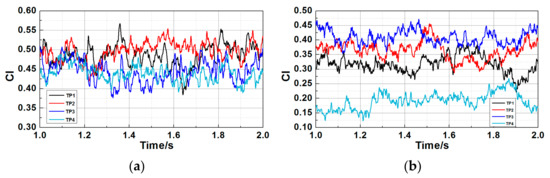
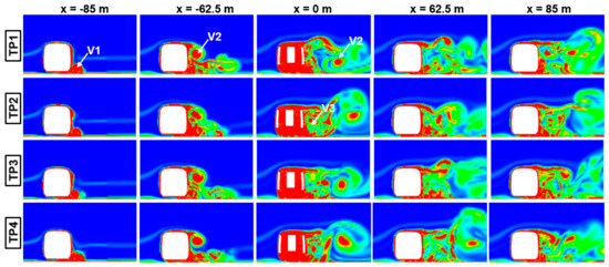
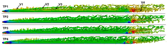
The structural design of the streamlined shape is the basis for high-speed train aerodynamic design. With use of the delayed detached-eddy simulation (DDES) method, the influence of four different structural types of the streamlined shape on aerodynamic performance and flow mechanism was investigated. These four designs were chosen elaborately, including a double-arch ellipsoid shape, a single-arch ellipsoid shape, a spindle shape with a front cowcatcher and a double-arch wide-flat shape. Two different running scenes, trains running in the open air or in crosswind conditions, were considered. Results reveal that when dealing with drag reduction of the whole train running in the open air, it needs to take into account how air resistance is distributed on both noses and then deal with them both rather than adjust only the head or the tail. An asymmetrical design is feasible with the head being a single-arch ellipsoid and the tail being a spindle with a front cowcatcher to achieve the minimum drag reduction. The single-arch ellipsoid design on both noses could aid in moderating the transverse amplitude of the side force on the tail resulting from the asymmetrical vortex structures in the flow field behind the tail. When crosswind is considered, the pressure distribution on the train surface becomes more disturbed, resulting in the increase of the side force and lift. The current study reveals that the double-arch wide-flat streamlined design helps to alleviate the side force and lift on both noses. The magnitude of side force on the head is 10 times as large as that on the tail while the lift on the head is slightly above that on the tail. Change of positions where flow separation takes place on the streamlined part is the main cause that leads to the opposite behaviors of pressure distribution on the head and on the tail. Under the influence of the ambient wind, flow separation occurs about distinct positions on the train surface and intricate vortices are generated at the leeward side, which add to the aerodynamic loads on the train in crosswind conditions. These results could help gain insight on choosing a most suitable streamlined shape under specific running conditions and acquiring a universal optimum nose shape as well.
Full article
►▼
Show Figures
Open AccessArticle
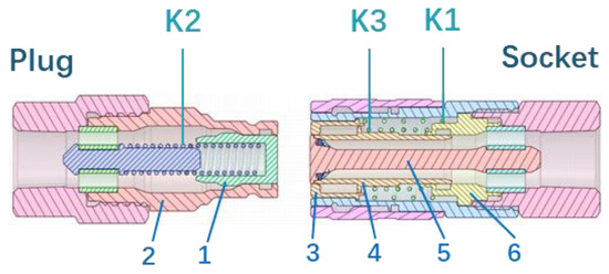
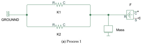
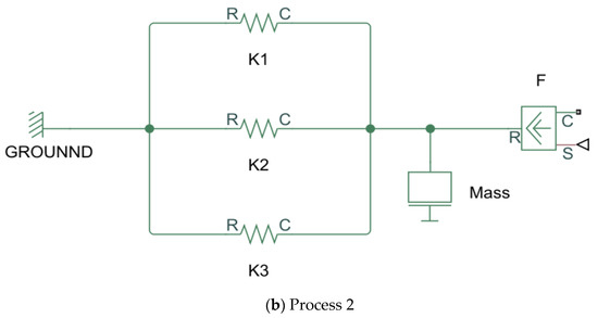
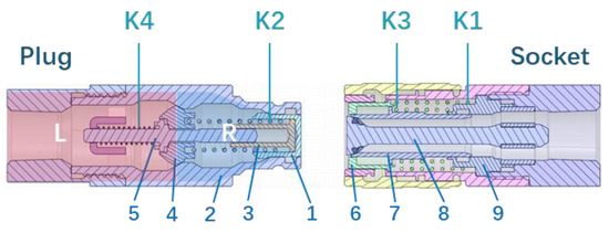
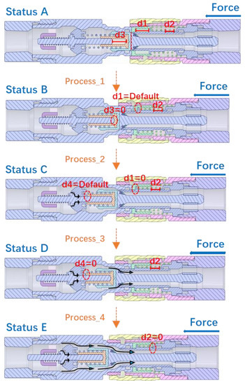
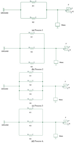
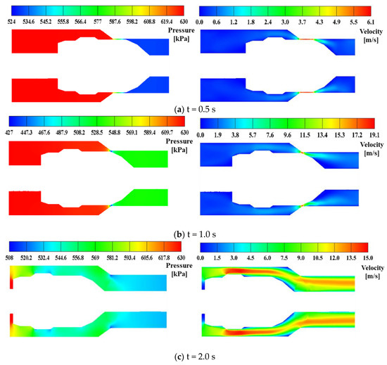
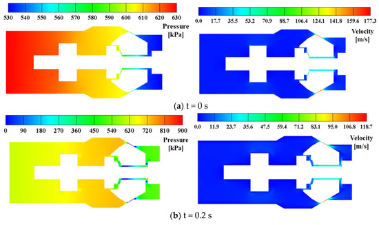
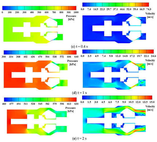
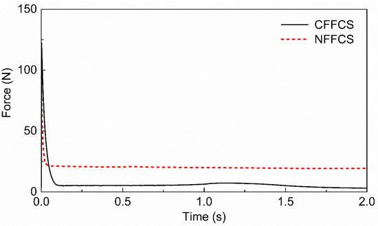
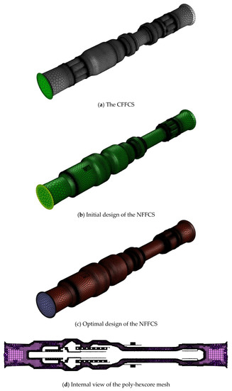
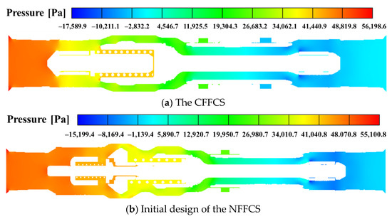
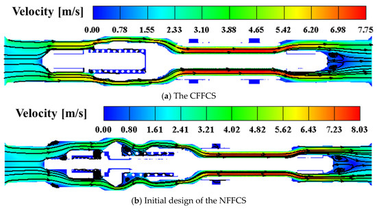
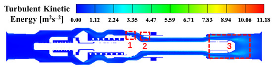
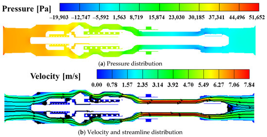
Design and Numerical Simulation-Based Optimization of a Novel Flat-Face Coupling System for Hydraulic Power Equipment
by
Yu-Ting Wu, Zhen Qin, Amre Eizad and Sung-Ki Lyu
Cited by 7 | Viewed by 2241
Abstract
Coupling systems play a vital role in hydraulic power transmission equipment. In recent years, flat-face coupling systems have been extensively studied due to their environment friendly features. The difficulty of the connection process of hydraulic equipment increases with the increase in their working
[...] Read more.
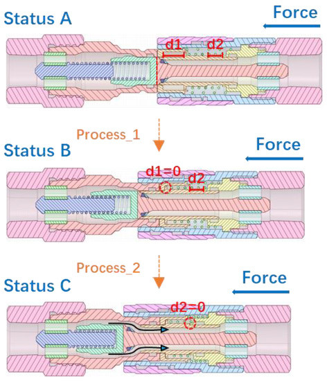
Coupling systems play a vital role in hydraulic power transmission equipment. In recent years, flat-face coupling systems have been extensively studied due to their environment friendly features. The difficulty of the connection process of hydraulic equipment increases with the increase in their working pressure. To improve the convenience of making high-pressure connections, a novel flat-face coupling system is proposed in this article. In the proposed design, which is based on the conventional flat-face coupling system, the resistance caused by high hydraulic fluid pressure during coupling is drastically reduced by the addition of an instantaneous pressure relief module. In this study, the theoretical model of the system kinetics is established to illustrate the operational mechanism of the novel design, and a series of computational fluid dynamics numerical investigations based on the novel dynamic mesh technology and Ansys Mosaic meshing technology are implemented to verify the rationality of the proposed design. Additionally, an optimal design of the novel flat-face coupling system is proposed to reduce the energy loss during hydraulic power transmission.
Full article
►▼
Show Figures


