

An Agile Model-Based Software Engineering Approach Illustrated through the Development of a Health Technology System

Abstract
:1. Introduction
2. Background
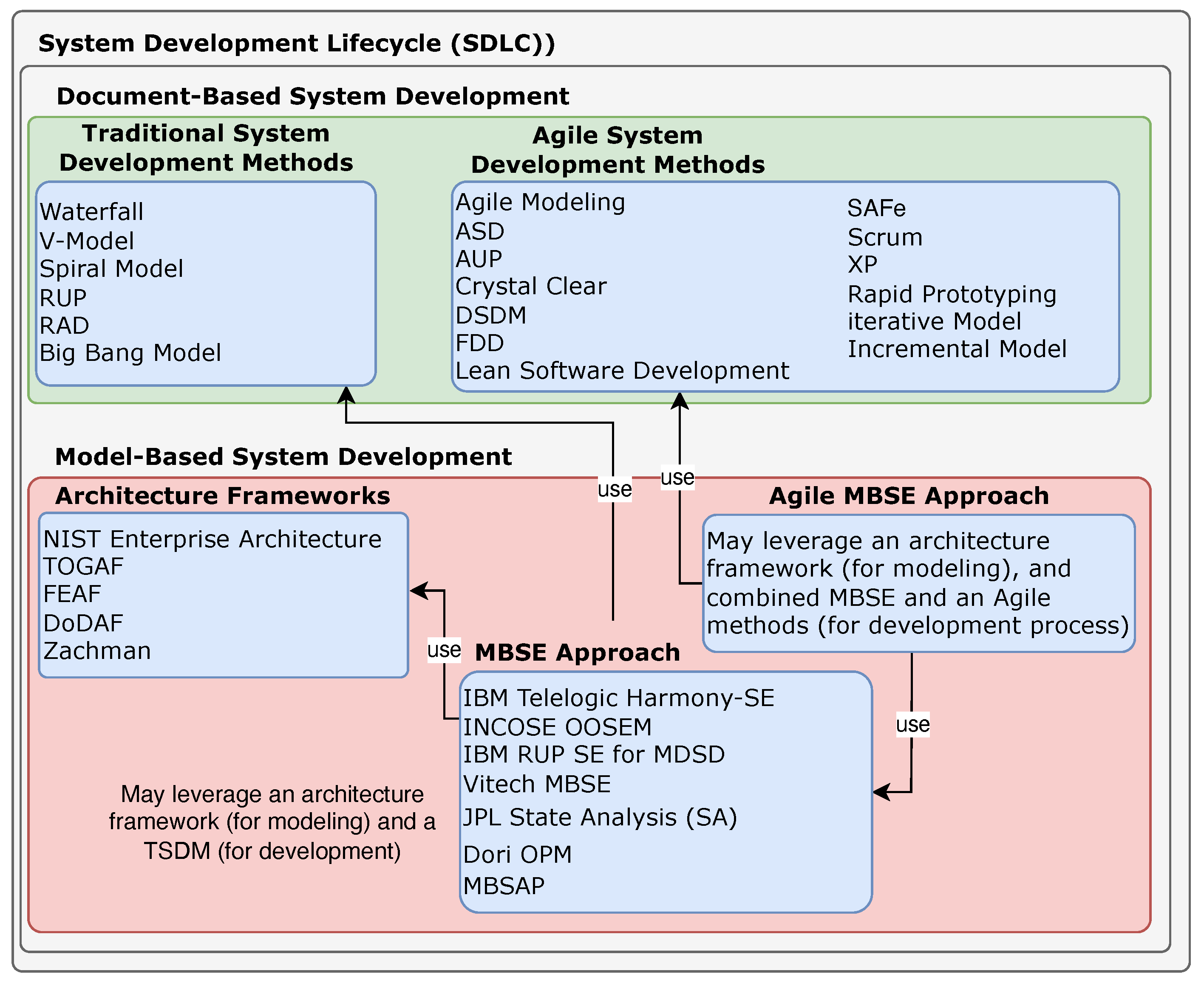
2.1. Software Development Lifecycle (SDLC)
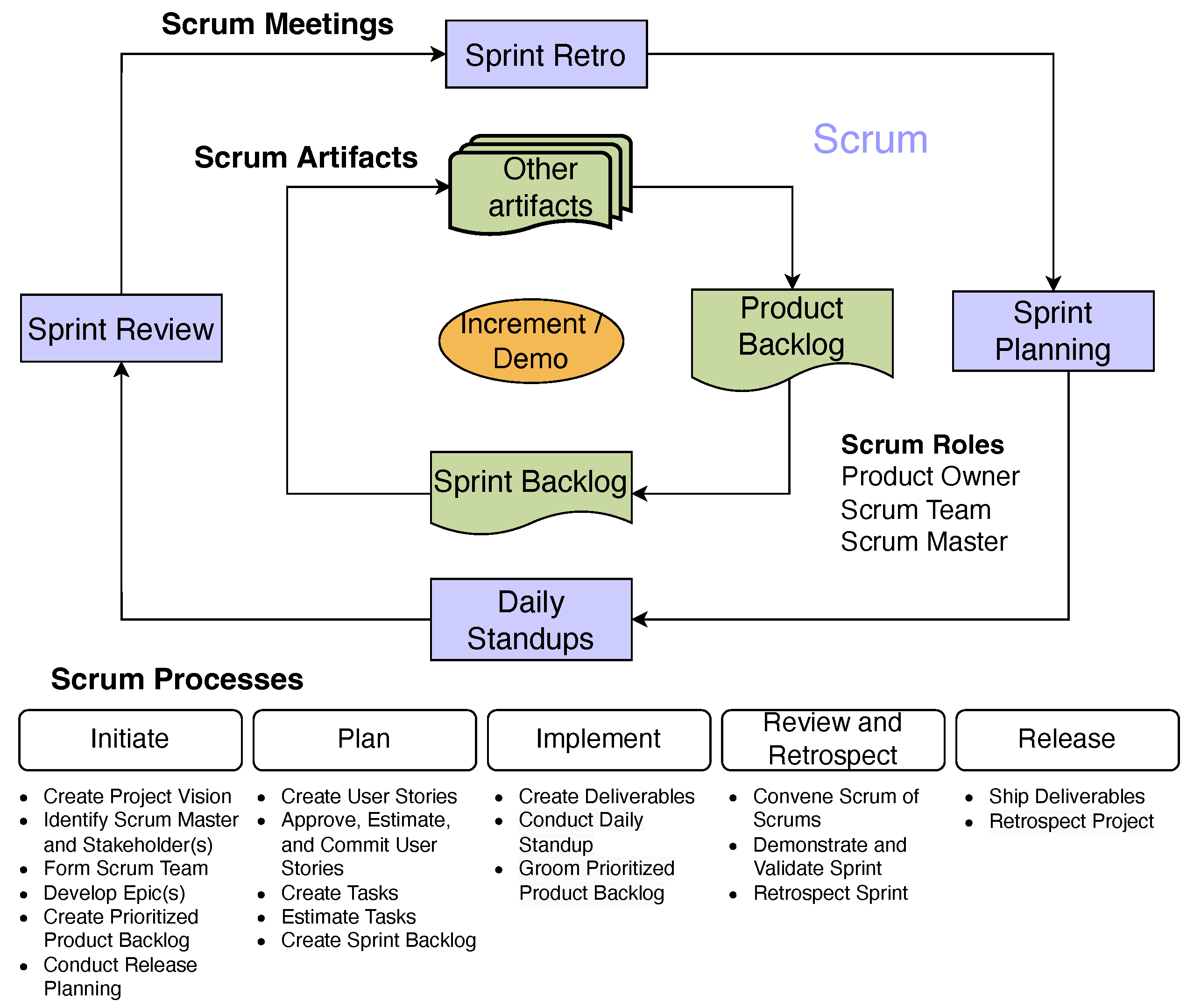
2.2. Scrum Method
2.3. Model-Based Software Engineering (MBSE)
Model-Based System Architecture Process (MBSAP)
2.4. Agile MBSE
3. Integrated Scrum Model-Based System Architecture Process (sMBSAP)
3.1. Research Methods
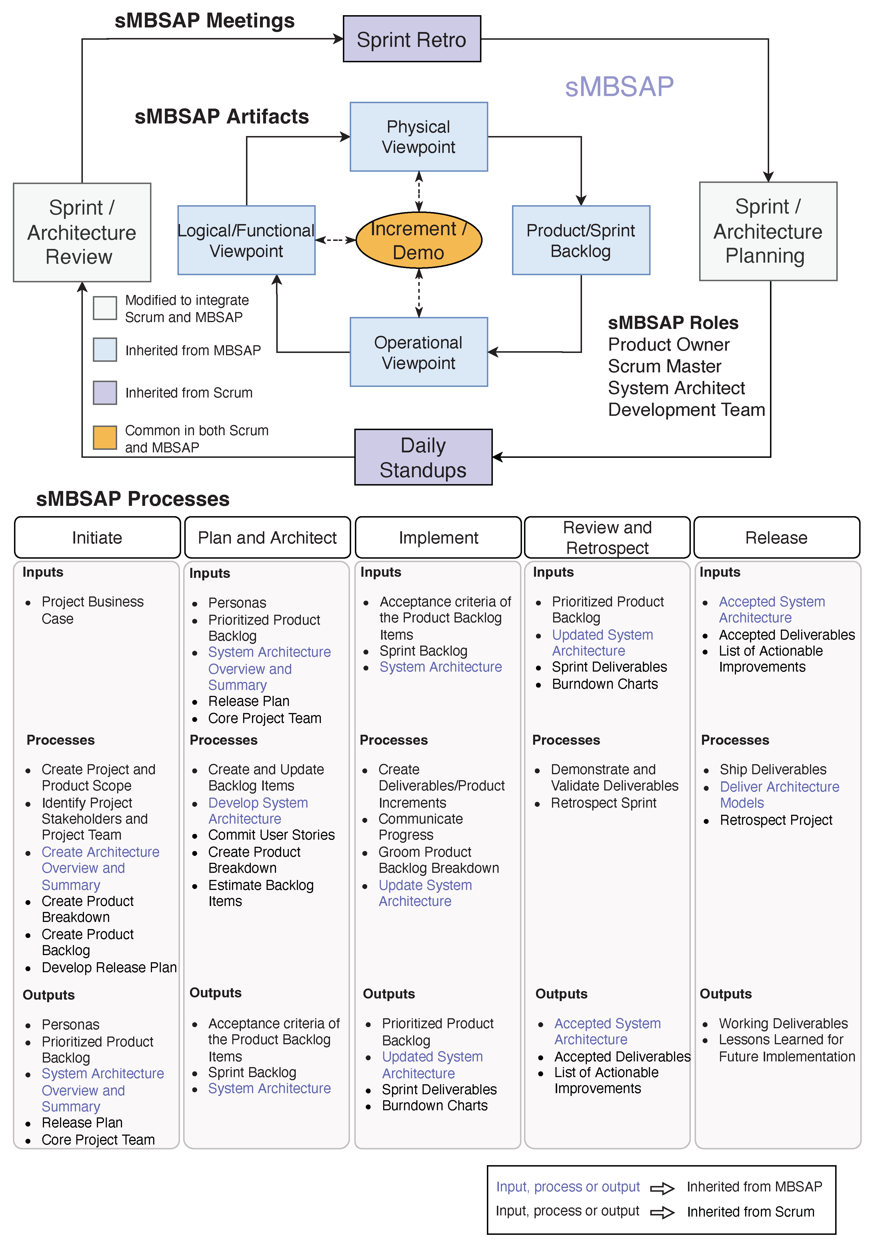
3.2. Overview of the sMBSAP
3.3. Initiate
- Create Project and Product Scope: In this process, the project business case is reviewed to create a Project Scope Statement and subsequent Product Scope. The Product Owner is typically identified at this stage of the project.
- Identify Project Stakeholders and Project Team: In this process, the four project roles are identified, which include the Product Owner, Scrum Master, System Architect, and Product Development Team. Other project stakeholders are also identified during this process.
- Create Architecture Overview and Summary: In this process, an Architecture Overview that provides the following architecture-related information is created: the architecture’s scope, purpose, and perspective, contextual information, the role of the System Architect, and the timeline of the architecture’s development. The Architecture Overview acts as a contract between stakeholders and the System Architect based on establishing bilateral commitments and understanding of the role of the architecture effort within the overall project effort [13]. The main customer for the architecture artifacts is the Product Development Team; accordingly, the System Architect must explain the value and contribution of the architecture process. The System Architect should also expect organizational resistance and lack of support among software developers, especially those who are used to writing code with very little or no documentation as input. In this process, the System Architect decides which MBSE tool they will use throughout the project.
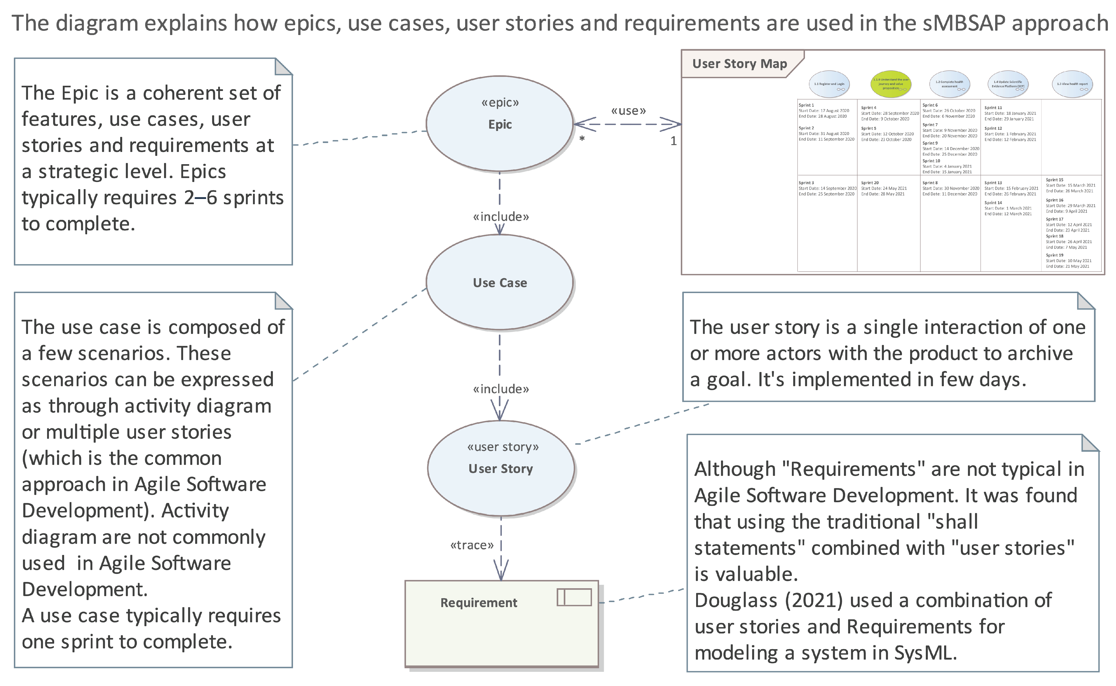
- Create Product Breakdown: In this process, the Project Scope Statement and Product Scope are used as the basis for breaking the product down into Epics, Use Cases, User Stories, and Requirements, as shown in Figure 5. The Product Breakdown is an iterative process that occurs first during the Initiate phase and is further refined through meetings between the project team and key stakeholders in subsequent phases as needed. In the sMBSAP approach, Epics are modeled as stereotyped Use Cases [14] and are decomposed to (lower-level) Use Cases, which are, in turn, decomposed into User Stories, which are broken down into Requirements. This taxonomy is shown in Figure 5.
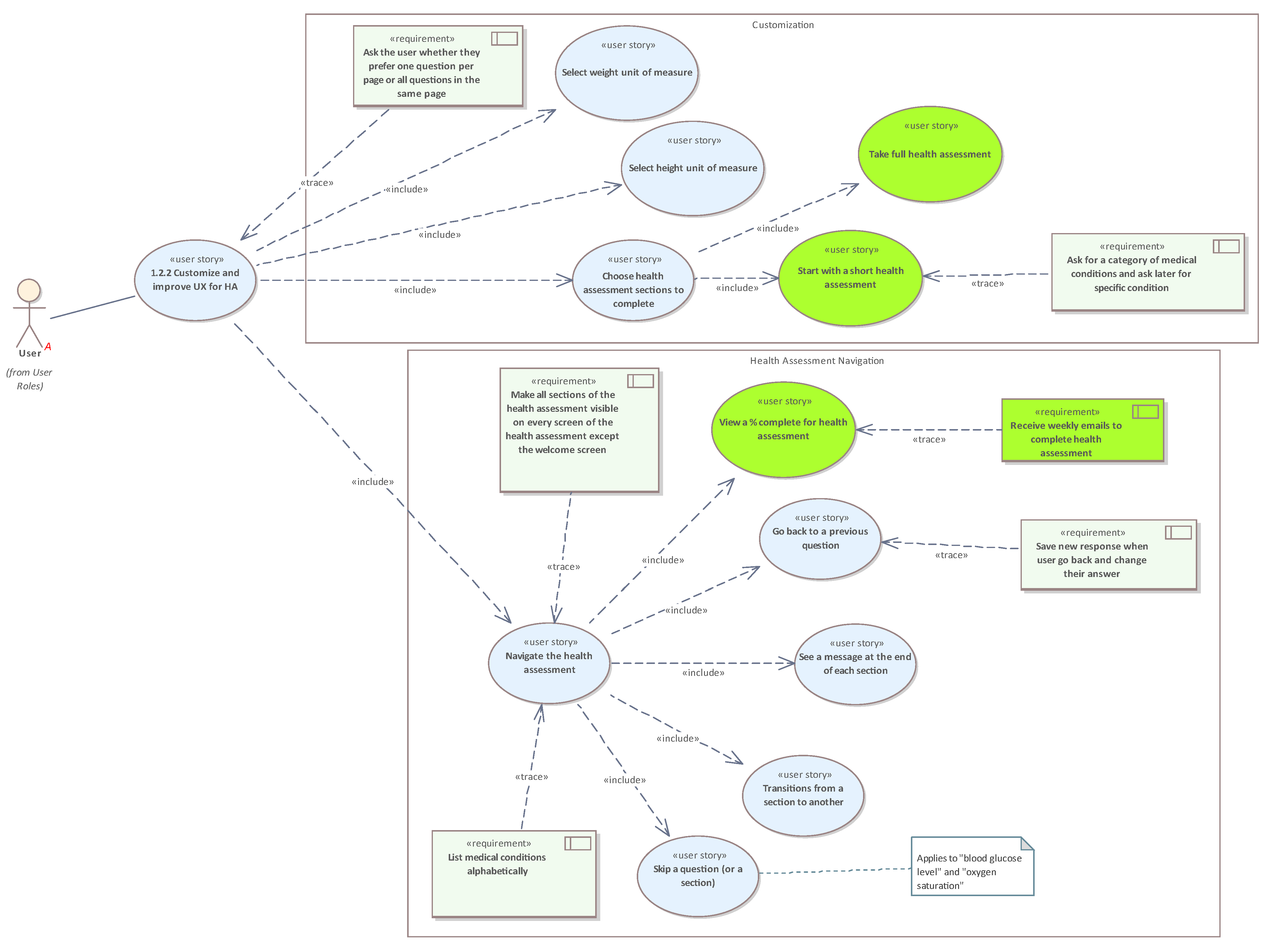
- Create Product Backlog: In this process, User Stories, Requirements, and other tasks are added to the Product Backlog. These items are referred to as Product Backlog Items (PBIs). It is important to note that a project team may choose to use only User Stories (commonly used in Scrum) or both User Stories and Requirements (Requirements are commonly used in MBSE and systems engineering). The PBIs will be progressively refined, elaborated, and later prioritized. The acceptance criteria are also established at this point and will be further elaborated. The Product Backlog is developed and maintained by using a Requirement management tool or Agile development tool, such as Clickup [36]. Alternatively (or in addition), User Stories and Requirements may be visually captured in the model, as shown in Figure 6, which illustrates User Stories and Requirements that are modeled as stereotyped Use Cases, and Requirements are traced to User Stories. This allows a User Story to be described and to its connection to a persona to be shown. In this Use Case diagram, the System Architect wants to capture the interaction of the “User” with the “Health Assessment” module of the system and communicate it with the Product Development Team. The System Architect explains the “User” behavior through a combination of User Stories and Requirements. At the beginning of the “Health Assessment”, the system displays a series of messages to the “User” to allow them to customize their “Health Assessment” experience. The “User” will specifically be asked to select whether they would like to receive one question per page, to select the weight and height unit of measure, to select which health assessment sections to complete, and whether the “User” prefers to focus on a specific category of medical conditions. The “User” will then start navigating the “Health Assessment” sections. The “User” will have the ability to transition from one section to the other. They can also skip questions and come back to them later. The system will display a message at the end of each section to transition the “User” from one section to the other. During the navigation, the “User” can see their progress in terms of the percentage of completion. If the “User” does not complete the “Health Assessment”, the system will send weekly emails reminding the “User” to complete the “Health Assessment”.
- Develop Release Plan: In this process, the product team develops a Release Plan, which is basically a phased deployment timeline that can be shared with the project’s stakeholders. The length of each sprint is usually decided in this process. Some Scrum practitioners develop a Product Roadmap that is more strategic and high-level and a Release Plan that is more tactical and detailed.
3.4. Plan and Architect
- Create and Update Backlog Items: In this process, PBIs (User Stories, Requirements, and tasks) and their related acceptance criteria are created or updated and incorporated into the Product Backlog. User Stories are designed to ensure that the project Requirements are clearly defined and can be entirely understood by all stakeholders. When a User story is committed, it can be broken down into specific tasks (or Requirements and tasks). Agile development tools can show the task list beneath the relevant User Story.
- Develop System Architecture: In this process, the System Architect progressively develops the system architecture. The system architecture is developed in lockstep with the User Stories. Both are used by the Product Development Team to execute the development work. The three main viewpoints progressively developed during this process are:
- -
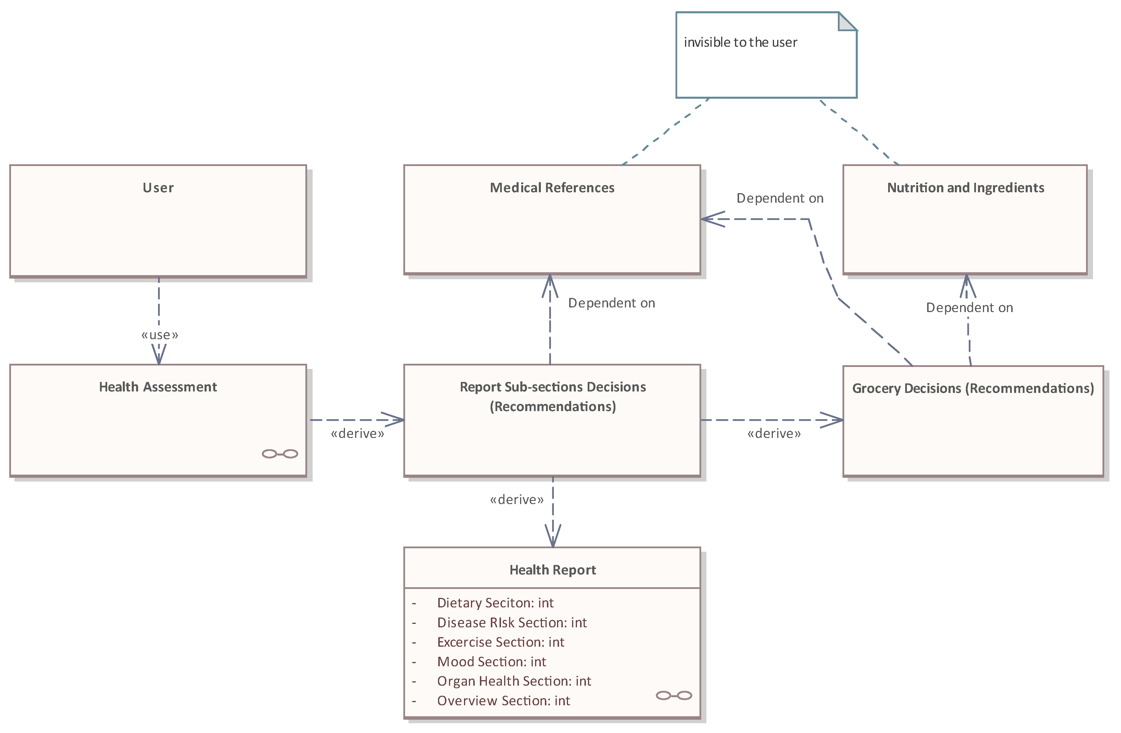
- Operational Viewpoint (OV): The first progression is concerned with translating the Project Scope Statement, Product Scope, and PBIs (in any form that they are expressed) into an architectural model known as an Operational Viewpoint (OV). This mapping is achieved with Use Cases and other object-oriented constructs. Several researchers, such as Lattanze [55], stressed the importance of starting with a high-level view of the architecture before progressing to a more detailed design. The high-level view of the architecture is the primary purpose of the OV. The OV also defines the system’s boundary and context. It also creates top-level partitioning (Domains), primary behaviors (Use Cases), and primary data content. With the aid of the model, the System Architect maps User Stories to Domains and Use Cases. The data model developed in this first progression is called “Conceptual Data Model (CDM)”. This is the most abstract type of data model. Platform-specific information, such as data types, sequences, procedures, and triggers, are not included in the CDM. Because of its simplicity, it is useful for communicating ideas among different stakeholders. Data models can be developed with a number of notations, such as Information Engineering, IDEF1X, UML data modeling, and Entity Relationship notation.The conceptual UML-based data model developed for the health tech system is shown in Figure 7. At this stage, the System Architect wants to capture and communicate the types of data (or “Entities”) that the health tech system needs with the Product Development Team. These entities include the “User”, “Health Assessment”, “Report Subsections Decisions”, “Medical Reference”, and others. In addition to Entities, the CDM also captures the Relationships, i.e., how an Entity connects to other Entities. In the case of the health tech system, the “User” takes the “Health Assessment”. Based on the results of the “Health Assessment”, the “Report Subsections Decisions” will be displayed to the “User” and form the basis of the “Health Report”. The “Report Subsections Decisions” rely on the “Medical Reference” for communicating the recommendations to the “User”. The “Grocery Recommendations” are derived from “Report Subsections Decisions” and depend on both the “Nutrition and Ingredients” and “Medical Reference”. As noted on the CDM, both “Nutrition and Ingredients” and “Medical Reference” are not exposed to the “User”.
- -
- Functional/Logical Viewpoint (LV): The next progression transforms the OV into the Logical/Functional Viewpoint (LV). This is where the design begins using UML class diagrams to define the details of system elements, functions, and data. The LV is a progressive elaboration on the perspectives of the OV and is molded mainly by decomposing Domains and Use Cases to develop structural and behavioral diagrams. The functional service specifications are developed and allocated to logical components and interfaces. The architectural layering is defined. The LV represents a functional definition of the technology- and product-agnostic system. The data model developed in this architecture iteration is called a “Logical Data Model (LDM)”. The LDM defines the detailed Structure of a system’s data elements and the relationships between them. It elaborates on the CDM introduced during the OV progression, but without going to the level of specifying the Database Management System (DBMS) that will be used. LDM forms the basis of the “Physical Data Model (PDM)”. This model is commonly developed by using the UML Data Modeling notation. The logical UML-based data model developed for the health tech system is shown in Figure 8. As shown in Figure 8, the data elements “Medical References” and “Nutrition and Ingredients” contain UML attributes; the names and generic data types remain platform-independent. Platform-specific data types and other metadata that relate to a specific DBMS implementation are defined by the PDM.
- -
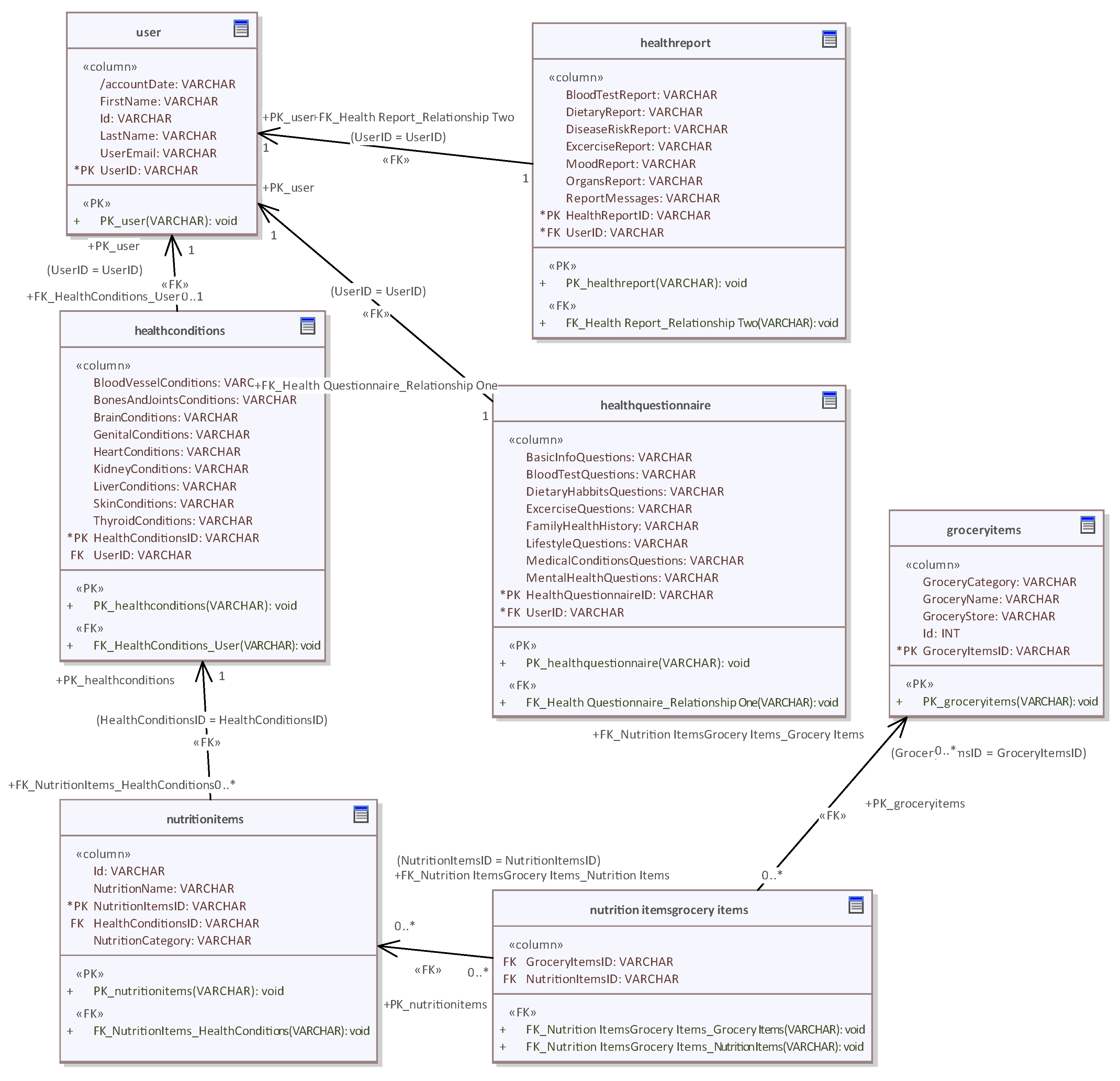
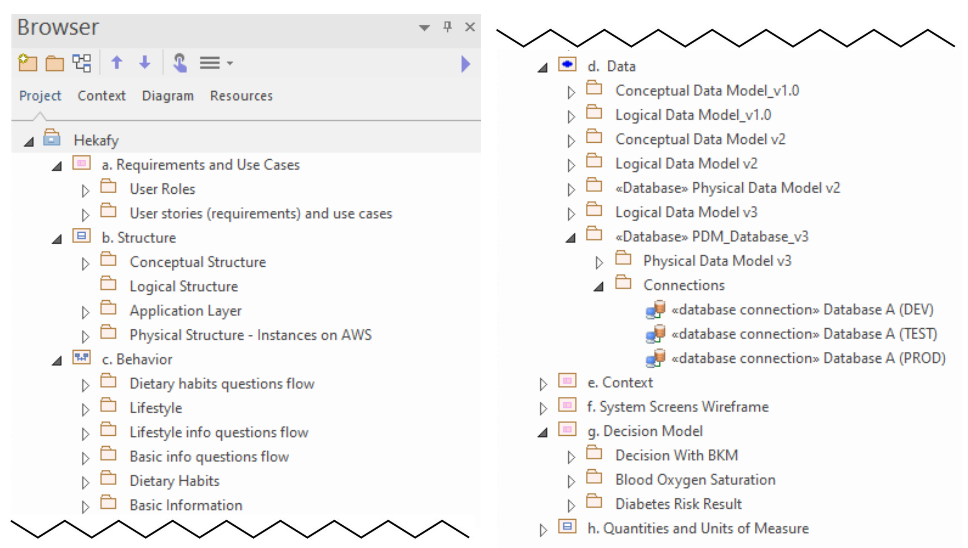
- Physical Viewpoint (PV): The architecture modeling is completed by progressing from the LV to the Physical Viewpoint (PV). The PV is the basis for the actual implementation of the full system or an increment of the system. To clarify the relationship between the LV and the PV, the former defines what is to be built, and the latter defines how it will be realized [13]. Accordingly, this architecture iteration focuses on products and standards whose selection is paramount to reaching a physical design. The data model developed during the PV is called a “Physical Data Model (PDM)”. A PDM graphically represents the Structure of data as implemented by a relational database schema. The ability to automatically generate the database schema from a PDM is a significant advantage of PDMs, in addition to presenting a visual abstraction of the database structure. This is made feasible by the amount of metadata that a PDM captures and its close alignment with aspects of the database schema, such as database tables, columns, primary keys, and foreign keys. The UML-based PDM developed for the health tech system is shown in Figure 9. Each table is represented by a UML Class; table columns, primary keys, and foreign keys are modeled by using UML attributes and operations. The DBMS type used in the system is PostgreSQL.It is important to note that each viewpoint is represented with several perspectives (within the viewpoints); the perspectives are largely derived from the fundamental elements of the architecture and the needs of the project. The proposed perspectives for the sMBSAP are the Structure, Behavior, Data, and Requirements, as shown in Figure 10. The importance of an adequate model Structure in achieving the full benefits of MBSE should be emphasized [13]. One way to group the content of each viewpoint into a set of perspectives that create a logical and easily searchable content framework is shown in Figure 11.
- Commit User Stories: In this process, the project team commits to delivering the approved User Stories for a sprint. The committed User Stories are added to the Sprint Backlog. During the Sprint/Architecture Planning, the Scrum team may add further details to the PBIs.
- Estimate Backlog Items: In this process, the project team, supported by the System Architect, estimates the PBIs and estimates the effort required to develop the functionality described in each PBI.
3.5. Implement
- Create Deliverables/Product Increments: In this process, the project team works on the items in the Sprint Backlog to create sprint deliverables. The project team’s progress, measured in completed story points, is captured in an Agile development tool. Planned versus actual story points are captured in the tool, in addition to marking an item as “done” when it is completed. The collected data are plotted on burnup charts and velocity fluctuation charts to allow the Scrum Master to monitor the project’s health and make course corrections when needed.It is important to note that creating deliverables/Product Increments may include activities such as project management, software engineering, continuous integration and testing, system configuration management, security, and other aspects. The sMBSAP is similar to the MBSAP in that the design modeled in the PV is built up in a prototype and goes through continuous integration and testing to assess its suitability against the required capabilities that are being addressed.
- Communicate Progress: In this process, the project team members update each other on their individual progress and any barriers that they may be facing. These updates occur through a short daily 15 min meeting, referred to as a Standup Meeting. The System Architect participates in these meetings and addresses any issues that the Product Development Team faces in relation to the system architecture.
- Groom Product Backlog: In this process, the prioritized PBIs are continuously updated and refined. A backlog grooming meeting is conducted to discuss any changes or updates to the backlog.
- Update System Architecture: In this process, the system architecture models are continuously updated and refined based on the progress and feedback from the project team. The results of the architecture changes or updates are discussed during the Sprint/Architecture Review.
3.6. Review and Retrospect
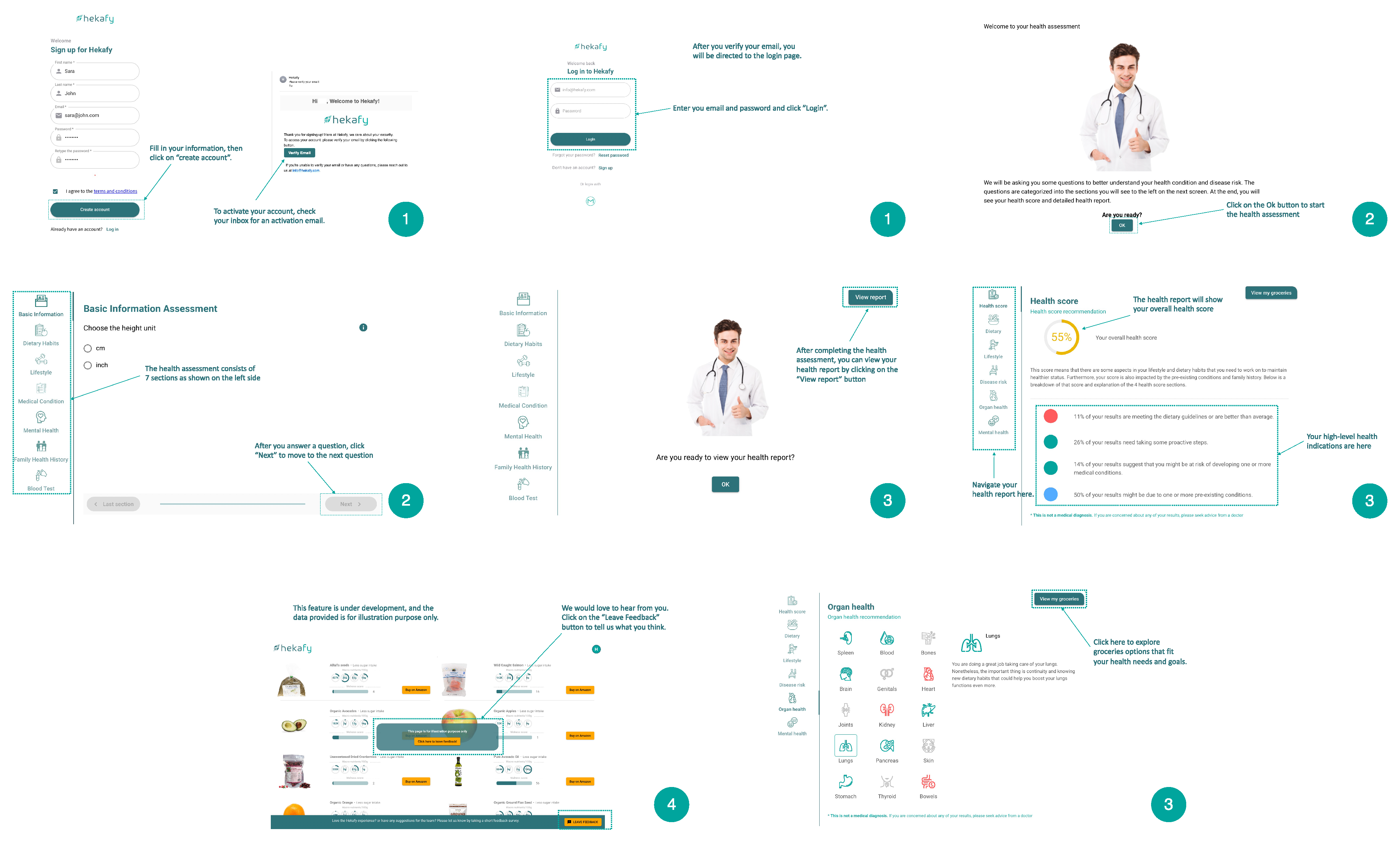
- Demonstrate and Validate Deliverables: In this process, the System Architect presents the updated system architecture to the project stakeholders. The project team then demonstrates the sprint deliverables that match the models to the stakeholders. These presentations and demos occur in a Sprint/Architecture Review meeting. This meeting aims to gain the acceptance of the delivered PBIs from the Product Owner.Screenshots from the health tech system product demo are shown in Figure 12. The product demo shows the four key steps in the “User” journey at a high level. In step 1, the “User” completes the registration process by entering their first name, last name, and email address, creating a password, and confirming it. After the “User” confirms their email address, they are redirected to the login page. In step 2, the “User” will be introduced to the “Health Assessment” and start completing its various sections. At the end of the “Health Assessment”, the “User” will proceed to the third step, which is reviewing their “Health Report”. Finally, in the fourth step, the “User” will receive the grocery items recommended for their health profile.
- Retrospect Sprint: In this process, the project team meets in a Sprint Retro meeting to discuss the lessons learned from the previous sprint. This information is recorded and should be used in future sprints. As a result of this meeting, some actions to improve performance or to make course corrections may be decided upon.
3.7. Release
- Ship Deliverables and Architecture Models: In this process, approved and accepted deliverables are handed over to the concerned stakeholders. A formal transition document should be drafted and signed by the concerned stakeholders denoting the successful completion of the agreed-upon shippable part of the product. The architecture models are also handed over to the concerned stakeholders. The combined artifacts developed for the health tech system are shown in Figure 13.
- Retrospect Project: This is the final step in the project, in which the project team and stakeholders meet to identify and document the lessons learned for future implementation. This meeting is called the Project Retrospective meeting (or Retro).
4. Discussion
- The System Architect works closely, not in a silo, with the Product Development Team to (1) co-customize the MBSE tool at the beginning of the project to align with the needs of the project and the Product Development Team. The customization exercise is used as an MBSE infusion opportunity. In an MBSE-driven project, the Product Development Team is the first customer of the system architecture, and the Maintenance and Operations team is the end user, as they leverage the system architecture in operating software applications, monitoring system performance, making defect repairs, etc. The System Architect would need to work closely with different business and technical stakeholders from the customer organization to ensure that the model perspective and viewpoints are customized to fit their needs and the organization’s standards.(2) It is also necessary to engage and educate the Product Development Team about the basic concepts and processes of the architecture and (3) to empower and support the Product Development Team Members (owners of core components of the system) to define discipline-specific MBSE methods. For example, a frontend developer develops a wireframe for the “Health report summary” including the screen elements, such as the following: buttons—“View my groceries”; dashboard indicators and messages—“Health score” and “Summary health report”; navigation sections—“Dietary”, “Lifestyle”, “Disease risk”, “Organ health”, and “Mental health”; finally, a scroll bar. The System Architect works closely with the frontend developer to ensure that every screen element is aligned with and mapped to Requirements or User Stories, as shown in Figure 15. The System Architect adds the relevant Requirements and User Stories to the wireframe. Throughout the process, the wireframe is refined and updated to reflect the intended use of each screen. The outcome of this collaborative effort is a model-based wireframe (an artifact unique to the sMBSAP).
- Selecting an MBSE tool with (1) built-in methodologies that support the transformation of current systems engineering practices into model-centric engineering practices and (2) built-in models that support specific Use Cases would help create a faster first iteration of the model. This fast turnaround increases the engagement of the Product Development Team and contributes to changing the perception that architecture modeling slows down the development process. For example, some MBSE tools have built-in Gantt charts, which can automatically display the schedule for sprints, and built-in and customizable dashboards that can be used to show the progress of a sprint. Moreover, the Product Owner, Scrum Master, and Team Member roles can all be supported, needless to say, by the role of the System Architect. Selecting and customizing the right MBSE tool will provide a cohesive collaboration and Requirement management platform.
- The sMBSAP enables the System Architect to use Agile terminologies that the Product Development Team understands. Implementing Agile concepts such as sprints, Product Backlog, Epics, and User Stories conveys a sense of familiarity to the Product Development Team, even if these concepts are implemented within the context of an MBSE and architecture-driven environment.
- The sMBSAP leverages the MBSE tool to combine the UML-based formal description of the system with non-formal models that fit the needs of the Product Development Team. Combining formal and non-formal modeling aids in addressing the usability challenge, as it gives more freedom to the Product Development Team. The value of this combination is to instill in the Product Development Team the concept of keeping all artifacts in one model. For example, wireframes are valuable visuals that are widely used in Agile software development. Integrating the non-UML-based wireframes in the sMBSAP approach could increase the engagement of the Product Development Team and the adoption of the sMBSAP.
- The architecture effort progresses one sprint at a time. After the System Architect prepares the high-level end-to-end OV of the system, they focus only on the Requirements and the Structural, Behavioral, and Data perspectives of one sprint at a time. In that sprint, the OV is further elaborated into an LV, which will be progressively elaborated in future sprints. This approach could potentially be a step toward addressing the disconnect between how the system is conceptualized and how it is described, since the description is progressively elaborated over several weeks or months.
- The Requirements and User Stories will be traced to the various perspectives of the system model throughout the subsequent iterations or viewpoints. In Use Case diagrams, Requirements are traced to User Stories that are modeled using a stereotyped Use Case. Requirements can then be shown on other models to trace the implementation of Requirements and User Stories (a Requirement or User Story is created once and used multiple times across the model). This approach simplifies the traceability process and bypasses the need to develop and maintain a document-based Requirement Traceability Matrix. Model-based Requirement Traceability could be a meeting ground between those who devalue Traceability and those who want to align with procurement/reporting practices.
- The iterative benefits of Agile combined with an integrated model of artifacts, as proposed in the sMBSAP, could be a practical happy medium between light documentation enthusiasts and those who value heavy documentation. The centralized management of artifacts makes the sMBSAP approach suitable for projects that value a working product and, at the same time, are keen to have more manageable, accessible, and retrievable documentation via a system architecture model.
5. Conclusions and Future Work
Author Contributions
Funding
Data Availability Statement
Acknowledgments
Conflicts of Interest
Abbreviations
| ASD | Adaptive Software Development |
| AUP | Agile Unified Process |
| CDM | Conceptual Data Model |
| DBSE | Document-Based Systems Engineering |
| DoDAF | Department of Defense Architecture Framework |
| DSDM | Dynamic Systems Development Method |
| FDD | Feature-Driven Development |
| FEAF | Federal Enterprise Architecture Framework |
| LDM | Logical/Functional Data Model |
| LV | Logical Viewpoint |
| MAGIC | Munich Agile MBSE Concept |
| MBSAP | Model-Based System Architecture Process |
| MDSD | Model-Driven Systems Development |
| MBSE | Model-based Software Engineering |
| NIST | National Institute of Standards and Technology |
| OPM | Object-Process Methodology (Dori) |
| OOSEM | Object-Oriented Systems Engineering Method (INCOSE) |
| OV | Operational Viewpoint |
| PBI | Product Backlog Items |
| PDM | Physical Data Model |
| PV | Physical Viewpoint |
| RAD | Rapid Application Development |
| RUP | Rational Unified Process |
| RUP SE | Rational Unified Process for Systems Engineering (IBM) |
| SAFe | Scaled Agile Framework |
| SDLC | Software Development Life Cycle |
| SA | State Analysis (JPL) |
| SE | Systems Engineering |
| sMBSAP | Scrum Model-Based System Architecture Process |
| TOGAF | The Open Group Architecture Framework |
| UML | Unified Modeling Language |
| XP | Extreme Programming |
References
- Hooshmand, Y.; Adamenko, D.; Kunnen, S.; Köhler, P. An approach for holistic model-based engineering of industrial plants. In Proceedings of the International Conference on Engineering Design, Vancouver, BC, Canada, 21–25 August 2017; Volume 3, pp. 101–110. [Google Scholar]
- Friedenthal, S.; Moore, A.; Steiner, R. A Practical Guide to SysML: The Systems Modeling Language, 3rd ed.; Morgan Kaufmann: Burlington, MA, USA, 2015. [Google Scholar] [CrossRef]
- Basha, N.M.J.; Moiz, S.A.; Rizwanullah, M. Model based software development: Issues & challenges. Int. J. Comput. Sci. Inform. 2013, 3, 84–88. [Google Scholar] [CrossRef]
- Call, D.R.; Herber, D.R. Applicability of the diffusion of innovation theory to accelerate model-based systems engineering adoption. Syst. Eng. 2022, 25, 574–583. [Google Scholar] [CrossRef]
- Cao, L.; Ramesh, B. Agile software development: Ad hoc practices or sound principles? IT Prof. 2007, 9, 41–47. [Google Scholar] [CrossRef]
- Altahtooh, U.A.; Emsley, M.W. Is a challenged project one of the final outcomes for an IT project? In Proceedings of the Hawaii International Conference on System Sciences, Waikoloa, HI, USA, 6–9 January 2014; pp. 4296–4304. [Google Scholar] [CrossRef]
- Muganda Ochara, N.; Kandiri, J.; Johnson, R. Influence processes of implementation effectiveness in challenged information technology projects in Africa. Inf. Technol. People 2014, 27, 318–340. [Google Scholar] [CrossRef]
- Yeo, K.T. Critical failure factors in information system projects. Int. J. Proj. Manag. 2002, 20, 241–246. [Google Scholar] [CrossRef]
- Turner, R. Toward Agile systems engineering processes. Crosstalk J. Def. Softw. Eng. 2007, 20, 11–15. [Google Scholar]
- Salehi, V.; Wang, S. Munich Agile MBSE Concept (MAGIC). In Proceedings of the Design Society: International Conference on Engineering Design, Delft, The Netherlands, 5–8 August 2019; Volume 1, pp. 3701–3710. [Google Scholar] [CrossRef]
- Riesener, M.; Doelle, C.; Perau, S.; Lossie, P.; Schuh, G. Methodology for iterative system modeling in Agile product development. Procedia CIRP 2021, 100, 439–444. [Google Scholar] [CrossRef]
- Bott, M.; Mesmer, B. An analysis of theories supporting Agile scrum and the use of scrum in systems engineering. Eng. Manag. J. 2020, 32, 76–85. [Google Scholar] [CrossRef]
- Borky, J.M.; Bradley, T.H. Effective Model-Based Systems Engineering; Springer: Berlin/Heidelberg, Germany, 2019. [Google Scholar] [CrossRef]
- Douglass, B.P. Agile Model-Based Systems Engineering Cookbook; Packt: Birmingham, UK, 2021. [Google Scholar]
- Bouillon, E.; Güldali, B.; Herrmann, A.; Keuler, T.; Moldt, D.; Riebisch, M. Leichtgewichtige Traceability im agilen Entwicklungsprozess am Beispiel von Scrum. Softwaretechnik-Trends 2013, 33, 29–30. [Google Scholar] [CrossRef]
- Lethbridge, T.; Singer, J.; Forward, A. How software engineers use documentation: The state of the practice. IEEE Softw. 2003, 20, 35–39. [Google Scholar] [CrossRef]
- Voigt, S.; Hüttemann, D.; Gohr, A.; Große, M. Agile Documentation Tool Concept. In Developments and Advances in Intelligent Systems and Applications; Springer: Berlin/Heidelberg, Germany, 2018; pp. 67–79. [Google Scholar]
- Ruparelia, N.B. Software development lifecycle models. ACM SIGSOFT Softw. Eng. Notes 2010, 35, 8–13. [Google Scholar] [CrossRef]
- Rather, M.A.; Bhatnagar, M.V. A comparative study of software development life cycle models. Int. J. Appl. Innov. Eng. Manag. 2015, 4, 23–29. [Google Scholar]
- Tsai, B.Y.; Stobart, S.; Parrington, N.; Thompson, B. Iterative design and testing within the software development life cycle. Softw. Qual. J. 1997, 6, 295–310. [Google Scholar] [CrossRef]
- Kossiakoff, A.; Biemer, S.M.; Seymour, S.J.; Flanigan, D.A. Systems Engineering Principles and Practice; John Wiley & Sons: Hoboken, NJ, USA, 2020. [Google Scholar]
- Dora, S.K.; Dubey, P. Software development life cycle (SDLC) analytical comparison and survey on traditional and Agile methodology. Natl. Mon. Ref. J. Res. Sci. Technol. 2013, 2, 22–30. [Google Scholar]
- Schmidt, C. Agile Software Development Teams; Progress in IS; Springer: Berlin/Heidelberg, Germany, 2015. [Google Scholar] [CrossRef]
- Khong, L.; Yu Beng, L.; Yip, T.; Soofun, T. Software development life cycle AGILE vs traditional approaches. In Proceedings of the International Conference on Information and Network Technology, Chennai, India, 28–29 April 2012; Volume 37, pp. 162–167. [Google Scholar]
- Vijayasarathy, L.R.; Turk, D. Agile software development: A survey of early adopters. J. Inf. Technol. Manag. 2008, XIX, 1–8. [Google Scholar]
- U.S. Government Accountability Office. Agile Assessment Guide: Best Practices for Agile Adoption and Implementation; Technical Report GAO-20-590G; U.S. Government Accountability Office: Washington, DC, USA, 2015.
- Anand, R.V.; Dinakaran, M. Issues in scrum Agile development principles and practices in software development. Indian J. Sci. Technol. 2015, 8, 1–5. [Google Scholar] [CrossRef]
- DIGITAL.AI. 16th State of Agile Report. 2022. Available online: https://info.digital.ai/rs/981-LQX-968/images/AR-SA-2022-16th-Annual-State-Of-Agile-Report.pdf (accessed on 14 April 2022).
- Schwaber, K. Agile Project Management with Scrum; Microsoft Press: Unterschleissheim, Germany, 2004. [Google Scholar]
- Satpathy, T. A Guide to the Scrum Body of Knowledge (SBOK™ Guide), 3rd ed.; SCRUMstudy: Avondale, AZ, USA, 2016. [Google Scholar]
- Akif, R.; Majeed, H. Issues and challenges in scrum implementation. Int. J. Sci. Eng. Res. 2012, 3, 1–4. [Google Scholar]
- Buffardi, K.; Robb, C.; Rahn, D. Learning agile with tech startup software engineering projects. In Proceedings of the ACM Conference on Innovation and Technology in Computer Science Education, Bologna, Italy, 3–5 July 2017; pp. 28–33. [Google Scholar] [CrossRef]
- Ghezzi, A.; Cavallo, A. Agile business model innovation in digital entrepreneurship: Lean startup approaches. J. Bus. Res. 2020, 110, 519–537. [Google Scholar] [CrossRef]
- Kuchta, D. Combination of the earned value method and the Agile approach—A case study of a production system implementation. In Intelligent Systems in Production Engineering and Maintenance; Springer: Berlin/Heidelberg, Germany, 2019; pp. 87–96. [Google Scholar] [CrossRef]
- Atlassian. Jira|Issue & Project Tracking Software|Atlassian. 2019. Available online: https://www.atlassian.com/software/jira (accessed on 14 April 2022).
- ClickUp™. Available online: https://www.clickup.com.html (accessed on 28 February 2023).
- Brambilla, M.; Cabot, J.; Wimmer, M. Model-Driven Software Engineering in Practice; Springer: Cham, Switzerland, 2017. [Google Scholar] [CrossRef]
- Bonnet, S.; Voirin, J.L.; Normand, V.; Exertier, D. Implementing the MBSE cultural change: Organization, coaching andlessons learned. In Proceedings of the INCOSE International Symposium, Seattle, WA, USA, 13–16 July 2015; Volume 25, pp. 508–523. [Google Scholar] [CrossRef]
- Walden, D.D.; Roedler, G.J.; Forsberg, K. INCOSE systems engineering handbook version 4: Updating the reference for practitioners. In Proceedings of the INCOSE International Symposium, Seattle, WA, USA, 13–16 July 2015; Volume 25, pp. 678–686. [Google Scholar] [CrossRef]
- Estefan, J.A. Survey of Model-Based Systems Engineering (MBSE) Methodologies; Technical report; INCOSE MBSE Initiative: San Diego, CA, USA, 2008. [Google Scholar]
- Zimmerman, P. A review of model-based systems engineering practices and recommendations for future directions in the department of defense. In Proceedings of the Systems Engineering in the Washington Metropolitan Area Conference, Chantilly, VA, USA, 3 April 2014. [Google Scholar]
- Wang, L.; Izygon, M.; Okon, S.; Wagner, H.; Garner, L. Effort to accelerate MBSE adoption and usage at JSC. In Proceedings of the AIAA SPACE, Long Beach, CA, USA, 13–16 September 2016. [Google Scholar] [CrossRef]
- Young, K.G. Defense space application of MBSE-closing the culture chasms. In Proceedings of the AIAA SPACE Conference and Exposition, Pasadena, CA, USA, 31 August–2 September 2015. [Google Scholar] [CrossRef]
- Noguchi, R.A. A roadmap for advancing the state of the practice of model based systems engineering for government acquisition. In Proceedings of the INCOSE International Symposium, Orlando, FL, USA, 20–25 July 2019; Volume 29, pp. 678–690. [Google Scholar] [CrossRef]
- Kim, S.Y.; Wagner, D.; Jimenez, A. Challenges in applying model-based systems engineering: Human-centered design perspective. In Proceedings of the INCOSE Human-Systems Integration Conference, Biarritz, France, 11–13 September 2019. [Google Scholar]
- Hadar, I.; Sherman, S.; Hadar, E.; Harrison, J.J. Less is more: Architecture documentation for agile development. In Proceedings of the International Workshop on Cooperative and Human Aspects of Software Engineering, San Francisco, CA, USA, 25 May 2013; pp. 121–124. [Google Scholar] [CrossRef]
- Manifesto for Agile Software Development. Available online: http://agilemanifesto.org (accessed on 27 March 2023).
- Stettina, C.J.; Heijstek, W. Necessary and neglected? An empirical study of internal documentation in agile software development teams. In Proceedings of the ACM International Conference on Design of Communication, Pisa, Italy, 3–5 October 2011; pp. 159–166. [Google Scholar] [CrossRef]
- Pasuksmit, J.; Thongtanunam, P.; Karunasekera, S. Towards just-enough documentation for agile effort estimation: What information should be documented? In Proceedings of the IEEE International Conference on Software Maintenance and Evolution, Luxembourg, 27 September–1 October 2021; pp. 114–125. [Google Scholar] [CrossRef]
- Prause, C.R.; Durdik, Z. Architectural design and documentation: Waste in agile development? In Proceedings of the International Conference on Software and System Process, Zurich, Switzerland, 2–3 June 2012; pp. 130–134. [Google Scholar] [CrossRef]
- Rubin, E.; Rubin, H. Supporting agile software development through active documentation. Requir. Eng. 2011, 16, 117–132. [Google Scholar] [CrossRef]
- Selic, B. Agile documentation, anyone? IEEE Softw. 2009, 26, 11–12. [Google Scholar] [CrossRef]
- Slack. Available online: https://slack.com (accessed on 28 February 2023).
- Sparx Systems. Enterprise Architect 15.2 User Guide. Available online: https://sparxsystems.com/enterprise_architect_user_guide/15.2/ (accessed on 28 February 2023).
- Lattanze, A.J. Architecting Software Intensive Systems: A Practitioners Guide; Auerbach Publications: Boca Raton, FL, USA, 2008. [Google Scholar]


| Role | Gender | Industry Experience | Highest Education Level | Familiarity with System Development |
|---|---|---|---|---|
| System Architect and Scrum Master | Male | 20+ years | MSc | Yes |
| Backend Developer | Male | 15+ years | PhD | Yes |
| Frontend Developer | Male | 15+ years | PhD | Yes |
| Health and Nutrition Scientist | Female | 15+ years | PhD | No |
Disclaimer/Publisher’s Note: The statements, opinions and data contained in all publications are solely those of the individual author(s) and contributor(s) and not of MDPI and/or the editor(s). MDPI and/or the editor(s) disclaim responsibility for any injury to people or property resulting from any ideas, methods, instructions or products referred to in the content. |
© 2023 by the authors. Licensee MDPI, Basel, Switzerland. This article is an open access article distributed under the terms and conditions of the Creative Commons Attribution (CC BY) license (https://creativecommons.org/licenses/by/4.0/).
Share and Cite
Huss, M.; Herber, D.R.; Borky, J.M. An Agile Model-Based Software Engineering Approach Illustrated through the Development of a Health Technology System. Software 2023, 2, 234-257. https://doi.org/10.3390/software2020011
Huss M, Herber DR, Borky JM. An Agile Model-Based Software Engineering Approach Illustrated through the Development of a Health Technology System. Software. 2023; 2(2):234-257. https://doi.org/10.3390/software2020011
Chicago/Turabian StyleHuss, Moe, Daniel R. Herber, and John M. Borky. 2023. "An Agile Model-Based Software Engineering Approach Illustrated through the Development of a Health Technology System" Software 2, no. 2: 234-257. https://doi.org/10.3390/software2020011