Article

BPM2DDD: A Systematic Process for Identifying Domains from Business Processes Models

by
Carlos Eduardo da Silva
1,*,
Eduardo Luiz Gomes
2 and
Soumya Sankar Basu
1
1
Department of Computing, Sheffield Hallam University, Sheffield S1 2NU, UK
2
E-Masters Tecnologia, Natal 59151-600, Brazil
*
Author to whom correspondence should be addressed.
Software 2022, 1(4), 417-449; https://doi.org/10.3390/software1040018
Submission received: 28 July 2022 / Revised: 23 September 2022 / Accepted: 24 September 2022 / Published: 29 September 2022
(This article belongs to the Topic Software Engineering and Applications)

Abstract

:
Domain-driven design is one of the most used approaches for identifying microservice architectures, which should be built around business capabilities. There are a number of documentation with principles and patterns for its application. However, despite its increasing use there is still a lack of systematic approaches for creating the context maps that will be used to design the microservices. This article presents BPM2DDD, a systematic approach for identification of bounded contexts and their relationships based on the analysis of business processes models, which provide a business view of an organisation. We present an example of its application in a real business process, which has also be used to perform a comparative application with external analysts. The technique has been applied to a real project in the department of transport of a Brazilian state capital, and has been incorporated into the software development process employed by them to develop their new system.

1. Introduction

Domain-Driven Design (DDD) is an approach to develop complex systems from the early 2000’s. It consists in a series of design patterns and general guidance on their application, where the implementation is deeply connected to models that represent the main business or domain concepts [1]. DDD has gained a renewed interest with the appearance of microservice architecture (MSA) [2]. Microservices can be currently interpreted as an implementation tactic of a service oriented architecture, where software systems are composed by several small services, each running individually in its own process and communicating with each other through lightweight mechanisms [3].
There is a consensus in the literature (e.g., [3,4,5,6,7]) that microservices should be built and maintained around a specific business capability. However, one of the great challenges of MSA is the decomposition of the system into services properly aligned to the business context [4]. Amiri [6] identifies this challenge as the Microservices Identification Problem. A number of studies explored this problem, for example, systematic literature reviews [8] and interviews and surveys with industry practitioners [9,10], and have identified that “a combination of domain-driven design and business capability is the most used strategy to decompose an application into microservices” [11].
One of the main concepts of DDD is the bounded context. According to Evans & Fowler [1] a “bounded context” is the limited application of a specific domain model. The use of bounded contexts to define structured interfaces around the boundaries of the business domain favours the definition of loosely coupled and highly cohesive services [5], being highly recommended and explored for the definition of microservices. However, the use of DDD is a complex activity in which the results obtained often depends on the level of experience of the development team [12] This is further demonstrated by the existence of approaches to help in the use of incomplete DDD artefacts [2].
One can find a number of documentation with principles, patterns and examples of the use of DDD for identifying MSA (e.g., [1,5,13,14]). However, based on the literature review, there is no defined systematic process that guides the creation of DDD artefacts. In fact, approaches that do mention the design of DDD artefacts do so with references to the general guidance (e.g., [12,15]).
Moreover, one of the ways to properly identify software services taking into account business capabilities is through the business view, which can be done by the analysis of business processes [16]. It is well established that business process models provide system analysts with information that captures realistic business needs, being crucial for the requirements elicitation activity, with noticeable improvement in the quantity and quality of the requirements collected [17,18]. Thus, it is only natural that business process models would be used in conjunction with DDD to improve the requirements gathering and design of software systems. In complex scenarios, business processes can use more than one service, belonging to different areas or business contexts to perform their operations, providing important insights in the modelling of more complex logic, including the interaction between different services [5].
In this context, this article tackles the following research problem: “How to identify domains and build context maps based on knowledge extracted from business process models”.
We present BPM2DDD, an approach for the identification of bounded context and their relationship from business process models. BPM2DDD defines a concrete systematic process to support the definition of DDD context maps. Our approach favours the use of business processes earlier in the development life cycle contributing for a design that is more aligned with business needs of organisations. BPM2DDD has been applied in the context of a real project in a department of transport of a Brazilian state capital. BPM2DDD complements the software development process employed by them, the SPReaD process [19], an instantiation of the mainstream SOA methodology for the development of MSA.
We demonstrate the application of BPM2DDD using a real business process as example. The technique has been applied to other business processes in the institution and the resulting DDD context map was used to develop systems that provides services for the citizens today. We have also performed a comparative application of the technique with external analysts who provided valuable feedback and demonstrated that BPM2DDD can indeed be used to support the creation of DDD artefacts by other people.
The remainder of this article is organised as follow: Section 2 presents a discussion on the background and related work. Section 3 describes the BPM2DDD process, while Section 4 presents an example of its application using a real business process. Section 5 presents an evaluation and discussion of our approach. Finally, Section 6 concludes the article.

2. Background and Related Work

This section presents a brief background on business process management and domain-driven design, followed by a discussion on related work.

2.1. Background on BPM and DDD

Business processes management (BPM) is a discipline that combines knowledge of the areas of information technology (IT) with the science of administration, to support the management and improvement of operational business processes [20,21]. In the IT context, the term is usually associated with workflow management (WFM) software that automates, controls and supports operational processes, while in the business context, the term has a broader scope that encompasses everything from automation, analysis of processes, operations management and work organisation [20].
A process is a set of activities performed by humans or machines in order to achieve one or more results [22]. Within the context of BPM, business processes are treated as assets of the organisation and represent a set of activities that aim to support other organisational processes, achieve business objectives and deliver value to customers, whether internal or external to the organisation [21,22]. Among the activities of BPM is process modelling.
Process modelling concerns the creation of detailed and accurate representations of a business process that already exists or will be proposed [22]. Models serve to communicate different perspectives of a business process and have been used by companies to capture, design, document and analyse their processes, providing a common basis for discussion [21]. There are several types of notations to represent these process models, such as, Petri nets, UML and EPC (Event-driven Process Chain) [20]. Among them is the BPMN (Business Process Model and Notation) [23], selected in this work as the standard notation for representing business process models, since they can be understood by different target audiences, including systems analysts and customers.
BPMN has several elements that allow the creation of models of the most varied types of processes. Even complex processes can be represented initially using few BPMN elements. These models can be iteratively improved over time. Among the elements that make up the BPMN notation, one can find: pools, lanes, flows, activities, sub-processes, events, data objects, gateways, among others. This is the notation used to describe our approach and an example of a real business process using BPMN is presented in Section 4. The following is a brief explanation of these elements, as defined by [23] and represented in the Figure 1:
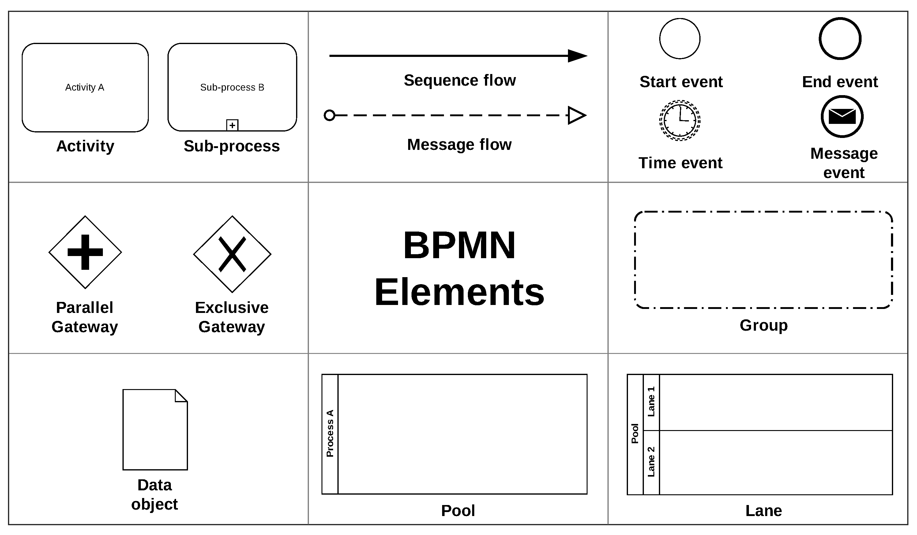
  • Events: Represents something that happens during the course of a process. Events usually have a cause (trigger) or an outcome. Represented by a circle, there are three basic types of events, namely: start event, intermediate event and end event.
  • Activities: Represents a job to be performed within the process flow. An activity can be a task or a sub-process (set of tasks).
  • Gateways: Represents a divergence or a convergence of sequence flows in a process. A gateway determines a branching, forking, merging and joining of paths.
  • Sequence flows: Demonstrates the order in which activities are performed within a process.
  • Message flow: Demonstrates communication between two process participants (represented by two separate pools in a collaboration diagram).
  • Pool: Represents a participant in a collaboration. It acts as a container partitioning a set of activities from other pools.
  • Lane: Represents a sub-partition of of a pool and serves to organise and categorise activities.
  • Messages: Represents the content of a communication between two participants.
  • Data objects: Represent a set or collection of information. Data objects can serve as input or be produced in process activities.
  • Groups: Represents a grouping of elements within the same category. Groups are typically used for documentation and analysis purposes and do not change the flow of the process.
Domain-Driven Design (DDD) is an approach to develop complex systems, where the implementation is deeply connected to models that represent the main business or domain concepts [1]. One of the main concepts of DDD is the bounded contexts. According to Evans & Fowler [1] a “bounded context” is the limited application of a specific domain model, that is, a bounded context is a model that represents part of a larger domain. In this way, a large data model can be divided into small contexts, allowing business objects to be modelled based on specific needs. Newman [5] indicates that the use of bounded contexts to define structured interfaces around the boundaries of the business domain ensures a better ability to respond to changes in the business process. This favours the definition of loosely coupled and highly cohesive services [5].
To represent the overview of the domain model, DDD proposes the context mapping approach. In this approach, the context map is a high-level diagram that holistically communicates which bounded contexts are present in the worked domain [13]. This diagram should be simple enough that technical staff and domain experts can understand and reflect on the realities of the domain. The main responsibility of the context map is to define explicit boundaries between bounded contexts, identifying the points of contact, communication and/or information exchange between them. Thus, each bounded context must have an explicit interface where it decides which models it will share with other contexts [5]. This information sharing creates a need for a relationship between these contexts and/or between the teams that maintain the systems in these contexts.
According to Evans [1] these relationships can be classified in two ways: downstream which can be called consumer, as it needs to consume the resources and services of other teams’ systems; and the upstream that can be called supplier, as it provides the other teams with resources and services through their systems. Furthermore, according to Vernon [24], there are several organisational and DDD integration patterns to represent the relationship between two bounded contexts, among them:
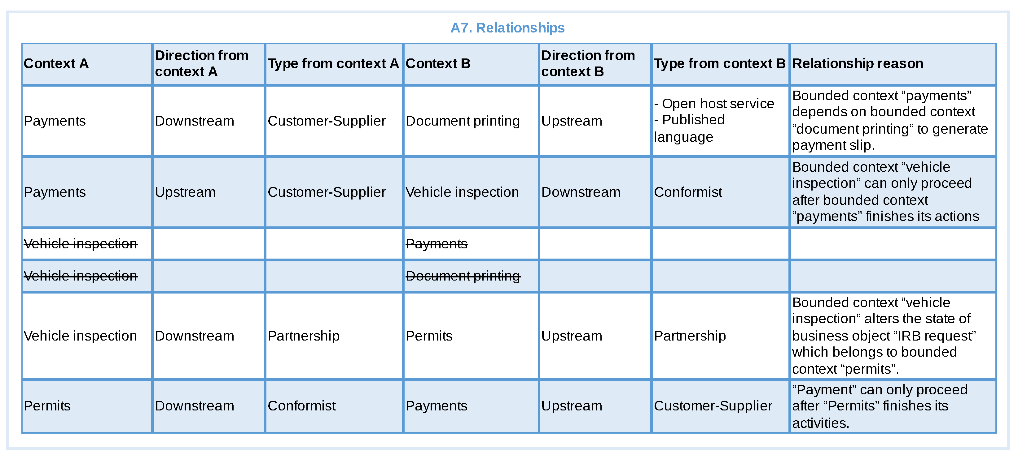
  • Partnership: Teams define a process to plan, develop and manage the integration between systems. They cooperate with each other in the evolution and maintenance of the interfaces of both systems.
  • Customer-Supplier Development: The upstream team (supplier) can be successful independent of the downstream team (customer). The needs of Downstream team are handled in various ways with consequences. However, the priorities of the downstream team are considered in the planning of the upstream team.
  • Conformist: The upstream team has no motivation to meet the needs of the downstream team. The translation complexity between the bounded contexts is eliminated and the downstream team faithfully adheres to the upstream team model.
  • Open Host Service: Defines a protocol for accessing subsystems as a set of services. Make the protocol explicit/public so that everyone who needs it can integrate into the system. The protocol can be improved and expanded when new requirements arise, except when a single team has an unusual need.
  • Published Language: Translating communication between models from two linked contexts requires a common language. A well-documented shared language must be maintained to express domain information necessary for communication.
To manage the complexity of large domains, these can be divided into subdomains. Subdomains can represent business areas or large system functionality, representing large placeholders of the domain problem [13]. According to Vernon [24], subdomains are classified as:
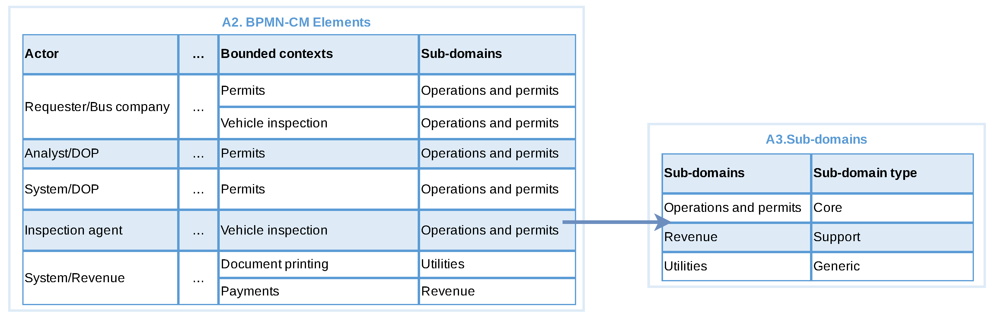
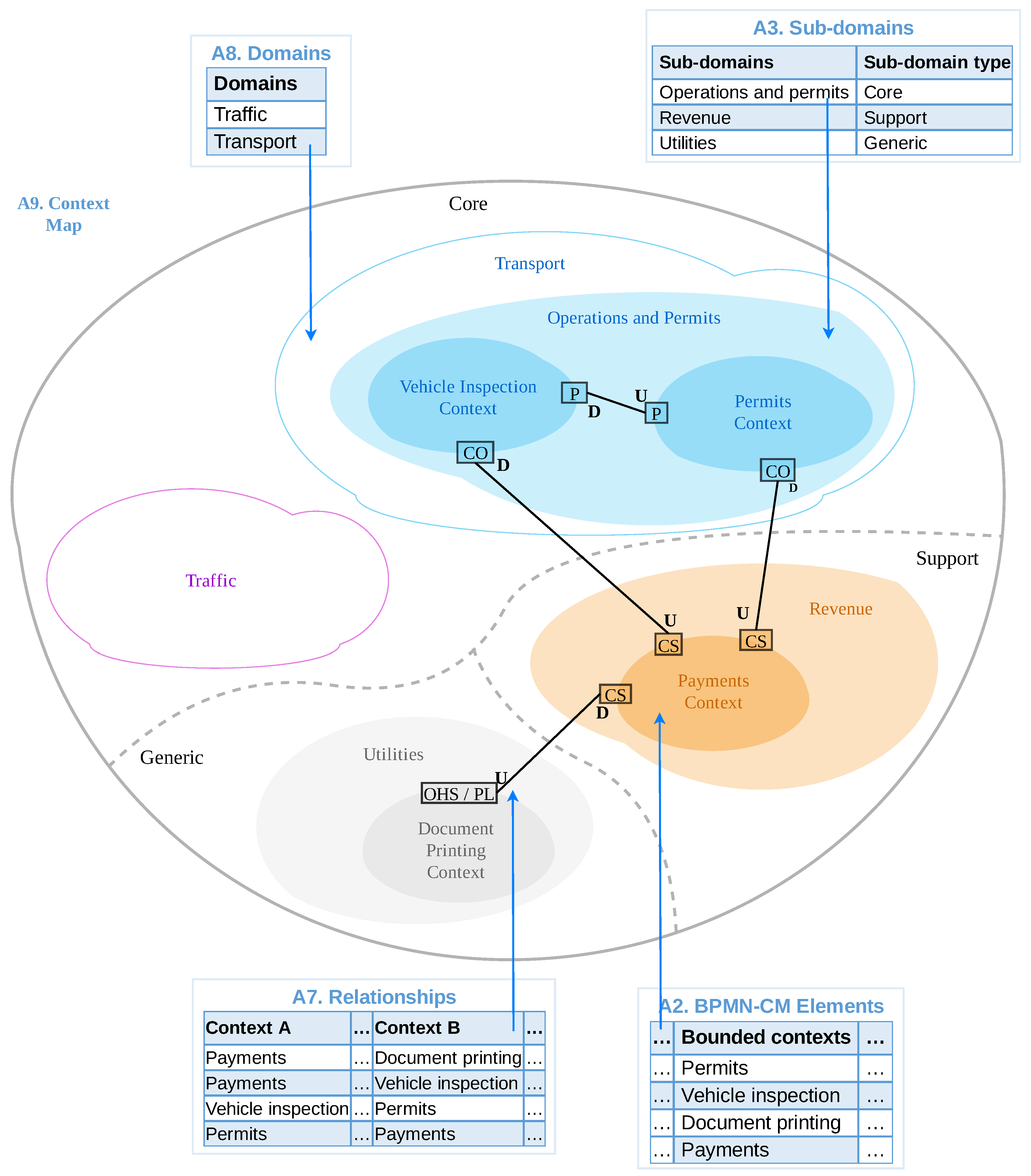
  • Core: Represents the main contexts or core of the business. It is usually linked to the organisation’s purpose activities.
  • Support: Represents contexts created to support the core business. They are not usually the organisation’s purpose activities, but they support it.
  • Generic: Represents contexts that don’t capture anything special for the business, but are needed for general solution.

2.2. Related Work

The main focus of our work is in the definition of a systematic approach for the use of business process models to build DDD artefacts in support of MSA. In conducting our literature review we used existing systematic literature reviews (SLR) on the topics mentioned above as starting point. We started by identifying SLR in the identification of MSA, and then extracted those works that explicitly explore business processes for identification of MSA. This has been complemented by searching the main indexing tools (i.e., ACM DL, IEEExplorer, and Science Direct) for works published after the SLRs. This was followed by a discussion on the use of DDD to build MSA. The same procedure has been applied, starting with existing SLRs complemented by searches for newly published works. The main criteria considered for inclusion was the definition of some systematic approach around DDD. We then focused our search for works that explicitly mention experiences in the building of DDD artefacts.
Business process models have been used as part of requirements engineering [16] with demonstrated improvement in the quantity and quality of requirements [25]. In fact, a number of works have explored business processes for identification of MSA. Götz et al. [26] proposed an approach to design microservices based on data objects of business process models, from the identification of relevant entities, their attributes, relationships and analysis of the frequency of use of this data. Analysing the approach, we can see a tendency for a given microservice to have too many responsibilities, due to the fact that it frequently uses a data object originally belonging to another business context, or the construction of very granular microservices, as it only takes into account the perspective of using a specific set of data. Costa and de Oliveira [27] proposed an approach to modelling SOA applications based on business objectives. From the process models, service requirements to achieve business objectives are extracted and converted into service specifications. Amiri et al. [6,28] proposed a method to identify microservices based on the analysis of the structural dependence between tasks of a business process, and data dependence of business objects that evaluate the readings and writings performed on these objects. Daoud et al. [29] extended the work of Amiri et al. [6,28] proposing a graph-based approach to identify microservices using clustering techniques. However, these works consider only two of the three aspects of the logical relationship of the process activities, observed in [29], namely: flow control and data dependence. When analysing these approaches it can be seen that only activities that are directly related or interrelated through a gateway are grouped to compose a microservice. The functional dependence between activities, which reveals how business contexts interact, is not considered. This means that if there is an activity that participates in the same business context and that does not have a connection with other activities in the same context, this activity will compose another separate microservice, erroneously fragmenting the services. On the other hand, composing a microservice based on the dependence of data objects can lead to a wrong grouping, since the same entity present in the business process can be used in different contexts, through specific models. Moreover, these approaches do not explore DDD in their identification efforts. The context map produced by BPM2DDD can be seen as an intermediate model, providing an overview of business contexts and their relationships. Compared to the works that explore business process models, BPM2DDD presents a new approach which takes into account not only the activities are directly related in the BPMN model (or only the data), but also other existing BPMN elements such as actors, pools, events and data objects to determine bounded contexts and their relationships.
As previously mentioned DDD is an approach from the beginning of 2000’s and has been used in different domain before the appearance of microservices. For example, Landre et al. [30] demonstrated in 2006 how DDD have been used to improve the software architecture of a large enterprise system by exploring context maps with bounded context and different types of relationships. More recently, Shenglin et al. [15] described how the use of DDD improved the development of prototypes for military information systems. However, those approaches do not detail how the context maps is constructed.
When we look at more systematic approaches involving DDD we can find a number of works that supports the creation of microservices from DDD artefacts. For example, the context mapper tool (https://contextmapper.org accessed on 2 September 2022) is a well-established framework to support the creation of DDD artefacts and their use for definition of microservices [31]. It provides a domain specific language for definition of DDD artefacts together with a set of tools based on model-driven engineering for the creation of context maps from source code or functional requirements, architectural design and code generation. Another work has been presented by Giallorenzo et al. [32], in which DDD models expressed in LEMMA domain data modelling language are automatically translated into microservice APIs using the Jolie programming language. Rademacher et al. [2] presented a methodology based on model-driven engineering to transform domain models into microservice architecture models that are then used to generate code where each microservice is mapped to a bounded context. In fact, a number of studies have identified DDD as one of the most used approaches for creating microservices [8,9,10,11].
However, existing literature in the subject is mainly focused on defining its base concepts and principles [1], or in identifying a number of design patterns with examples of their respective use [5,14,33]. The works that do mention the construction of DDD artefacts are usually focused on describing their respective domain model and how the different patterns have been used, e.g., [34], or point to general guidance to be used for this particular activity [35].
There are approaches that include some degree of systematisation in the construction of DDD artefacts based on the decomposition of functional requirements (usually use cases). For example, Santos et al. [36] presented an approach for modelling architectures in agile software development in which one of the steps in their process is the application of DDD to help in the requirements elicitation. Their approach explores “use case models structured by decomposing functionalities in a tree-like form” in which the different groups of use cases correspond to domains and sub-domains and reflect the frontiers used to identify bounded contexts [37]. Other approaches [38,39] use functional decomposition of use cases, through the analysis of relationships between system operations (use cases) and data read or written by such operations. These are then modelled as graphs and clustering techniques are used to group data and operations into a business capability, which is then considered as a microservice candidate.
The approach that is closest to ours is presented by Hippchen et al. [12,40], which proposed a systematic method for the use of DDD to create microservices. They define a process in which the several activities of DDD are positioned in the software development life-cycle [40]. This process includes as one of their steps the construction of DDD artefacts (bounded contexts, their relationships and context maps) based on the use of behaviour driven design features to identify the initial domain model [12]. However, their approach direct the reader to the initial DDD book by Evans [1] for guidance in how to define bounded contexts. Moreover, their approach defines a new purpose for context maps, different from the original definitions, which is used by the majority of works.
Finally, it is worth mentioning that there is a variety of works in the literature to identify microservices using other strategies [8] (e.g., API specifications [41], analysis of legacy monolithic systems [42] and functional decomposition [43]), but these will not be explored here as they are considered out of scope of our approach.
In fact, we could not identify any systematic approach that builds context maps from business process models. Thus our approach not only fills an existing gap, but can be easily be treated as complementary to existing approaches.

3. The BPM2DDD Approach

The objective of the BPM2DDD is to create a context map based on the analysis of business process models. The context map captures the business domain of the organisation, serving as one of the inputs to the modelling phase of the software development process, and contributing for the identification of the candidate services that will compose a service-oriented solution.
The approach expects as input a BPMN model which is then processed through three main phases: In phase 1 we analyse the input BPMN model according to a minimal set of requirements established by the approach. In phase 2 we process the BPMN model, extracting information to identify bounded contexts and their relationships. Finally, in phase 3 we review the created context map with domain specialists, going back to phase 2 if needed. The approach assumes the availability of domain specialists during all phases.
In the subsequent subsections, we present a contextualisation and describe the methodology employed in the development of BPM2DDD, followed by a description of its three phases.

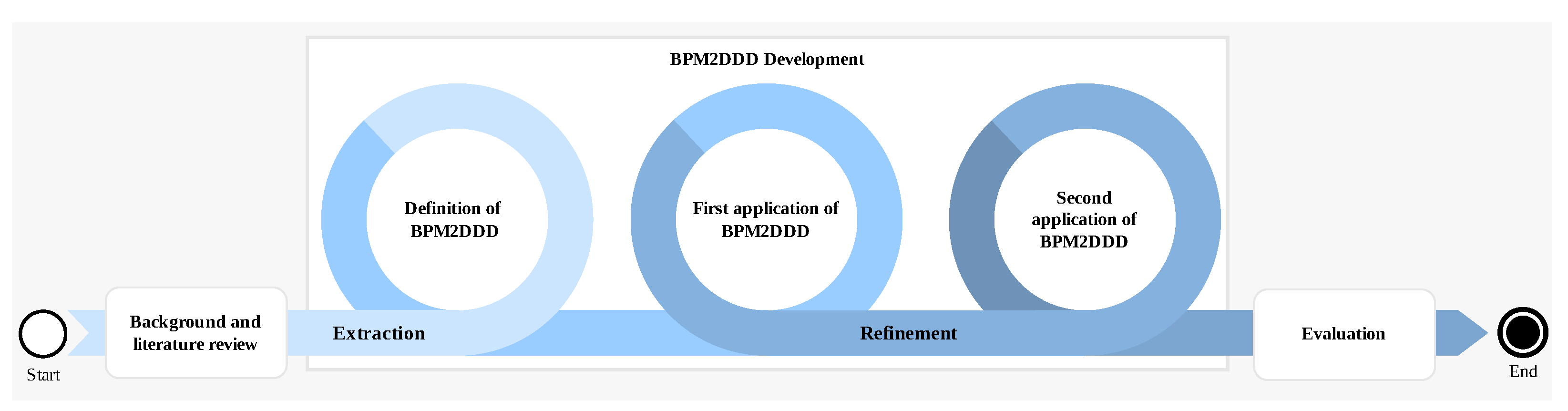
3.1. Contextualisation and Methodology

The BPM2DDD approach has been developed and applied between June/2019 and March/2020 as part of a real software development project in a Brazilian governmental organ of urban transit control. One of the authors was part of an outsourced team composed of six developers working together with a team of nine developers in a project for the reengineering of their internal systems together with the addition of new functionalities. This project was being developed according to the SPReaD (Service-oriented Process for Reengineering and Devops) process [19], an instantiation of the mainstream SOA methodology that defines a set of concrete steps and techniques to support the development of service-oriented systems. This project involved the use of business process models to aid in the requirements elicitation, resulting in the creation of BoAT (Box Analogy Technique) [16], an agile-based approach for the capture of business process models in group interviews with domain specialists. BoAT was the technique applied for the construction of the business processes models explored in this work.
In this context, we identified the need for a systematic approach to help in the analysis of business process models for identifying bounded contexts and context maps. This was the main motivation for the BPM2DDD approach, which has been developed according to the methodology presented in Figure 2. We started by conducting a background and literature review in the topics of business process management as part of requirements engineering, service oriented architecture and microservices, and domain-driven design. Our review was targeted at approachs for creation of context maps with identification of domains and bounded contexts, which has been presented in Section 2.
The development of the BPM2DDD approach happened in two stages. During the extraction stage we systematised the different steps and best-practices from the literature in a concrete process. We then applied the BPM2DDD approach to a real business process, together with the domain specialists that defined the business process model. This provided us feedback that has been incorporated during the refinement stage and then applied to a second business process, resulting in the description presented in this article.
Finally, we performed an evaluation of our approach by (1) validating the created context map with domain specialists and the development team; and (2) by conducting a comparative application of BPM2DDD by two external analysts. The evaluation details are presented in Section 5.
In the sequence we present the three phases that compose the BPM2DDD approach.

3.2. Phase1: Review Input BPMN

The BPM2DDD technique is sensitive to the level of detail present in the BPMN model, and the quality of the model provided is a determining factor for the quality of the context map generated. This phase analyses the provided BPMN model taking into consideration the following points:
  • Pools The BPMN model must have at least one pool, which represents a clear organisational boundary like a company. Separate pools should be used for external organisations.
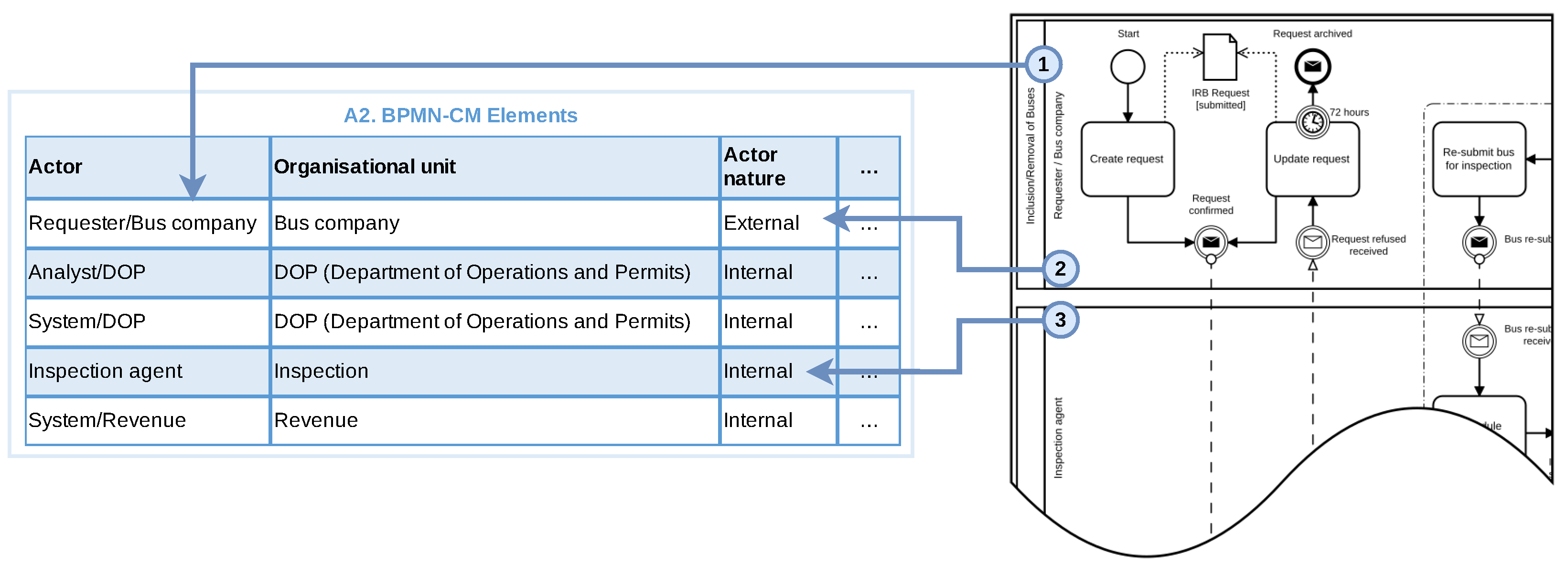
  • Lanes Pools must have at least one lane, which represents one actor in the process. An actor is formed by a role (function) plus an organisational unit (e.g., department).
  • Systemic actors Automated activities performed by some system should be explicitly modelled with a systemic actor.
  • Activities Activities should represent a job to be performed and always be assigned to a lane.
  • Sub-processes and groups: Activities can be grouped together using sub-processes or the BPMN group element.
  • Control flow: The control flow (sequence, merge and split gateway) should be explicitly used.
  • Events Each process should have explicit start and end events. Each event should have a start event and an end event to denote the completion of the event.
  • Communication and message flows Communication between actors should be explicitly modelled with communication events and message flows. Message flows should be used to communicate between pools.
  • Data objects Data objects and data stores should be explicitly used to represent documents, artefacts or information flow throughout the process.
These provide general guidance to the elements that we expect in a BPMN model and their absence does not prevent the execution of the technique, but makes it difficult to identify the respective domain elements, resulting in context map with fewer details and that does not adequately reflect the domain of the organisation.
To help with this we have defined a set of questions that can be used to query the BPMN model together with business analysts and domain specialists.
  • Does the business process model actually mirror the operational reality?
  • Are there pools or lanes that demonstrate which actors are involved in the process?
  • Do the actors make their role and organisational unit of origin explicit?
  • If there are external actors, are they allocated in separate pools/lanes?
  • If any, are automated activities allocated to systemic actors?
  • If any, are related activities grouped into BPMN sub-processes or groups?
  • If any, are communications explicit in the model through communication events and message flows?
  • If any, are there data objects that demonstrate the sharing of information between process activities?
If there is any negative response to this assessment, the BPMN model is considered not sufficient, and therefore needs to be refined by business analysts before the technique can be applied. The construction and refinement of the BPMN model, as well as the indication if a model is right or wrong, is out of scope of this work and can employ any of the techniques available (e.g., [16]) together with domain specialists.

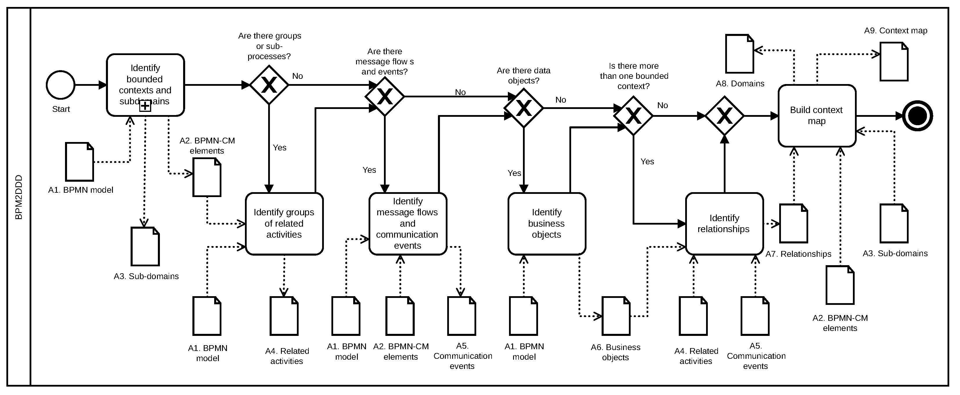
3.3. Phase2: Build Context Map

In this phase we produce the context map from the BPMN model. Figure 3 presents the main activities of this phase using a BPMN notation and identifying all the artefacts produced/consumed by each step. The end-to-end process contains six main steps (a) Identify bounded contexts and subdomains, (b) Identify groups of related activities, (c) Identify Message Flows and communication events, (d) Identify Business Objects, (e) Identify relationships and (f) Build Context Map.
We describe the steps in the following sub-sections. The description will contain a brief explanation about the step, the activities to be carried out during the step and an outline of its output, which is used in the subsequent steps. We will not present the template of the outputs here as example outputs are shown in subsequent section where we demonstrate how we have applied our BPM2DDD approach in real life scenario, and the structure of each artefact is presented in the Appendix A.

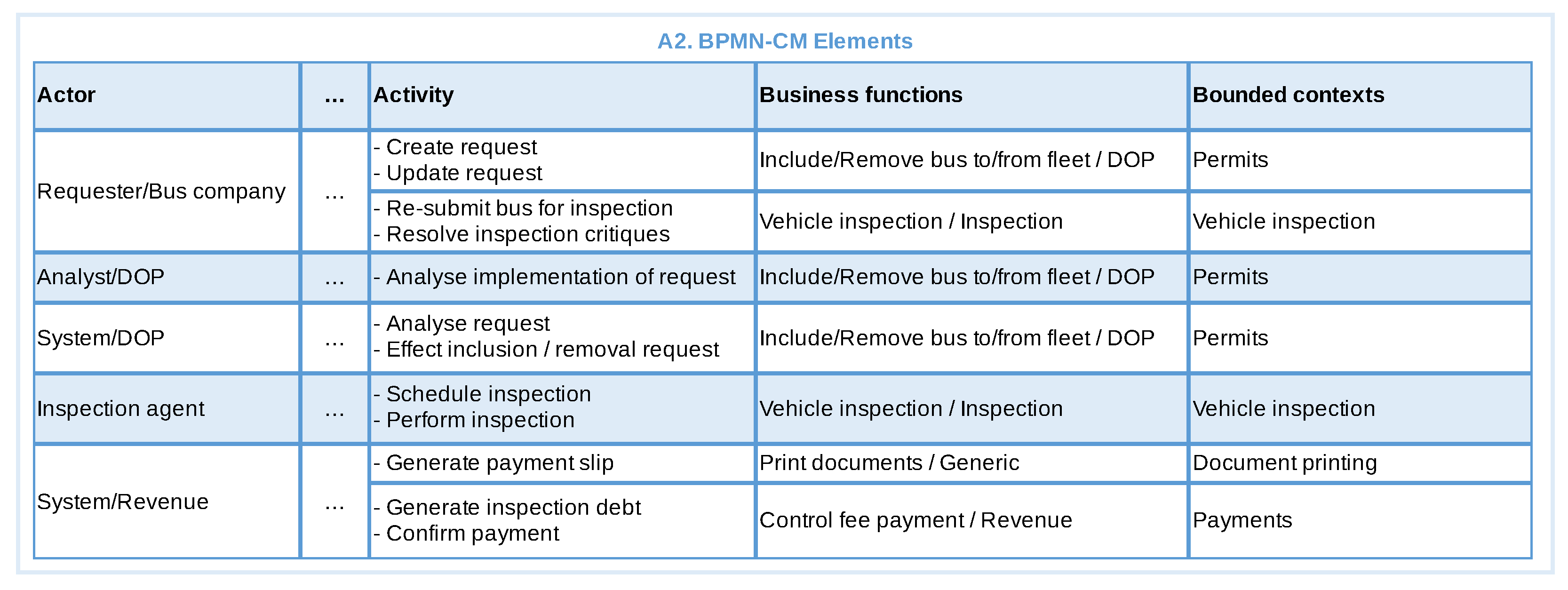
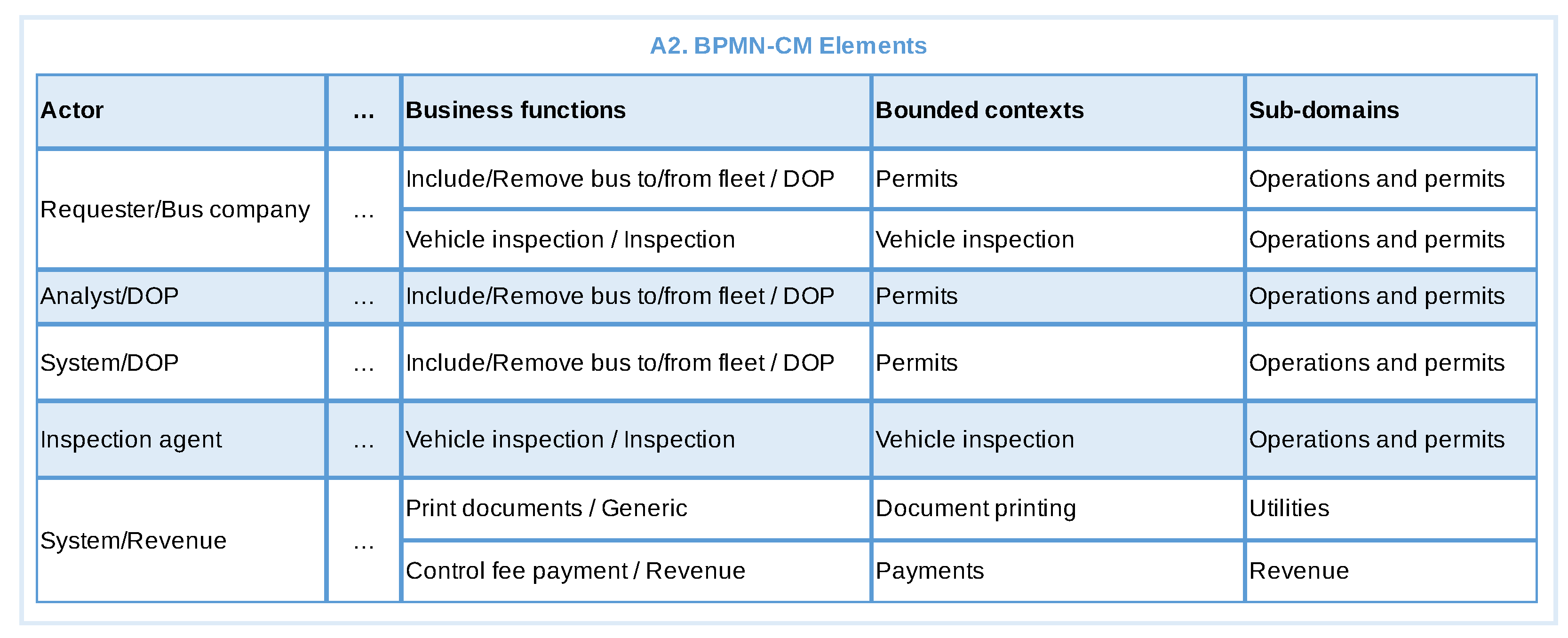
3.3.1. Identify Bounded Contexts and Subdomains

The first step in our approach is to identify the bounded contexts and the subdomains. This step receives as input the BPMN model (A1) and produces two artefacts: BPMN-CM (BPMN Context Map) elements (A2) and Sub-domains (A3). A2 contains different elements of the BPMN model while A3 contains the subdomains names and types. Figure 4 presents a BPMN description of this step, which will be detailed in the sequence.
We start by identifying the actors (based on lanes) and activities of the BPMN model, which are stored in A10 (Activities/actors), an auxiliary artefact with the list of actors, their activities, the objective and the obtained results of each activity. Each actor and its respective organisational unit (OU) are added to the A2 artefact, where they are classified according to their nature (internal/external based on its pool in the BPMN) and type (consumer/provider based on whether the actor provides or consumes services - an actor can do both in a single process). We also record the purpose and/or responsibility of each organisational unit in A2 and identify from which OU the actor consumes or provides services to.
In order to classify the actors we provide the following guidance: For each pair of actors A and B in A2 the following points should be considered:
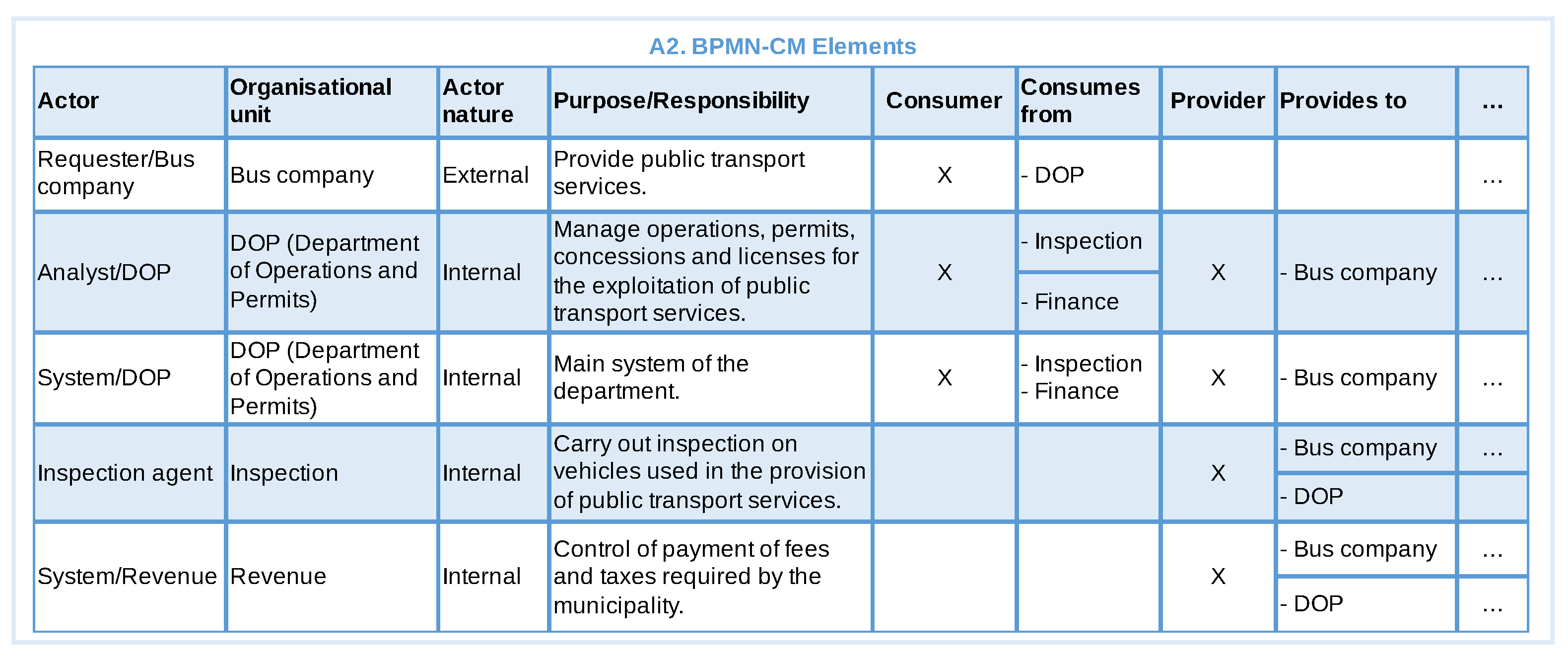
  • What is the role or responsibility of organisational unit of actor B in the business context under consideration?
  • What is the objective of each activity performed by actor B?
  • Is the result produced by the activities of an actor B of interest, direct dependence or acceptance criteria for the organisational unit of actor A to fulfil its role, achieve its objective or perform some activity? Yes or No.
  • Does the result produced by the activities of actor B modify the state of some BPMN data object used by actor A? Yes or No.
If the answers to questions 3 and 4 are yes, actor A must be classified as “Consumer” while actor B must be classified as “Provider”.
Once a relationship of consumer-provider has been established between actors A and B in A2, actor A must be marked with “Yes” in column Consumer and the organisational unit of actor B must be registered in column Consumes from, while actor B must be marked with “Yes” in the Provider column and the organisational unit of actor A must be recorded in the Provides to column. At the end of this, the objective of both organisation units in this business context are added to the column Purpose/Responsibility of the respective Organisational Unit.
Next, the activities of A10 are ordered and grouped together in the A2 artefact, for each actor, based on the similarity of their objectives and produced results (Identify groups of activities). These are then used to identify all possible business functions in A2 (Identify business functions). Business functions conceptualise the mission and services provided by organisational unit. We consider the purpose of the organisational unit, in addition to activities objectives and obtained results from A10, to arrive at business functions. Multiple activities in a group can be realised through one or more business function, and on the contrary one business function can realise multiple activities across different groups. We suggest the naming of business functions to be done with name plus the name of the organisational unit to which it belongs.
We suggest two approaches for the identification of business functions:
  • Approach by activity: Based on the analysis of the objectives and obtained results produced by the activities (or group of activities).
  • Approach by organisational unit: Based on the analysis of the objectives or responsibilities of each organisational unit.
Once the business functions are defined we generalise them to identify bounded contexts. These contexts depict a broad level solution structure and at this point are considered as candidate bounded contexts. They can be defined based on domain information, or directly converted from business function names if it can not be generalised. Information about bounded contexts is stored in A2.
Based on the organisation units and bounded contexts we can identify subdomains and types, which are stored in A3. Autonomous organisational units (i.e., not subordinate to another organisational unit) are strong candidates to be mapped into subdomains. External organisational units can also be mapped to subdomains as long as they are properly identified as external in the context map. Bounded contexts can be directly mapped or grouped (e.g., by level of similarity) into a new abstraction that will be their subdomain. The entire set of subdomains should cover all bounded contexts, and each bounded context can only be mapped to a specific subdomain. In a worst-case scenario, there will be only one subdomain. Subdomains are then classified into types (core, support and generic) based on the definition of Section 2.

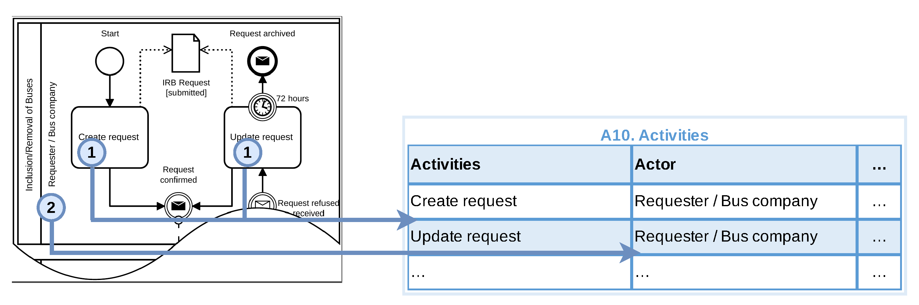
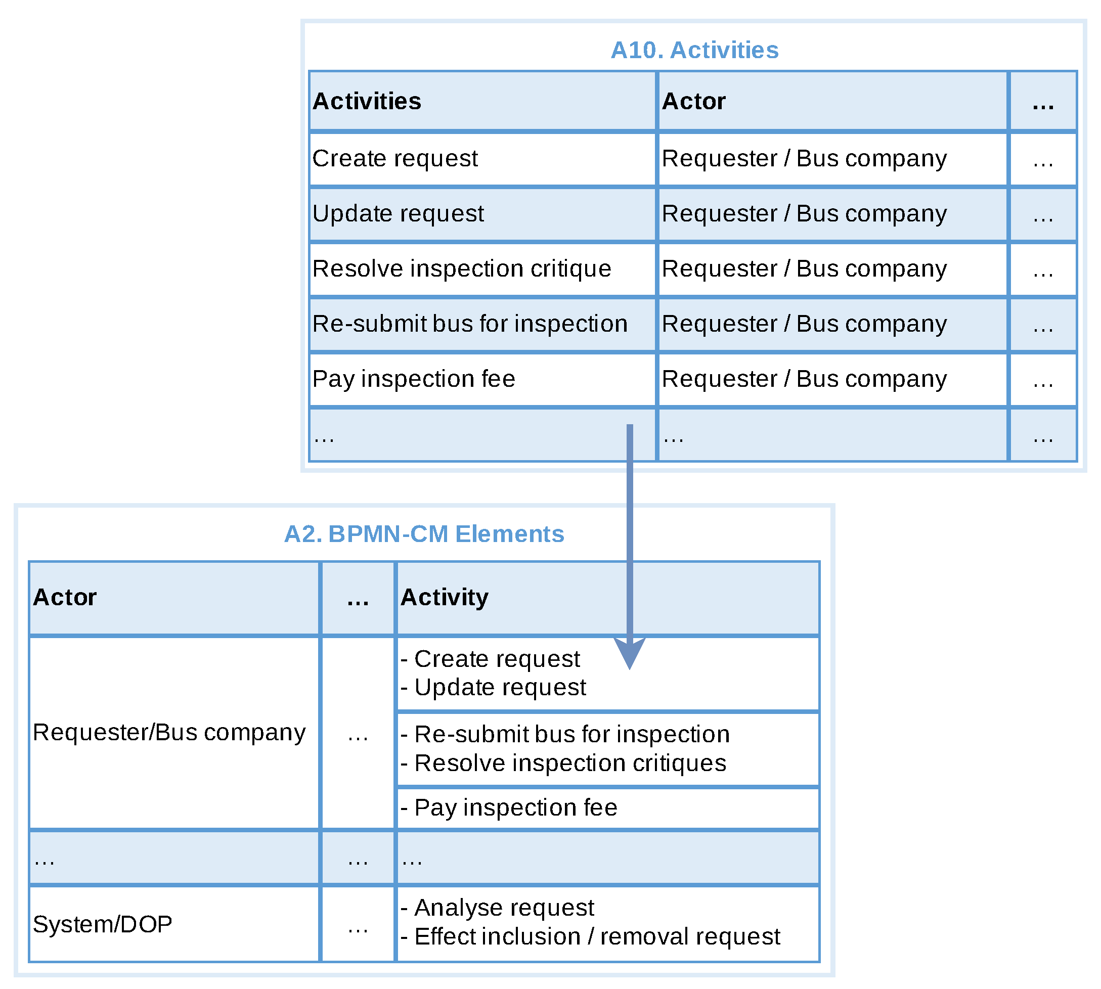
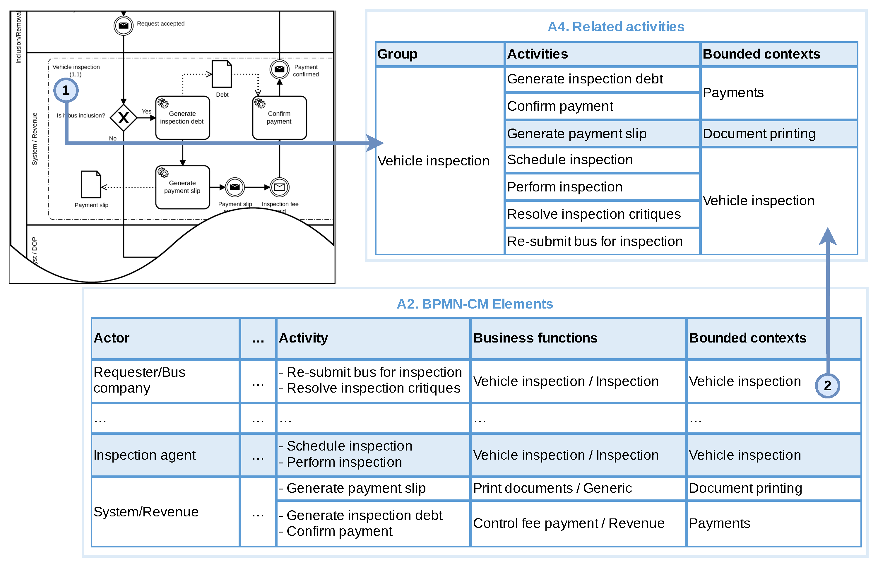
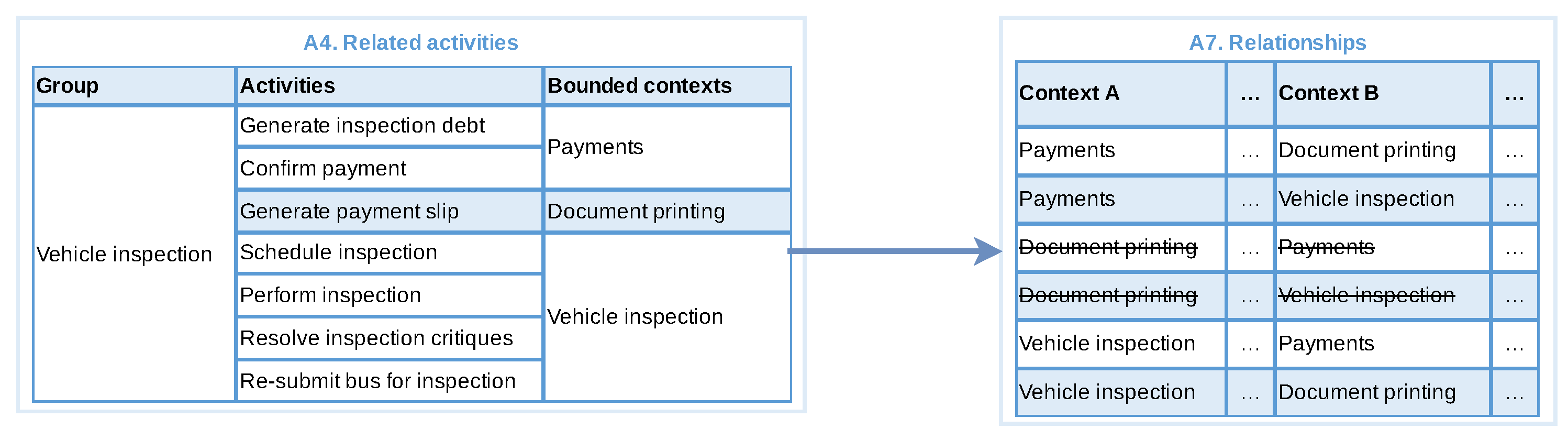
3.3.2. Identify Groups of Related Activities

This step is applicable if the main BPMN model contains sub-processes or groups. In this step, we aim to identify activities within different sub-processes or groups that are related to similar business activities and group them together. This kind of grouping help us in identifying the relationship between bounded contexts.
This step generates the artefact Related activities (A4), which stores a name for the group, the activities of the group and their respective bounded contexts. First we observe sub-processes and BPMN groups extracting the related activities into A4. These activities can be from different actors and/or business contexts. The groups are then named and the bounded contexts associated with those activities are obtained from A2.

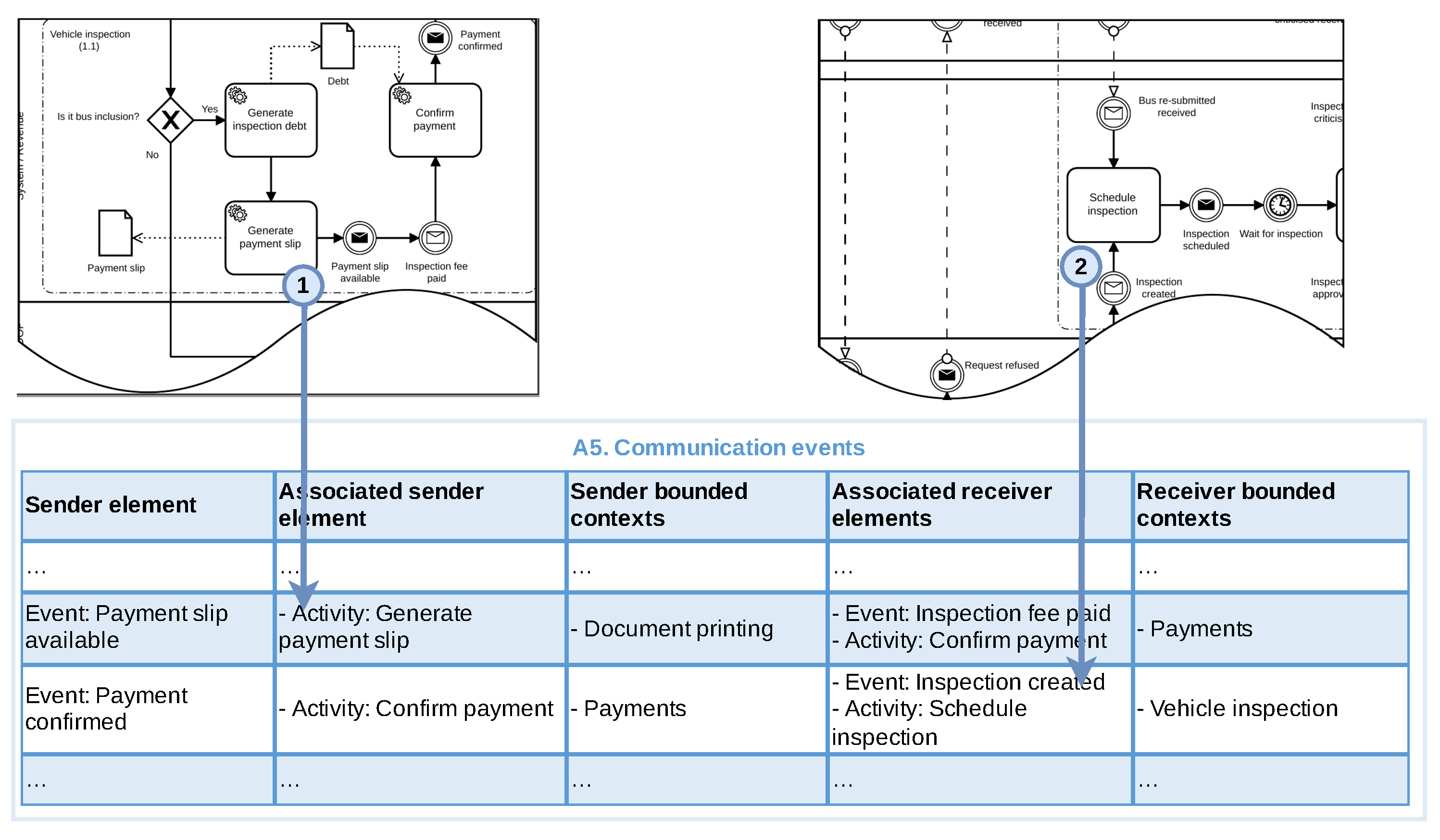
3.3.3. Identify Message Flows and Communication Events

This step is applicable if the process contains events or message flows. In this step, we capture the communications between different elements in the BPMN model. Communication can occur during or after the execution of an activity, sub-process or external process, either within the same or between different bounded contexts. This step generates the artefact communication events (A5), which stores information about the elements that initiated and received the communication, i.e., the sender/receiver event, its associated elements and bounded contexts.
We start by identifying all launch events (e.g., messages or signal) and the activities that precede these events, followed by their respective received elements (events and associated activities). Communication events that occur at the end of the process can be ignored, as they only represent a notification that the process has ended, and no return communication is expected. Finally, we attach the already identified bounded contexts with the sender and receiver associated elements. The information identified during this step is updated in A5.
Special care is needed with sender bounded contexts that are associated with generic subdomains, as these are usually not involved in specific business logic. In this case, it is necessary to identify which bounded context is responsible for triggering the generic bounded context and classify the first as the source of the communication, while the second will be the receiver of the communication.

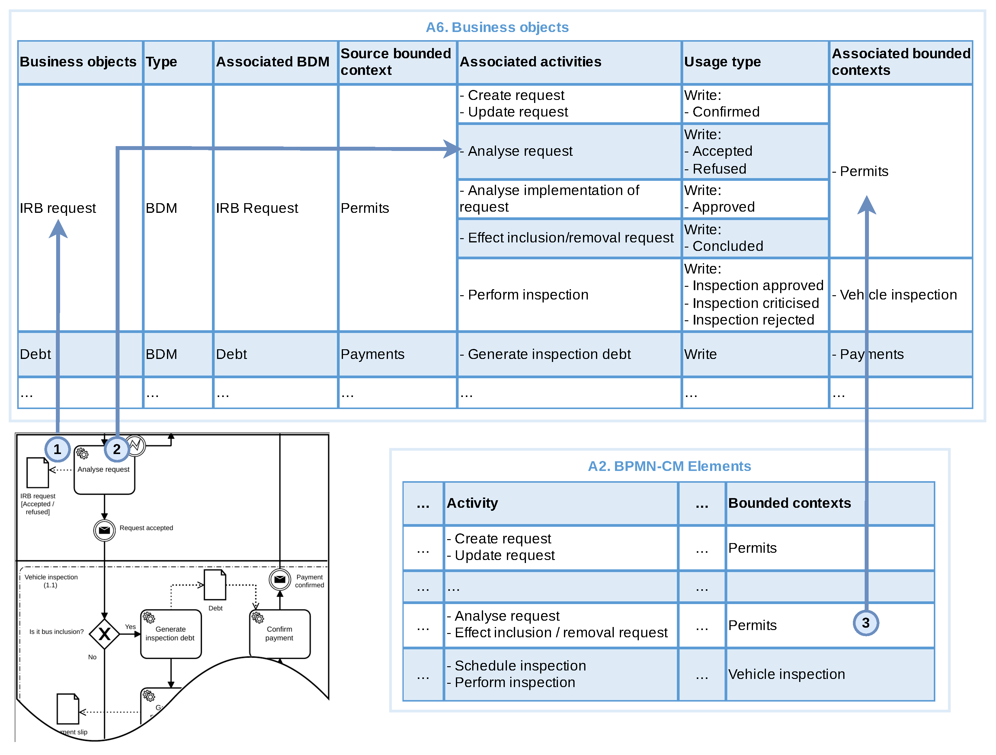
3.3.4. Identify Business Objects

This step is applicable if the BPMN model contains data elements (business objects and/or data storage objects). In this step, we extract and classify the data elements in the artefact Business objects (A6).
A business object can be classified according to its type: document (physical or digital) or BDM for Business Data Model. Each object is related to an associated BDM, which can be the object itself or another term that represents an enterprise data model or entity. Once the business objects are identified, we capture the activities associated with the object and their respective bounded contexts. In particular, we are looking to differentiate the source bounded context (in which the object belongs to) from those bounded contexts (and respective activities) that use the business object. We also look at how the business object is used by each activity, i.e., read, write or both.
We have identified a set of questions that can help in this step:
  • In what bounded context is the business object created? If an activity is responsible for creating a business object, it is likely that the source of this object is the bounded context to which this activity belongs to.
  • How often is this business object used in activities in the same bounded context? If a business object is used by several activities that belong to the same bounded context, it is likely that this object belongs to that context.
  • Is the data object’s name, terminology, and meaning closely related to the bounded contexts in which it is used? If when comparing a business object with a bounded context that uses it, their names, terminology, or meanings are close, it is likely that the object belongs to that context.

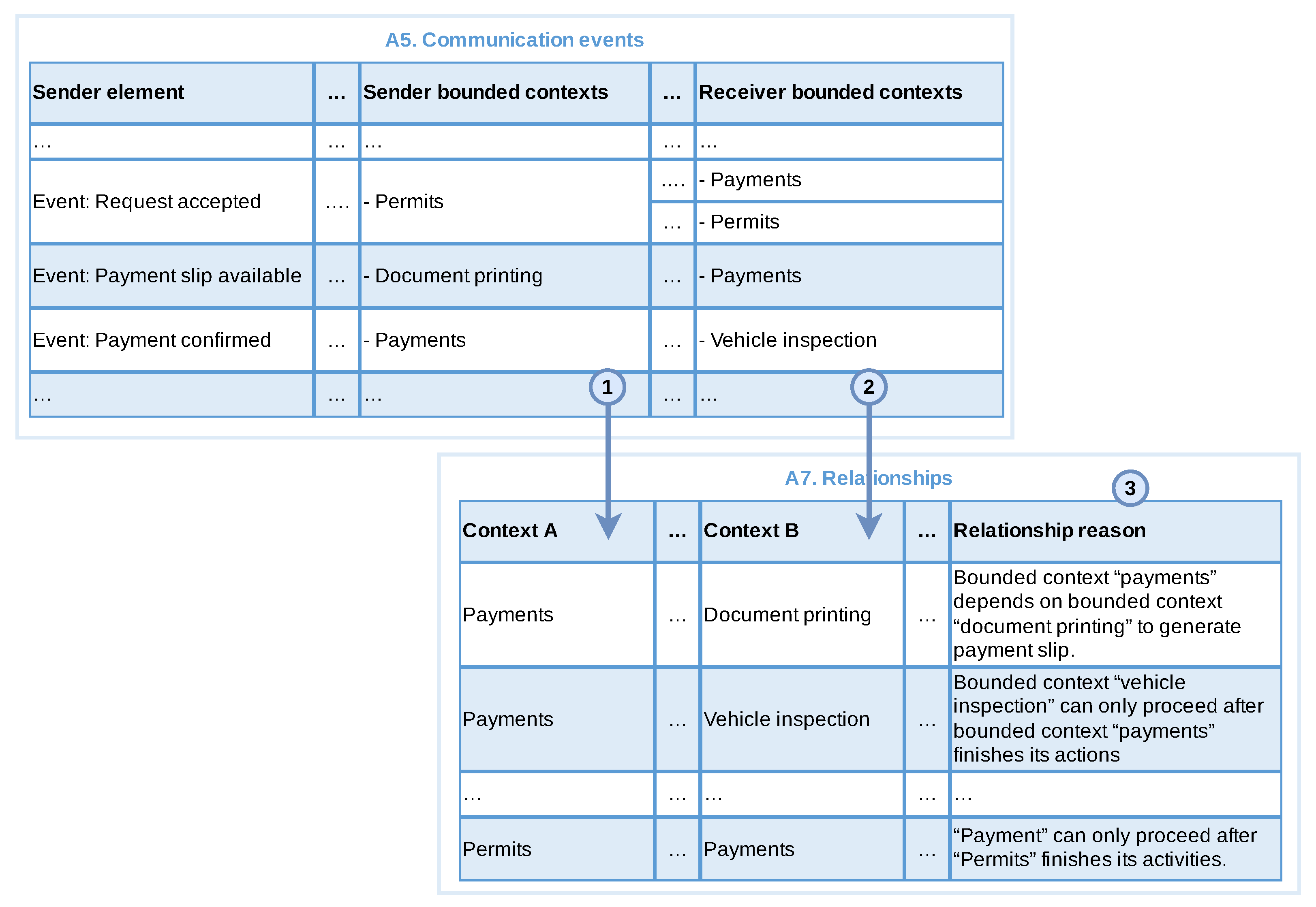
3.3.5. Identify Relationships

This step is applicable if there are more than one bounded context. In this step, we identify the relationships between bounded contexts, and their types, which are stored in the artefact Relations (A7). This is done based on the produced artefacts A4 (related activities), A5 (communication events) and A6 (business objects).
At the beginning, we identify the bounded contexts participating in a group from artefact A4. We take each pair of bounded contexts as an ordered pair (Context A, Context B) in A7. As generic bounded contexts are not directly related to business objective, they cannot be Context A. The exception to this rule is only if both contexts belong to a subdomain of the type generic.
We now do the same for artefact A5 (Communication events). A sender bounded context is mapped as Context A and the receiver bounded contexts are mapped as Context B. Then for each pair of contexts in A7 we record the reason for the relationship. We do not include duplicate pairs or reasons.
Similarly, we identify relationships and their reason for each pair of bounded contexts from artefact A6 based on their interaction with business objects. In this case, the source bounded context is mapped to Context B, while associated bounded contexts are captured as Context A. If there is already a combination for these contexts in A7, it can be reused.
After these sub-steps, we discard duplicate relationships, relationships in which Context A is equal to Context B, and those relationship for which an explicit reason for its existence can not be identified.
Then for each pair having a relationship reason, we identify the direction and type from both sides of the relationship. The direction can be upstream or downstream based on, for example, the use of business objects or the communication between bounded contexts. Considering business objects (A6), when a given context depends on information from another context, the context holding the information (the source context) will have its direction defined as upstream and the context that needs the information as downstream. Considering communication events (A5), a receiver bounded context will normally only be able to continue with the execution of its activities when the sender bounded context of the communication completes its actions. Thus, the receiver context can be classified as downstream and the communication sender bounded context as upstream. Generic bounded contexts are classified as upstream, unless they depend on or needs to access resources from another generic context, in which case it can be classified as downstream.
Relationship types can be any of the types provided by DDD, and exemplified in Section 2. Although DDD makes it clear which types of relationships can exist, this technique only helps the systems analyst to discover which bounded contexts exist and which they will relate to based on the analysis of the business process model. Therefore, the definition of relationship types should take into account the relationships between contexts, project resources/constraints and team limitations.

3.3.6. Build Context Map

This is the final step of the technique, in which we create the context map, and that will be used by the development team to create the services. At this point, we have the domains (A8), the subdomains (A3), bounded contexts (A2) and the relationship between them (A7). Using this information this step generates two artefacts: domains (A8) and context map (A9).
To begin with, we capture the organisation’s domains in A8. The domains directly map with the organisation’s business process and will involve all subdomains identified before. Eventually, other sources of information might be need for this step, which will also identify the main domain of the organisation. Then the remaining artefacts are used to draw the context map. After the initial drawing we can reorganise the map elements to make the diagram easier to read.

3.4. Phase3: Review

In this phase, we present the artefacts and context map to the business analysts and/or domain specialist to get their feedback. Business process models do not always reveal all the information needed to create a complete context map, as they may represent only a small portion of an organisation’s operations, providing a limited view of its domain. Thus, we have identified the following set of questions to guide the review of the produced artefacts:
  • Do the domains represent the organisational focus?
  • Do the identified subdomains maps with organisational objectives?
  • Do bounded contexts represent existing business contexts of the organisation?
  • Is the mapping between sub-domains and bounded contexts aligned with organisation business?
  • Are business functions implemented as part of a context reflecting the business functions of the organisation?
  • Are the relationships between the bounded contexts aligned with the business?
If any inconsistency is detected we can go back to phase 2, re-executing previous steps that extract information from the business process for the purpose of improving the information and adjusting the context map.

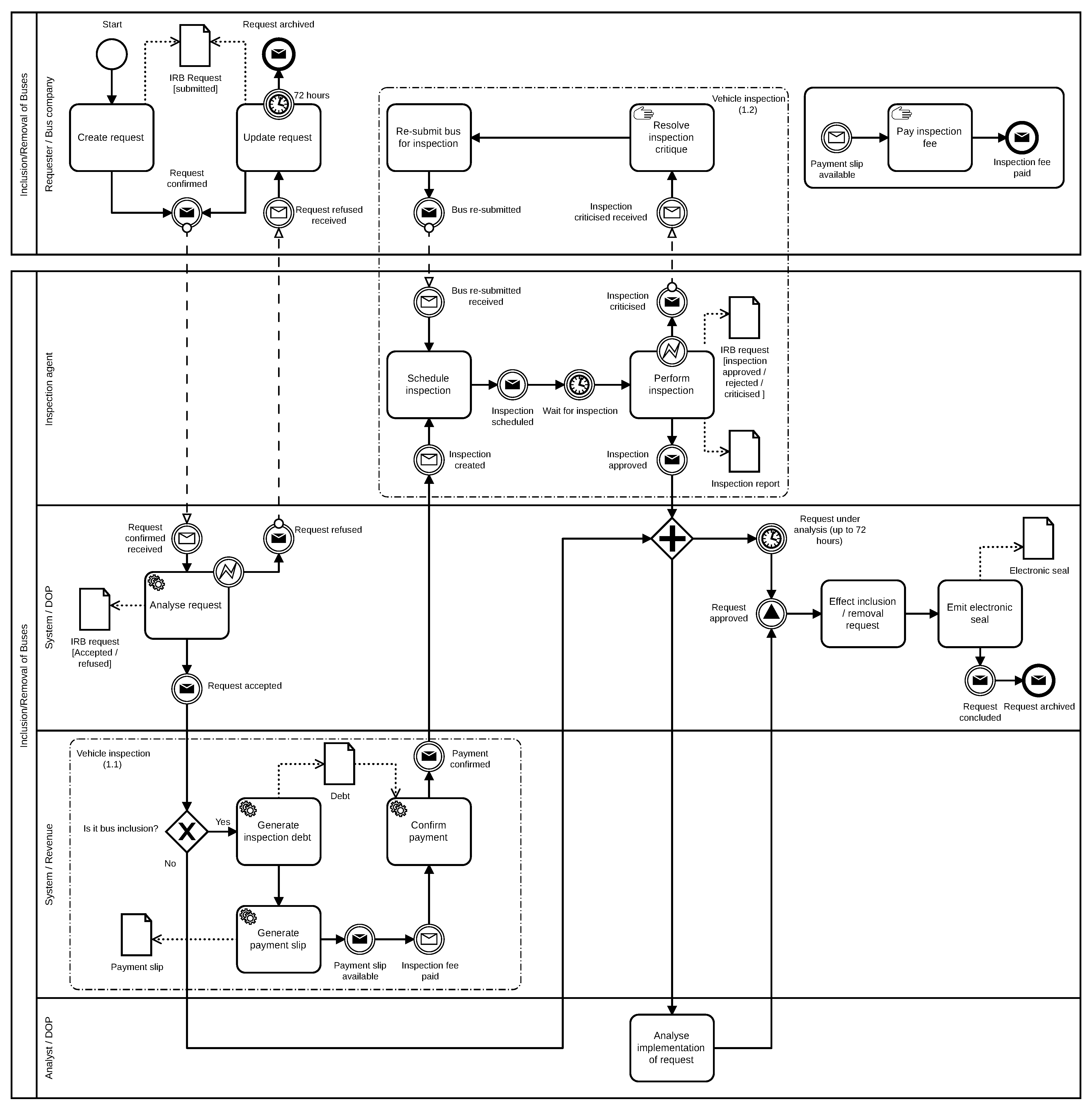
4. Application of the Technique

This section presents an example of the application of the BPM2DDD using a real business process. We start by contextualising the business process and scenario used as example, followed by a description according with the three phases of the BPM2DDD approach.

4.1. Contextualisation of the Example Application

As previously mentioned, BPM2DDD was initially applied to two business processes as part of the development of new services in a real project. These have produced the context map that was used by the team in their development of the identified services. It is important to mention that this article focuses on the use of BPM2DDD to identify the context map, while its use in the other activities of the software development life-cycle is considered out of scope. In this particular case, the development team followed the guidance of the SPReaD process [19], a service-oriented approach for the development of microservice architectures after the context map has been delivered.
In this section we present the application of BPM2DDD to the IRB process (Inclusion/Removal of buses), the business process responsible for including or removing buses from the fleet serving the city. This process has been chosen here because it is simple enough to be explored in the article but also covers all aspects of the BPM2DDD approach. This business process has been captured and refined (as part of phase 1 of BPM2DDD) together with domain specialists using the BoAT [16] technique. We present phases 1 and 2 in this section describing examples of the generated artefacts following the step-by-step description of BPM2DDD. Phase 3 is detailed in the next section as part of the evaluation of the approach.

4.2. Phase 1: Review Input BPMN—IRB Process

Figure 5 presents the BPMN model of the process for Inclusion/Removal of Buses (IRB) which is briefly described in the sequence. This process is used by bus companies to include or remove buses from the running fleet. It starts by a bus company creating a new request (Create request), which is analysed by a system (Analyse request). If the request is incomplete (e.g missing information) it is returned to the bus company which can update and re-submit the request (Update request).
Once the request is considered as accepted it can then proceed in the process. If the request involves the removal of buses it goes for analysis (Analyse implementation of request) before being effected into the system (Effect inclusion/removal request) and emission of the electronic seal that confirm the conclusion of the process as indicated by the message end event request archived. Bus inclusions require the payment of a fee before the bus can be inspected. An inspection fee constitutes a debt in name of the company within the city council (Generate inspection debt), which is then used to generate a payment slip (Generate payment slip). Once the payment is confirmed (Confirm payment) an inspection can be scheduled by an inspection agent (Schedule inspection). Upon inspection (Perform inspection) the bus can be considered as approved, which moves the process towards the final analysis (Analyse implementation of request) and effective inclusion of the bus in the system (Effect inclusion/removal request) and emission of electronic seal. An inspection can be “criticised”, in which case the bus company acts upon to resolve the problems pointed (Resolve inspection critique) and then re-submit the bus for inspection, which will be scheduled and performed by an inspection agent.
The BPMN model wass discussed together with domain specialists and business analysts using our set of questions (presented in Section 3.2). Upon analysis it was agreed that the process does reflect the operational reality, and employs pools and lanes for identifying internal and external actors, with their respective role and organisation unit. Automated activities are allocated to systemic actors, and BPMN groups are used for related activities, together with explicit communication elements and business objects.

4.3. Phase 2: Build Context Map—IRB Process

In the sequence we present examples of the artefacts created when following the instructions presented from Section 3.3.

4.3.1. Identify Bounded Contexts and Subdomains—IRB Process

The first step was to identify actors and activities in the auxiliary artefact A10. Figure 6 presents an snapshot of this artefact for two activities of the actor Requester/Bus Company. We also record the objectives and obtained results of each activity in A10.
The five actors and their respective organisational unit are extracted from pools and lanes into artefact A2. From the pools we find out that Requester/Bus company is an external actor and the other four actors are internal to the system. An example of the artefact A2 after this step is presented in Figure 7.
Actors are also classified as consumer/provider (as shown in Figure 8) following the guidance of Section 3.3.1. For example, the role of organisation unit DOP is to manage the operations and emission of licences, concessions and authorisation for exploitation of public transport services; The activity Analyse request has the objective of analysing the submitted request to check whether all required information has been provided. The result of this activity is of interest of organisation unit Bus company as the request must be accepted in order to include/remove a bus from the fleet. This activity also alters the state of object IRB request to Accepted or Refused. Thus, we understand that the actor Requester/Bus company consumes business functions from on organisation unit DOP. This is recorded in A2 (Figure 8). On the other hand, the link between activities Analyse request and Update request does not represent any business function, being a return of a previous request.
Next we look at the functional similarities between the activities recorded in the artefact A10 and group them accordingly in A2. For example the Create request and the Update request activities of Requester/Bus Company relates to request of inclusion or removal of bus from road. So we group these two activities together as shown in the example of Figure 9.
From the group of activities in A2 we identify business functions, as shown in the example of Figure 10. We notice that one function can realise multiple activities. For example the group of activities Create request and Update request of the actor Requester/Bus company can be realised through a business function Include/Remove bus to/from fleet/DOP. This business function is also associated to other groups of activities. Other business functions are also identified in this example, and one activity (Pay inspection fee) has been considered not associated to any business function, and thus discarded. On the other hand, when considering organisation units, the actor System/Revenue has been associated with the business function control fee payment/revenue based on the objectives of its organisation unit previously identified.
To identify bounded contexts we generalise business functions, as shown in Figure 10. For example the Include/Remove bus function identified above are related with the alteration on a permit to exploit public transport and thus can be abstracted to a candidate context Permits. It is part of the solution and can represent all business functions related to permits. A similar reasoning was applied to identify the candidate bounded context vehicle inspection.
Sub-domains are identified based on the organisational units and bounded contexts. Figure 11 shows a snapshot of artefact A2 with the sub-domains identified. In this example we can identify three business sub-domains Operation and permits, Utilities and Revenue. We may think of putting Operation and Permits as two different sub-domains, but the organisation unit DOP (Department of Operations and Permits) reveals an organisational structure specifically defined to deal with operations and permissions of public transport, thus encompassing both bounded contexts Permits and Vehicle inspection. The bounded context Payment has been associated with the sub-domain Revenue due to its existence in the organisational structure (represented through the OU revenue).
Next we populate artefact A3 with all sub-domains and their respective types, as shown in Figure 12. The sub-domain Operations and Permits is directly related to the organisational objective, so it is categorised as type Core. The sub-domain Revenue helps in organisational objective, so it is categorised as type Support. The sub-domain Utilities does not contain any specific business logic and can be potentially used in other sub-domains as well, so it is categorised as type Generic.

4.3.2. Identify Groups of Related Activities—IRB Process

This step is applicable as there are two group of activities in the BPMN related to Vehicle Inspection. We go through all activities of this group populating the artefact A4 as shown in Figure 13. The bounded contexts of these activities are obtained from artefact A2. For example here we group three activities (Generate inspection debt, Confirm payment and Generate payment slip) of the actor System/Revenue, which are then ordered based on their respective bounded contexts (Payments and Document printing). The same is done with two activities (Schedule inspection and Perform inspection) of the actor Inspection agent and two activities (Resolve Inspection Critique and Re-submit bus for inspection) of the actor Requester/Bus company together as all are associated with the bounded context Vehicle Inspection.

4.3.3. Identify Message Flows and Communication Events—IRB Process

As the BPMN model contains message flow and events, we need to perform this step. Figure 14 shows an example of this step, in which we captures all message flows and events with their sender and receiver. It also identifies the associated elements with the sender/receiver and attach the respective bounded contexts. For example, let us consider the Payment slip available event (indicated with “1” in the figure). The associated sender element is Generate payment slip activity, which is linked with bounded context Document printing. The receiver element is the event Inspection fee paid, which is associated with Confirm payment activity part of the bounded context Payments.
The same reasoning is applied with Schedule inspection activity (identified with “2” in the figure). In this case the sender element is the event Payment confirmed associated to the Confirm payment activity of the Payments bounded context, while the receiver elements include the event Inspection created and the activity Schedule inspection of the Vehicle inspection bounded context.

4.3.4. Identify Business Objects—IRB Process

The BPMN model of the IRB process contains data elements, so we need to identify business objects. As shown in Figure 15, from the BPMN we identify the business objects and their associated activities. This is followed by the identification of the type of object, associated business data models and usage type. Finally, the bounded contexts are obtained from artefact A2. For example let us consider the IRB Request object. It is of type BDM, and its associated BDM is IRB Request itself. The associated bounded context is Permits. Create request, Update request, Analyse request, Analyse implementation of request, Effect inclusion/removal request and Perform inspection are the associated activities. Apart from Permits, the Vehicle inspection bounded context also uses the IRB Request object. We also identify how each associated activity uses the IRB Request object.

4.3.5. Identify Relationships—IRB Process

In our current example we have identified three bounded contexts based on the BPMN model, thus this step is applicable.
We start by considering artefact A4, creating an ordered pair of bounded contexts (Context A, Context B) from Payments, Document printing and Vehicle inspection, as shown in Figure 16. As generic bounded contexts cannot be Context A we do not consider Document printing as Context A.
In the sequence we consider artefact A5, extracting each pair of context from this artefact into A7, as shown in Figure 17. Sender bounded context maps with Context A and the receiver bounded context maps with Context B. For example, Payments and Vehicle inspection. We also write down the reasons for the relationship in A7. We do not repeat existing pairs (identified in the previous step from artefact A4).
We then observe artefact A6, registering each pair of bounded context into A7, shown in Figure 18. Now the Source bounded context from A6 is mapped into Context B and Associated bounded context mapped into Context A, for example, the bounded contexts Permits and Vehicle inspection. We also write down the reasons for the relationships.
For each pair having a relationship reason, we identify the direction in each side of the relationship, as shown in Figure 19. Those relationship pairs with not explicit reasons (e.g., Vehicle inspection and Document printing) are discarded. For example, the bounded context Vehicle inspection alters the state of business object IRB request, which belongs to the bounded context Payments, therefore Vehicle inspection was classified as downstream, while bounded context Permits as upstream.
This is then followed by the identification of the relationship types. In this example, this involved discussions with the project software architect and other members of the development team, which resulted in the identification of Payments with a relationship type of customer-supplier, as the systems associated with this context are maintained by a different team from the Vehicle inspection context. On the other hand, the relationship type for Vehicle inspection was defined as conformist as the Payments context does not meet any specific need from the Vehicle inspection, while the last must adequate their system to existing interfaces. The Document printing relationship type was defined as open host service and published language, as this is a generic context that can be used by any other context inside the organisation. The relationship type between Vehicle inspection and Permits was defined as partnership in both ends, as the same team will be responsible for maintaining the associated services. Figure 19 presents an example of this artefact at the end of this step.

4.3.6. Build Context Map

This is the final step where we use the information from the produced artefacts to create context map, which is presented in Figure 20. We start by capturing the organisation’s business domains in the artefact A8, which are then inserted into the context map (artefact A9) in the region reserved for core domains. The Traffic domain was identified as part of the second business process, but not detailed here as the focus was on the examples identified by the IRB process. Based on artefact A3 (sub-domains) we insert Operations and Permits inside the Transport domain; Revenue as a support sub-domain; and Utilities as a generic sub-domain. Based on the artefact A2 (BPMN-CM Elements) we identify the respective bounded contexts, for example, Vehicle inspection and Permits inside the sub-domain Operations and Permits. Finally, artefact A7 (Relationships) is used to extract the relationships and their directions, with the letter “D” representing downstream and “U” representing upstream. Regarding types, we used the following abbreviations: “CO” for conformist; “P” for partnership; “CS” for customer-supplier; “OHS” for open host service; and “PL” for published language.
The phase 3 of the process is presented in the next section.

5. Evaluation and Discussion

This section presents an evaluation of the BPM2DDD technique. We discuss how it has been used with two real business processes in a governmental body for transit management. We have also conducted a comparative application in order to assess its feasibility. Finally, we present some discussions on the results obtained.

5.1. Validation of the Context Map
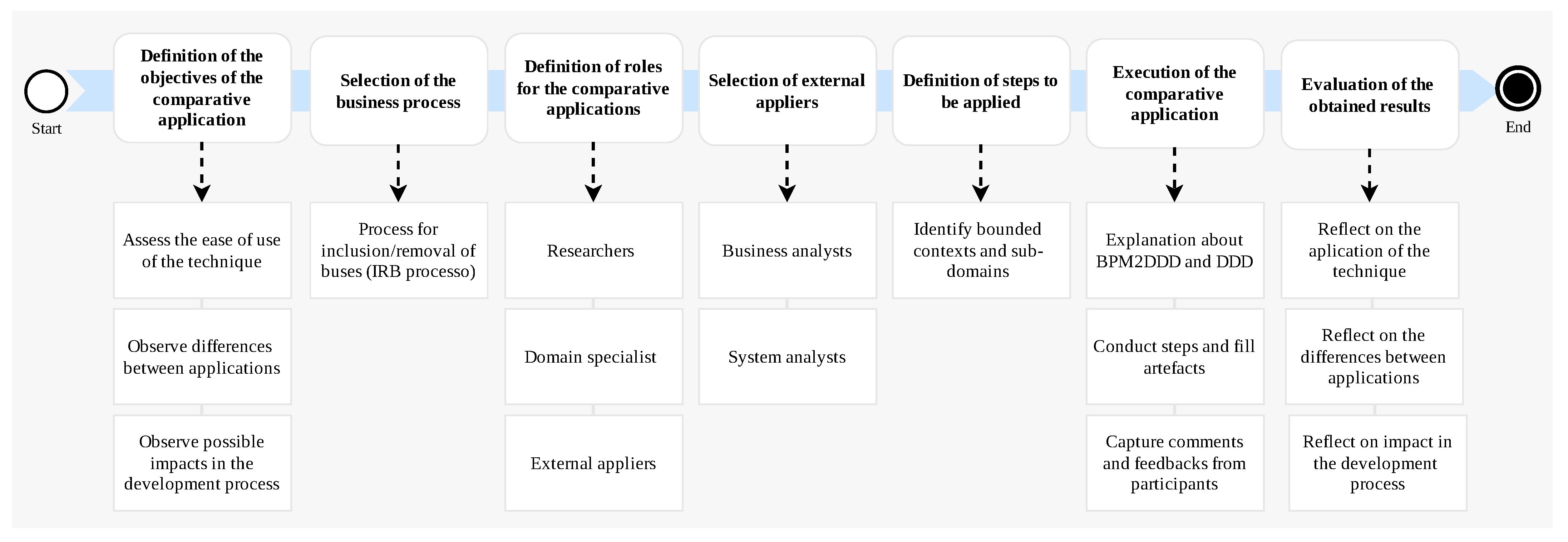
This section presents the phase 3 of the technique: review of the produced artefacts with domain specialists. Validating the context map is an important activity as it was projected to be used as a basis to implement the services and build the software solution. The main objective of the review/validation is to confirm if the bounded contexts, subdomains and other elements of the context map discovered by the technique make sense for the business and reflect the domain of the organisation.
We applied our approach to two business processes to derive context maps. The application in the IRB process was used as example for the different artefacts of the technique presented in Section 4. The second process is named “replacement of licensed vehicle” (RLV) and aims in replacing small vehicles involved in public transport, such as taxis and other modalities of permissions. The RLV process is way more complex than the IRB process presented above, and has been used to improve and validate the different activities of the technique. Those two processes have been chosen based on the scope defined for the ongoing software project.
The resulting context map is presented in Figure 21 in which we can observe the bounded contexts of internal and external domains. INMETRO (Instituto Nacional de Metrologia, Qualidade e Tecnologia) is the Brazilian National Institute of Metrology Standardization and Industrial Quality and DETRAN (Departamento Estadual de Trânsito) is responsible for driver’s licenses and vehicle registration. Regarding the relationship types, we used the following abbreviations: “CO” for conformist; “P” for partnership; “CS” for customer-supplier; “OHS” for open host service; “SW” for separate ways; and “PL” for published language.
The validation happened in two steps using the set of questions defined in Section 3.4. The first validation was conducted using the artefacts of the IRB process (presented in Section 4). After that the technique was applied in the RLV process and a new validation was performed. The domain experts confirmed the identification of bounded contexts and subdomains applying our technique except for one observation. This was related to two bounded contexts that belong to an external body: Payments and Processes (This is a bounded context identified during the second application of the technique in the RLV process). Further analysis revealed that this detail was not specified in the original BPMN model and as a result our technique could not capture these bounded contexts. This reinforced the importance of good process modelling and participation of domain experts. Additionally, domain experts have identified other business areas not involved in the business processes under consideration (IRB and RLV), and tried to introduce them in the context map under validation. This demonstrates that the insight provided by the context map can improve communication and discovery of relevant information both for the domain and for the systems that will support the business.
After domain experts review and approval of the context map, the development team proceeded to build services to realise the identified bounded contexts. Each bounded context has become a service. The operations of each service were defined using the SPReaD process [19].
The following services have been implemented and are in production: Permissions, Vehicle Inspection, Document Printing and Download Documents. The Layout Approval service has been deferred for future implementation. The Processes and Payments contexts represent existing systems. The contexts of Vehicle Records and Taximeter Certification represent bounded contexts that are external to the organisation, with no need to implement any service at the moment, but in the future there may be an integration between systems.
However, despite the initial expectation of deploying the new systems as independent microservices, in practice, their implementation followed some restrictions established by the project supervisors, where: (1) the application data should reside in a single shared database; and (2) the business logic should reside in the database using the stored procedures facility. To circumvent these restrictions and observing the bounded contexts defined by the technique, the development team adopted some actions, such as: (1) using database-specific schemas for each identified bounded context, creating a logical separation and facilitating a future extraction to a separate and de facto standalone database and microservice; and (2) building a thin application layer, containing only flow control, capable of being executed in multiple instances, each one triggering a set of stored procedures that represent the business logic for a given limited context.

5.2. A Comparison

In order to evaluate BPM2DDD we have conducted a comparative analysis of our approach. Comparative methods have been used for a long time in cross-cultural studies and social sciences to identify, analyse and explain similarities and differences across societies [44]. In our case we requested an independent team to apply the BPM2DDD approach to the IRB process and compare their results with ours. Figure 22 presents an overview of the methodology employed for the comparative analysis.
Our comparative application has three objectives: (1) to assess the ease of use of BPM2DDD approach by other people; (2) to observe differences between applications by different people; and (3) observe possible impacts of these differences in the development process, comparing the results obtained with the application presented in Section 4. The IRB process was selected for the comparative analysis because its results have been validated with domain specialists and used for the implementation of the actual system.
The following roles were defined: researcher, represented by one of the authors of this article and responsible for explaining the BPM2DDD approach, providing details on how to carry out its activities and observing the application; domain specialist, represented by a software architect from the development team and responsible for providing information about the organisation’s domain; and external appliers, represented by a business analyst and a systems analyst, both external to the project. The business analyst has experience in the analysis, mapping and optimisation of processes in a franchising company that has more than 100 stores throughout Brazil. The systems analyst works in the survey and analysis of requirements in a systems development company in the city of Natal/RN, which has more than 50 clients in its portfolio. They were selected based on their availability and their prior knowledge about BPMN. Unfortunately they were not familiar with DDD concepts and the domain of the organisation.
Due to time constraints the comparative application focused on the step Identify bounded contexts and subdomains because at the end of these it would be possible to compare the bounded contexts and subdomains identified with the context map presented in Section 4. Initially we have planned for a single session with three hours, in which the first 30 min were reserved for explaining the BPM2DDD process and the main concepts of DDD, and the last 30 min for collection of feedback from external appliers.
We used three questions in a questionnaire to assess the effectiveness of our technique: (1) Did the artefacts of BPM2DDD help in the discovery of domain information? (2) What is the biggest difficulty encountered in applying the BPM2DDD approach? and (3) What aspects of the BPM2DDD approach could be improved?
Initially the external participants were provided information about the BPM2DDD and DDD techniques. The different participants were introduced and the format of the comparative application was explained. The IRB process model was presented and explained by the domain specialist and the exercise started. After two hours the application was paused and a new session scheduled to be performed the following day. The first session completed the identification and classification of all actors and identification of all activities in the respective BPM2DDD artefacts. The second session lasted for three hours. In this session the bounded contexts and sub-domains have been identified in their respective artefacts. The session finished with the collection of feedback from the participants.
In both sessions the external participants performed the activities, producing the artefacts recommended by the technique, according to the researcher’s guidelines and details provided by the domain specialist. The results were then analysed based on the collected data, the researcher’s observations and the participant feedbacks.
Regarding objective (1) to assess the ease of use of the BPM2DDD technique by other people, we have noticed the following:
  • The external participants reported that the activities for direct extraction of information from the business process models with the support artefacts were carried out without difficulties. This indicates that supporting artefacts help appliers to make gradual progress in extracting information about the domain.
  • The external participants expressed their difficulties about how to perform some activities. These difficulties could have been reduced if they had a more in-depth knowledge of the BPM2DDD process. This indicates that more time should have been allocated for explaining the approach.
  • From the difference between the planned duration and actual time spent in the application, it is obvious that the BPM2DDD process with all its steps can be time consuming. This leads to the need to divide the application into different sessions. This also relates to the previous observation about spending more time in in-depth understanding of the BPM2DDD approach before using,
  • The greatest challenge reported is that activities that require domain knowledge demanded more time, even with a domain expert providing information.
  • Manual filling in the artefacts by the applicators, can be time consuming, especially if the process model has many elements. This indicates the need for support tools that help applicators to extract information from the BPMN model in an automated way.
Regarding objective (2) to observe differences between applications by different people, Figure 23 presents the bounded contexts and sub-domains identified by the researcher and by the external appliers, where we observe the following points:
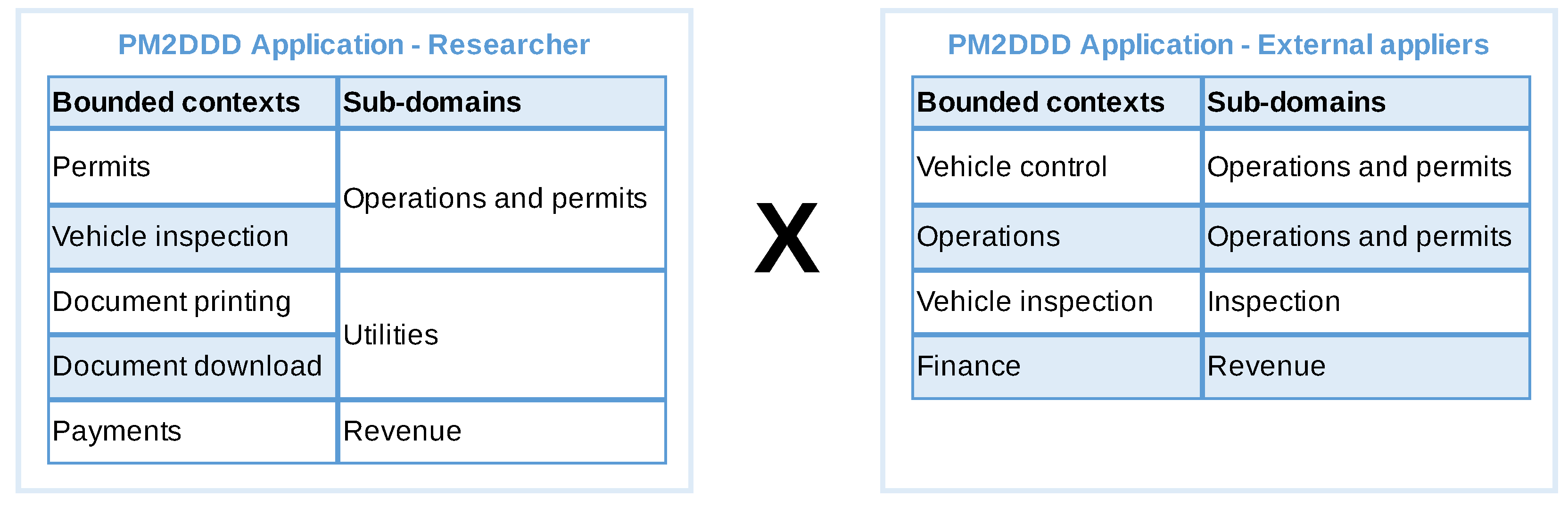
  • The external participants did not register generic contexts and subdomains such as Document printing. This indicates the need to address such DDD concepts in the explanation of the technique.
  • There was a difference between the terms used to describe the bounded contexts and subdomains, where the context of Permits has been identified as Operations or Vehicle Control; and Payments has been identified as Finance.
  • The bounded context Vehicle Inspection has been associated with the new sub-domain Inspection instead of the existing subdomain Operations and Permissions. This indicates a lack of more comprehensive knowledge about the organisation.
Figure 23. Comparison of the bounded context and sub-domains identified by our application and by external appliers.
Software 01 00018 g023
The differences in the produced artefacts emphasise the need for more in-depth knowledge about the domain of the organisation. This is reinforced by the feedback of the external participants, when they point out that the lack of a deeper knowledge about the organisation’s operations hampered the process of abstraction and generalisation of the elements identified in the support artefacts for the definition of business functions, bounded contexts and subdomains.
There was one observable difference. During this application, the independent participants’ interaction with the domain specialists was limited to two sessions, while in the application of Section 4 the analyst had constant contact with domain specialists during the entire execution of the technique. Furthermore, it is possible to infer that the lack of knowledge about the concepts of DDD was an important factor for the produced support artefacts.
Assuming that the context map generated by the technique will serve as a basis for defining the software services, it was possible to verify the following points in relation to the objective (3) to observe possible impacts of those differences in the development process:
  • Creating services based on the bounded contexts and subdomains identified in the comparative application could lead to building a system not aligned with the business, which could lead to more frequent changes in the software solution.
  • The separation of the bounded context Permits, observed in the first application, in Vehicle Control and Operations, observed in the comparative application, could lead to a greater effort to maintain separate representations for the same domain model.
  • Failure to discover the generic context of Document printing would lead to a late identification of this service, which could compromise the development flow and project schedule.
After analysing the data collected and the differences observed we believe that the BPM2DDD approach can be applied by other professionals. However, the current results are not deterministic, that is, the experience and knowledge of the applicators in relation to business processes, organisation domain and DDD are key factors that will influence the way information is transformed into the support artefacts of the technique, and how bounded contexts and subdomains are defined.

5.3. Discussion, Threats and Limitations

In this section we present a brief discussion over the results obtained with the BPM2DDD approach together with the main threats to the study and its limitation.
BPM2DDD presents a higher level of complexity compared to other approaches to service identification (discussed in Section 2.2), as it seeks to first explore the complexity of domain concepts, requiring more time to analysis by systems analysts. However, to the best of our knowledge, BPM2DDD is the first approach that provides a systematic way of identifying domains from business process models, and despite its extra complexity, this cost can be offset in a better quality of the resulting systems. This is highly consistent with the service design practices reported in [45] and with what is exposed in [5], since building services around business concepts, rather than technical concepts, makes systems more stable, in addition to improving responsiveness to business changes, making the technique presented in this work relevant. However, these quality aspects were not covered in this assessment and need to be explored in the future.
Our evaluation involved the application of the technique in a real project, although with the development team that was involved in its definition. This clearly points to implicit knowledge about DDD, the organisation domain and the technique itself, that contributed to the results obtained with its application. However, DDD has been proposed as an approach to build an “ubiquitous language shared by the team, developers, domain experts, and other participants” [1]. This require a deep understanding of the business, which BPM2DDD helps in acquiring by systematising its extraction from business process models. Our experience with the review of the context map with domain specialists also demonstrated the importance of having a context map as an effective communication tool. This encourages our technique.
The technique expects a BPMN model with some level of details about the business in order to be effectively applied. Although the construction of the BPMN model is out of scope of BPM2DDD, requiring this amount of detail restricts its usefulness, as only organisations with well-established practices for business process management would have this level of detail in their captured business process models.
We employed two independent participants to apply our approach and tried to assess if BPM2DDD can be implemented by different people who are not directly involved with the work. The comparative application has provided us the following insights: (a) the need of domain knowledge about the organisation; (b) the need of basic knowledge about BPMN; and (c) the need of knowledge about DDD; The main lesson learned is that, before future deployment of our approach, we should make sure to enable the appliers in these aspects.
When discussing the threats to our work we consider the guidance and references provided by Staron [46], in which four main types of threats to validity are presented: construct, internal, conclusion and external. Construct threats are those related to the research design. It is important to mention that BPM2DDD was developed and applied in the context of a real-world project, and thus a controlled experiment setting was not available from the start. In particular, we point to two main threats in this category. Mono-operation bias, as we worked with a single development team in a short period of time; and Interaction of different treatments, as the same team was also involved in the introduction of business process management practices and models to the organisation. These have been mitigated by bringing in external analysts in a comparative application of our approach, and by adopting extra care in separating the scope of the approach and their effects. Internal threats relate to the actions taken in the research. In particular, one could argue that we have the threat of biased selection of subjects (which can be slightly related to the threats of history and maturation) as the domain specialists were involved in the project since its start and evolved together with the team in the use of business process models. Unfortunately this is outside our control as we have been brought into a live project and thus have to be bounded by the different constraints that this impose. Regarding conclusion threats we recognise the threat of Finding a relationship when there it not one about the possible improvement in the quality of the produced context map. It could be argued that a rigorous comparison with other approaches for establishing context maps is needed. However, no such systematic approach exists which does not allow us to compare our approach. Regarding external threats, we have identified a main threat to be of multiple treatment interference as there is an overlap within the development team in the adoption of new techniques to support the capture of business processes (BoAT [16]) and BPM2DDD. Again, the mitigation approach we adopted was to bring in external analysts to apply the BPM2DDD process as part of the evaluation.

6. Conclusions

This article presented BPM2DDD, a systematic approach for the definition of domain-driven design artefacts, supporting the identification of bounded contexts and their relationships captured in context maps from business process models. The main contribution of our article lies in articulating the BPM2DDD process. To the best of our knowledge, this is the first approach with a systematic step-by-step directions on how to create context maps from BPMN models. There has been mentions about usage of DDD and creation of context maps, but with no concrete instructions, and purely dependent on individual skills and disciplines.
Our approach receives as input a BPMN model, which is then reviewed against a number of requirements in terms of the elements present in the model. This is done so the generated context map reflects the business reality as close as possible. This can also be used by BPM teams when evaluating their own business process.
We have applied the technique into a real project, producing a context map that has been validated by domain specialists, and then used by a software development team to implement a number of services as part of their solution. We have also performed a comparative application with analysts that are external to the software development team. Although this was not a rigorous evaluation, it provided some initial insight that will be taken on-board as we move forward and look for its application in other business processes and organisations.
The main limitation of the technique is its complexity and required previous knowledge about DDD and the organisation domain. This is true to any project that employs DDD, and indicate the need for some specific training before the technique can be applied. Nevertheless, BPM2DDD still helped analysts in extracting information from business processes, which can then be used in discussions with domain specialists. Another difficulty encountered with the technique is the filling of its interim artefacts when the input BPMN has huge number of elements. Thus we intent to address this in our future work. We plan to work on the relationship between the interim artefacts, so they can be captured as a meta-model that can be used to provide some automation in the extraction of information from BPMN source files. Another future work involves the integration of our approach with some of the existing tools for automatic generation of microservices from DDD artefacts, such as the context mapper tool [31] or LEMMA models [32]. Such integration would require the use of the tools metamodel to represent the DDD artefacts.

Author Contributions

Conceptualization, C.E.d.S. and E.L.G.; methodology, C.E.d.S. and E.L.G.; software, E.L.G.; validation, C.E.d.S. and S.S.B.; formal analysis, E.L.G.; investigation, C.E.d.S. and E.L.G.; resources, C.E.d.S. and E.L.G.; data curation, E.L.G.; writing—original draft preparation, E.L.G. and C.E.d.S.; writing—review and editing, C.E.d.S. and S.S.B.; visualization, E.L.G. and C.E.d.S.; supervision, C.E.d.S.; project administration, C.E.d.S. All authors have read and agreed to the published version of the manuscript.

Funding

This research received no external funding.

Institutional Review Board Statement

The study was conducted in the scope of the professional master programme in information technology of the Metropolis Digital Institute of the Federal University of Rio Grande do Norte. Formal ethical approval was deemed not necessary, nevertheless the study counted with internal approval of the programme and the participant institution.

Informed Consent Statement

Informed consent was obtained from all subjects involved in the study.

Data Availability Statement

Not applicable.

Acknowledgments

The authors would like to thanks all the participant of the comparative analysis that kindly volunteered their valuable time for this exercise.

Conflicts of Interest

The authors declare no conflict of interest.

Abbreviations

The following abbreviations are used in this manuscript:
BDMBusiness Data Model
BPMBusiness Process Management
BPMNBusiness Process Model and Notation
DDDDomain-Driven Design
IRBInclusion/Removal of Buses
ITInformation Technology
MSAMicroservice Architecture
OUOrganisational Unit
WFMWorkflow Management

Appendix A

This appendix presents the general structure of all artefacts used by the technique and explained throughout the text.
Figure A1. General structure of all template for artefacts used by the BPM2DDD technique.
Software 01 00018 g0a1

References

  1. Evans, E.; Fowler, M. Domain-Driven Design: Tackling Complexity in the Heart of Software; Addison-Wesley: Boston, MA, USA, 2004. [Google Scholar]
  2. Rademacher, F.; Sachweh, S.; Zündorf, A. Deriving Microservice Code from Underspecified Domain Models Using DevOps-Enabled Modeling Languages and Model Transformations. In Proceedings of the 2020 46th Euromicro Conference on Software Engineering and Advanced Applications (SEAA), Portoroz, Slovenia, 26–28 August 2020; pp. 229–236. [Google Scholar] [CrossRef]
  3. Lewis, J.; Fowler, M. Microservices. 2019. Available online: https://martinfowler.com/articles/microservices.html (accessed on 2 September 2022).
  4. Alpers, S.; Becker, C.; Oberweis, A.; Schuster, T. Microservice Based Tool Support for Business Process Modelling. In Proceedings of the 2015 IEEE 19th International Enterprise Distributed Object Computing Workshop, Adelaide, Australia, 21–25 September 2015; pp. 71–78. [Google Scholar] [CrossRef]
  5. Newman, S. Building Microservices: Designing Fine-Grained Systems, 1st ed.; O’Reilly Media: Sebastopol, CA, USA, 2015; p. 280. [Google Scholar]
  6. Amiri, M.J. Object-Aware Identification of Microservices. In Proceedings of the 2018 IEEE International Conference on Services Computing (SCC), San Francisco, CA, USA, 2–7 July 2018; pp. 253–256. [Google Scholar] [CrossRef]
  7. Cerny, T.; Donahoo, M.J.; Pechanec, J. Disambiguation and Comparison of SOA, Microservices and Self-Contained Systems. In Proceedings of the International Conference on Research in Adaptive and Convergent Systems RACS ’17, Krakow Poland, 20–23 September 2017; ACM: New York, NY, USA, 2017; pp. 228–235. [Google Scholar] [CrossRef]
  8. Huergo, R.; Pires, P.; Delicato, F.; Costa, B.; Batista, T. A Systematic Survey of Service Identification Methods. Serv. Oriented Comput. Appl. 2014, 8, 199–219. [Google Scholar] [CrossRef]
  9. Di Francesco, P.; Lago, P.; Malavolta, I. Migrating Towards Microservice Architectures: An Industrial Survey. In Proceedings of the 2018 IEEE International Conference on Software Architecture (ICSA), Seattle, WA, USA, 30 April–4 May 2018; pp. 2900–2909. [Google Scholar] [CrossRef]
  10. Singjai, A.; Zdun, U.; Zimmermann, O. Practitioner Views on the Interrelation of Microservice APIs and Domain-Driven Design: A Grey Literature Study Based on Grounded Theory. In Proceedings of the 2021 IEEE 18th International Conference on Software Architecture (ICSA), Stuttgart, Germany, 22–26 March 2021; pp. 25–35. [Google Scholar] [CrossRef]
  11. Waseem, M.; Liang, P.; Shahin, M.; Di Salle, A.; Márquez, G. Design, Monitoring, and Testing of Microservices Systems: The Practitioners’ Perspective. J. Syst. Softw. 2021, 182, 111061. [Google Scholar] [CrossRef]
  12. Hippchen, B.; Schneider, M.; Giessler, P.; Abeck, S. Systematic Application of Domain-Driven Design for a Business-Driven Microservice Architecture. Int. J. Adv. Softw. 2019, 12, 343–355. [Google Scholar]
  13. Millett, S.; Tune, N. Patterns, Principles, and Practices of Domain-Driven Design; Wiley: Hoboken, NJ, USA, 2015. [Google Scholar]
  14. Richardson, C. Microservices Patterns: With Examples in Java; Manning: Shelter Island, NY, USA, 2019. [Google Scholar]
  15. Shenglin, L.; Qinghui, R.; Chen, C. Application of DDD Theory in Analysis and Design of Equipment Maintenance System. In Proceedings of the 2019 IEEE Symposium Series on Computational Intelligence (SSCI), Xiamen, China, 6–9 December 2019; pp. 3275–3280. [Google Scholar] [CrossRef]
  16. da Silva, C.E.; Medeiros, L.; Justino, Y.; Gomes, E. A Box Analogy Technique (BoAT) for Agile-based Modelling of Business Processes. In Proceedings of the 2022 IEEE 30th International Requirements Engineering Conference (RE), Melbourne, Australia, 15–19 August 2022. [Google Scholar]
  17. Cardoso, E.C.S.; Almeida, J.P.A.; Guizzardi, G. Requirements Engineering Based on Business Process Models: A Case Study. In Proceedings of the 2009 13th Enterprise Distributed Object Computing Conference Workshops, Auckland, New Zealand, 1–4 September 2009; pp. 320–327. [Google Scholar] [CrossRef]
  18. Unger, A.; Spinola, M.; Pessôa, M. Requirements Engineering Approaches to Derive Enterprise Information Systems from Business Process Management: A Systematic Literature Review. In Requirements Engineering Und Business Process Management (REBPM), Proceedings of the Workshops at Modellierung Braunschweig, Germany, 21 February 2018; Schaefer, I., Cleophas, L., Felderer, M., Eds.; 2018; pp. 261–271. Available online: http://ceur-ws.org/Vol-2060/rebpm6.pdf (accessed on 2 September 2022).
  19. da Silva, C.E.; Justino, Y.d.L.; Adachi, E. SPReaD: Service-Oriented Process for Reengineering and DevOps. Serv. Oriented Comput. Appl. 2021, 16, 1–16. [Google Scholar] [CrossRef]
  20. Van Der Aalst, W.M. Business Process Management: A Comprehensive Survey. ISRN Softw. Eng. 2013, 2013, 1–37. [Google Scholar] [CrossRef]
  21. Dumas, M.; La Rosa, M.; Mendling, J.; Reijers, H.A. Fundamentals of Business Process Management; Springer: Berlin/Heidelberg, Germany, 2018. [Google Scholar] [CrossRef]
  22. Benedict, T.; Bilodeau, N.; Vitkus, P.; Powell, E.; Morris, D.; Scarsig, M.; Lee, D.; Field, G.; Lohr, T.; Saxena, R.; et al. BPM CBOK Version 3.0: Guide to the Business Process Management Common Body of Knowledge, 3rd ed.; CreateSpace/ABPMP—Association of Business Process Management Professionals: Pensacola, FL, USA, 2013. [Google Scholar]
  23. OMG. Business Process Model and Notation (BPMN), Version 2.0.2; Technical Report Formal/2013-12-09; Object Management Group: Needham, MA, USA, 2013. [Google Scholar]
  24. Vernon, V. Implementing Domain-Driven Design; Pearson Education: London, UK, 2013. [Google Scholar]
  25. Lai, H.; Peng, R.; Ni, Y. A Collaborative Method for Business Process Oriented Requirements Acquisition and Refining. In Proceedings of the 2014 International Conference on Software and System Process, ICSSP, Nanjing, China, 26–28 May 2014; ACM: New York, NY, USA, 2014; pp. 84–93. [Google Scholar] [CrossRef]
  26. Götz, B.; Schel, D.; Bauer, D.; Henkel, C.; Einberger, P.; Bauernhansl, T. Challenges of Production Microservices. Procedia CIRP 2018, 67, 167–172. [Google Scholar] [CrossRef]
  27. Costa, I.C.; de Oliveira, J.M.P. GO4SOA: Goal-oriented Modeling for SOA. In Proceedings of the 12th International Conference on Web Information Systems and Technologies—Volume 1: WEBIST, INSTICC, SciTePress, Rome, Italy, 23–25 April 2016; pp. 247–254. [Google Scholar] [CrossRef]
  28. Amiri, M.J.; Parsa, S.; Lajevardi, A. Multifaceted Service Identification: Process, Requirement and Data. Comput. Sci. Inf. Syst. 2016, 13, 335–358. [Google Scholar] [CrossRef]
  29. Daoud, M.; el Mezouari, A.; Faci, N.; Benslimane, D.; Maamar, Z.; Fazziki, A. Automatic Microservices Identification from a Set of Business Processes. In Proceedings of the Smart Applications and Data Analysis. SADASC 2020, Communications in Computer and Information Science, Marrakesh, Morocco, 25–26 June 2020; Volume 1207, pp. 299–315. [Google Scholar]
  30. Landre, E.; Wesenberg, H.; Rønneberg, H. Architectural Improvement by Use of Strategic Level Domain-Driven Design. In Proceedings of the Companion to the 21st ACM SIGPLAN Symposium on Object-Oriented Programming Systems, Languages, and Applications, OOPSLA ’06, Portland, OR, USA, 22–26 October 2006; Association for Computing Machinery: New York, NY, USA, 2006; pp. 809–814. [Google Scholar] [CrossRef]
  31. Kapferer, S.; Zimmermann, O. Domain-Driven Architecture Modeling and Rapid Prototyping with Context Mapper. In Model-Driven Engineering and Software Development, Proceedings of the 8th International Conference, MODELSWARD 2020, Valletta, Malta, 25–27 February 2020; Hammoudi, S., Pires, L.F., Selić, B., Eds.; Springer International Publishing: Cham, Switzerland, 2021; Volume 1361, pp. 250–272. [Google Scholar] [CrossRef]
  32. Giallorenzo, S.; Montesi, F.; Peressotti, M.; Rademacher, F. Model-Driven Generation of Microservice Interfaces: From LEMMA Domain Models to Jolie APIs. In Coordination Models and Languages, Proceedings of the 24th IFIP WG 6.1 International Conference, COORDINATION 2022, Lucca, Italy, 13–17 June 2022; ter Beek, M.H., Sirjani, M., Eds.; Springer International Publishing: Cham, Switzerland, 2022; Volume 13271, pp. 223–240. [Google Scholar] [CrossRef]
  33. Singjai, A.; Zdun, U.; Zimmermann, O.; Pautasso, C. Patterns on Deriving APIs and Their Endpoints from Domain Models. In Proceedings of the 26th European Conference on Pattern Languages of Programs, EuroPLoP’21, Graz, Austria, 7–11 June 2021; Association for Computing Machinery: New York, NY, USA, 2021; pp. 1–15. [Google Scholar] [CrossRef]
  34. Wesenberg, H.; Landre, E.; Rønneberg, H. Using Domain-Driven Design to Evaluate Commercial off-the-Shelf Software. In Proceedings of the Companion to the 21st ACM SIGPLAN Symposium on Object-oriented Programming Systems, Languages, and Applications, OOPSLA ’06, Portland, OR, USA, 22–26 October 2006; Association for Computing Machinery: New York, NY, USA, 2006; pp. 824–829. [Google Scholar] [CrossRef]
  35. Cabrera, E.; Cárdenas, P.; Cedillo, P.; Pesántez-Cabrera, P. Towards a Methodology for Creating Internet of Things (IoT) Applications Based on Microservices. In Proceedings of the 2020 IEEE International Conference on Services Computing (SCC), Beijing, China, 7–11 November 2020; pp. 472–474. [Google Scholar] [CrossRef]
  36. Santos, N.; Pereira, J.; Ferreira, N.; Machado, R.J. Modeling in Agile Software Development: Decomposing Use Cases towards Logical Architecture Design. In Product-Focused Software Process Improvement, Proceedings of the 19th International Conference, PROFES 2018, Wolfsburg, Germany, 28–30 November 2018; Kuhrmann, M., Schneider, K., Pfahl, D., Amasaki, S., Ciolkowski, M., Hebig, R., Tell, P., Klünder, J., Küpper, S., Eds.; Springer International Publishing: Cham, Switzerland, 2018; pp. 396–408. [Google Scholar]
  37. Santos, N.; Salgado, C.E.; Morais, F.; Melo, M.; Silva, S.; Martins, R.; Pereira, M.; Rodrigues, H.; Machado, R.J.; Ferreira, N.; et al. A Logical Architecture Design Method for Microservices Architectures. In Proceedings of the 13th European Conference on Software Architecture—Volume 2, ECSA ’19, Paris, France, 9–13 September 2019; Association for Computing Machinery: New York, NY, USA, 2019; pp. 145–151. [Google Scholar] [CrossRef]
  38. Gysel, M.; Kölbener, L.; Giersche, W.; Zimmermann, O. Service Cutter: A Systematic Approach to Service Decomposition. In Service-Oriented and Cloud Computing, Proceedings of the 5th IFIP WG 2.14 European Conference, ESOCC 2016, Vienna, Austria, 5–7 September 2016; Aiello, M., Johnsen, E.B., Dustdar, S., Georgievski, I., Eds.; Springer International Publishing: Cham, Switzerland, 2016; pp. 185–200. [Google Scholar]
  39. Tyszberowicz, S.; Heinrich, R.; Liu, B.; Liu, Z. Identifying Microservices Using Functional Decomposition. In Dependable Software Engineering. Theories, Tools, and Applications, Proceedings of the 4th International Symposium, SETTA 2018, Beijing, China, 4–6 September 2018; Feng, X., Muller-Olm, M., Yang, Z., Eds.; Springer International Publishing: Cham, Switzerland, 2018; pp. 50–65. [Google Scholar]
  40. Hippchen, B.; Giessler, P.; Steinegger, R.H.; Schneider, M.; Abeck, S. Designing Microservice-Based Applications by Using a Domain-Driven Design Approach. Int. J. Adv. Softw. 2017, 10, 432–445. [Google Scholar]
  41. Baresi, L.; Garriga, M.; De Renzis, A. Microservices Identification through Interface Analysis. In Service-Oriented and Cloud Computing, Proceedings of the 6th IFIP WG 2.14 European Conference, ESOCC 2017, Oslo, Norway, 27–29 September 2017; De Paoli, F., Schulte, S., Broch Johnsen, E., Eds.; Springer International Publishing: Cham, Switzerland, 2017; pp. 19–33. [Google Scholar]
  42. Mazlami, G.; Cito, J.; Leitner, P. Extraction of Microservices from Monolithic Software Architectures. In Proceedings of the 2017 IEEE International Conference on Web Services (ICWS), Honolulu, HI, USA, 25–30 June 2017; pp. 524–531. [Google Scholar] [CrossRef]
  43. De Alwis, A.A.C.; Barros, A.; Polyvyanyy, A.; Fidge, C. Function-Splitting Heuristics for Discovery of Microservices in Enterprise Systems. In Service-Oriented Computing, Proceedings of the 16th International Conference, ICSOC 2018, Hangzhou, China, 12–15 November 2018; Pahl, C., Vukovic, M., Yin, J., Yu, Q., Eds.; Springer International Publishing: Cham, Switzerland, 2018; pp. 37–53. [Google Scholar]
  44. Boeije, H. A Purposeful Approach to the Constant Comparative Method in the Analysis of Qualitative Interviews. Qual. Quant. 2002, 36, 391–409. [Google Scholar] [CrossRef]
  45. Garriga, M. Towards a Taxonomy of Microservices Architectures. In Software Engineering and Formal Methods, Proceedings of the SEFM 2017 Collocated Workshops: DataMod, FAACS, MSE, CoSim-CPS, and FOCLASA, Trento, Italy, 4–5 September 2017; Cerone, A., Roveri, M., Eds.; Springer International Publishing: Cham, Switzerland, 2018; pp. 203–218. [Google Scholar] [CrossRef]
  46. Staron, M. Action Research in Software Engineering: Theory and Applications, 1st ed.; Springer International Publishing: Cham, Switzerland, 2020. [Google Scholar] [CrossRef]
Figure 1. A sub-set of the main elements defined by the BPMN specification [23].
Software 01 00018 g001
Figure 2. Graphical representation of the methodology employed in the development of BPM2DDD.
Software 01 00018 g002
Figure 3. BPMN description of the main steps of the BPM2DDD approach.
Software 01 00018 g003
Figure 4. BPMN description of the steps of the Identify bounded context and subdomains step.
Software 01 00018 g004
Figure 5. BPMN model of the process for inclusion/removal of bus after refinement.
Software 01 00018 g005
Figure 6. Extracting activities and actors from the bpmn model into the artefact A10. Activities.
Software 01 00018 g006
Figure 7. Populating the artefact A2. BPMN-CM Elements with actors and their natures (internal/external).
Software 01 00018 g007
Figure 8. Snapshot of artefact A2. BPMN-CM Elements with actors, their natures (internal/external) and identification of consumers/providers.
Software 01 00018 g008
Figure 9. Grouping of activities from artefact A10. Activities into artefact A2. BPMN-CM Elements based on their similarity of functionality.
Software 01 00018 g009
Figure 10. Example of artefact A2. BPMN-CM Elements with identified business functions and bounded contexts.
Software 01 00018 g010
Figure 11. Example of artefact A2. BPMN-CM Elements with identified sub-domains.
Software 01 00018 g011
Figure 12. Example of artefact A2. BPMN-CM Elements being used to isolate the identified sub-domains into the artefact A3. Sub-domains.
Software 01 00018 g012
Figure 13. Extracting related activities based on BPMN “groups” into the artefact A4. Related activities, which is then complemented with the respective bounded contexts from artefact A2. BPMN-CM Elements.
Software 01 00018 g013
Figure 14. Populating the artefact A5. Communication events based on the BPMN model message flows and communication events.
Software 01 00018 g014
Figure 15. Populating the artefact A6. Business objects based on the data objects of the BPMN model, their use by the different activities and the bounded contexts identified in artefact A2. BPMN-CM Elements.
Software 01 00018 g015
Figure 16. Identifying relationships for artefact A7 based on combinatorial of bounded context identified in artefact A4. Related activities.
Software 01 00018 g016
Figure 17. Identifying relationships for artefact A7 based on message flows and communication events (A5).
Software 01 00018 g017
Figure 18. Identifying relationships for artefact A7 based on business objects identified in A6.
Software 01 00018 g018
Figure 19. Example of the artefact A7. Relationships after including directions and types for all participants of the identified relationships.
Software 01 00018 g019
Figure 20. Generated context map based on the artefacts produced by the BPM2DDD technique.
Software 01 00018 g020
Figure 21. Resulting context map after application of the BPM2DDD technique in two business processes.
Software 01 00018 g021
Figure 22. An overview of the method employed for the comparative application of the technique.
Software 01 00018 g022
Publisher’s Note: MDPI stays neutral with regard to jurisdictional claims in published maps and institutional affiliations.

