2.1. Nickel Effects on the Transformation Behavior
Due to the similarity in principal properties, nickel and iron form a substitutional solid solution when mixed together. The Fe–Ni binary-phase diagram, which principally represents the possible phase formation in steels alloyed with nickel indicates the stabilization of the austenitic (fcc) phase in Ni-alloyed steel towards lower temperatures (
Figure 1a). Two-phase ferritic-austenitic microstructures exist at room temperature when the Ni contents exceed approximately 15 wt.%. Bainite or martensite formation is promoted upon down-cooling as a result of the decreasing transformation temperature with increasing nickel content. Above 6 wt.% Ni content, diffusion-controlled transformation processes are fully suppressed, resulting in martensite transformation. In the presence of carbon, phase fields are somewhat shifted but, principally, the effects of nickel on the transformation behavior remain similar. Experimentally determined A
c1 and A
c3 temperatures are shown in
Figure 1b as a function of the nickel content in a 0.1 wt.% carbon-containing steel [
4]. The influence of nickel is obviously stronger on the A
c3 temperature than on the A
c1 temperature. These temperatures are important with regard to re-austenitizing and tempering treatments.
The activation energy for the diffusion of nickel atoms in iron is rather high, so that the diffusion coefficient of nickel is generally low and comparable to the self-diffusion of iron [
5]. Therefore, equilibration of concentration variations can be achieved only during long holding times at high temperature. However, nickel diffuses faster in bcc iron than in fcc iron. This difference causes a hysteresis in the transformation behavior between cooling and heating cycles and becomes pronounced for Ni contents above approximately 5%. Martensite transformation commences during down-cooling when passing the M
s (martensite-start) temperature. Before reaching M
f (martensite-finish) temperature, bcc and fcc phases coexist; however, the nickel concentration in either phase can be assumed to be nearly equal due to the very slow diffusion. However, when reheating above the
γs (austenite-start) temperature into the region of coexisting fcc and bcc phases, nickel can partition into austenite, provided the holding time is sufficiently long. Such nickel-enriched crystallites can finally survive as metastable retained austenite phases when cooling back to ambient temperature. In technical steel alloys, carbon and manganese also partition to these austenite islands providing additional stabilization. The retained austenite fraction present in carbon steels after heat treatment enables a transformation-induced plasticity (TRIP) effect and makes an important contribution to enhanced formability and low temperature toughness, as will be discussed later (see
Section 2.6).
In the high-temperature range, the Fe–Ni binary alloy comprises a peritectic reaction such as the Fe–C binary alloy. Solidification from the liquid phase can proceed along various phase transformation scenarios (
Figure 1c) [
6]. For lower nickel additions (<3.4 wt.%), with a respectively low carbon content, solidification occurs entirely as
δ-ferrite, subsequently transforming to austenite. The final transformation starts by nucleation of α-ferrite at the austenite grain boundaries and subsequent growth. The size of these ferrite grains depends on the degree of undercooling controlled by the Ni content and the cooling rate. At higher nickel content the austenite phase either transforms by nucleation of grain boundary ferrite or by diffusionless transformation into martensite below the M
s temperature. In the latter case, the boundaries of the prior columnar austenite grains will be maintained with the martensite substructure developing inside this boundary. Especially after direct solidification from liquid to austenite, impurities such as sulfur and phosphorous segregated to the austenite grain boundary also decorate the prior austenite grain boundary in the final martensitic microstructure. This is not the case when ferrite nucleation and growth erase the prior austenite boundaries in steels with lower nickel content. Additionally, dilatational stresses originating from the martensite transformation act on the prior austenite grain boundaries. The resulting embrittlement of such boundaries can cause intergranular cracking and is relevant to the performance of higher-nickel alloyed steels in as-cast condition as well as after fusion welding. The removal of this detrimental effect requires dedicated heat treatment.
Figure 1.
(
a) Phase diagram of binary Fe–Ni alloy (Composed from data in [
7,
8,
9]); (
b) influence of nickel alloying on the transformation temperature of 0.1 wt.% carbon steel upon re-austenitizing using data from [
4]; (
c) solidification scenarios for carbon steels with increasing nickel content (Reprinted from Ref. [
6]).
2.2. Nickel Interaction with Carbon
Nickel can form a carbide species with the composition Ni
3C. The decomposition of the metastable Ni
3C carbide into Ni and C starts at a temperature of around 465 °C and is accompanied by a thermal effect −ΔH ≈ 10 kJ/mol [
10]. However, due to its low affinity to carbon, nickel carbide does not form in steel. In ternary Fe–C–Ni alloys, the diffusivities of nickel and carbon are mutually enhanced. Small amounts of nickel dissolved in iron carbide (cementite) facilitate its decomposition, which results in graphite formation during long holding periods at high pearlite temperature. The graphite-promoting effect of nickel is prominent in cast iron alloys but not relevant to carbon steels. As early as the year 1924 it had been reported that nickel lowers the pearlite formation temperature and lowers the eutectoid carbon content [
11]. Quantitatively, the addition of 1 wt.% Ni reduces the pearlite formation temperature by about 15 K and lowers the eutectoid carbon content by around 0.04 wt.% [
12]. However, nickel does not refine the pearlite lamellar structure beyond that provoked by the undercooling effect [
13]. Accordingly, nickel alloying to low carbon steel increases the phase fraction of pearlite, as was observed for a 0.17 wt.%C steel in which the pearlite phase fraction linearly increased from 0.2 to 0.3 when adding up to 3 wt.% Ni [
14].
Like silicon, nickel raises the activity of carbon in steel, which also affects the solubility of micro-alloy carbides at low level. The results of Eckstein et al. [
15] indicate that the dissolution temperature of niobium carbo-nitride is increased by only about 5 K when adding 0.5 wt.%Ni to carbon steel. Manganese, molybdenum, and chromium on the contrary reduce the niobium carbonitride dissolution temperature by a similar magnitude at 0.5 wt.% addition levels. Sharma et al. [
16] derived interaction parameters for nickel and other common alloying elements allowing the correction of the niobium solubility product. However, as the magnitude of the nickel effect on the solubility of micro-alloy carbides in relevant steel compositions is rather small, it has no significant consequences regarding practical soaking treatments. On the other hand, an enhanced carbon activity by nickel could promote micro-alloy precipitation at lower austenite temperature.
2.3. Transformation Kinetics and Hardenability of Nickel Alloyed Carbon Steels
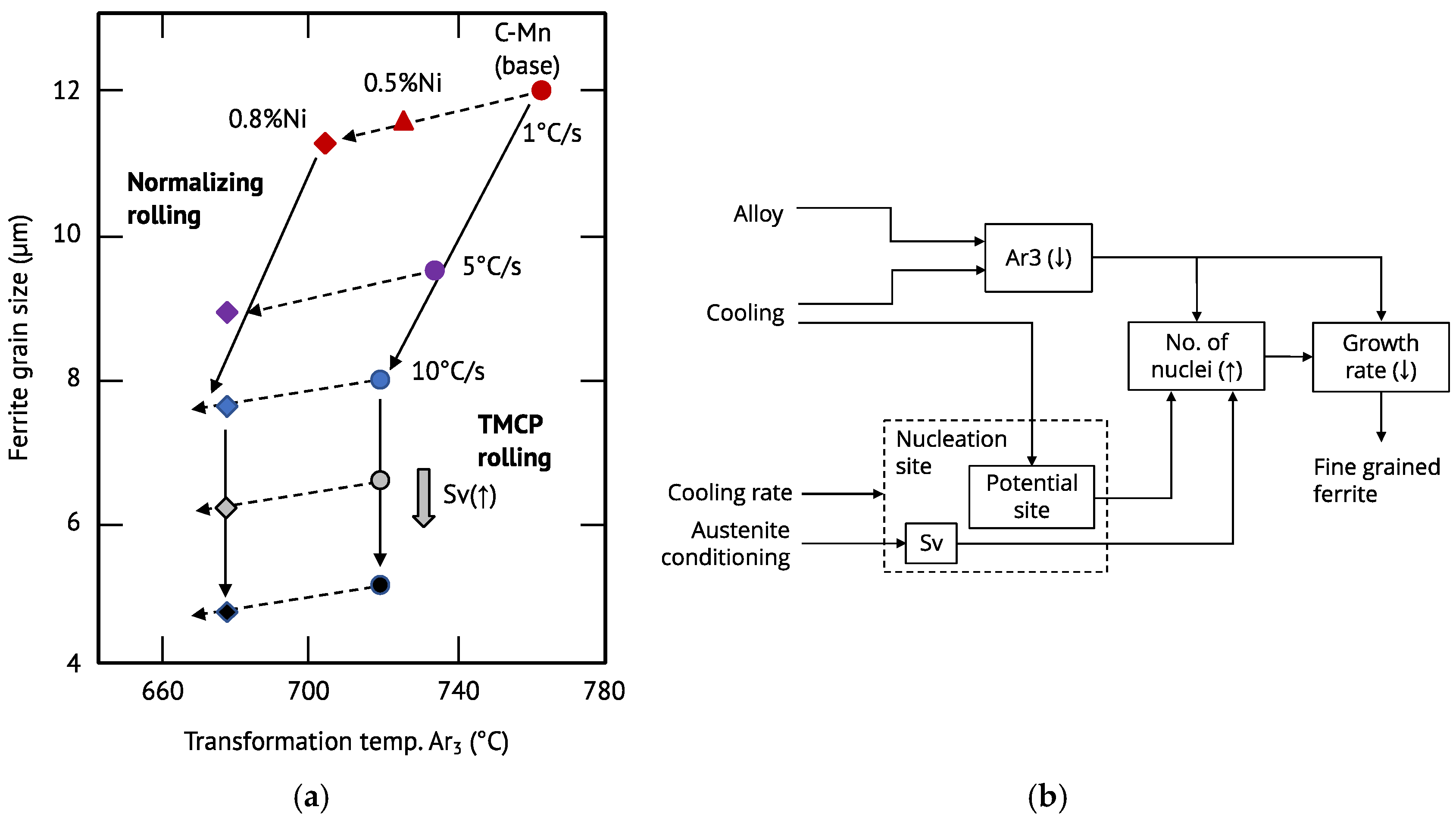
The significant extension of the austenite phase field by nickel alloying in combination with its low diffusivity in the austenite lattice delays the austenite-to-ferrite transformation towards lower temperature or extended times. The resulting undercooling causes an increased ferrite nucleation rate and decreased ferrite growth rate leading to a general refinement of the ferrite microstructure. However, Kosazu [
17] has reported that the refining effect of nickel alone and under slow cooling rates is rather modest. Accelerated cooling from temperatures above A
r3 induces a similar undercooling effect and refinement mechanisms. The nickel alloy effect in combination with that of accelerated cooling can thereby act in synergy (
Figure 2a) [
17,
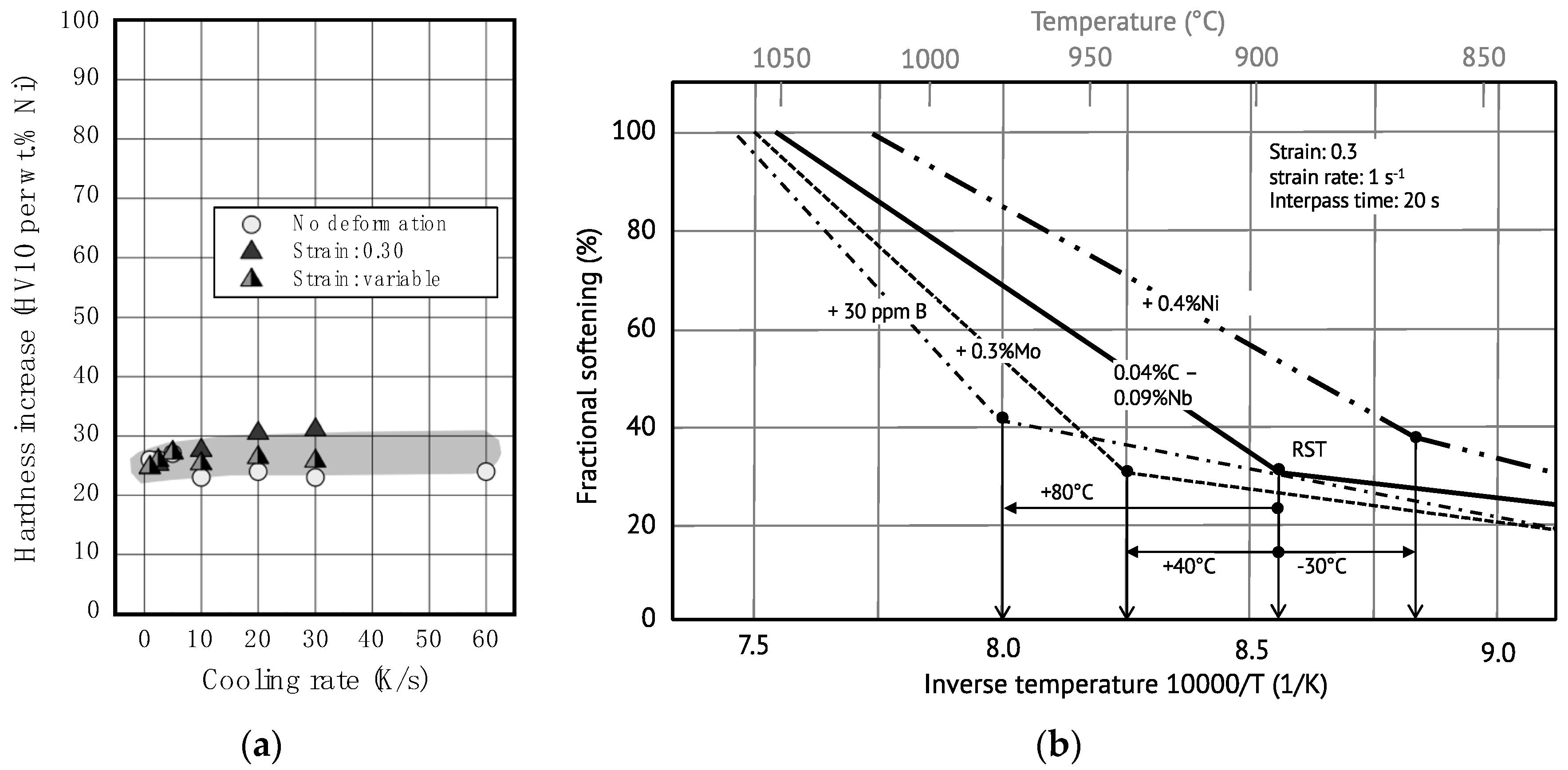
18]. The excessive application of both parameters, i.e., Ni alloying and accelerated cooling might cause, however, the formation of undesirable coarse bainite structures during the transformation from equiaxed austenite. This is related to the circumstance that only preferential austenite grain boundaries can nucleate ferrite grains. Enhancing the heterogeneity in austenite by controlled deformation below the recrystallization temperature, however, provides a much larger number of ferrite nucleation sites, avoiding the formation of coarse-grained bainitic features (
Figure 2b).
These austenite heterogeneities represented by total grain boundary area and intergranular deformation bands are quantitatively described by the Sv parameter, i.e., effective grain boundary area per unit volume. Controlled austenite deformation in combination with accelerated cooling produces very fine-grained ferrite, resulting in high yield strength and low ductile-to-brittle transition temperature upon impact loading. However, particularly in heavy-gauged products, it is often not possible to achieve a high degree of controlled deformation in the central area. Furthermore, the achievable cooling rates are comparably low. Thus, nickel alloying can effectively help to improve mechanical properties in sections where such inferior processing conditions prevail.
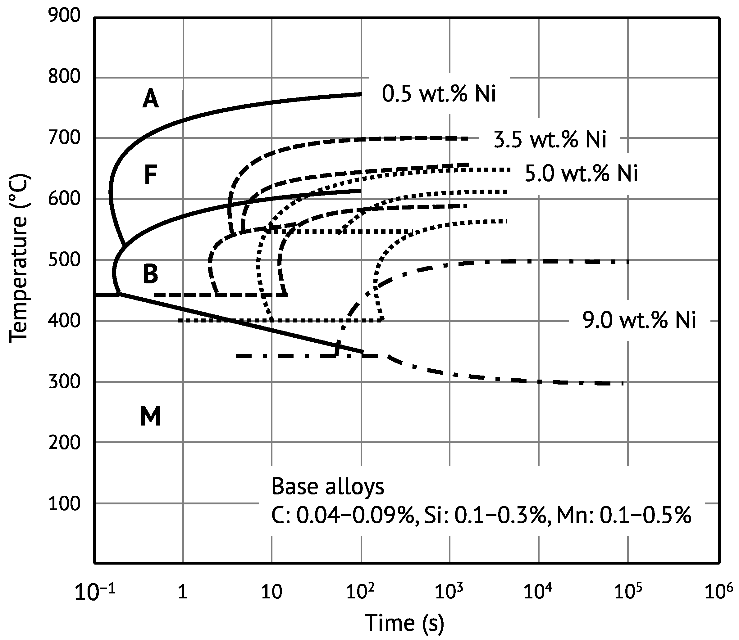
With increasing nickel alloy content, pearlite and subsequently bainite transformation is progressively suppressed, finally leading to full martensite formation. The maximum transformation rate for combined pearlite and bainite formation decreases with increasing nickel content. In steels with more than 3 wt.% Ni it becomes therefore difficult to separate pearlite from bainite formation. The influence of increasing nickel alloy content up to 9 wt.% Ni on the transformation behavior of low-carbon structural steels is exemplarily demonstrated by the CCT curves in
Figure 3.
The martensite-start (M
s) temperature decreases with 17–19 K per weight percent nickel added [
20]. It is commonly understood that martensite transformation is an athermal process (i.e., it does not require thermal activation) that cannot be suppressed. However, it has been known for a long time that isothermal formation of martensite is also feasible. Borgenstam and Hillert [
21] have reviewed these early studies regarding the kinetics of isothermal martensite transformation. The activation energy was estimated to be in the range of 7 to 80 kJ/mol for different alloy systems. While activation energies on the lower side should rather be related to growth mechanisms involving dislocation movements, those on the higher side would quite well agree with the activation energy required for carbon diffusing away from a growing bcc plate within the undercooled austenite. The practical relevance of isothermal martensite formation has been concisely discussed by Villa and Somers [
22] in the light of innovative cryogenic treatments on high-performance steels. Their results, using 15–17 wt.% Cr steel alloys, reveal that increasing the nickel content from 2 to 7 wt.% drastically reduces the athermal martensite share when fast cooling the alloy from room temperature to −196 °C followed by up-quenching in water [
23]. However, slow isochronal heating from the cryogenic temperature, or isothermal holding, ideally in the range from −80 to −40 °C, produces a large volume fraction of isothermal martensite. The activation energy for the formation of this suppressible martensite was found to increase in the range of 0 to 30 kJ/mol depending on the interstitial (C, N) content, however without an apparent influence by the nickel or chrome content [
23]. It can be inferred that the nickel alloy content primarily interferes with the nucleation of athermal martensite.
The multiplying factor of nickel quantifying its hardenability effect is moderate and comparable to that of silicon but smaller than those of manganese, molybdenum, and chromium [
12]. However, nickel alloying at reasonably low addition levels can significantly enhance the efficiency of other alloying elements for generating strong microstructures by enabling synergy effects. To understand the principle of these synergies, the different mechanisms providing hardenability must be considered:
- (a)
Delay of phase transformation by lowering the Ar1 and Ar3 temperatures
- (b)
Solute drag on the phase transformation front
- (c)
Obstruction of carbon diffusion
- (d)
Suppression of grain boundary ferrite nucleation.
Nickel and manganese, extending the austenite phase field, act by mechanism (a). The solute drag mechanism (b) is most pronounced for large alloy atoms such as niobium, molybdenum, and titanium. The obstruction of carbon diffusion (c), retarding pearlite formation, is promoted by chromium and also by other carbide formers (Nb, Ti, V, Mo). Solute boron strongly segregates to the austenite grain boundary, lowering its energy, thus, obstructing ferrite nucleation by mechanism (d). The magnitude of mechanism (b) is influenced by the diffusivity of the respective drag exerting solutes at the temperature of phase transformation. Since nickel lowers the Ar3 temperature, irrespective of the cooling rate, the diffusivity of these elements is inherently reduced. Regarding mechanism (d), the segregation of boron at the austenite grain boundary relies on the vacancy flux dragging boron (and also Mo, Nb) towards the boundary. As the austenite temperature decreases, vacancies flow from the grain interior to the boundary which acts as a sink. Again, the lower transformation temperature caused by nickel alloying enhances this non-equilibrium segregation mechanism by a stronger vacancy flux. Accordingly, for production routes where sufficiently high cooling rates can be guaranteed across the entire thickness, nickel alloying may not be essential for hardenability. In heavy-gauged products, however, the cooling rate in the center region is naturally limited and nickel alloying on top of the applicable maximum manganese content becomes relevant for retarding the transformation.
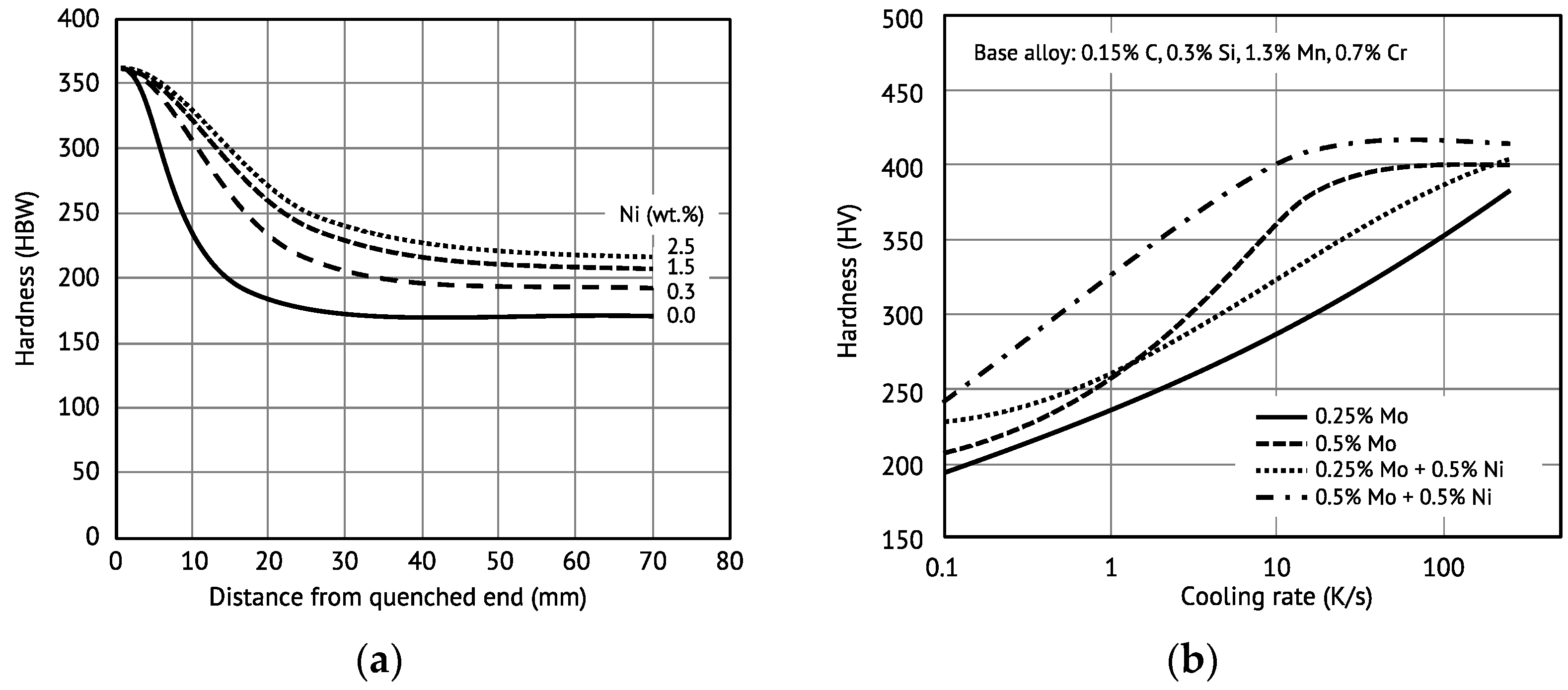
Figure 4a illustrates the hardenability as a function of the nickel content in structural steel grade S460 by comparing Jominy curves. It is evident that the hardenability increase is most prominent for smaller nickel additions. At higher nickel content the increasing effect on hardenability levels off. The hardness increase occurs along with a gradual shift from a ferritic–pearlitic towards a bainitic–martensitic microstructure.
Figure 4b demonstrates the synergy between Ni and Mo in the function of the cooling rate. The molybdenum-related hardenability is not very pronounced at low cooling rates, irrespective of the added amount. Nickel alloying, on the contrary, provides better hardenability at these low cooling rates. At higher cooling rates the hardenability effect by 0.5 wt.% Mo is saturating. Combined alloying of Ni and Mo to 0.5 wt.%, each, provides very good hardenability, one which is better than the sum of the individual alloy effects for cooling rates up to 10 K/s.
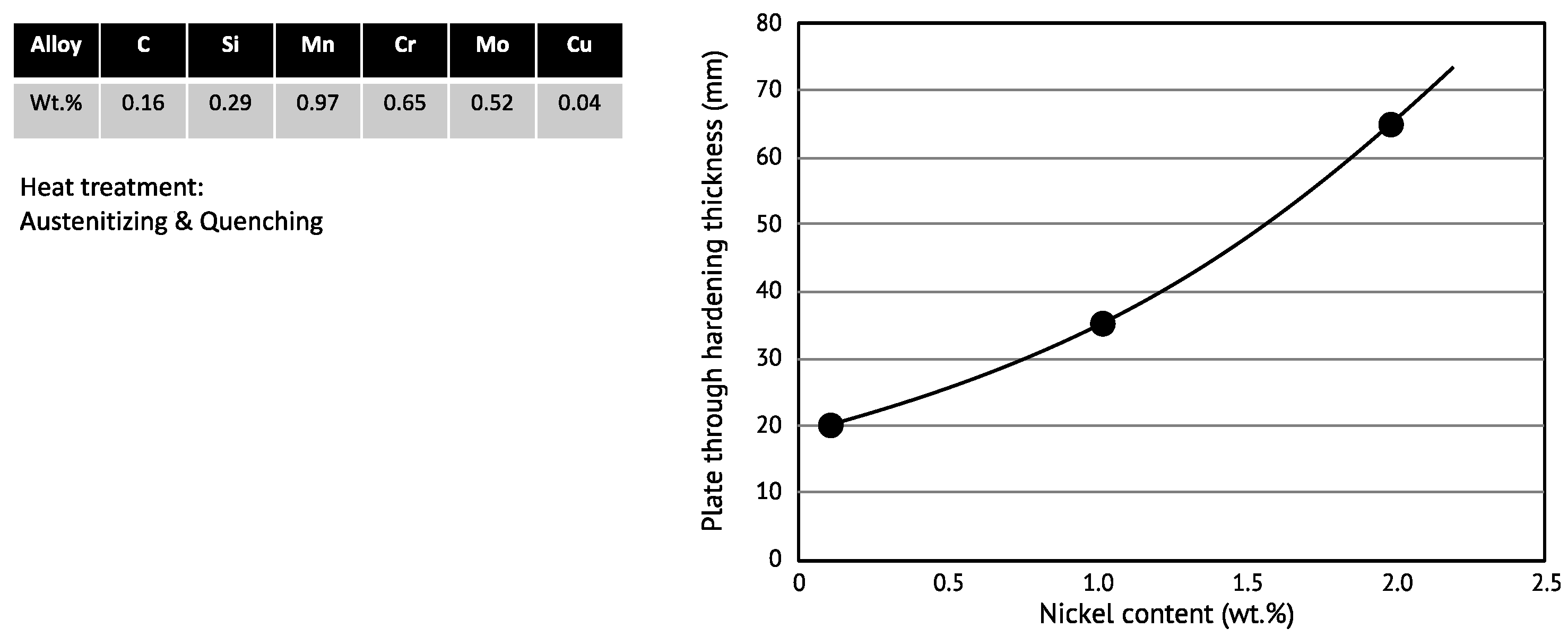
The nickel-induced lowering of the transformation temperature and the associated increase in the driving force for the bainitic transformation results in a refinement of the bainite package and block size, which noticeably supports the hardness-increasing effect of nickel [
24,
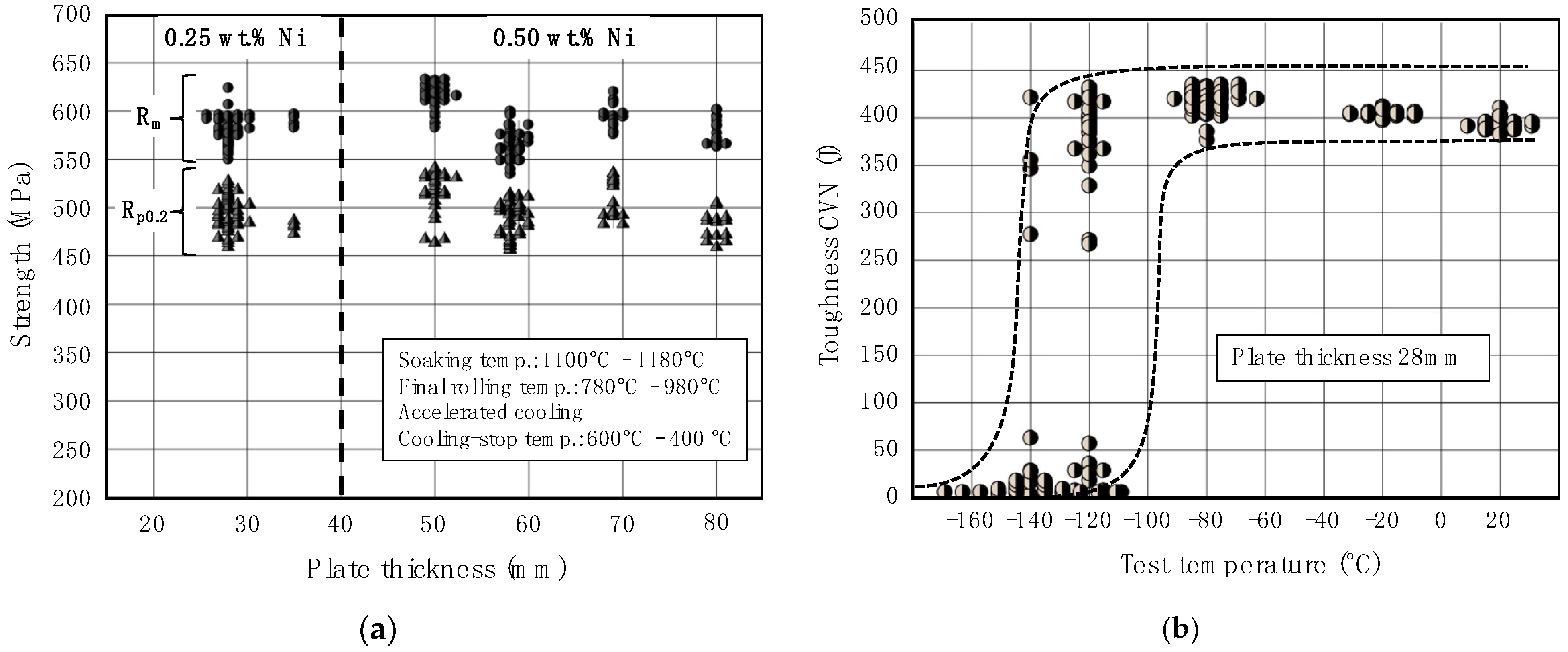
25]. Lowering the carbon content and increasing the nickel addition promotes this refinement. The resulting enhanced density of block boundaries and Bain variant pairs leads to a high hardness even at the low cooling rates encountered in the center section of heavy-gauged products. Alloying 2 wt.% Ni to a water-quenched high-strength steel allows the through-hardenable plate thickness to be more than tripled, as demonstrated by
Figure 5.
2.4. Solute Atom Effects of Nickel
The variation in the lattice parameters of austenite and ferrite, with the addition of an alloying element, strongly depends upon the relative difference in atomic radius between iron and the alloying element: the so-called misfit parameter. Nickel, like manganese and chromium, has an atomic size rather similar to that of iron. Accordingly, it has a small effect on the lattice parameter in bcc iron. Leslie [
26] and, more recently, Hagi [
27] have provided quantitative data for this effect. Host lattice distortion by nickel alloying is accordingly rather small. Nevertheless, solute nickel has a quite significant effect on the Young’s (
E) and shear (
G) moduli of bcc iron. Ledbetter and Reed [
28] derived relationships describing the influence of nickel content
CNi in wt.% as
which can have important consequences, for instance, regarding the fracture behavior of carbon steels. Accordingly, Morris et al. [
29] pointed out that in a Fe-12 wt.%Ni alloy the ideal cleavage and shear strengths are respectively more than 10% and 16% below that of pure Fe, and a ferritic alloy containing more than 32 wt.% Ni would become virtually immune to cleavage.
The interaction of alloying elements in substitutional solution with defects and interstitials is controlled by the lattice strain caused by the alloying atom. It is reasonable to assume that the solid solution strengthening effect should correlate with the misfit parameter. The normalized lattice distortion is proportional to the concentration of the substitutional element and has been reported to be in the range of 1.65−2.31 × 10
−4 per at.% for nickel which is very similar to that for manganese (1.80−2.30 × 10
−4 1/at.%) and larger than that for chromium (1.20−1.90 × 10
−4 per at.%) [
27]. In comparison, larger-sized substitutional atoms such as molybdenum or vanadium cause much bigger misfits, in the range of 5.21−8.36 × 10
−4 per at.% and 3.53−4.04 × 10
−4 per at.% [
27]. While chromium, vanadium, and molybdenum fit quite well to a linear correlation between misfit parameter and solid solution strengthening, nickel and manganese strengthen bcc iron more than their misfit parameter suggests [
30]. Under tensile test conditions at ambient temperature (23 °C) and low strain rate (10
−4 s
−1) around a 20 MPa yield strength increase per at.% Ni alloy addition can be achieved by solid solution strengthening [
30]. On the other hand, binary iron alloys containing Ni (and similarly Mn, Al and Si) exhibit solid solution softening below a temperature of 250 K [
30,
31,
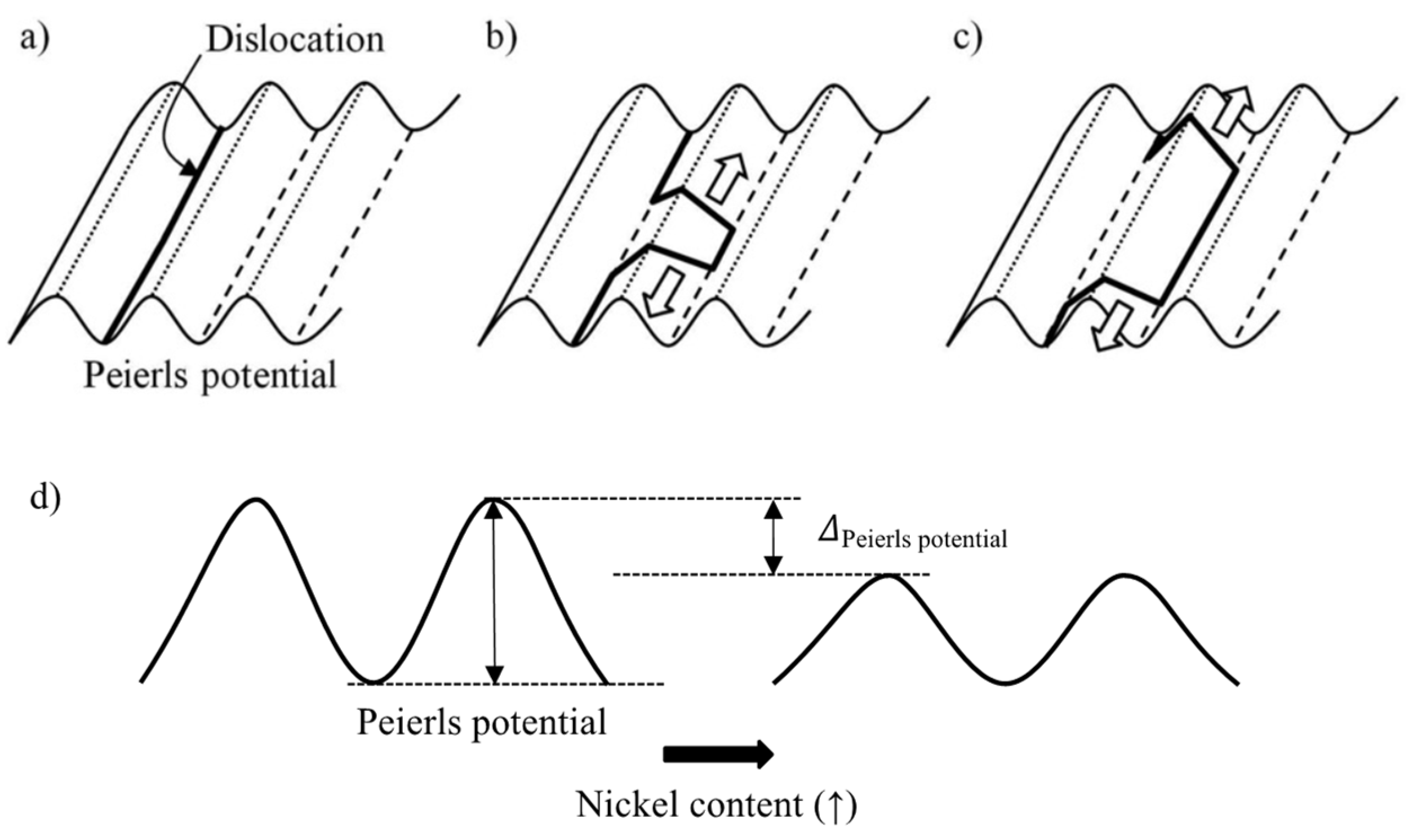
32]. Solid solution softening has been attributed to a decrease in the kink-pair nucleation energy with increasing solute content. Following the original suggestion by Weertman, a solute atom misfit center would interact with a dislocation, helping to pull it out of the Peierls energy valley [
33,
34]. This interpretation, however, does not assume a direct influence of nickel on the Peierls stress. The experimental results of Hildebrandt and Dickenscheid [
35] prove that the activation energy for slip in Fe–Ni alloys is reduced relative to pure iron. This difference increases with the nickel content over the investigated alloy range of up to 3 at.% and also increases the further that temperature decreases below ambient. The authors attributed this behavior to a disturbance in the iron matrix caused by the change of the lattice parameter and elastic modulus due to nickel alloying. Furthermore, it was argued that nickel fills the incomplete 3d electron shell of iron, thus diminishing the influence of covalent bonding so that more active slip systems are available at low temperature. Chen et al. [
36] have presented results on the plastic flow of binary Fe–Ni alloys, which are congruent with those reported in [
35]. Their analysis indeed suggests that the Peierls stress decreased from 920 MPa in pure iron to 640 MPa when adding 4 at.%. Ni. The temperature dependence of the strain rate sensitivity exposes a local minimum, which shifts towards lower temperatures with increasing nickel content.
Due to its relatively small misfit parameter, high solubility and slow diffusivity in iron, nickel has only a weak tendency for segregating to grain boundaries. This is contrary to solute atoms inducing a larger misfit such as molybdenum or niobium [
30,
37]. The low binding energy of nickel to the boundary results in a comparably small solute drag effect. Empirical work by Lee [
38] indicates that the contribution of nickel in enhancing the activation energy for austenite grain growth is considerably lower than that of molybdenum and also lower than that of chromium. Ab-initio calculations by Hoerner et al. [
39] demonstrate a good correlation between the binding energy of solutes to preferential substitutional sites and the activation energy for austenite growth. Accordingly, nickel has a small impact on obstructing the boundary mobility, which is a major factor regarding austenite recrystallization and grain growth. Research by Jin et al. [
40], using first-principle calculations, suggests that nickel also has a low binding energy to the bcc–fcc transformation interface. Hence, its solute drag effect on the phase transformation front is also small. Modelling of alloy effects on ferrite growth proceeding from the transformation of austenite by Zurob et al. [
41] confirmed a weak interaction of nickel with the interface along with the tendency for carbon to repel nickel from the interface.
High temperature plasticity in ferrite relies on the mobility of dislocations and recovery phenomena. Solute alloy atoms can retard the gliding motion of dislocations by dragging. The climbing motion of dislocations is controlled by vacancy flow towards the dislocation core. Yoshida et al. [
42] have argued that the dragging force of solutes on dislocation gliding is determined by the solute misfit parameter and its self-diffusion coefficient. Accordingly, nickel has only a small drag effect which is owed mostly to its limited diffusivity rather than to its small misfit.
The diffusion coefficient of nickel in a highly defective microstructure, however, can be considerably increased as compared to normal lattice diffusion [
43]. Enhanced nickel diffusion has been observed, for instance, after cold-working or neutron irradiation [
44]. Thereby the activation energy for diffusion of nickel in the highly defective steel microstructure is attributed mainly to the activation energy for vacancy migration. In that case, the already weak obstructive effect of solute nickel on dislocation glide or recovery should be further reduced. Enhanced nickel diffusivity is also promoting nickel partitioning during heat treatment in the temperature range of coexisting ferrite and austenite. This is the case when a defect-rich original microstructure such as martensite is tempered in the inter-critical temperature range resulting in a fraction of metastable retained austenite.
Another plasticity-influencing effect of nickel is related to a change in stacking fault energy (SFE). In fcc metals, such as austenite, stacking faults (SF) are interruptions in the perfect (ABCABC) sequential layering of the (111) crystallographic planes. These faults are formed by either dissociation of a perfect dislocation into two partial dislocations, or by emission of partial dislocations from grain boundaries. The stacking fault energy is required for generating this lattice irregularity. Pure nickel metal has a comparably high stacking fault energy (SFE ~128 mJ/m
2) so that the number of stacking faults is relatively low, explaining its good plasticity. When nickel is alloyed to austenitic steel it also increases the stacking fault energy of the iron matrix. The magnitude of the effect was found to be ~2.8 mJ/m
2 per wt.% nickel added [
45]. This value is larger than that for other alloying elements such as molybdenum (~2.0 mJ/m
2), chromium (~0.4 mJ/m
2) and manganese (~0.75 mJ/m
2) per wt.% addition [
45]. The level of stacking fault energy has an impact on the deformation characteristics of the material such as the work-hardening and softening behavior. Low SFE values, typically less than 45 mJ/m
2, lead to widely dissociated dislocations whose movements are therefore confined to the slip planes, whereas localized cross-slip is extremely difficult. Higher SFE results in a lower barrier to dislocation motion due to the ability of cross slipping without splitting up into partial dislocations. The reduction of Peierls stress, in combination with the increase in dislocation mobility assisted by higher SFE (
Figure 6) in nickel alloyed steels, is the metal-physical origin for improved toughness properties under impact loading (see
Section 2.6) as well as better ductility in cold-forming processes.
The work-hardening rate is controlled by ease of cross-slip governed by the SFE, which in austenitic stainless steel is influenced by alloying elements [
46]. Regarding carbon steels, the SFE and potential effects by nickel alloying are relevant to hot deformation in the austenite range and the behavior of potentially retained austenite phases in final condition. Strain hardening and softening processes take place alternately during hot rolling of the austenitic microstructure. Softening is caused either by recovery or recrystallization. The increase of the SFE by nickel alloying and the correspondingly improved dislocation mobility should promote recovery as softening mechanism during hot deformation. However, the overall recrystallization kinetics of the steel is not noticeably changed by nickel. Only the solute-drag effect caused by substitutional solutes delays the speed of the necessary grain boundary movement for a given recrystallization driving force. Retained austenite in carbon steel deforms by various secondary plasticity mechanisms, such as mechanical twinning (18 ≲ γ ≲ 45 mJ∙m
−2) and martensite transformation (<18 mJ∙m
−2) [
47]. In that respect, the amount of nickel partitioned to the retained austenite might influence the mechanical properties of this phase.
2.5. Nickel Interaction with Copper
Copper alloyed steels are sensitive to cracking during hot forming operations, a phenomenon also known by the term “hot shortness” [
48]. This phenomenon typically occurs at temperatures above 1000 °C due to copper enrichment at the steel surface below the iron oxide (FeO) layer [
49]. When the copper enrichment reaches a level exceeding its solubility limit in iron, copper-rich phases precipitate at the interface between oxide scale and metal. The solubility of copper in austenite in the relevant temperature range is in the order of 8 wt.% [
50]. The penetration of liquefied copper-rich phases along the austenite grain boundary cause liquid metal embrittlement (LME) and result in the disintegration of the steel under the simultaneous action of mechanical stress. Nickel alloying has two effects in this respect, alleviating or preventing this detrimental LME effect of copper. Firstly, nickel increases the solubility of copper in austenite [
51], thus retarding the precipitation of copper-rich phases. Secondly, nickel, which also enriches at the interface between the oxide scale and metal surface, is completely miscible with copper in their binary alloy system. The solidus temperature increases nearly linearly from 1083 °C for pure copper to 1453 °C for pure nickel. Accordingly, the melting temperature of a 50%Cu–50%Ni alloy is at around 1250 °C. This temperature generally represents an upper limit for steel soaking before hot deformation is performed, usually at temperatures below 1200 °C. Hence, the simultaneous addition of nickel and copper in equal amounts successfully prevents hot shortness. More recent research has suggested that the addition of nickel in the ratio Ni:Cu = 1:2 might be sufficient for suppressing the hot shortness problem when copper is at residual levels originating, for instance, from recycling scrap used in electric arc furnace operations [
52].
Regarding slab straightening after continuous casting, another hot ductility reducing effect of copper is related to the precipitation of fine copper sulfide or oxysulphide particles at austenite grain boundaries [
53]. The increased solubility of Cu in austenite due to Ni alloying reduces the driving force for Cu precipitation, thus restoring the hot ductility for both straightening and hot rolling. Moreover, Ni appears to have a beneficial influence on the hot ductility of HSLA steels and also in the absence of Cu [
53]. This effect has been related to the coarsening of micro-alloy carbonitride precipitates, which may be due to the enhancement of carbon activity by nickel alloying (see
Section 2.2).
A subclass of HSLA steels employs copper precipitation for the production of high strength in addition to that which can be achieved by the more commonly used micro-alloy precipitation. The low carbon content in these steels, in combination with fine
ε-Cu particles precipitated during a thermal ageing process, impart a favorable combination of strength and toughness to such steels [
54]. In peak-aged condition, the coherent copper precipitates with bcc lattice structure generally have an average diameter of between 1 and 5 nm. The magnitude of precipitation strengthening is controlled by the number density of these particles and can reach several hundred MPa. Nickel alloying to such copper-based age hardening steels is advisable due to the priorly mentioned hot shortness problems. In addition, synergies between the two elements regarding the formation of nano-precipitates have been revealed in Cu–Ni alloyed steels. Zhang and Enomoto [
55] have described the way in which the particle number density of a 1.5% Cu-alloyed steel almost doubled under the same treatment conditions when 3%Ni was co-alloyed. The higher particle count seems to be related to a significantly increased particle nucleation rate in the Cu–Ni steel. However, the particle size was only slightly larger under the same ageing conditions. The TTT curves describing the kinetics of Cu precipitation are clearly shifted towards shorter times by nickel alloying. Vaynman et al. [
56] exploited this Cu–Ni precipitation synergy for the design of a 965 MPa (140 ksi) steel by alloying 1.3%Cu and 2.7%Ni to a very low carbon base chemistry. The detailed analysis of the precipitates using atom probe tomography (APT) revealed the segregation of Ni, Al, and Mn to the precipitate/ferrite matrix interfaces of the Cu-rich precipitates after longer ageing time. A more recent work by Jiao et al. [
57] has revealed substantial precipitation strengthening in ferritic steel by using 2%Cu in combination with 0.75%Ni. While the copper-only alloyed steel achieved a precipitate strengthening effect of 132 MPa, the addition of nickel increased the magnitude of this effect to 437 MPa. It has been argued that the inclusion of Ni atoms in a Cu-rich nucleus decreases the strain energy for nucleation. Furthermore, segregation of Ni atoms to the particle/matrix interface also decreases the interfacial energy.
2.6. Nickel Effect on Toughness
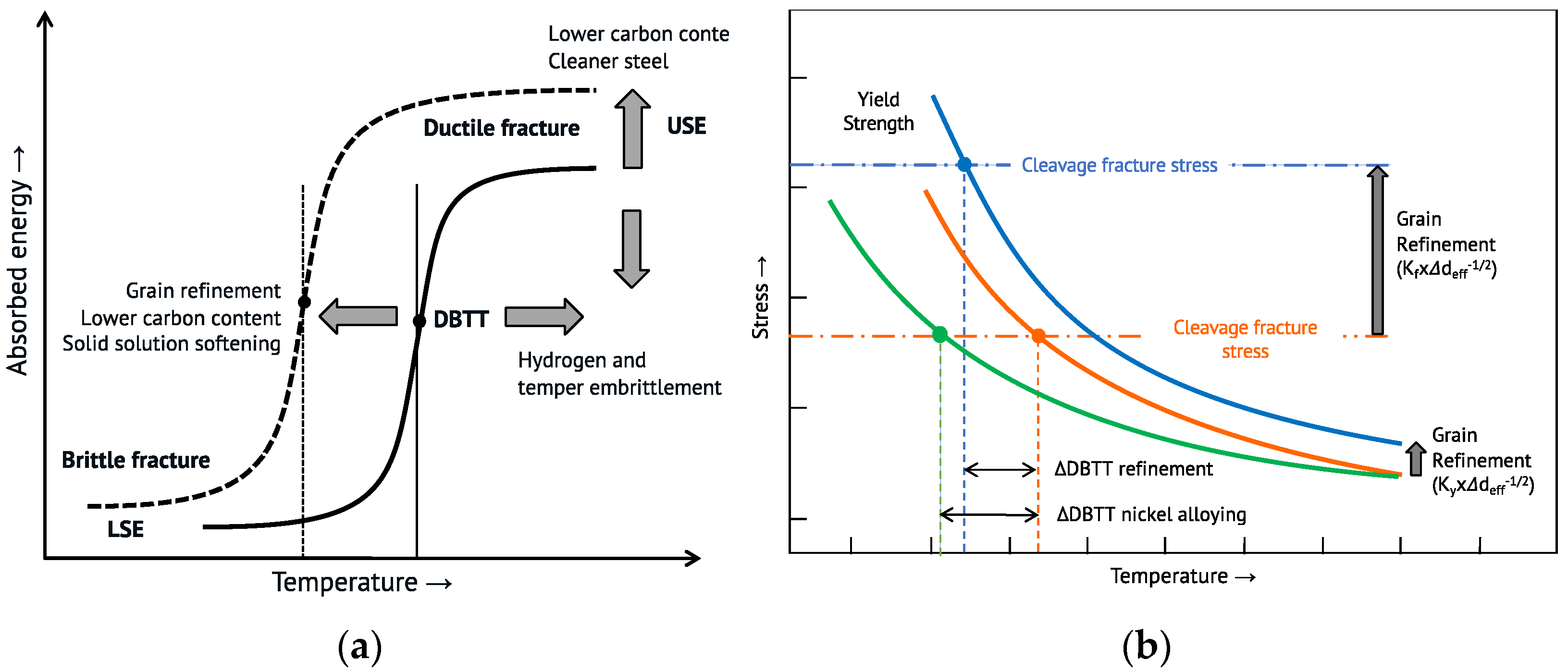
One of the most prominent effects of nickel in carbon steels is its improvement of toughness properties. A transitional behavior from ductile behavior with high upper-shelf energy (USE) to brittle failure with lower-shelf energy (LSE) is observed in steel with a bcc lattice structure when characterizing toughness by Charpy impact testing (
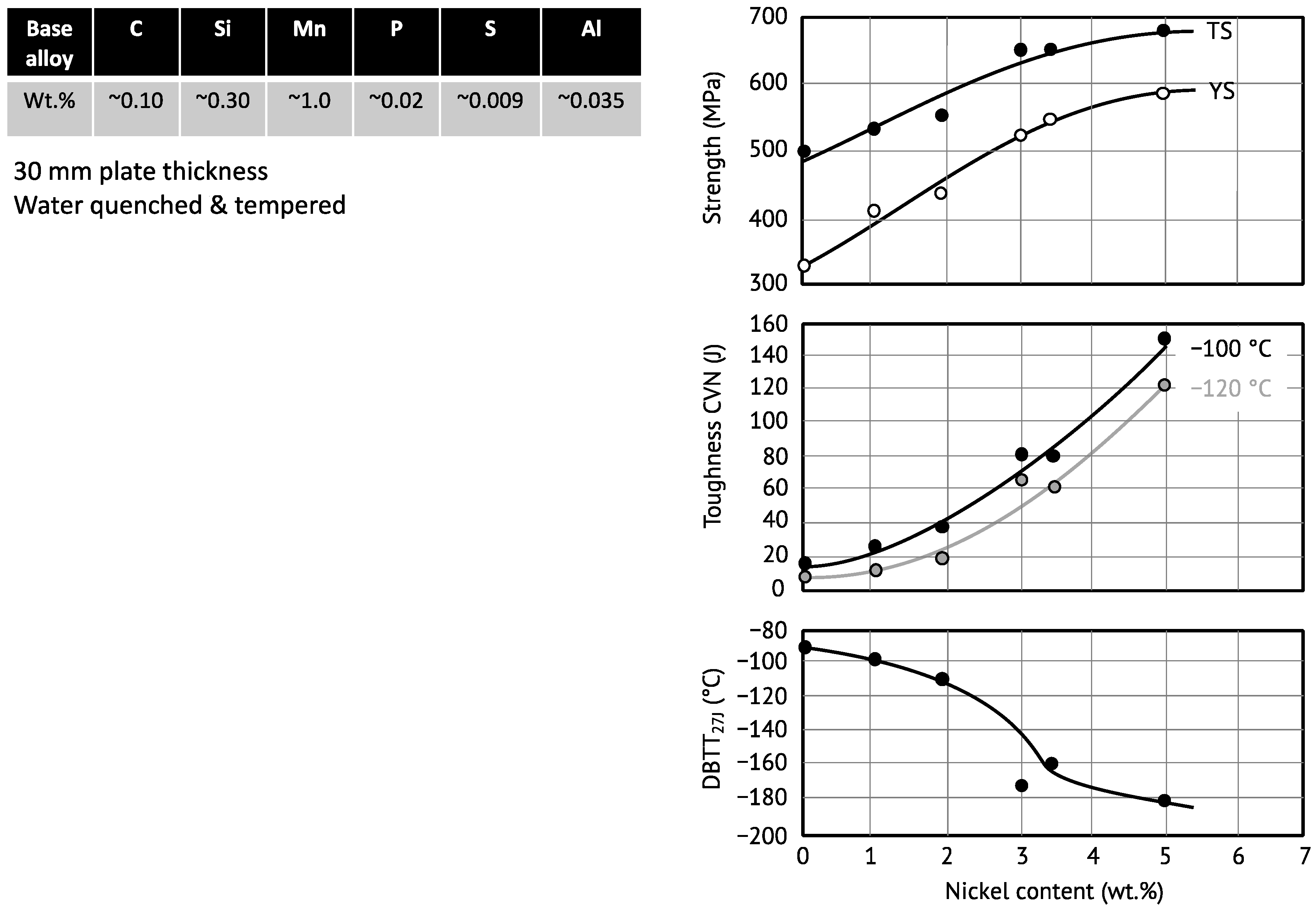
Figure 7a). The temperature at which the fracture surface has an equal share of ductile and brittle appearance is typically defined as the ductile-to-brittle transition temperature (DBTT). The DBTT of the selected bcc steel must be lower than the lowest encountered operating temperature in a technical application.
The evolution of steel development over the recent decades has focused on two major toughness-optimizing criteria in addition to generally lowering impurity levels and avoiding inclusions (
Figure 7a). The reduction of the carbon content results in an increase of USE and a significant decrease of DBTT [
58] while weldability is improved simultaneously. Grain refinement raises yield strength and also strongly decreases DBTT (
Figure 7b). Thus, grain refinement is the only strengthening mechanism that is also beneficial for toughness. The combination of low-carbon alloy design with maximized grain refinement achieved by thermomechanical rolling and accelerated cooling has led to high strength steels that behave as fully ductile at temperatures as low as −60 °C, i.e., DBTT is at around −80 °C [
59,
60]. However, this approach is beginning to reach its limits, wherein either applications require a very low DBTT, a low carbon content is not applicable, or product processing does not allow the application of substantial thermomechanical treatment for producing grain refinement.
Simplistically, the transition from ductile to intragranular (cleavage) fracture occurs when the effective yield strength at a certain low temperature exceeds the cleavage fracture stress (
Figure 7b). Both properties depend on grain size according to Hall–Petch type relationships as outlined in more detail by Morris [
61]. However, the Hall–Petch coefficient of the fracture stress (K
f), although dependent on the phase constitution of bcc steel (i.e., the size and distribution of carbide phases), is always larger than that of yield strength (K
y) [
62]. Yield strength shows a significant increase with decreasing temperature while the fracture stress experiences only a small change, mostly related to the temperature dependence of the elastic modulus. Due to the effects of solute nickel on the mobility of dislocations and therefore on the low temperature plasticity outlined in
Section 2.4, solute softening can substantially lower DBTT in nickel alloyed steels irrespective of grain refinement. As the Ni content is increased, the resolved shear stress on the most favorably oriented slip system approaches the cleavage stress along the <100> direction, and there is an increasing likelihood the crystal will shear before cleaving [
29]. Nickel additionally increases the effective surface energy for cleavage fracture, thus contributing to a higher cleavage fracture stress according to Gerberich et al. [
63]. The combination of both effects, namely reduced effective yield stress and increased cleavage fracture stress, results in a decreasing DBTT with nickel alloying from −32 °C in the unalloyed reference iron (polygonal ferritic) to −100 °C for 4 at.% Ni. Such nickel alloyed ferritic steels can compete with the best TMCP-rolled fine-grained low-carbon steels. As mentioned in
Section 2.4, other alloying elements such as Mn, Cu, Si, or Al also provoke a solid solution softening effect at low temperature that could be principally used for DBTT improvement. However, contrary to nickel these alloys increase DBTT after an initial improvement due to competing effects that promote transgranular or even intergranular fractures at higher alloy additions [
64,
65].
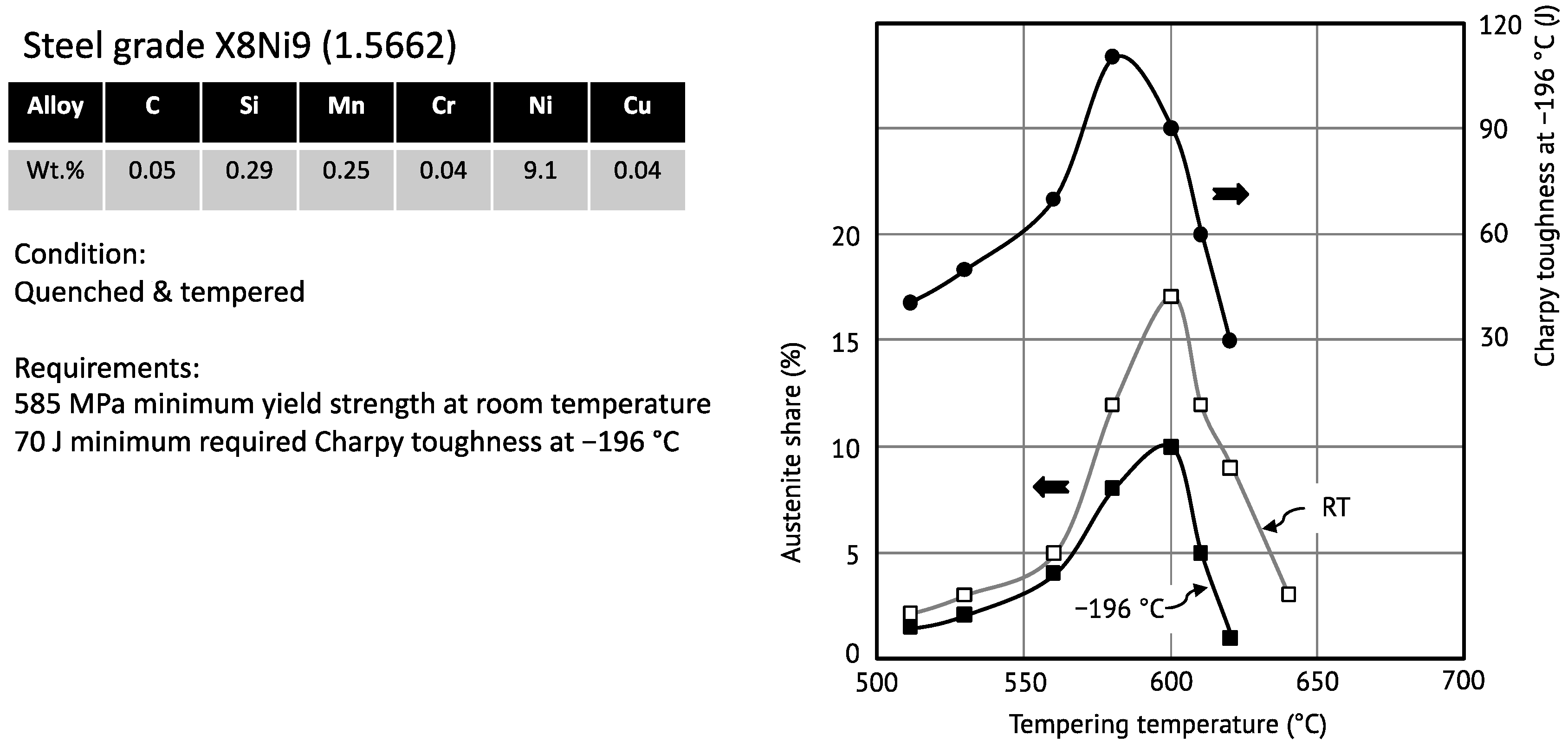
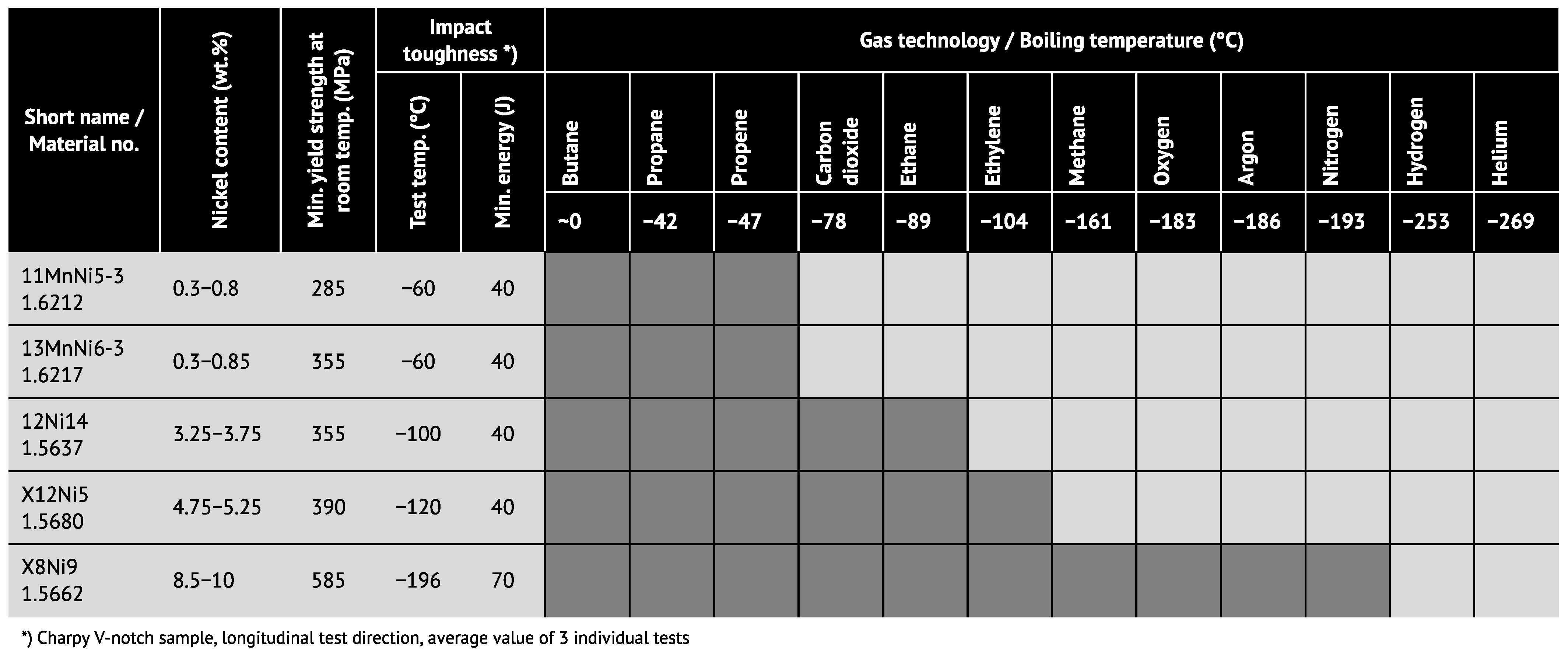
Extremely low DBTT is required for steels used in cryogenic applications. As early as the early 1960′s so-called “9Ni steel” had been established for cryogenic applications as a suitable alternative to austenitic steels. In 1964, Jesper and Achterlik [
4] reported on the mechanical properties of cryogenic steel grades with nickel contents between 1.5 and 13 wt.%, covering the operating temperature range from −50 to −200 °C. These steels are typically produced by quenching and tempering (Q&T) treatment [
4]. In addition to the mechanism by which solid solution softening accounts mainly for the improvement of low temperature toughness, the Q&T treatment results in a very fine grain structure and the formation of retained austenite islands. Nickel partitioning stabilizes a small fraction of retained austenite during tempering at temperatures in the two-phase region between the A
c1 and A
c3 temperatures (
Figure 1c). An optimized retained austenite content results in exceptionally high toughness at temperatures below −100 °C.
Figure 8 exemplarily demonstrates the influence of the retained austenite on low-temperature toughness for a steel containing approximately 9 wt.% Ni [
65].
The austenite phase fraction and the impact energy at −196 °C behave congruently in the function of the tempering temperature of the steel. It should be noted that the initial reversed austenite is metastable and partially transforms into martensite when cooling to cryogenic temperature. Morris et al. [
29] have pointed out that the toughness enhancing effect of retained austenite is not caused by “transformation toughening”. Accordingly, the crystallographic variant forming upon transformation under load is that which best relaxes the local stress. It decomposes the martensite packet by introducing features of different crystallographic orientation with the effect of inhibiting cleavage fracture. For an optimum exploitation of this mechanism, the precipitated austenite must be thermally stable and densely distributed through the microstructure. For that purpose, a relatively low tempering temperature close to the A
c1 line is preferrable.
Empirical data of the Charpy toughness measured by notched bar impact testing can be closely correlated with the fracture toughness obtained by fracture mechanics testing. Thereby, the temperature for achieving a 100 MPa∙m
1/2 fracture toughness is related to the Charpy 27 J transition temperature as per [
66,
67]:
Since nickel alloying reduces the T27 temperature, the fracture toughness is correspondingly improved at lower temperature.
2.7. Nickel Effect on Environmentally Assisted Cracking (EAC)
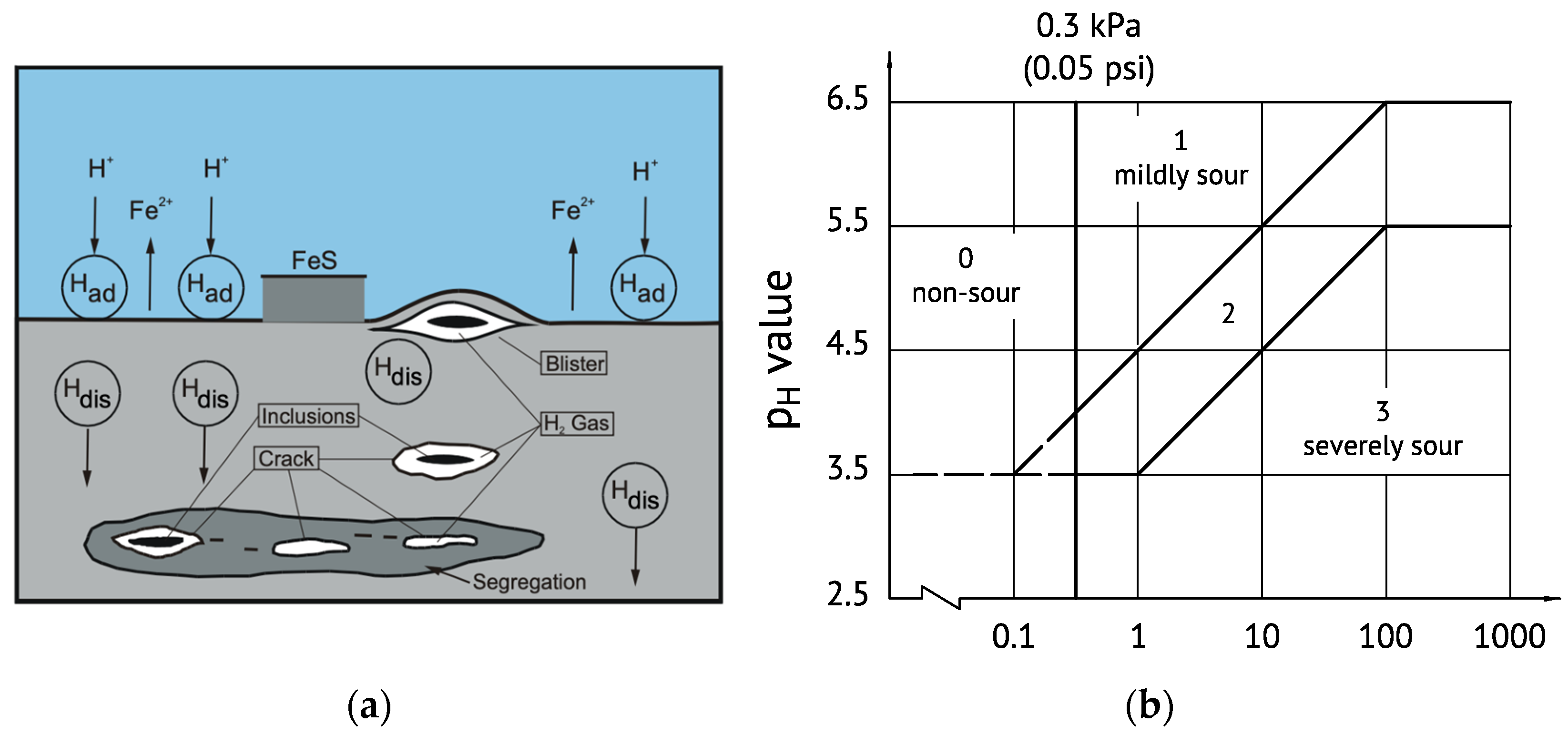
Hydrogen has the highest diffusivity of all interstitial elements in the bcc iron lattice and interacts with defects and different types of hydrogen traps. The local accumulation of hydrogen at interfaces and defects causes various types of hydrogen embrittlement (HE) as well as hydrogen-induced cracking (HIC) or stress corrosion cracking (SCC) depending on the hydrogen concentration [
68]. This problem is highly relevant to medium-strength HSLA steels continuously operating in contact with sour media and also typically to ultra-high strength steels even when occasionally undergoing hydrogen pick-up. Hydrogen is usually introduced into the iron lattice by adsorption of atomic hydrogen (H
ad) as the result of a chemical reaction at the steel surface, providing dissolved hydrogen (H
dis) in the bulk steel as schematically shown in
Figure 9a. ISO standard 15156-2 [
69] defines four severity regions regarding the risk for HIC and SCC depending on the pH value and on the H
2S partial pressure in the surrounding medium (
Figure 9b). Currently, most low-alloyed carbon steels are accepted for service under any H
2S condition if they contain less than 1 wt.% nickel (max. limit of ISO 15156) and the hardness in the area exposed to the corrosive medium is kept below 250HV (22HRC). A detailed analysis of nickel’s effect on SCC has been performed by Kappes et al. [
70], who concluded that limiting the nickel content to 1.0 wt.% constrains materials selection and imposes serious economic and operational penalties for both high pressure and high temperature as well as arctic oil and gas operations.
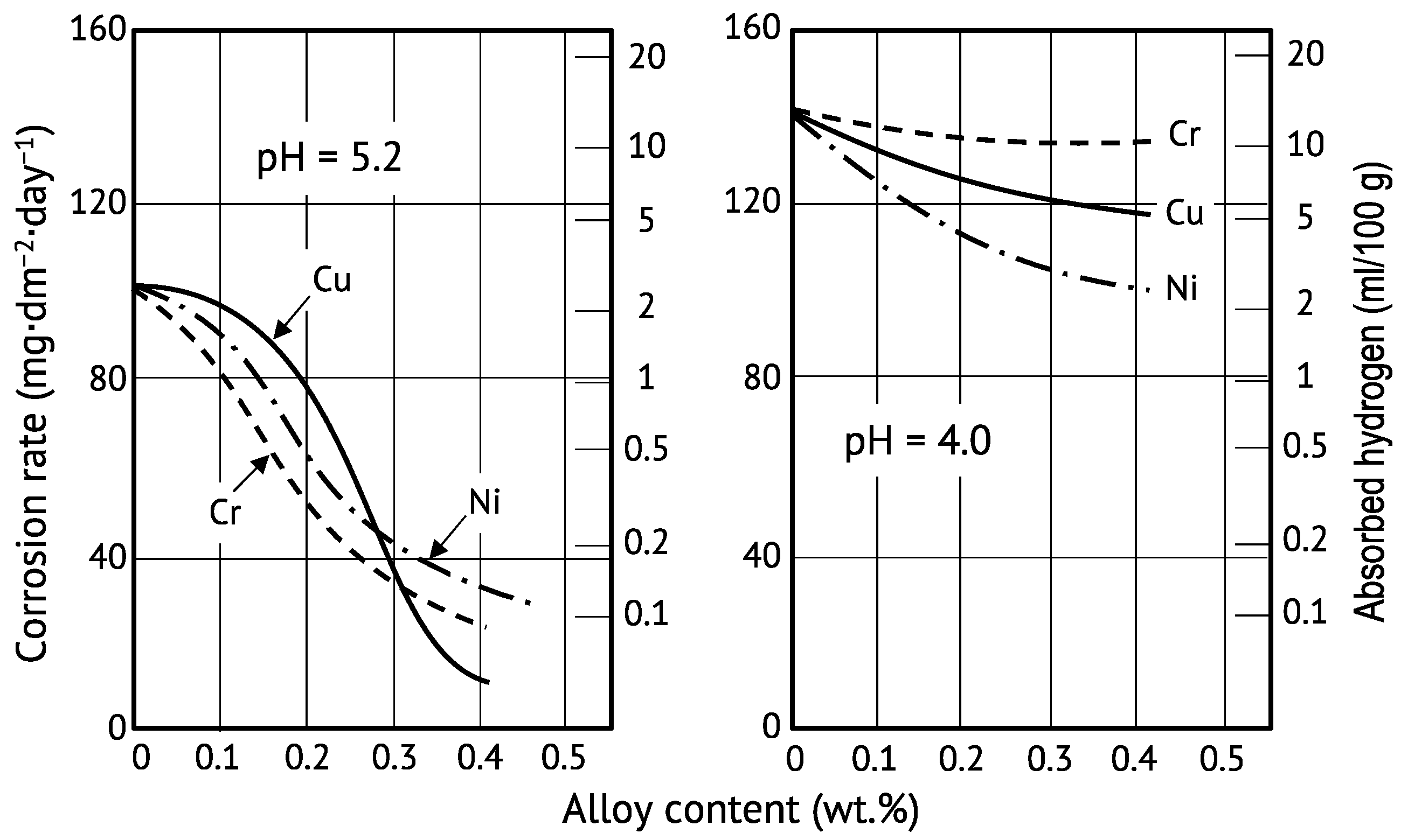
Metallurgical development in the 1980′s towards the production of sour-resistant line pipe steels with a yield strength in the range of 450–550 MPa, indicated that Cr, Cu and Ni alloying is effective in reducing the steel’s corrosion rate in aggressive media and accordingly lowers the hydrogen pick-up from the surface into the steel [
71]. While in a mildly sour environment (pH = 5.2) the corrosion inhibiting effect of these alloying elements is rather comparable, nickel alloying becomes clearly the most effective alloy in more aggressive environments at the lower pH value of 4.0 (
Figure 10).
From a more extensive review on nickel effects influencing the environmental assisted cracking (EAC) behavior of carbon steels by Jarvis and Bulloch [
68] it can be taken that improvements are related to (1) reduced overall corrosion rates and (2) decreased lattice diffusion of hydrogen. Since nickel promotes the formation of a protective layer by local enrichment at the steel surface, the effects of anodic dissolution will be reduced as the nickel content increases. The anodic dissolution of iron results in a corrosive weight loss. The corrosion rates shown in
Figure 10 suggest that this inhibiting effect becomes saturating above an alloy content of 0.4 wt.% Ni [
71]. Experiments on a medium carbon ultra-high strength steel (1500 MPa) immersed for 100 h in a pH 3.5 Walpole solution indicated the same trend [
72]. The corrosion rate clearly decreased for Ni addition of up to 0.5 wt.% while raising the Ni content to 1.0 wt.% showed only marginal further improvement. The open-circuit potential value obtained from polarization measurements, however, increased consistently with the nickel content. This occurred with a decreasing corrosion pit depth with increasing Ni content, reducing stress concentration. Nowadays, developments for automotive steels have been targeting a strength level of 2000 MPa. Such steels are very sensitive to hydrogen embrittlement and alloying strategies are therefore being developed to cope with that problem [
73]. In this regard, the effect of nickel alloying to medium-carbon steel (C content: 0.4–0.5 wt.%) was also investigated for additions in the range of 0.1 to 1.2 wt.% [
74]. Auger electron spectroscopy confirmed the presence of an approximately 4-nm thin nickel-enriched layer at the metal surface below the iron oxide scale. Immersion of these steels in a neutral aqueous environment of 3.5% NaCl indicated that the weight loss by corrosion linearly decreased with increasing nickel content up to 1.2 wt.% in this moderately aggressive medium. However, the reduced corrosive weight loss and the lower total uptake of hydrogen into the steel did not necessarily materialize in a better resistance against hydrogen embrittlement.
The observed incongruency of hydrogen embrittlement behavior in the function of nickel alloy addition relates to adverse microstructural effects competing with the beneficial functionality of nickel enrichment at the metal surface. Such microstructural features are the result of the alloy composition and heat treatment. It has been shown that by nickel’s effect of lowering the A
c1 temperature, dissolution of cementite might not be completed during the re-austenitizing phase [
75]. Initially formed Ni-rich austenite films obstruct the out-diffusion of carbon from dissolving cementite so that incompletely dissolved particles can be retained in the final product. Cementite particles in a corrosive environment act as a localized anode, especially when they are concentrated in the near-surface (Ni-enriched) layer [
75]. As outlined above, nickel alloying in combination with suitable heat treatment can also promote the formation of retained austenite. Hydrogen has a high solubility in austenite, while its diffusivity is low. Hence retained austenite islands in a ferritic microstructure act as an irreversible hydrogen trap, which in first place might be considered beneficial. However, when metastable retained austenite transforms into martensite triggered by plastic deformation, for instance at the tip of a proceeding crack, trapped hydrogen becomes highly diffusible in an area that simultaneously experiences high local dilatation stresses [
70]. Under such circumstances cracking might even be accelerated. Accordingly, retained austenite cannot be considered beneficial to improve SCC resistance [
76].
The interstitial lattice sites around substitutional solute atoms act as a reversible hydrogen trapping site. With increasing solute content, the hydrogen permeability and diffusivity should hence decrease. The interaction energy between hydrogen and the solute atom is expectedly related to the misfit parameter. Hagi [
27] has described the effect of several substitutional alloying elements on the diffusion coefficient of hydrogen in pure
α-iron. The chosen approach excluded any implications related to carbon containing phases and also avoided other potential trapping effects. Nickel alloying in the range of up to 5 at.% significantly reduced the hydrogen diffusivity from approximately 10
−8 m
2/s (Ni-free) to 5 × 10
−9 m
2/s (5 at.% Ni) at ambient temperature. Thereby the diffusivity reducing effect of nickel was larger than that of chromium, with a similar misfit parameter. It also had a similar misfit parameter as aluminum, inducing a much higher lattice misfit. The interpretation of this apparent inconsistency is that hydrogen diffusivity is not only influenced by elastic interaction (misfit) but also by chemical (electronic) interaction between the alloy atom and hydrogen. Experimental results from Husby et al. [
14] on ferritic-pearlitic steels (carbon content: 0.17 wt.%) with different nickel contents in the range of 0 to 3 wt.% showed the same trend regarding the effective hydrogen diffusion coefficient. These investigated steels had nearly the same grain size, but the pearlite fraction increased with the nickel content, likely additionally influencing the hydrogen diffusivity.
The relevance of grain size on the susceptibility of SA517 Grade F steel to hydrogen environment embrittlement in a 45 MPa gaseous hydrogen atmosphere has been demonstrated by Takasawa et al. [
77] using two Ni alloy levels (1 and 2 wt.%). The notch fracture stress under pressurized hydrogen conditions increased with the ASTM grain size number (i.e., finer grain size) while the influence of the nickel content appeared to be marginal. The amount of diffusible hydrogen picked up by the steel during tensile testing was higher the larger the grain size. Simultaneously, the hydrogen concentration per unit grain boundary area increases with larger grain sizes, which is the main reason for reduced fracture stress. At first sight, the nickel content has thusly no influence on these results. However, the decrease in A
c3 temperature with increasing nickel content (see
Figure 1b) allows for re-austenitizing of the steel at lower temperatures. This results in a limitation of austenite grain growth. In that sense, nickel alloying can indirectly improve hydrogen embrittlement resistance.
2.8. Influence of Nickel on Fatigue Behavior
Most constructions are subjected to cyclic loading at stress levels below yield strength. Under these conditions, the microstructure experiences fatigue reducing the bearable strength level. Failure of components subjected to cyclic loading under different loading scenarios (pulsating, alternating, etc.) consists of two stages: crack initiation and crack growth until the fracture toughness is reached. This particularly applies to the low-cycle fatigue domain. Depending on the applied stress, the Wöhler curve indicates the number of load cycles that can be endured until the occurrence of fatigue fracture. The Wöhler curve is divided into the domains of low-cycle fatigue and fatigue endurance. Nickel has a positive effect on the improvement of fatigue strength of structural steels by enhancing the fracture toughness, especially at low temperatures, as shown in
Section 2.6 and according to Equation (3). Fracture toughness determines the crack growth rate
da/
dN as a function of the stress intensity factor ∆
K ahead of the crack according to the well-established Paris–Erdogan crack propagation law:
The constants
C and
m can be determined from a log–log plot. Tobler and Cheng [
78] defined two regions:
- (1)
In a low-toughness region m increases as K1c decreases; temperature, Young’s modulus and yield strength influence the fatigue performance as well.
- (2)
In a high-toughness region m remains constant and independent of K1c.
Nickel alloyed ferritic steels were shown to have a constant m-value in the range of 2 to 4 at ambient temperature, irrespective of the nickel content [
78]. When testing fatigue crack growth at 76 K, however, the m-value exhibited a strong linear correlation with the nickel content between 0 and 5 wt.% whereas steels with nickel additions above 5 wt.% behaved according to the high-toughness region. Park et al. [
79] recently confirmed this behavior for various Q&T steels containing between 3.5 and 9 wt.% Ni. They point out that, especially at low service temperatures, the crack-growth rate for a given stress intensity level is lowered by the addition of Ni. However, they remark that the
K1c parameter does not accurately reflect the plastic deformation and related strain hardening occurring in the neighborhood of the crack tip. Therefore, the transition temperature between toughness regions (1) and (2) may be predicted inaccurately by using K
1c. Alternatively, a correlation between CTOD and m-value was suggested for determining the transition temperature form ductile to brittle fatigue fracture.
2.9. Influence of Nickel on Welding Behavior
Nickel is the only alloying element that improves strength and toughness properties simultaneously without having a significantly negative effect on weldability. This is reflected in the various empirical definitions of the carbon equivalent (CE) used for judging the weldability of steels, of which the most important are:
The multiplying factor of nickel is smaller than that of other common alloying elements such as Cr, Mo, Si, V, and Mn in all three CE definitions. The nickel alloy addition to weldable structural steels is limited by commonly applied standards for structural steels (EN-10025–3/-4: 0.8 wt.%, EN-10225: 0.7 wt.%, Norsok: 1.0 wt.%), i.e., its maximum contribution to these CE definitions (Equations (5)–(7)) is 0.067, 0.025 and 0.017, respectively.
The toughness-increasing effect related to nickel alloying discussed in
Section 2.6 is also reflected in the properties of welded joints. This holds for the coarse-grained heat affected zone (CGHAZ) [
80,
81] as well as for the weld metal [
82,
83,
84]. Nickel retards the nucleation and growth kinetics of grain boundary ferrite, refines the microstructure, and increases the share of acicular ferrite at the expense of grain boundary ferrite (
Figure 2b). Huang et al. [
81] have demonstrated this effect in low-carbon steels containing up to 0.5 wt.% Ni. They also noticed a reduced fraction of the detrimental MA phase. Nickel alloying markedly increased the CGHAZ toughness at −20 °C for low and high heat-input welding conditions, with ductile fracture appearance in both cases. You et al. [
80] investigated the influence of higher nickel additions (0.8 and 3.7 wt.%) on the CGHAZ microstructure. For the selected weld cycle representing a heat input of 6 kJ/cm, the applied NbTi micro-alloy concept could not prevent substantial austenite coarsening at a peak metal temperature of 1300 °C. However, CGHAZ toughness at −20 °C was maintained at a high level. It appeared that the benefit of nickel alloying is not related to austenite refinement but rather to an optimization of microstructural features developing within the rather coarse prior austenite grains upon transformation. A detailed microstructural analysis led to the conclusion that with increasing nickel content the microstructure changes from a mix of acicular ferrite plus lower bainite to pure lower bainite with a reduced fraction of carbon-rich islands (retained austenite and MA). In that sense, a higher nickel content, lowering the transformation temperature, makes the transformation more complete and uniform, thus suppressing carbon partitioning as a mechanism for the formation of unwanted hard phases. Furthermore, a higher nickel content changes the configuration of the Bain groups in the crystallographic packet within the prior austenite grain while the density of high-angle boundaries remains almost the same [
80].
Property demands regarding weld metal also focus on a combination of high strength and good toughness. The weld metal representing a solidification microstructure has limited possibilities for property optimization except by alloying. Often the alloy content needs to be substantially raised for matching weld metal strength to the base metal. The initially columnar austenitic microstructure of the weld metal decomposes into grain boundary ferrite (GBF), ferrite side plates (FSP), acicular ferrite (AF) and, in certain circumstances, MA constituents. AF microstructure can be considered favorable for strength and toughness while GBF and FSP are detrimental. Both Mn and Ni affect the microstructure in a similar way by depressing the transformation temperature, thus, preventing GBF and FSP formation in favor of AF. Accordingly, welding consumables for demanding tasks often employ increased Mn and Ni contents. Zhang and Farrar [
84] investigated suitable combinations of both alloying elements. It was found that Mn additions in the range of 0.7 to 1.5 wt.% and nickel contents between 1.0 and 3.5 wt.% deliver the best weld metal toughness. Regarding low temperature toughness, the functionality of nickel is superior to that of manganese for reasons outlined in
Section 2.6. The addition of nickel to the weld metal effectively promotes the formation of acicular ferrite while significantly reducing the amount of grain boundary ferrite, both at the higher and lower manganese levels [
84]. A nickel content over 5 wt.% produces larger amounts of martensite and coalesced bainite. Martensite can form also in interdendritic regions as a consequence of significant nickel and manganese segregation in weld metals containing 7–9 wt.% Ni and 2 wt.% Mn [
85]. A systematic investigation of Ni–Mn alloy combinations in ultra-low carbon (<0.02 wt.%) weld metals by Kang et al. [
6] arrived at similar conclusions. It is favorable to decorate prior columnar austenite grain boundaries with grain boundary ferrite to prevent the risk of intergranular fracture for the reasons explained in
Section 2.1 (see also
Figure 1c). In that sense manganese should range between 0.5 and 1.0 wt.% while the nickel content is recommended to be in the range of 4 to 5 wt.%. Alloy combinations within those ranges have achieved high weld metal toughness even at temperatures as low as −80 °C.


