Article

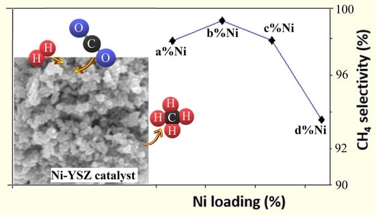
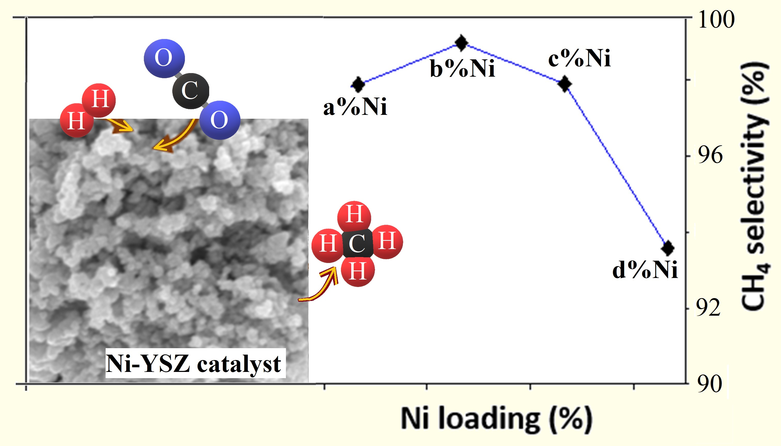
Investigating the Effect of Ni Loading on the Performance of Yttria-Stabilised Zirconia Supported Ni Catalyst during CO2 Methanation

by
Osaze Omoregbe
1,*,
Artur J. Majewski
1,
Robert Steinberger-Wilckens
1 and
Ahmad El-kharouf
2
1
Centre for Fuel Cell and Hydrogen Research, School of Chemical Engineering, University of Birmingham, Edgbaston, Birmingham B15 2TT, UK
2
Ove Arup & Partners Ltd., 3 St Paul’s Place, Norfolk Street, Sheffield S1 2JE, UK
*
Author to whom correspondence should be addressed.
Methane 2023, 2(1), 86-102; https://doi.org/10.3390/methane2010007
Submission received: 18 December 2022 / Revised: 21 January 2023 / Accepted: 6 February 2023 / Published: 8 February 2023
(This article belongs to the Special Issue Methane Conversion Technology)

Abstract

:
CO2 methanation was studied on Ni-based yttria-stabilised zirconia (Ni/YSZ) catalysts. The catalysts were prepared by the wet impregnation method, where the amount of Ni content was varied from 5% to 75%. Thereafter, the prepared catalysts were analysed by BET, XRD, SEM and H2-TPR. BET results showed an initial increase in the surface area with an increase in Ni loading, then a decrease after 30% Ni loading. The XRD results revealed that the Ni crystallite size increased as the Ni loading increased, while the H2-TPR showed a shift in reduction peak temperature to a higher temperature, indicating that the reducibility of the catalysts decreased as the Ni loading increased. The activity of the synthesised catalysts for CO2 methanation was studied by passing a mixture of H2, CO2 and N2 with a total flow of 135 mL min−1 and GHSV of 40,500 mL h−1 g−1 through a continuous flow quartz tube fixed-bed reactor (I.D. = 5.5 mm, wall thickness = 2 mm) containing 200 mg of the catalyst at a temperature range of 473 to 703 K under atmospheric pressure and a H2:CO2 ratio of 4. The tested Ni/YSZ catalysts showed an improvement in activity as the reaction temperature increased from 473 K to around 613 to 653 K, depending on the Ni loading. Beyond the optimum temperature, the catalyst’s activity started to decline, irrespective of the Ni loading. In particular, the 40% Ni/YSZ catalyst displayed the best performance, followed by the 30% Ni/YSZ catalyst. The improved activity at high Ni loading (40% Ni) was attributed to the increase in hydrogen coverage and improved site for both H2 and CO2 adsorption and activation.

Graphical Abstract

1. Introduction

The global energy demand continues to increase as a response to the growing world population and advancement in technology. Currently, fossil fuels account for the largest percentage of total energy generation. In 2020, fossil fuel sources provided over 80% of the global energy demand [1]. However, there are growing concerns due to the associated greenhouse emissions, which are largely responsible for the climate change crisis. The worldwide average amount of CO2 in the atmosphere reportedly hit a new record high of 413.2 ppm in 2020 [2]. This new level of CO2 has further placed pressure on nations to act fast in reducing greenhouse gas emissions. This was also the main topic of discussion in the COP26 and COP27, the United Nations Climate Change Summits held between 31 October to 12 November 2021 and 6 to 18 November 2022, respectively. Several solutions are being proposed, including the planting of trees and the replacement of fossil fuels with renewable and clean sources. However, the total energy produced from renewable sources is not yet able to meet the current world energy demand. Other problems associated with most renewable sources include energy storage challenges and volatility (weather and season dependency). Although great efforts have been channelled toward scaling up renewable energy production and energy storage capacity, the use of fossil fuels cannot be phased out in the short term. The international energy outlook data from the U.S. Energy Information Administration [1] showed that fossil fuels and their infrastructure will still be relevant and highly consumed in the next few decades.
Therefore, it is important to find ways of minimising CO2 emissions during the use of fossil fuels whilst the transition to renewable sources continues. One way of achieving this is to capture the CO2 emitted during the combustion process and convert it to useful products. This is a feasible process because CO2 is an essential feedstock for the production of C1-based fuels and their derivatives via various processes [3]. In recent times, the hydrogenation of CO2 into synthetic natural gas (SNG) has become a very attractive means of storing the excess energy generated from renewable sources [4,5]. Generally, energy from a renewable source is used to power electrolysers for hydrogen production, which is then utilised in CO2 hydrogenation through the Sabatier reaction to form synthetic methane (Equation (1)). The advantage of SNG over hydrogen is that it is fully compatible with the existing natural gas infrastructure. This power-to-gas strategy helps to minimise CO2 emissions while solving the storage challenge of renewable energy. CO2 captured from fossil fuel processes will in this way be re-utilised, thus reducing fossil CO2 emissions, but not preventing them. If the CO2 is obtained from biomass sources, no fossil CO2 will be released at all. Besides the climate mitigation point of view, it is also believed that CO2 methanation will be economically competitive if carbon capture and the electrolytic process for the required H2 are further improved and reduced in cost. As electricity from renewable energy sources has become the cheapest type of electricity in many parts of the world, and with the current developments in natural gas market, favourable economic conditions are clearly visible [6].
CO 2 + 4 H 2 CH 4 + 2 H 2 O     Δ H 298 K = 164   kJ   mol 1
Despite the promising potential of CO2 hydrogenation for renewable energy storage and CO2 utilisation, technological challenges remain, including heat management and catalyst deactivation. CO2 hydrogenation is thermodynamically favoured at low temperatures [7,8] but the temperature in the reactor is likely to increase above the starting temperature due to the strong exothermal character of the reaction. Consequently, reactor overheating can lead to hot spot formation which again causes catalyst deactivation through agglomeration and carbon deposition [9,10]. Interestingly, the heat released in the exothermic CO2 hydrogenation reaction can provide the energy required for the adsorption of CO2 on a dispersed adsorbent to spill over to the catalyst active sites where it is further converted [11]. Therefore, heat management is essential in the CO2 hydrogenation system for process optimisation.
It is also important to develop thermally stable catalysts with high activity and exceptional resistance to carbon deposition and sintering at the CO2 hydrogenation reaction conditions. In this regard, extensive research has been conducted on the application of various kinds of catalysts for the CO2 hydrogenation reaction [12,13,14]. Group VIII metals such as Pt, Pd, Ru, Rh, and Ni are among the most widely studied metal catalysts for CO2 hydrogenation owing to their high activity toward CO2 conversion [15,16,17,18,19]. Although the noble metal catalysts (Pt, Pd, Ru, Rh) have superior catalytic activity and stability compared to Ni, their application on a large scale is not feasible due to their high cost [20]. Hence, for CO2 hydrogenation, Ni-based catalysts are considered suitable alternatives to noble metal catalysts since they are considerably active, inexpensive and readily available [14]. Nevertheless, Ni-based catalysts are easily deactivated due to their poor resistance to carbon formation and to sintering during CO2 hydrogenation reactions [14]. Therefore, Ni catalysts are modified by the synthesis method [21,22], by application on supports with a good surface for the dispersion of the active metal [23], or by the incorporation of a promoter into the catalyst framework to enhance the dispersion of the active metal and improve CO2 adsorption, whilst minimising sintering [24].
Supports such as alumina (Al2O3), ceria (CeO2), silica (SiO2), titania (TiO2), and zirconia (ZrO2) have been extensively employed in the modification of Ni-based catalysts for CO2 hydrogenation reactions due to their ability to enhance the activity of Ni [25,26,27]. Specifically, ZrO2 has shown to be exceptional catalyst support for CO2 hydrogenation owing to its high thermal and chemical stability, high mechanical strength, and strong resistance to carbon deposition. These superior properties of ZrO2 can be attributed to its physicochemical properties which include the presence of defect sites (e.g., oxygen vacancies), Lewis acid sites (Zr3+, Zr4+), adsorbed O2− and OH groups (basic sites), and Zr4+-O2− acid-base pairs [28,29]. These properties also make the tuning and doping of ZrO2 more feasible for various catalytic processes. Moreover, the Lewis basic oxygen vacancies on ZrO2 are crucial for the adsorption and activation of CO2 [30] which is one of the major steps in the mechanism of CH4 formation during CO2 hydrogenation.
Generally, pure zirconia exists in three different crystal configurations, at atmospheric pressure and different temperatures: monoclinic (m-ZrO2), tetragonal (t-ZrO2) and cubic (c-ZrO2) [31,32,33,34,35]. Notwithstanding the great properties displayed by ZrO2, its redox activity is low due to the difficulty of its surfaces in discharging lattice oxygen atoms to form vacancies [36]. This challenge is overcome by doping the ZrO2 with metals with a lower valency than Zr (less than +4) such as Ni, La, Co, Ca, and Ti. The introduction of these dopants helps lower the energy required for the formation of oxygen vacancies through the substitution of some of the Zr4+ ions and the cleavage of the local symmetry of the lattice structure [36]. The introduction of lower valence dopants results in the alteration of the electronic arrangement of ZrO2, which affects the catalytic properties. It is worth noting that two unpaired electrons are left behind when oxygen vacancies are formed. These unpaired electrons can influence the catalytic cycle by enhancing the catalyst’s surface activity [36].
At low temperatures, the alteration in the crystal structure of ZrO2 can cause instability which limits its use in the industry [37,38]. This is why the cubic and tetragonal forms are generally stabilised at room temperature by doping with various metal oxides such as CeO2, MgO, CaO and Y2O3 [38]. Consequently, Y2O3 is mostly employed in stabilising ZrO2 owing to the improved stability effect it provides [32]. Another reason for the high preference for stabilising ZrO2 by Y2O3 is its influence in creating an oxygen vacancy in the anionic sub-lattice when two Zr4+ ions are replaced by two Y3+ ions, and this assists in the migration of oxygen ions through the yttria-stabilised zirconia (YSZ) material [39,40].
The use of ZrO2 as a support for CO2 methanation catalysts has been reported by many researchers. Gac et al. [41] studied the effect of Ni loading on Al2O3, ZrO2 and CeO2 supports. The authors reported that the increase in Ni loading from 10% to 40% on the ZrO2 resulted in a gradual decrease in the Ni crystallite size. The CeO2-supported catalysts showed the best performance followed by the ZrO2-supported catalysts in terms of CO2 conversion at 553 K. An increase in Ni loading was favoured for the CeO2 support, the performance of the ZrO2-supported catalyst was found to decrease after 20% Ni loading. In another study by Traitangwong et al. [42], Ni loading varied from 15% to 45% over Ni-modified ceria-zirconia support (e.g., Ni0.05Ce0.20Zr0.75O2) and the catalysts were tested for CO2 methanation. The catalyst with 45% Ni loading exhibited the best performance. The authors stated that increasing the Ni loading favoured the number of H2 molecules that were activated, which translated into higher catalytic performance.
Kosaka et al. [43] investigated the influence of Ni content on the performance of a Ni/YSZ catalyst by varying the Ni loading from 25% to 75%. The authors found that the catalyst performance was favoured with the increase in the Ni content where the 75% Ni/YSZ catalyst displayed the best activity. Kesavan et al. [44] investigated the influence of Ni particle size on the performances of Ni-based YSZ-supported catalysts during CO2 methanation. Variation in Ni0 particle sizes for the Ni/YSZ catalysts was achieved by employing different preparation steps, namely wetness impregnation, electroless plating and mechanical mixing. The study revealed that the size of Ni0 and its morphology influenced the Ni/YSZ catalysts, where the catalyst with a smaller Ni0 particle size exhibited the best performance. It should be noted that Ni0 (reduced nickel) is obtained when nickel oxide (NiO) is reduced in a hydrogen environment at the reduction temperature which depends on the catalyst structure.
Motivated by these experimental findings, the current study aims to investigate the effect of varying the Ni content on the performance of YSZ catalysts in CO2 methanation by examining a wide range of Ni loading. The Ni-based YSZ catalysts were prepared by wet impregnation to obtain 5%, 10%, 20, 30%, 40, 50% and 75% Ni loading, and then tested for the CO2 methanation reaction at different temperatures.

2. Results and Discussion

2.1. Catalyst Characterisation

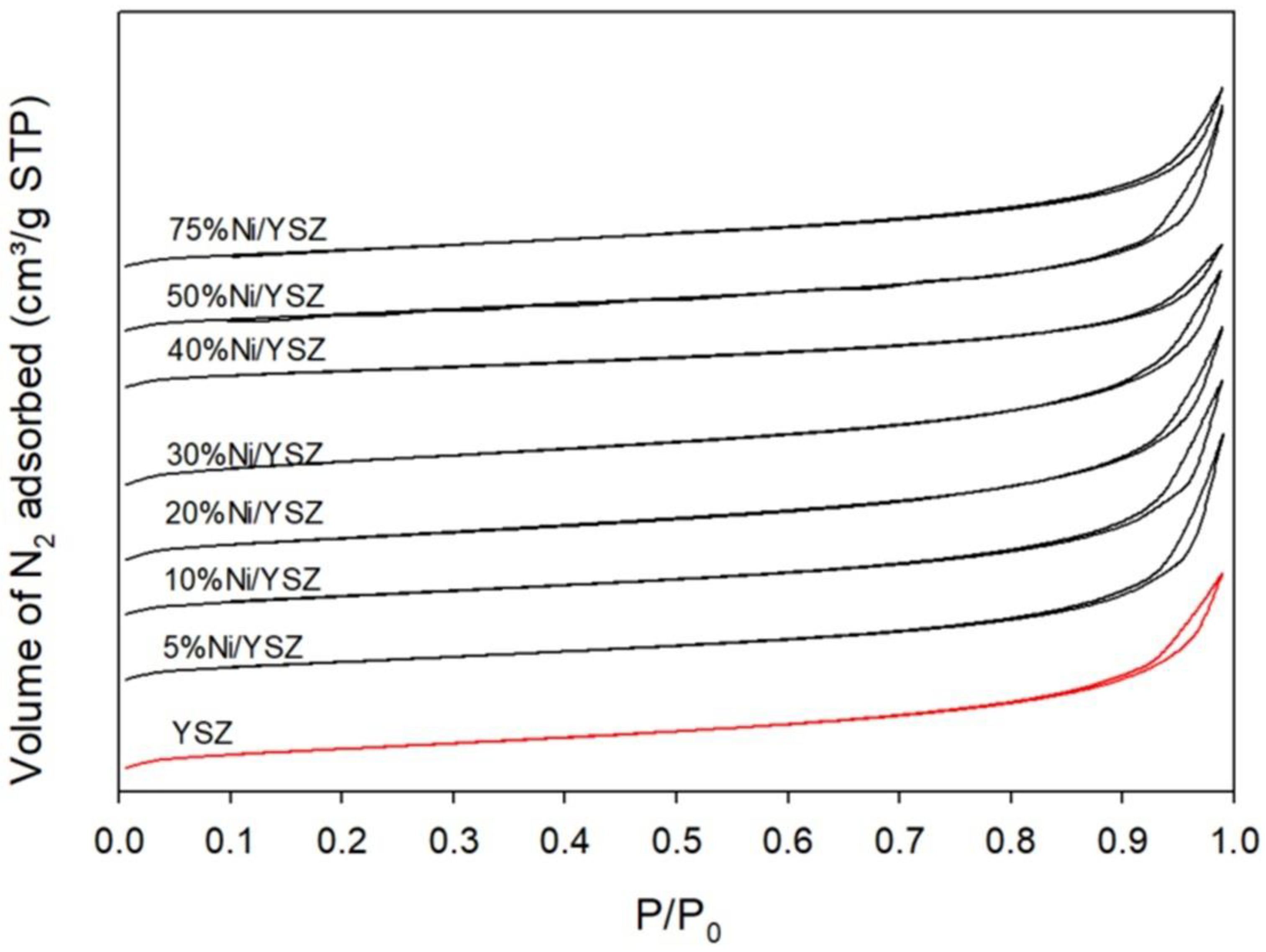
2.1.1. Textural Properties
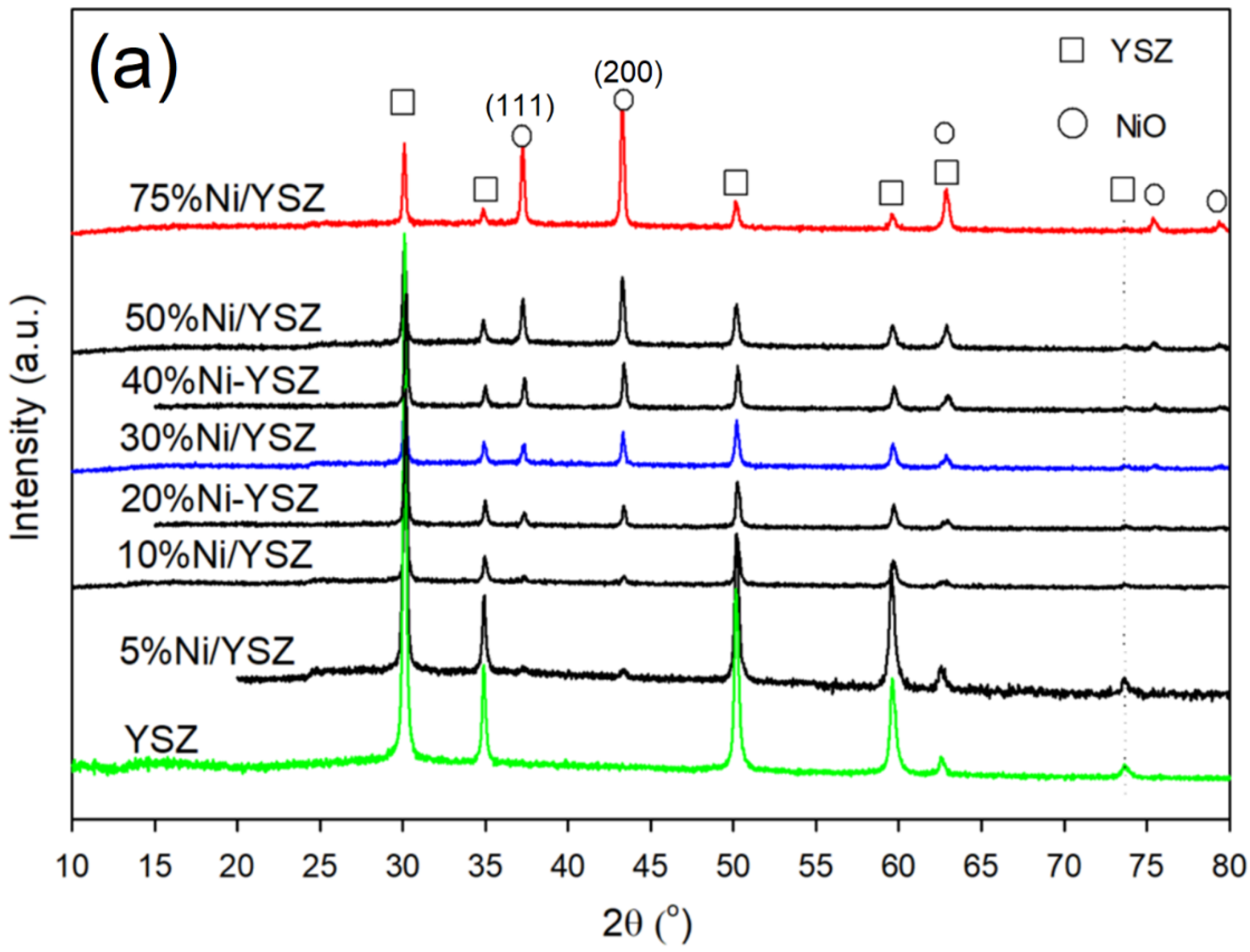
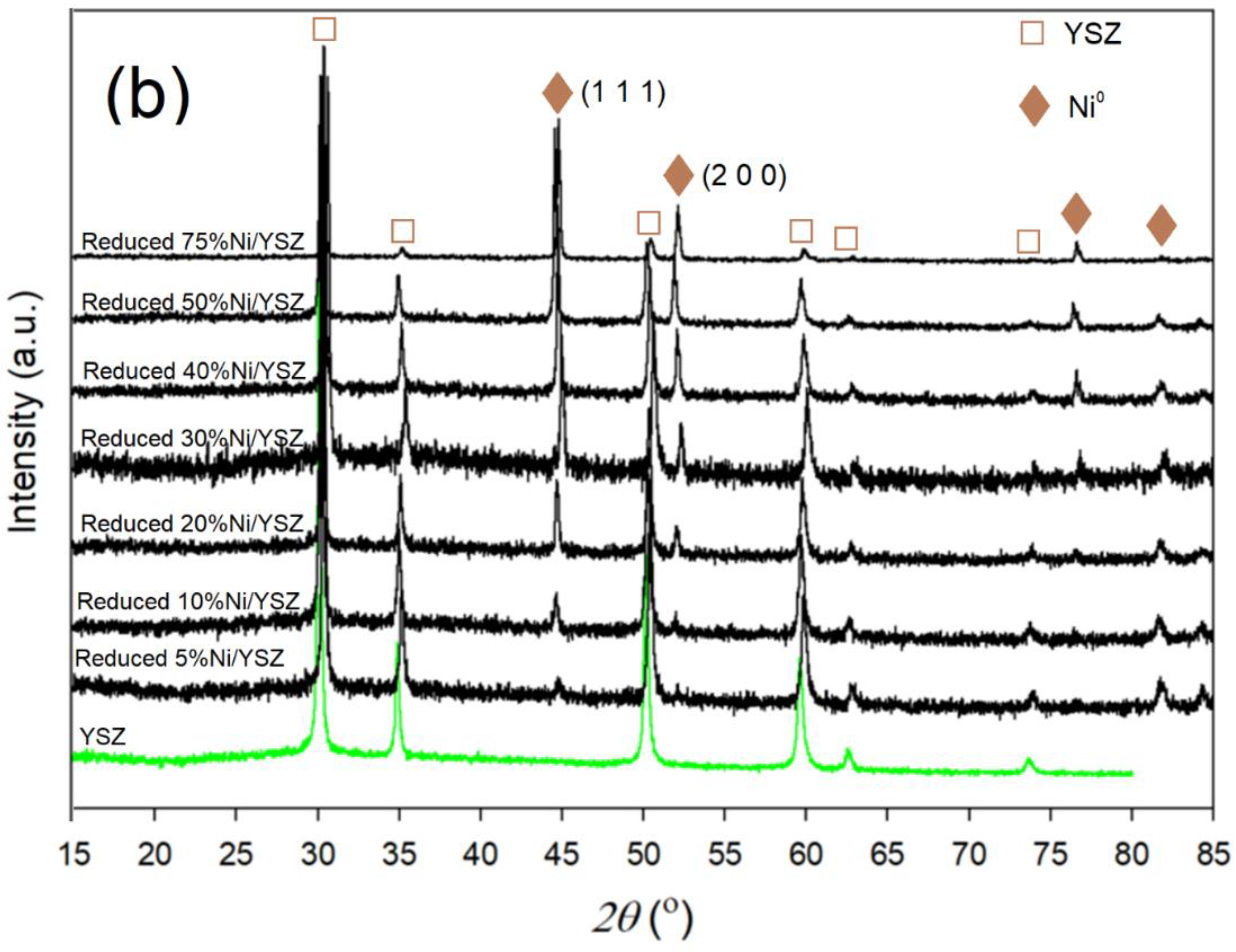
The N2-adsorption/desorption properties of YSZ and the freshly prepared Ni/YSZ catalysts were investigated. Their adsorption curves are presented in Figure 1. As seen in the figure, the adsorption curves of all the samples developed into type-IV isotherms with an H3-type hysteresis loop based on the IUPAC classifications [45,46]. This kind of hysteresis loop is caused by capillary condensation and evaporation at high relative pressures within the range of 0.8 to 1. This N2-adsorption/desorption property is typical for mesoporous materials consisting of slit-shaped pores [47]. In addition, the similarity in the N2-adsorption/desorption isotherms of both the YSZ and Ni/YSZ catalysts revealed that there was no significant alteration in the YSZ support’s framework after the impregnation of Ni. Notwithstanding, there were changes in the BET surface area, pore size and pore volume after the impregnation process as shown in Table 1. The BET surface area initially decreased with increasing Ni content from 5% to 10% and then increased until 30% Ni loading then declined again with high Ni loading of above 40%. The observed decrease in the surface area can be attributed to the partial blockage of the pores due to the dispersion of Ni in the support. Furthermore, the average pore size and pore volume relatively increased with higher Ni loading until 30% Ni loading and decreased above 30% Ni loading.

2.1.2. XRD Analysis

The crystalline phases present in all the catalysts were investigated by powder XRD. The recorded diffractograms of both the freshly prepared and reduced catalysts are shown in Figure 2a,b. The X-ray peaks were matched with the Joint Committee on Powder Diffraction Standards (JCPDS) database [48,49]. The NiO and Ni0 particle sizes were estimated using the Debye–Scherrer equation [50] (Equation (2)):
d p ( nm ) = K λ β cos θ
where dp is the particle size in nm, K is the shape factor with the value of 0.9 (assuming a spherical particle), λ is the X-ray wavelength of the X-ray source Cu Kα (1.5406 Å), β is the line broadening at half the maximum intensity (FWHM) of the NiO or Ni0 diffraction peak and θ is the Bragg angle in radian.
An analysis of the patterns for the freshly prepared catalysts (Figure 2a) indicated the existence of YSZ peaks (JCPDS 81–1550) at 2θ = 29.9° (1 1 1), 34.6° (2 0 0), 50.0° (2 2 0), 59.4° (2 2 2), 62.3° and 73.5° (4 0 0) [44,51]. NiO peaks (JCPDS 73–1519) were observed at 2θ = 37.4°, 43.4°, 75.6° and 79.5° for the 30% Ni, 50% and 75% Ni catalysts, while the NiO peak intensities observed at 2θ = 37.4°, 43.4° and 75.6° for the 5% Ni and 10% Ni catalysts was very weak. In addition, there was an overlap between the YSZ and NiO phases at 2θ = 62.8°. After catalyst reduction in H2, the peak at 2θ = 37.4° disappeared while the peak at 43.4° shifted to around 44.5°–45° indicating the presence of Ni0 metal (Figure 2b). A new peak appeared at about 52°, indicating the presence of Ni0 metal. Furthermore, the particle size calculation using the Scherrer Equation (Equation (5)) showed that there was a relative increase in Ni particle size after the reduction in H2.
This increase in Ni particle size after the reduction of NiO was unexpected. However, the reduction of catalysts at elevated temperatures has been reported to encourage crystal growth through migration and coalescence, or by atom diffusion [52,53,54,55]. Yi et al. [56] employed the atom diffusion mechanism to conduct a sintering kinetic study for the growth of Ni during the reduction of a series of Ni-based catalysts. The authors stated from their findings that the distance between the diffused Ni species and metal-support interactions (MSI) or variation in pore size and shape influenced the order of sintering kinetics of Ni.
Notwithstanding the occurrence of Ni crystal growth, all the reduced catalysts exhibited similar XRD patterns, which indicated that the Ni/YSZ structure was not significantly altered after the reduction process.

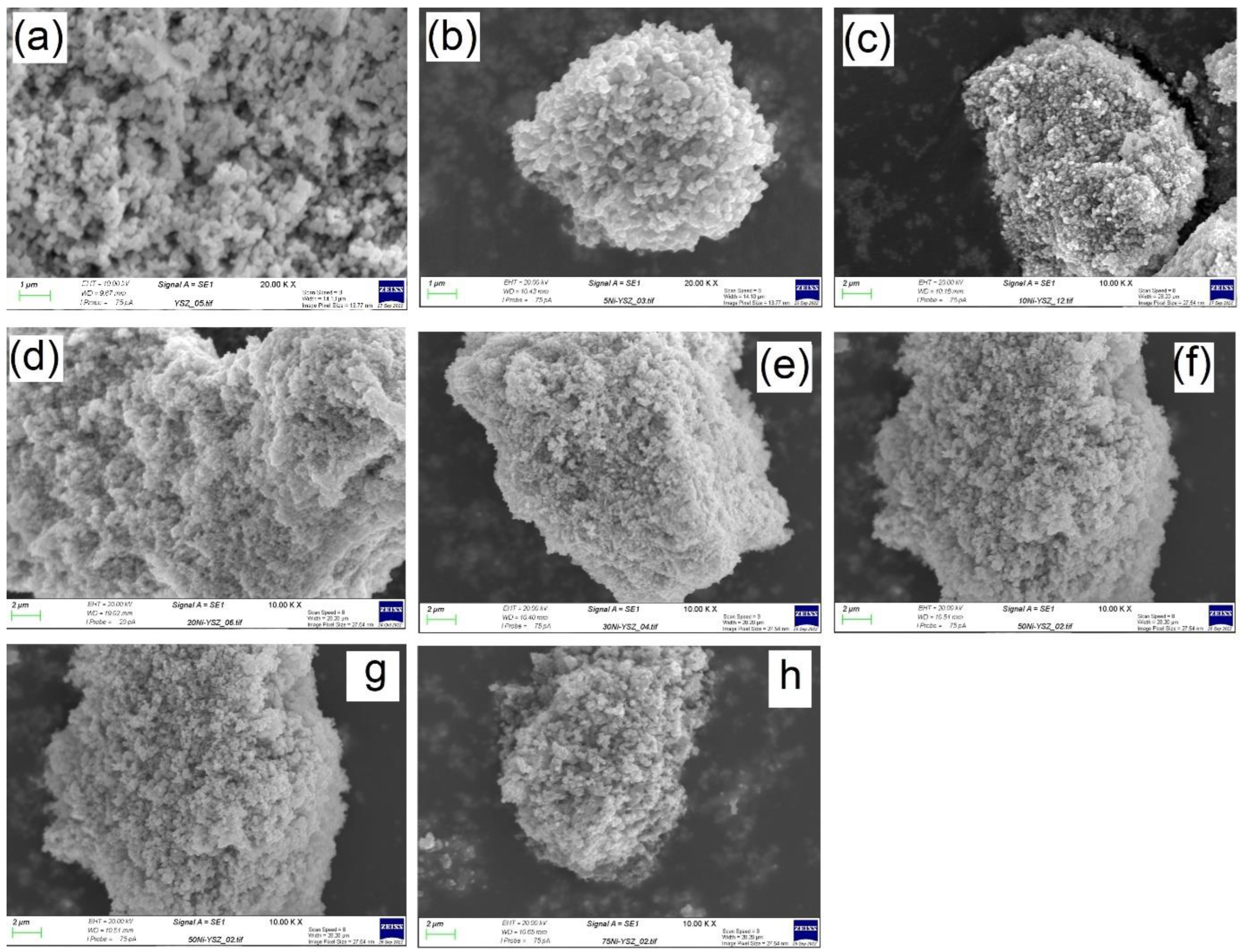
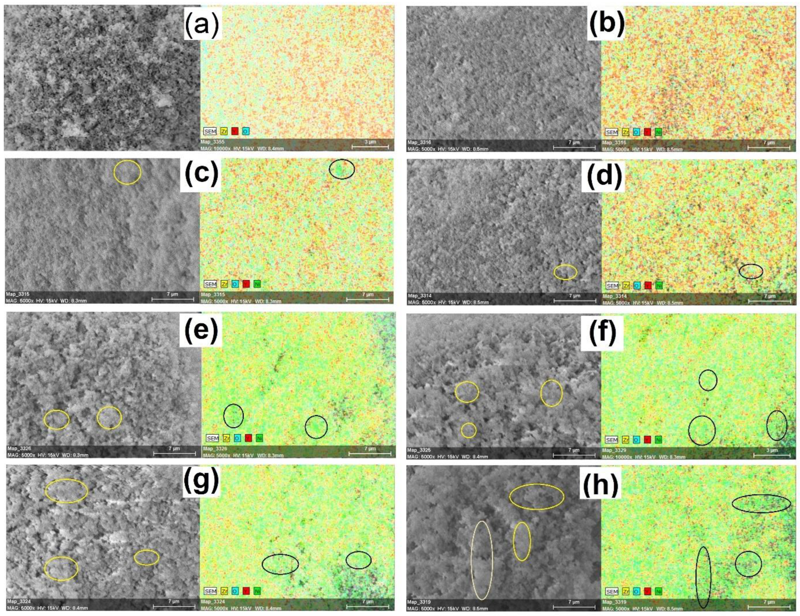
2.1.3. SEM Measurement

The SEM images of the calcined Ni/YSZ catalysts and SEM-EDS elemental mapping of the reduced catalysts are represented in Figure 3 and Figure 4, respectively. The YSZ support (Figure 3a) showed a rough surface with uniform morphology. The SEM image of the 5% Ni/YSZ catalyst Figure 3b showed a uniform surface, which indicates an even distribution of the Ni particles. This even distribution and absence of sintering of the NiO particles were likely due to the low content of NiO particles in relation to the YSZ support’s high surface availability. With increasing Ni content (Figure 3c–f), the clustering of NiO particles became evident, which was in line with the BET analyses.
The EDX mapping of the reduced catalysts shown in Figure 4 gives an insight into how Ni particles are distributed on the catalyst surfaces. The circled regions have a high concentration of Ni (clustering), as indicated by the dense green colour, while the dark spots seen in most of the EDX mapping of the catalysts are due to the cavities resulting from their rough surfaces. At 5% Ni, the Ni particles were well dispersed on the surface. The presence of Ni particles started becoming more visible as the loading increased from 10% to 75%. However, the mappings of the catalysts with higher Ni loadings from 30% to 75% showed an uneven distribution of Ni particles. In addition, the regions showing the presence of Ni clusters (dense green colour) also increased with the Ni loading. These results further support other analyses indicating the occurrence of significant sintering at higher Ni-loading.

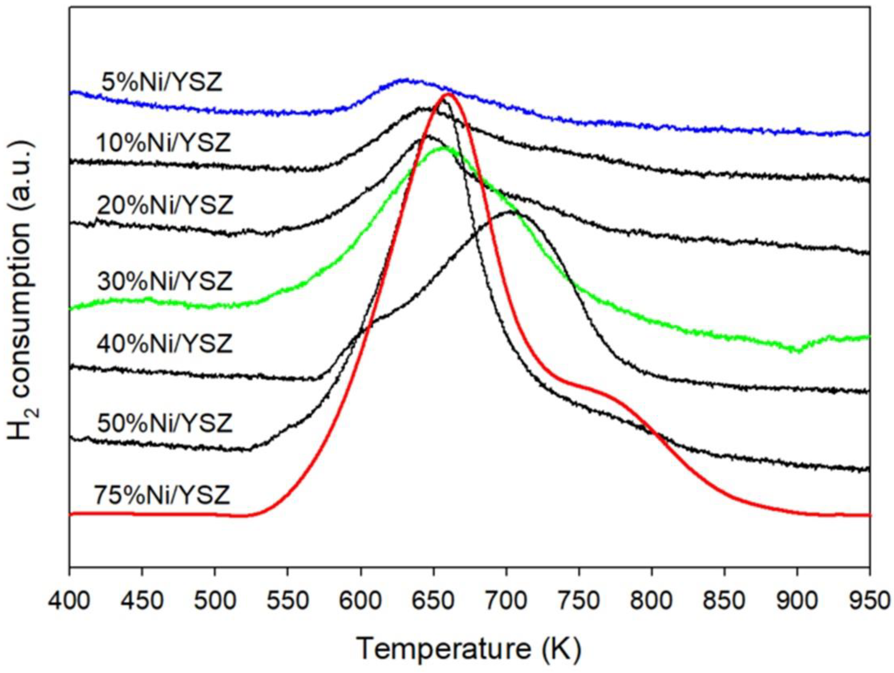
2.1.4. Catalyst Reducibility

The reduction behaviour of all the catalysts was investigated using the TPR-MS technique in the H2(20%)/N2 environment. The TPR profiles of the catalysts are shown in Figure 5. Generally, when the reduction of a catalyst in the H2 environment begins, the amount of hydrogen in the system will start dropping (increase in H2 consumption). The increase in H2 consumption will continue until a maximum point is reached, and then the signal will start decreasing. The temperature at which the maximum point is reached normally is used to identify the reduction temperature of a catalyst. Therefore, the reduction temperatures of the catalysts in this study were determined by the readings at the maximum peaks from the H2-TPR profile. As seen in the figure, both the 5% Ni and 10% Ni loading exhibited similar behaviour at temperatures ranging from 567 to 810 K. Meanwhile the reduction of 30% Ni, 50% and 75% Ni catalysts was in the range of 520 to 860 K. The reduction peak temperatures for all the catalysts are given in Table 2. The first peak observed at lower temperatures for all the catalysts can be attributed to the reduction of bulk NiO with weak support interaction to Ni0, while the second peak at higher temperatures can be ascribed to the reduction of the highly dispersed NiO particles with stronger MSI [57,58]. These results revealed that higher Ni loading of around 30–40% decreased the reducibility of the catalysts as seen in the shift in the reduction peaks to the right and enlarged peak 2, which means that a higher temperature is required for the complete reduction of the NiO particles. This indicated higher interaction with the support and was in line with the BET results. A further increase in Ni loading to 50 to 75% resulted in an increase in Ni with low MSI and a reduction of Ni at a lower temperature, as indicated by enlarged peak 1 (Figure 4). This confirmed the BET and XRD results and the formation of large Ni particles with low MSI.
The reduction of all the catalysts was completed before reaching 973 K. Therefore, 973 K was selected as the catalyst reduction temperature to ensure that no NiO was taking part in the reaction during the activity testing.

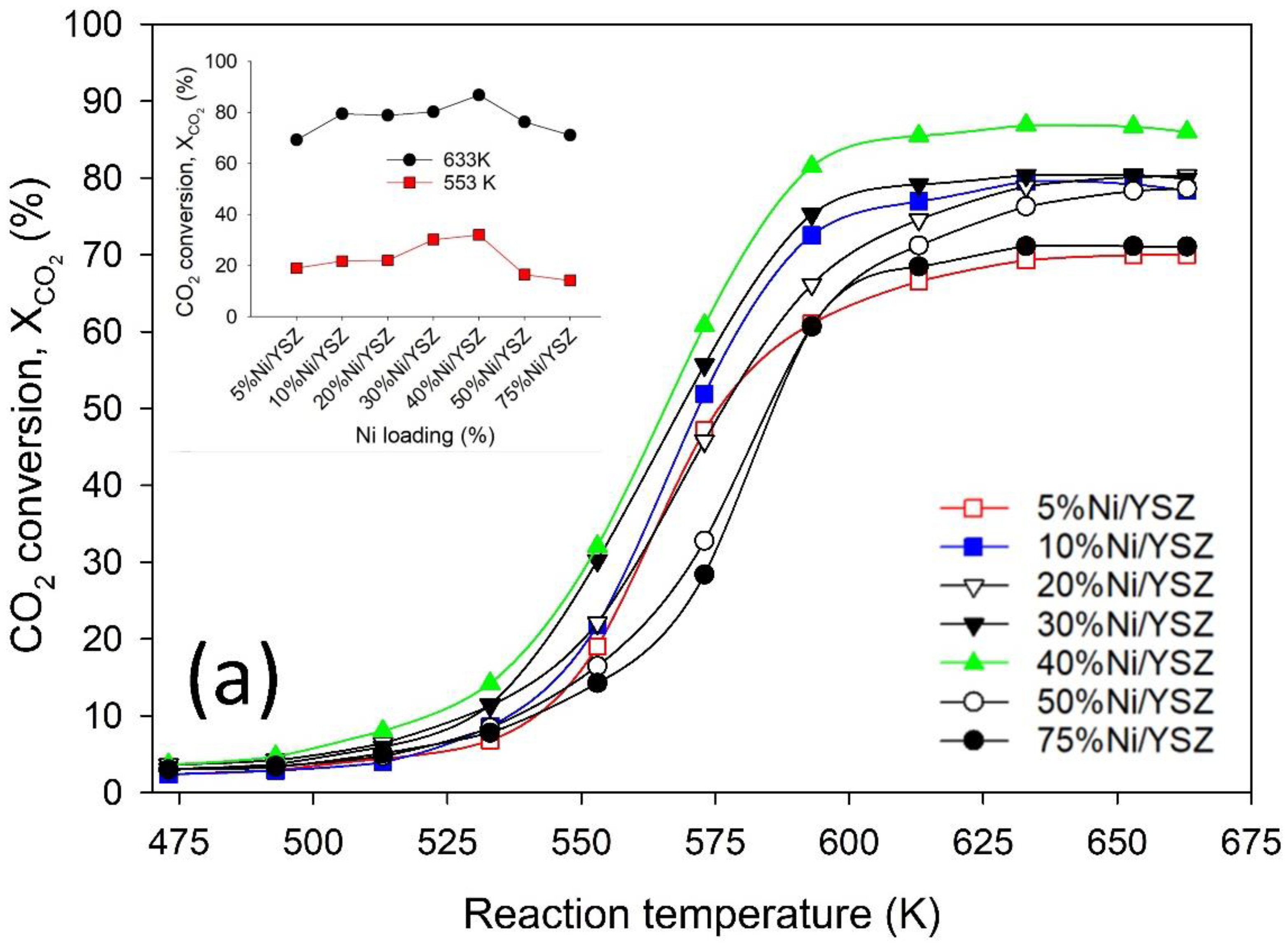
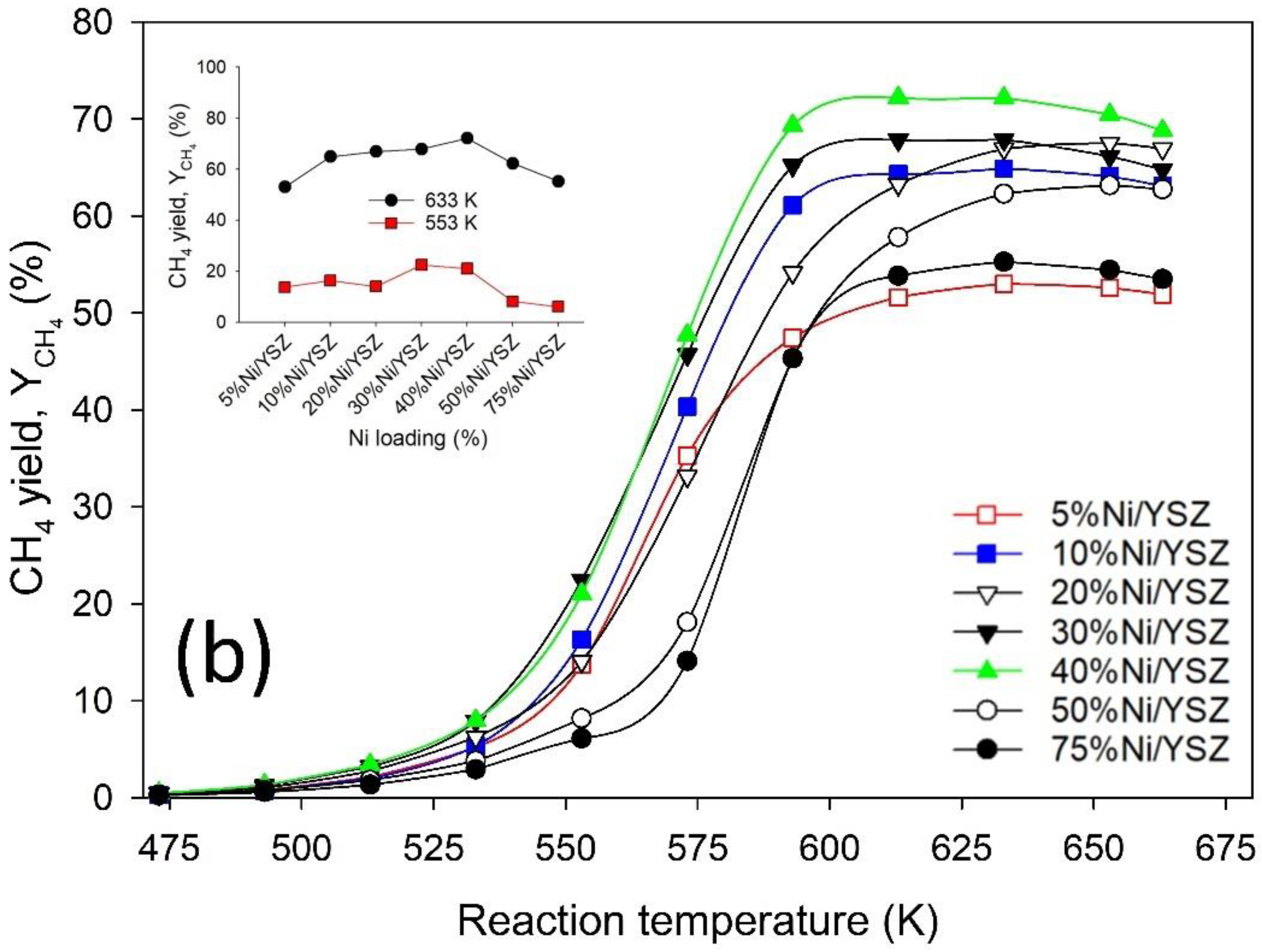
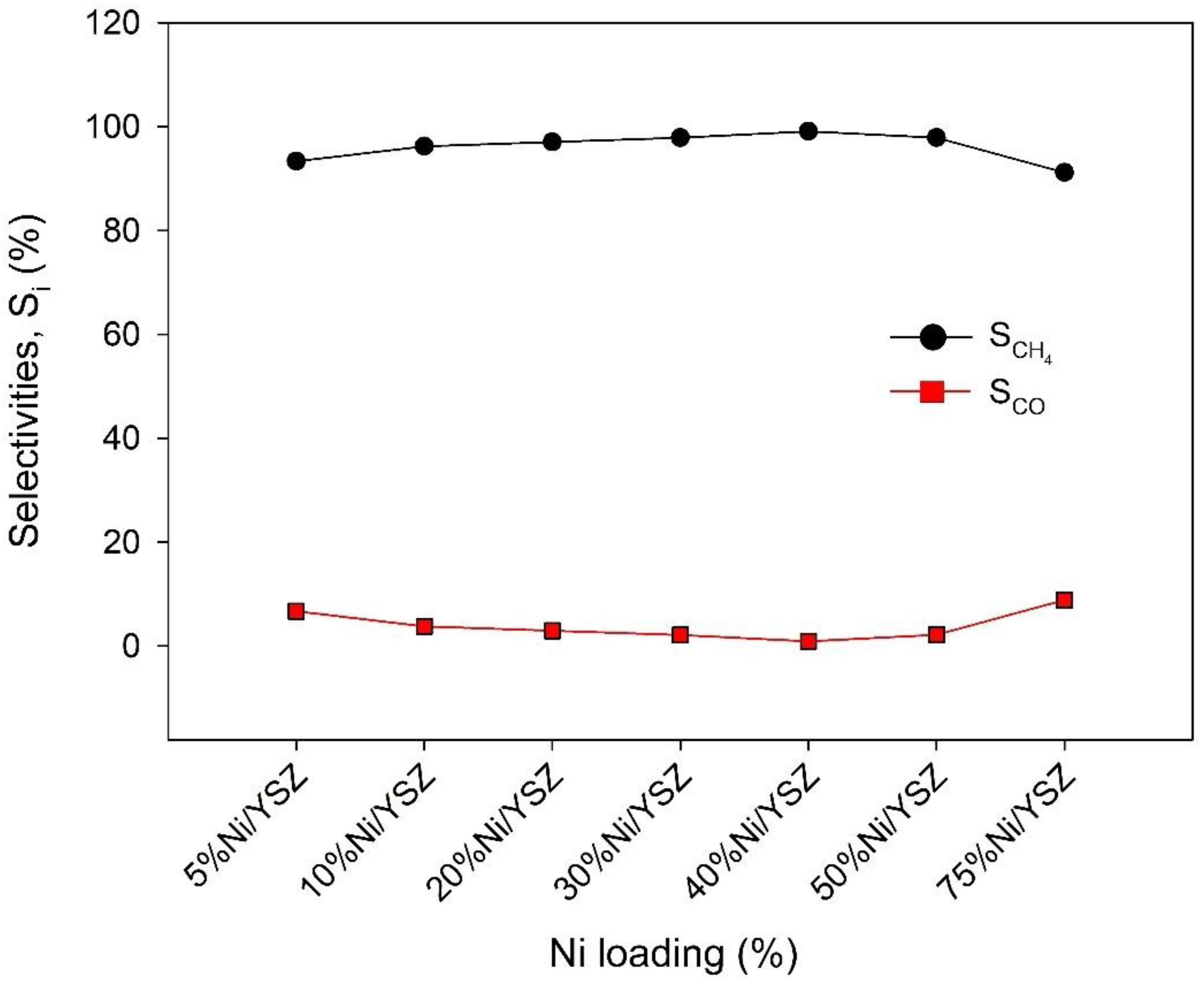
2.2. Catalyst Activity Test

The results of the activity test over the Ni/YSZ catalysts during CO2 methanation are shown in Figure 6a,b. As seen in Figure 6a, there was a steady but low XCO2 at temperatures between 473 to 553 K. However, beyond 553 K a sharp increase in the CH4 formation was observed. The increase in XCO2 continued with increasing temperature until around 633 K for all tested catalysts. Thereafter, the XCO2 declined slowly at higher temperatures. Therefore, the optimal temperature for XCO2 was from 613 to 653 K. All the catalysts exhibited relatively high activity at the optimal temperature. These superior properties of the catalysts are likely related to the unique physicochemical properties of the YSZ support which include the presence of defect sites such as the oxygen vacancies [28,29]. These properties aid the adsorption and activation of CO2 [30] which is a crucial step in the mechanism of CH4 formation during the CO2 methanation reaction.
In Figure 6b, a similar trend was observed for YCH4, where the amount of CH4 produced was initially favoured as the temperature increased, and then decreased when the temperature was raised above the optimum value. It is worth noting that the CO2 methanation reaction is thermodynamically feasible at low temperatures due to its exothermic nature (see Figure 7), but the results from this study revealed that high YCH4 cannot be achieved at low temperatures. This is due to the substantial kinetic limitations associated with the cleavage of CO2 bonds during its reduction processes to produce other carbon species, which leads to the formation of CH4 [59,60]. Mebrahtu et al. [61] acknowledged that the CO2 methanation reaction is thermodynamically feasible at low temperatures, but the authors stated that high operating pressures will be required to conduct CO2 methanation at low temperatures for a favourable equilibrium composition.
On the other hand, conducting CO2 methanation at elevated reaction temperatures favours side reactions such as CH4 dry reforming (Equation (3)), CH4 steam reforming (Equation (4)), reverse-Boudouard (Equation (5)), and RWGS reactions (Equation (6)), which usually causes low YCH4 [60,62].
CO 2 + CH 4 2 CO + 2 H 2     Δ H 298 K = 247.3   kJ   mol 1
CH 4 + H 2 O CO 2 + 3 H 2     Δ H 298 K = 206   kJ   mol 1
CO 2 + C 2 CO     Δ H 298 K = 172.4   kJ   mol 1
CO 2 + H 2 CO + H 2 O     Δ H 298 K = 41.2   kJ   mol 1
The occurrence of these side reactions most likely was responsible for the observed steady and slow decrease in XCO2 at temperatures above the optimum value of 650 K, since CO2 was consumed during most of these reactions while the decline in YCH4 was visible. Moreover, the exothermic nature of the CO2 methanation reaction and the likelihood of hot-spot formation makes it difficult to control the heat in the reactor. Razzaq et al. [63] reported that instead of the YCH4 increasing at high temperatures, CO formation via RWGS reaction was favoured at temperatures above 673 K. Similarly, Panagiotopoulou et al. [64] observed that at reaction temperatures greater than 633 K, the formation rate of CO through RWGS was greater than the rate at which CO was consumed in the hydrogenation reaction, which in total led to the decrease in CO conversion.
The catalyst performance improved as the Ni loading increased until reaching optimal performance for a loading of 40% Ni. Any further increase in Ni loading reduced the catalyst activity for the methanation reaction. The initial increase in the catalyst’s activity with Ni loading can be ascribed to more availability of active sites resulting from the improved pore size as seen in the BET results (see Table 1) and the improvement in MSI as seen in their reducibility at lower temperatures (see Figure 5). Figure 8 reveals that the increase in Ni loading resulted in a decrease in CO selectivity up to 40% Ni loading. Studies have shown that Ni loading, together with Ni0 particle size and morphology, influences the reaction pathways during CO2 methanation owing to its role in the adsorption and activation of H2 on the catalyst surface [65]. Small Ni0 particle size will likely encourage a longer adsorption-dissociation route through which CH4 or C is formed. The small Ni0 particles may also have low coverage for H2 dissociation which favours the desorption of CO from the surface without hydrogenation to CH4 [44,66].
Meanwhile, large Ni0 particle size can influence the intermediate carbon species to be hydrogenated to CH4 since there is a large coverage for H2. This means more CH4 production and less CO formation. Accordingly, the decrease in CO selectivity was observed as shown in Figure 8. can be attributed to the favoured reaction route towards the formation of CH4 as the Ni content increases. Other studies have also shown that an increase in Ni loading encourages H2 chemisorption and increased H2 uptake, indicating high H2 coverage on the catalyst surface [66,67]. However, too high Ni loading of over 40% affects the catalyst morphology reducing the overall catalyst activity.
From our results, the catalyst performance significantly declined after increasing the Ni% loading beyond 40%. This indicates that there was likely a change in the reaction path at higher Ni loading or inaccessibility of the reacting species to the active sites due to pore blockage. In any case, further study is required to determine the relationship between Ni loading and the number of active sites, as well as the optimum Ni0 particle size that favours high CH4 production and minimises or inhibits CO formation. Overall, the performance of the catalysts was in the order 40% Ni/YSZ > 30% Ni/YSZ > 20% Ni/YSZ > 50% Ni/YSZ > 10% Ni/YSZ > 5% Ni/YSZ > 75% Ni/YSZ at temperatures beyond 613 K. Therefore, the optimum catalyst choice was 40% Ni/YSZ. It is worth mentioning that this comparative study was carried out using an equal mass of catalysts. We also found that the catalyst bed length in the reactor increased with higher Ni loading, indicating an increase in the volume and a decrease in the bulk density. This means that the Ni/YSZ catalysts at higher Ni loading would likely have a longer contact time for the reacting species to react than the catalysts at low Ni loading. The longer contact time may also explain why there was an improvement in the performance with higher Ni loading.
However, the catalyst activity dropped when the loading was increased beyond 40% Ni despite a favoured higher contact time. This is likely due to the enhanced clustering of the Ni particles as seen in the SEM images and the increase in the crystallite size at higher Ni loading (see Table 1).

3. Materials and Methods

3.1. Catalyst Synthesis

Ni-based yttria stabilised zirconia, Ni/YSZ was prepared by wetness impregnation of YSZ (YSZ: Tosoh-zirconia TZ-8YS, from Tosoh corporation, Tokyo, Japan) with an aqueous solution of nickel(II) nitrate hexahydrate (Ni(NO3)2·6H2O Extra Pure, SLR, from Fisher Chemical™, Waltham, MA, USA). In a typical synthesis, the calculated weight of YSZ powder was added to an aqueous solution containing a calculated concentration of Ni(NO3)2·6H2O (to achieve various Ni loading) and stirred at 500 rev min−1 and 303 K temperature for 2 h. Thereafter, the temperature was raised to 323 K while the mixture remained under stirring until a slurry was formed. The mixture was then transferred to an oven where it was dried overnight at 353 K and calcined at 923 K for 3 h.

3.2. Catalyst Characterisation

The BET surface area of the samples was measured via N2 adsorption using a Micromeritics® TriStar II Plus analyser at a temperature of 77.15 K. Before the analysis, the samples were degassed for 6 h at 373 K under vacuum. Powder X-ray diffraction of all the samples was carried out in a Proto Benchtop AXRD at 30.5 kV and 20.5 mA scanning from a 2-theta of 5° to 80° at an increment of 0.0149° using Cu-Kα with wavelength 1.5406 Å. An environmental Scanning Electron Microscope (SEM) Zeiss Evo10 and Tabletop electron microscope Hitachi TM3030 with an energy dispersive spectrometer (EDS) were used to take images and view the distribution of the various species on the catalyst surfaces through mapping. The reducibility of samples was determined through H2-temperature programmed reduction (TPR) in a quartz tube reactor connected to an MKS Cirrus mass spectrometer.

3.3. Catalyst Testing

The performance of the synthesised catalysts for the CO2 methanation was examined in a continuous flow quartz tube fixed-bed reactor (I.D. = 5.5 mm, wall thickness = 2 mm) at a temperature range of 473–703 K under atmospheric pressure. In a typical test, 200 mg of the catalyst was loaded into the reactor containing inert quartz wool at both ends of the catalyst. The reactor was horizontally positioned in a temperature-controlled furnace (Elite Thermal Systems. Ltd.: Model THH12/90/305, Market Harborough, UK). Before the reaction, a catalyst was first reduced by passing a stream of 20 mL min−1 H2 and 60 mL min−1 N2 through it at 923 K for 1.5 h. Subsequently, the reactor was cooled to the reaction temperature of 473 K and the catalyst was purged by passing a stream of N2 (100 mL min−1) for 5 min. Thereafter, a gaseous feed stream containing N2 (60 mL min−1), H2 (60 mL min−1) and CO2 (15 mL min−1) was introduced at 473 K under atmospheric pressure and the temperature was increased gradually up to 693 K. The reactant flow rate was controlled using calibrated mass flow controllers. The product of the reaction was channelled through a drying system before being sent to a gas chromatograph (GC) Shimadzu GC-2014 for analysis. The GC, which was equipped with a thermal conductivity detector and a column (ShimCarbon ST, length 200 m, inner diameter 0.35 mm), was operated under argon as the carrier gas. The catalyst activities were estimated by applying Equations (7)–(9) [68], respectively:
X CO 2 = ( F CO 2 , in F CO 2 , out F CO 2 , in ) × 100 %
S i = ( F i , out F CH 4 , out + F CO , out ) × 100 %
Y CH 4 = ( X CO 2 × S CH 4 100 ) %
where XCO2 = CO2 conversion, Si = Selectivity of product i (CO or CH4), YCH4 = CH4 yield, F CO 2 , in = molar flowrate of inlet CO2 in mol/s, F C O 2 , out = flowrate of unreacted CO2 in product and F C H 4 , out is the molar flowrate of CH4 in the product, F i , out is the molar flowrate of CH4 or CO in the product.

4. Conclusions

The effect of Ni loading on the catalytic activity of Ni/YSZ catalysts during CO2 methanation was studied. The Ni/YSZ catalysts were prepared by the wetness impregnation method with variations in the amount of Ni content. The N2 adsorption/desorption isotherms of these catalysts revealed that they were formed in a type IV isotherm with an H3-type hysteresis loop which confirms the presence of mesopores and micropores in their structures. The similarity in the isotherms of all the catalysts, regardless of the amount of Ni content, suggests that the YSZ structure was preserved after the catalyst preparation. XRD results indicated that higher Ni loading favoured the formation of larger Ni particle sizes as obtained from the Scherrer equation. The EDX mapping of these catalysts further revealed the presence of more clusters at higher Ni loading. The reducibility test showed that the increase in Ni loading caused the reduction temperature to shift to the right. This suggests that a higher temperature is required to reduce the catalysts with higher Ni loading as a result of strong MSI. An activity test of these catalysts at different temperatures from 473 to 663 K was carried out. The results showed that both CO2 conversion and CH4 yield were favoured with an increase in temperature until an optimum temperature of around 613 to 653 K, beyond which there was a decline in the activity. The decrease in activity at the elevated temperatures beyond the optimum value was ascribed to the occurrence of side reactions, which are favoured at higher temperatures. It was also found that the catalyst performance did not increase proportionately with Ni loading. The amount of Ni in the catalyst was increased from 5% to 75% and the optimum loading was found to be between 30% and 40% Ni loading. The improved catalyst performance with higher Ni loading was ascribed to the increase in coverage for H2 adsorption and activation. We also noted that the bed length was longer for the catalysts with higher Ni loading and this encouraged higher contact time. However, the catalyst activity dropped as the Ni loading increased beyond 40% Ni. Therefore, further study is recommended to determine how the variation in Ni loading influences the number of active sites. This will help to fully understand the mechanism of the reactions during CO2 methanation over Ni/YSZ at different Ni loadings.

Author Contributions

Conceptualization: O.O., A.E.-k. and R.S.-W.; writing—original draft: O.O.; investigation: O.O. and A.J.M.; methodology: A.J.M. and A.E.-k.; formal analysis: A.J.M. and A.E.-k.; data curation: A.J.M.; validation: A.E.-k.; supervision: R.S.-W.; writing—review & editing: R.S.-W. All authors have read and agreed to the published version of the manuscript.

Funding

This research was funded by Petroleum Technology Development Fund (grant number: 18UK/PHD/025).

Institutional Review Board Statement

Not applicable.

Informed Consent Statement

Not applicable.

Data Availability Statement

Not applicable.

Acknowledgments

The authors acknowledged financial support provided by the Petroleum Technology Development Fund (grant number: 18UK/PHD/025) for undertaking this current study.

Conflicts of Interest

The authors declare no conflict of interest.

References

  1. U.S. Energy Information Administration. International Energy Outlook 2021. Analysis & Projections. 2021. Available online: https://www.eia.gov/outlooks/ieo/consumption/sub-topic-01.php (accessed on 3 November 2021).
  2. NBC. News Greenhouse Gas Levels Hit a New Record, Cuts Fall Short, U.N. Finds. Climate in Crisis. 2021. Available online: https://www.nbcnews.com/science/environment/greenhouse-gas-levels-hit-new-record-cuts-fall-short-un-finds-rcna3728 (accessed on 3 November 2021).
  3. Barbera, E.; Mantoan, F.; Bertucco, A.; Bezzo, F. Hydrogenation to convert CO2 to C1 chemicals: Technical comparison of different alternatives by process simulation. Can. J. Chem. Eng. 2020, 98, 1893–1906. [Google Scholar] [CrossRef]
  4. Wang, S.; Tarroja, B.; Schell, L.S.; Shaffer, B.; Samuelsen, S. Prioritizing among the end uses of excess renewable energy for cost-effective greenhouse gas emission reductions. Appl. Energy 2019, 235, 284–298. [Google Scholar] [CrossRef]
  5. Chauvy, R.; Verdonck, D.; Dubois, L.; Thomas, D.; De Weireld, G. Techno-economic feasibility and sustainability of an integrated carbon capture and conversion process to synthetic natural gas. J. CO2 Util. 2021, 47, 101488. [Google Scholar] [CrossRef]
  6. Salomone, F.; Giglio, E.; Ferrero, D.; Santarelli, M.; Pirone, R.; Bensaid, S. Techno-economic modelling of a Power-to-Gas system based on SOEC electrolysis and CO2 methanation in a RES-based electric grid. Chem. Eng. J. 2019, 377, 120233. [Google Scholar] [CrossRef]
  7. Hussain, I.; Jalil, A.A.; Izan, S.M.; Azami, M.S.; Kidam, K.; Ainirazali, N.; Ripin, A. Thermodynamic and experimental explorations of CO2 methanation over highly active metal-free fibrous silica-beta zeolite (FS@SiO2-BEA) of innovative morphology. Chem. Eng. Sci. 2021, 229, 116015. [Google Scholar] [CrossRef]
  8. Beuls, A.; Swalus, C.; Jacquemin, M.; Heyen, G.; Karelovic, A.; Ruiz, P. Methanation of CO2: Further insight into the mechanism over Rh/γ-Al2O3 catalyst. Appl. Catal. B Environ. 2012, 113–114, 2–10. [Google Scholar] [CrossRef]
  9. Gao, J.; Liu, Q.; Gu, F.; Liu, B.; Zhong, Z.; Su, F. Recent advances in methanation catalysts for the production of synthetic natural gas. RSC Adv. 2015, 5, 22759–22776. [Google Scholar] [CrossRef]
  10. González-Castaño, M.; de Miguel, J.C.N.; Penkova, A.; Centeno, M.A.; Odriozola, J.A.; Arellano-Garcia, H. Ni/YMnO3 perovskite catalyst for CO2 methanation. Appl. Mater. Today 2021, 23, 101055. [Google Scholar] [CrossRef]
  11. Duyar, M.S.; Treviño, M.A.A.; Farrauto, R.J. Dual function materials for CO2 capture and conversion using renewable H2. Appl. Catal. B Environ. 2015, 168–169, 370–376. [Google Scholar] [CrossRef]
  12. Zhao, K.; Li, Z.; Bian, L. CO2 methanation and co-methanation of CO and CO2 over Mn-promoted Ni/Al2O3 catalysts. Front. Chem. Sci. Eng. 2016, 10, 273–280. [Google Scholar] [CrossRef]
  13. Ahn, J.Y.; Chang, S.W.; Lee, S.M.; Kim, S.S.; Chung, W.J.; Lee, J.C.; Cho, Y.J.; Shin, K.S.; Moon, D.H.; Nguyen, D.D. Developing Ni-based honeycomb-type catalysts using different binary oxide-supported species for synergistically enhanced CO2 methanation activity. Fuel 2019, 250, 277–284. [Google Scholar] [CrossRef]
  14. Lin, J.; Ma, C.; Wang, Q.; Xu, Y.; Ma, G.; Wang, J.; Wang, H.; Dong, C.; Zhang, C.; Ding, M. Enhanced low-temperature performance of CO2 methanation over mesoporous Ni/Al2O3-ZrO2 catalysts. Appl. Catal. B Environ. 2019, 243, 262–272. [Google Scholar] [CrossRef]
  15. Karelovic, A.; Ruiz, P. Improving the hydrogenation function of Pd/γ-Al2O3 catalyst by Rh/γ-Al2O3 Addition in CO2 methanation at low temperature. ACS Catal. 2013, 3, 2799–2812. [Google Scholar] [CrossRef]
  16. Younas, M.; Loong Kong, L.; Bashir, M.J.K.; Nadeem, H.; Shehzad, A.; Sethupathi, S. Recent Advancements, Fundamental Challenges, and Opportunities in Catalytic Methanation of CO2. Energy Fuels 2016, 30, 8815–8831. [Google Scholar] [CrossRef]
  17. Nizio, M.; Albarazi, A.; Cavadias, S.; Amouroux, J.; Galvez, M.E.; Da Costa, P. Hybrid plasma-catalytic methanation of CO2 at low temperature over ceria zirconia supported Ni catalysts. Int. J. Hydrogen Energy 2016, 41, 11584–11592. [Google Scholar] [CrossRef]
  18. Lee, C.J.; Lee, D.H.; Kim, T. Enhancement of methanation of carbon dioxide using dielectric barrier discharge on a ruthenium catalyst at atmospheric conditions. Catal. Today 2017, 293–294, 97–104. [Google Scholar] [CrossRef]
  19. Ab Halim, A.Z.; Ali, R.; Bakar, W.A.W.A. CO2/H2 methanation over M*/Mn/Fe-Al2O3 (M*: Pd, Rh, and Ru) catalysts in natural gas; optimization by response surface methodology-central composite design. Clean Technol. Environ. Policy 2015, 17, 627–636. [Google Scholar] [CrossRef]
  20. Kustov, A.L.; Frey, A.M.; Larsen, K.E.; Johannessen, T.; Nørskov, J.K.; Christensen, C.H. CO methanation over supported bimetallic Ni-Fe catalysts: From computational studies towards catalyst optimization. Appl. Catal. A Gen. 2007, 320, 98–104. [Google Scholar] [CrossRef]
  21. Liu, Q.; Yang, H.; Dong, H.; Zhang, W.; Bian, B.; He, Q.; Yang, J.; Meng, X.; Tian, Z.; Zhao, G. Effects of preparation method and Sm2O3 promoter on CO methanation by a mesoporous NiO-Sm2O3/Al2O3 catalyst. New J. Chem. 2018, 42, 13096–13106. [Google Scholar] [CrossRef]
  22. Yan, X.; Liu, Y.; Zhao, B.; Wang, Z.; Wang, Y.; Liu, C. Methanation over Ni/SiO2: Effect of the catalyst preparation methodologies. Int. J. Hydrogen Energy 2013, 38, 2283–2291. [Google Scholar] [CrossRef]
  23. Liu, Q.; Tian, Y. One-pot synthesis of NiO/SBA-15 monolith catalyst with a three-dimensional framework for CO2 methanation. Int. J. Hydrogen Energy 2017, 42, 12295–12300. [Google Scholar] [CrossRef]
  24. Mota, F.M.; Kim, D.H. From CO2 methanation to ambitious long-chain hydrocarbons: Alternative fuels paving the path to sustainability. Chem. Soc. Rev. 2019, 48, 205–259. [Google Scholar] [CrossRef]
  25. Abate, S.; Mebrahtu, C.; Giglio, E.; Deorsola, F.; Bensaid, S.; Perathoner, S.; Pirone, R.; Centi, G. Catalytic Performance of γ-Al2O3-ZrO2-TiO2-CeO2 Composite Oxide Supported Ni-Based Catalysts for CO2 Methanation. Ind. Eng. Chem. Res. 2016, 55, 4451–4460. [Google Scholar] [CrossRef]
  26. Cheng, C.; Shen, D.; Xiao, R.; Wu, C. Methanation of syngas (H2/CO) over the different Ni-based catalysts. Fuel 2017, 189, 419–427. [Google Scholar]
  27. Moghaddam, S.V.; Rezaei, M.; Meshkani, F.; Daroughegi, R. Synthesis of nanocrystalline mesoporous Ni/Al2O3–SiO2 catalysts for CO2 methanation reaction. Int. J. Hydrogen Energy 2018, 43, 19038–19046. [Google Scholar] [CrossRef]
  28. Jia, X.; Zhang, X.; Rui, N.; Hu, X.; Liu, C. jun Structural effect of Ni/ZrO2 catalyst on CO2 methanation with enhanced activity. Appl. Catal. B Environ. 2019, 244, 159–169. [Google Scholar] [CrossRef]
  29. Alves, L.M.N.C.; Almeida, M.P.; Ayala, M.; Watson, C.D.; Jacobs, G.; Rabelo-Neto, R.C.; Noronha, F.B.; Mattos, L.V. CO2 methanation over metal catalysts supported on ZrO2: Effect of the nature of the metallic phase on catalytic performance. Chem. Eng. Sci. 2021, 239, 116604. [Google Scholar] [CrossRef]
  30. Ilsemann, J.; Murshed, M.M.; Gesing, T.M.; Kopyscinski, J.; Bäumer, M. On the support dependency of the CO2 methanation—Decoupling size and support effects. Catal. Sci. Technol. 2021, 11, 4098–4114. [Google Scholar] [CrossRef]
  31. Kouva, S.; Honkala, K.; Lefferts, L.; Kanervo, J. Review: Monoclinic zirconia, its surface sites and their interaction with carbon monoxide. Catal. Sci. Technol. 2015, 5, 3473–3490. [Google Scholar] [CrossRef]
  32. Fan, Z.; Wang, Y.; Zhang, Y.; Liu, J. Influence of oxygen vacancy compensation on the structure, electronic and mechanical properties of yttrium stabilized tetragonal zirconia. Mater. Sci. Semicond. Process. 2021, 135, 106082. [Google Scholar] [CrossRef]
  33. Najafi, S.; Soltanali, S.; Nazemi, A.H. Effect of Synthesis Parameters on Zirconia Phases: Tetragonal or Monoclinic? ECS J. Solid State Sci. Technol. 2021, 10, 043003. [Google Scholar] [CrossRef]
  34. Kalita, P.; Ghosh, S.; Gutierrez, G.; Rajput, P.; Grover, V.; Sattonnay, G.; Avasthi, D.K. Grain size effect on the radiation damage tolerance of cubic zirconia against simultaneous low and high energy heavy ions: Nano triumphs bulk. Sci. Rep. 2021, 11, 10886. [Google Scholar] [CrossRef] [PubMed]
  35. Comba, A.; Baldi, A.; Tempesta, R.M.; Carossa, M.; Perrone, L.; Saratti, C.M.; Rocca, G.T.; Femiano, R.; Femiano, F.; Scotti, N. Do chemical-based bonding techniques affect the bond strength stability to cubic zirconia? Materials 2021, 14, 3920. [Google Scholar] [CrossRef] [PubMed]
  36. de Souza, E.F.; Appel, L.G. Oxygen vacancy formation and their role in the CO2 activation on Ca doped ZrO2 surface: An ab-initio DFT study. Appl. Surf. Sci. 2021, 553, 149589. [Google Scholar] [CrossRef]
  37. Ricca, C.; Ringuedé, A.; Cassir, M.; Adamo, C.; Labat, F. A comprehensive DFT investigation of bulk and low-index surfaces of ZrO2 polymorphs. J. Comput. Chem. 2015, 36, 9–21. [Google Scholar] [CrossRef]
  38. Chevalier, J.; Gremillard, L.; Virkar, A.V.; Clarke, D.R. The tetragonal-monoclinic transformation in zirconia: Lessons learned and future trends. J. Am. Ceram. Soc. 2009, 92, 1901–1920. [Google Scholar] [CrossRef]
  39. Hofer, T.S.; Kilchert, F.M.; Tanjung, B.A. An effective partial charge model for bulk and surface properties of cubic ZrO2, Y2O3 and yttrium-stabilised zirconia. Phys. Chem. Chem. Phys 2019, 21, 25635. [Google Scholar] [CrossRef]
  40. Cousland, G.P.; Cui, X.Y.; Ringer, S.; Smith, A.E.; Stampfl, A.P.J.; Stampfl, C.M. Electronic and vibrational properties of yttria-stabilised zirconia from first-principles for 10–40 mol% Y2O3. J. Phys. Chem. Solids 2014, 75, 1252–1264. [Google Scholar] [CrossRef]
  41. Gac, W.; Zawadzki, W.; Rotko, M.; Greluk, M.; Słowik, G.; Kolb, G. Effects of support composition on the performance of nickel catalysts in CO2 methanation reaction. Catal. Today 2020, 357, 468–482. [Google Scholar] [CrossRef]
  42. Traitangwong, A.; Guo, X.; Meeyoo, V.; Li, C. XNi/Ni0.05Ce0.20Zr0.75O2 Solid Solution over a CO2 Methanation Reaction. Ind. Eng. Chem. Res. 2020, 59, 13440–13449. [Google Scholar] [CrossRef]
  43. Kosaka, F.; Yamaguchi, T.; Ando, Y.; Mochizuki, T.; Takagi, H.; Matsuoka, K.; Fujishiro, Y.; Kuramoto, K. Effect of Ni content on CO2 methanation performance with tubular-structured Ni-YSZ catalysts and optimization of catalytic activity for temperature management in the reactor. Int. J. Hydrogen Energy 2020, 45, 12911–12920. [Google Scholar] [CrossRef]
  44. Kesavan, J.K.; Luisetto, I.; Tuti, S.; Meneghini, C.; Iucci, G.; Battocchio, C.; Mobilio, S.; Casciardi, S.; Sisto, R. Nickel supported on YSZ: The effect of Ni particle size on the catalytic activity for CO2 methanation. J. CO2 Util. 2018, 23, 200–211. [Google Scholar] [CrossRef]
  45. Al-Fatesh, A.S.; Ibrahim, A.A.; Osman, A.I.; Albaqi, F.; Arasheed, R.; Francesco, F.; Serena, T.; Anojaid, K.; Lanre, M.S.; Abasaeed, A.E.; et al. Effect of Holmium Oxide Loading on Nickel Catalyst Supported on Yttria-Stabilized Zirconia in Methane Dry Reforming. ACS Omega 2022, 7, 43700–43709. [Google Scholar] [CrossRef] [PubMed]
  46. Feng, Z.; Zhang, X.; Luo, D. Evolution and effect on electrolysis performance of pores in YSZ electrolyte films prepared by screen-printing. Ceram. Int. 2022. [Google Scholar] [CrossRef]
  47. Chang, H.; Chen, H.; Shao, Z.; Shi, J.; Bai, J.; Li, S.D. In situ fabrication of (Sr,La)FeO4 with CoFe alloy nanoparticles as an independent catalyst layer for direct methane-based solid oxide fuel cells with a nickel cermet anode. J. Mater. Chem. A 2016, 4, 13997–14007. [Google Scholar] [CrossRef]
  48. Wong-Ng, W.; Holomany, M.; McClune, W.F. The JCPDS Data Base-Present and Future. In Advances in X-ray Analysis; Cambridge University Press: Cambridge, UK, 1982; Volume 26, pp. 87–88. Available online: https://www.cambridge.org/core/product/identifier/S0376030800012313/type/journal_article (accessed on 28 April 2022).
  49. JCPDS Powder Diffraction File; International Centre for Diffraction Data: Swarthmore, PA, USA, 2000.
  50. Patterson, A.L. The scherrer formula for X-ray particle size determination. Phys. Rev. 1939, 56, 978–982. [Google Scholar] [CrossRef]
  51. Zhou, G.; Jin, P.; Wang, Y.; Pei, G.; Wu, J.; Wang, Z. X-ray diffraction analysis of the yttria stabilized zirconia powder by mechanical alloying and sintering. Ceram. Int. 2020, 46, 9691–9697. [Google Scholar] [CrossRef]
  52. Villarba, M.; Jónsson, H. Diffusion mechanisms relevant to metal crystal growth: Pt/Pt(111). Surf. Sci. 1994, 317, 15–36. [Google Scholar] [CrossRef]
  53. Ruckenstein, E.; Pulvermacher, B. Growth kinetics and the size distributions of supported metal crystallites. J. Catal. 1973, 29, 224–245. [Google Scholar] [CrossRef]
  54. Ghaani, M.R.; Catti, M. Investigation on the kinetic mechanism of the reduction of Fe2O3/CoO-decorated carbon xerogels: A non-isothermal study. J. Solid State Chem. 2019, 277, 368–375. [Google Scholar] [CrossRef]
  55. Lee, H.H. Kinetics of sintering of supported metal catalysts: The mechanism of atom diffusion. J. Catal. 1980, 63, 129–137. [Google Scholar] [CrossRef]
  56. Yi, H.; Xue, Q.; Lu, S.; Wu, J.; Wang, Y.; Luo, G. Effect of pore structure on Ni/Al2O3 microsphere catalysts for enhanced CO2 methanation. Fuel 2022, 315, 123262. [Google Scholar] [CrossRef]
  57. Omoregbe, O.; Danh, H.T.; Nguyen-Huy, C.; Setiabudi, H.D.; Abidin, S.Z.; Truong, Q.D.; Vo, D.-V.N. Syngas production from methane dry reforming over Ni/SBA-15 catalyst: Effect of operating parameters. Int. J. Hydrogen Energy 2017, 42, 11283–11294. [Google Scholar] [CrossRef]
  58. Shahid, M.; He, C.; Sankarasubramanian, S.; Ramani, V.K.; Basu, S. Co3O4-Impregnated NiO-YSZ: An Efficient Catalyst for Direct Methane Electrooxidation. ACS Appl. Mater. Interfaces 2020, 12, 32578–32590. [Google Scholar] [CrossRef] [PubMed]
  59. Yang, Y.; Liu, J.; Liu, F.; Wu, D. Reaction mechanism of CO2 methanation over Rh/TiO2 catalyst. Fuel 2020, 276, 118093. [Google Scholar] [CrossRef]
  60. Ashok, J.; Pati, S.; Hongmanorom, P.; Tianxi, Z.; Junmei, C.; Kawi, S. A review of recent catalyst advances in CO2 methanation processes. Catal. Today 2020, 356, 471–489. [Google Scholar] [CrossRef]
  61. Mebrahtu, C.; Krebs, F.; Abate, S.; Perathoner, S.; Centi, G.; Palkovits, R. Chapter 5—CO2 Methanation: Principles and Challenges. In Horizons in Sustainable Industrial Chemistry and Catalysis; Albonetti, S., Perathoner, S., Quadrelli, E.A., Eds.; Elsevier: Amsterdam, The Netherlands, 2019; Volume 178, pp. 85–103. ISBN 0167-2991. [Google Scholar]
  62. El-Salamony, R.A.; El-Sharaky, S.A.; Al-Temtamy, S.A.; Al-Sabagh, A.M.; Killa, H.M. CO2 valorization into synthetic natural gas (SNG) using a Co–Ni bimetallic Y2O3 based catalysts. Int. J. Chem. React. Eng. 2021, 19, 571–583. [Google Scholar] [CrossRef]
  63. Razzaq, R.; Zhu, H.; Jiang, L.; Muhammad, U.; Li, C.; Zhang, S. Catalytic methanation of CO and CO2 in coke oven gas over Ni-Co/ZrO2-CeO2. Ind. Eng. Chem. Res. 2013, 52, 2247–2256. [Google Scholar] [CrossRef]
  64. Panagiotopoulou, P.; Kondarides, D.I.; Verykios, X.E. Selective methanation of CO over supported Ru catalysts. Appl. Catal. B Environ. 2009, 88, 470–478. [Google Scholar] [CrossRef]
  65. Choi, C.; Khuenpetch, A.; Zhang, W.; Yasuda, S.; Lin, Y.; Machida, H.; Takano, H.; Izumiya, K.; Kawajiri, Y.; Norinaga, K. Determination of Kinetic Parameters for CO2 Methanation (Sabatier Reaction) over Ni/ZrO2 at a Stoichiometric Feed-Gas Composition under Elevated Pressure. Energy Fuels 2021, 35, 20216–20223. [Google Scholar] [CrossRef]
  66. Wu, H.C.; Chang, Y.C.; Wu, J.H.; Lin, J.H.; Lin, I.K.; Chen, C.S. Methanation of CO2 and reverse water gas shift reactions on Ni/SiO2 catalysts: The influence of particle size on selectivity and reaction pathway. Catal. Sci. Technol. 2015, 5, 4154–4163. [Google Scholar] [CrossRef]
  67. Li, B.; Watanabe, R.; Maruyama, K.; Kunimori, K.; Tomishige, K. Effect of Ni Loading on Catalyst Bed Temperature in Oxidative Steam Reforming of Methane over r-Al2O3-Supported Ni Catalysts. Ind. Eng. Chem. Res. 2005, 44, 485–494. [Google Scholar] [CrossRef]
  68. Li, Y.; Men, Y.; Liu, S.; Wang, J.; Wang, K.; Tang, Y.; An, W.; Pan, X.; Li, L. Remarkably efficient and stable Ni/Y2O3 catalysts for CO2 methanation: Effect of citric acid addition. Appl. Catal. B Environ. 2021, 293, 120206. [Google Scholar] [CrossRef]
Figure 1. N2-adsorption/desorption isotherms of the YSZ support and the calcined Ni/YSZ catalysts before the reaction.
Methane 02 00007 g001
Figure 2. XRD patterns of (a) calcined and (b) reduced Ni/YSZ catalysts before the reaction.
Methane 02 00007 g002aMethane 02 00007 g002b
Figure 3. SEM image of (a) YSZ, (b) 5% Ni/YSZ, (c) 10% Ni/YSZ, (d) 20% Ni/YSZ, (e) 30% Ni/YSZ, (f) 40% Ni/YSZ, (g) 50% Ni/YSZ and (h) 75% Ni/YSZ calcined catalysts before the reaction.
Methane 02 00007 g003
Figure 4. SEM-EDS image of (a) YSZ, (b) 5% Ni/YSZ, (c) 10% Ni/YSZ, (d) 20% Ni/YSZ, (e) 30% Ni/YSZ, (f) 40% Ni/YSZ, (g) 50% Ni/YSZ and (h) 75% Ni/YSZ calcined catalysts after reduction.
Methane 02 00007 g004
Figure 5. H2-TPR profiles of 5% Ni/YSZ, 10% Ni/YSZ, 20% Ni/YSZ, 30% Ni/YSZ, 40% Ni/YSZ, 50% Ni/YSZ and 75% Ni/YSZ calcined catalysts before the reaction.
Methane 02 00007 g005
Figure 6. Activity test profile showing (a) CO2 conversion and (b) CH4 yield during CO2 methanation over Ni/YSZ catalysts. Reaction conditions: Total flow = 135 mL min−1, H2:CO2 ratio = 4, pressure = 1 bar, temperature = 473–703 K, GHSV 40,500 mL h−1 g−1cat.
Methane 02 00007 g006aMethane 02 00007 g006b
Figure 7. Activity profile showing the influence of temperature and pressure on CO2 equilibrium conversion and selectivity for CO2 methanation conducted at a H2:CO2 ratio of 4. Adapted with permission from ref [61]. Copyright 2019 Elsevier B.V.
Methane 02 00007 g007
Figure 8. Activity test profile showing the selectivity to CH4 and CO formation during CO2 methanation at 643 K over Ni/YSZ catalysts. Reaction conditions: Total flow = 135 mL min−1, H2:CO2 ratio = 4, pressure = 1 bar, GHSV 40,500 mL h−1 g−1cat.
Methane 02 00007 g008
Table 1. Physicochemical properties of the YSZ support and the calcined Ni/YSZ catalysts before the reaction.
SamplesBET Surface Area (m2 g−1)Pore Size (nm) aPore Volume (cm3 g−1) bCrystallite Size (nm) c
dNiOdNi
YSZ5.8255.6390.0082--
5% Ni/YSZ5.2466.0290.007921.7325.74
10% Ni/YSZ5.3356.3560.008531.3634.39
20% N/YSZ6.2215.9220.009231.2436.52
30% N/YSZ6.0815.8460.008933.7336.22
40% N/YSZ4.2375.6750.006035.7539.11
50% Ni/YSZ4.8426.0640.007335.8340.30
75% Ni/YSZ4.7315.9290.007035.9241.08
a Data were obtained from the BJH adsorption average pore diameter (4 v/A). b Data were obtained from the BJH single point adsorption at P/Po = 0.95. c Estimated from Scherrer Equation with the (2 0 0) reflection for the NiO phase in the unreduced Ni/YSZ catalysts and (1 1 1) for the Ni0 phase in the reduced Ni/YSZ catalysts in the XRD data.
Table 2. Reduction peak temperatures during the H2-TPR of calcined Ni/YSZ catalysts.
SamplesReduction Peak Temperatures (K) *
Peak 1Peak 2
5% Ni/YSZ629-
10% Ni/YSZ641734
20% N/YSZ645724
30% N/YSZ654748
40% N/YSZ601706
50% Ni/YSZ654778
75% Ni/YSZ659764
* Reduction peak temperatures were obtained from H2-TPR profiles depicted in Figure 5.
Disclaimer/Publisher’s Note: The statements, opinions and data contained in all publications are solely those of the individual author(s) and contributor(s) and not of MDPI and/or the editor(s). MDPI and/or the editor(s) disclaim responsibility for any injury to people or property resulting from any ideas, methods, instructions or products referred to in the content.

