Review

Fisher–Tropsch Synthesis for Conversion of Methane into Liquid Hydrocarbons through Gas-to-Liquids (GTL) Process: A Review

1
Department of Chemical Engineering, University of Technology-Iraq, Baghdad 35010, Iraq
2
Daura Refinery/Midland Refineries Company, Ministry of Oil, Baghdad 35010, Iraq
3
Materials Engineering Department, Mustansiriyah University, Baghdad 35010, Iraq
4
Department of Chemical Engineering and Petroleum Industries, Al-Mustaqbal University College, Babylon 51001, Iraq
5
Department of Civil Engineering, Memorial University of Newfoundland, St. John’s, NL A1B 3X5, Canada
*
Author to whom correspondence should be addressed.
Methane 2023, 2(1), 24-43; https://doi.org/10.3390/methane2010002
Submission received: 3 September 2022 / Revised: 15 November 2022 / Accepted: 21 December 2022 / Published: 4 January 2023
(This article belongs to the Special Issue Methane Oxidation Catalysis)

Abstract

:
The interest in Gas-to-Liquid technology (GTL) is growing worldwide because it involves a two-step indirect conversion of natural gas to higher hydrocarbons ranging from Liquefied Petroleum Gas (LPG) to paraffin wax. GTL makes it possible to obtain clean diesel, naphtha, lubes, olefins, and other industrially important organics from natural gas. This article is a brief review discussing the state-of-the-art of GTL, including the basics of syngas manufacturing as a source for Fischer-Tropsch synthesis (FTS), hydrocarbons synthesis (Fischer-Tropsch process), and product upgrading. Each one is analyzed, and the main characteristics of traditional and catalysts technologies are presented. For syngas generation, steam methane reforming, partial oxidation, two-step reforming, and autothermal reforming of methane are discussed. For Fischer–Tropsch, we highlight the role of catalysis and selectivity to high molecular weight hydrocarbons. Also, new reactors technologies, such as microreactors, are presented. The GTL technology still faces several challenges; the biggest is obtaining the right H2:CO ratio when using a low steam-to-carbon ratio. Despite the great understanding of the carbon formation mechanism, little has been made in developing newer catalysts. Since 60–70% of a GTL plant cost is for syngas production, it needs more attention, particularly for developing the catalytic partial oxidation process (CPO), given that modern CPO processes using a ceramic membrane reactor reduce the plant’s capital cost. Improving the membrane’s mechanical, thermal, and chemical stability can commercialize the process. Catalytic challenges accompanying the FTS need attention to enhance the selectivity to produce high-octane gasoline, lower the production cost, develop new reactor systems, and enhance the selectivity to produce high molecular weight hydrocarbons. Catalytically, more attention should be given to the generation of a convenient catalyst layer and the coating process for a given configuration.

1. Introduction

Nowadays, energy and chemical industries have shifted their attention toward other sources of fuel, such as natural gas (NG), because it is abundant compared to crude oil in the short and long term [1]. The momentous rise in energy demand caused by the continuously growing economy and global population and the implications of climate changes and global warming have made it crucial to rely on clean and more environmentally friendly energy [2]. Additionally, regulators-set limits on the maximum content of pollutants resulting from fuel-burning activities, such as soot, sulfur, and carbon and nitrogen oxides, impact the refining industry. Those limits can be met by further processing of the produced fuels, as in the case of adding a desulfurization step in the process train, but it increases the cost of a reduced overall thermal efficiency process. Furthermore, relying on alternative sources such as biomass and NG can meet these limits and regulations [3].
Natural gas can solve the challenge of maintaining the economy’s current growth and satisfy the global energy demand because it has fewer environmental effects [4,5]. Recently, a great amount of attention has been globally given to replacing crude oil with NG, whether as an energy source or even for chemical production, especially when considering that the latter is more environmentally beneficial than crude oil [5].
Based on the previously discussed points, the refining industry is expected to exhibit a probable shift toward NG and the C1 chemistry that has been achieved catalytically [3].
Methods for developing the NG processing routes have become necessary due to its market’s current growth, as NG is abundant and is a cleaner fuel than crude oil [6].
The NG can either be processed to liquefied natural gas (LNG) or catalytically converted to longer-chains liquid hydrocarbons, typically used as transportation fuels, and this is called gas-to liquid-technology (GTL) as in Fischer–Tropsch (FT) technology [6].
The positive movement toward the reliance on GTL technologies, as per the case of FT technology, can be environmentally advantageous. This type of technology yields products with less aromatics and sulfur content and burns with lower emissions of nitrogen oxides and particulate matter. In addition to the environmental benefits, the GTL technology is interesting because its product transportation is easier than that of NG [6].
A main advantage of the GTL technology is its ability to enhance energy security by producing more fuels that can be used for domestic transportation without relying on crude oil [7,8]. In addition, studies have reported that GTL technology has a carbon conversion efficiency of about 52% compared to biomass to liquid (43%) and coal to liquid (28–34%). Additionally, the GTL technology is environmentally and economically tempting because [9]:
  • It is highly exothermic and generates steam and electricity using its excess heat.
  • It minimizes the risks of global and domestic markets due to the diversity of NG processes. NG can be converted through GTL instead of liquefaction into LNG.
  • It offers a great option to use oilfield-associated gas and offshore gas fields.
  • The potential increase in the supply of diesel fuel demand to about 37 million (MM) barrels per day by 2035 compared to about 25 MM barrels per day in 2011 [2].
The typical steps of the GTL process include the reforming or gasification process, where synthesis gas (syngas) is obtained. The syngas consists of a mixture of hydrogen and carbon dioxide. The reforming step is normally followed by FT synthesis, where oxygenates and hydrocarbons are produced. The produced hydrocarbons would then be upgraded into more highly performing hydrocarbons through various processes, such as isomerization, hydro-isomerization, or hydrocracking, where the main characteristics of those products are enhanced [3,10]. Figure 1 shows these three steps. This review aims to highlight the features of the Fischer Tropsch GTL technology and the opportunities and challenges faced.

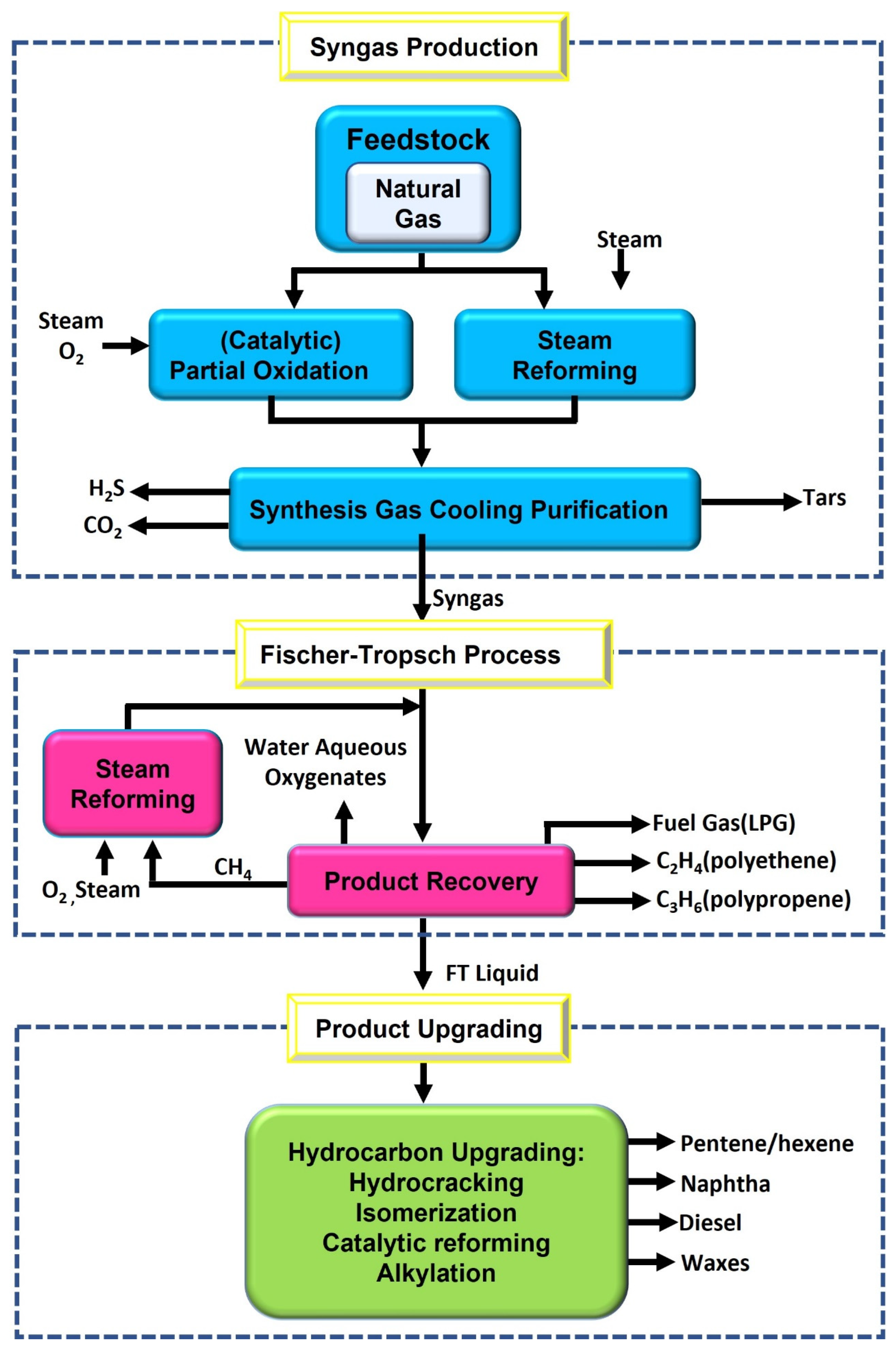
2. GTL Processes Steps

2.1. Synthesis Gas Production

Syngas can be produced by NG reforming technologies [13,14,15,16,17,18]. The feedstock would react with oxygen or steam to produce a mixture of hydrogen, carbon monoxide, and carbon dioxide. Syngas can be produced by several technologies, such as steam methane reforming that produces a mixture of a high hydrogen-to-carbon monoxide ratio. This can be higher than required, where this technology can be operated without the use of oxygen in the feedstock mixture and it does not require high temperature. Another option is the partial oxidation process (POX). The use of POX is accompanied by the use of oxygen and high temperature, which may result in the formation of soot. In addition, there is the autothermal reforming (ATR) process, where endothermic syngas reforming reactions are carried out automatically due to the internal heat generated by the oxidation of a percentage of the feed. The hydrogen-to-carbon monoxide ratio of this process is the most favorable when using cobalt-based catalysts. This process requires oxygen. Heat exchange for reforming allows for flexible application and the use of small equipment, but some cases require combining it with other syngas production methods to complete the job. Many commercial processes rely on the ATR when processing in high capacities [6,19,20].
Production of higher-value fuels and chemicals using syngas through NG indirect conversion has higher efficiency than the direct conversion methods; thus, it is still industrially much preferred [21,22,23]. Syngas is mainly produced by the POX process, steam reforming (SMR) process, or their combination (e.g., ATR) [7,23]. Figure 2 represents natural gas’s direct and indirect conversion into higher-value chemicals. Syngas has become the industrially favored method for the indirect conversion of natural gas into higher-value chemicals and fuels because it is more efficient than the direct conversion methods that are currently available [24].
Syngas is an important organic synthesis intermediate. It provides pure H2 and CO needed for the conversion in the FT process; the H2 and CO are obtained from NG (methane molecule) and reconfigured by different technologies.
All current technologies for NG conversion into syngas are made from SMR (Reaction (1)) and POX (Reaction (2)) [25,26,27]. Carbon dioxide reforming of methane (CDR; Reaction (3)), has yet to be carried out commercially due to the lack of catalysts for such reaction [28].
Steam   reforming                   C H 4 + H 2 O   C O + 3 H 2
Partial   oxidation                     C H 4 + 1 2 O 2 C O + 2 H 2
CO 2 reforming                     C H 4 + C O 2 2 C O + 2 H 2
Reactions (1) and (3) occur on supported catalysts. Mainly, nickel-containing catalysts are used for carbon dioxide or steam reforming at temperatures of 700–900 °C using large amounts of heat [25,26,27,28]. Water gas shift reaction (Reaction (4)) is accompanied by an inevitable partial loss of CO gas [28]:
Water   gas   shift   reaction : C O + H 2 O C O 2 + H 2
On the other hand, the POX process (Reaction (2)) is exothermic; thus, it requires a high operating temperature and no catalyst for syngas production at a 1.7–1.8:1 carbon oxide-to-hydrogen (CO:H2) ratio. This process can exhibit a carbon loss as it turns into soot due to the high operating temperature [26]. A CO:H2 ratio of about 1:2 and a lower temperature can be achieved by catalytic oxidation. The reaction mixture will be close to equilibrium at high methane conversion [28]. This process uses pure oxygen that is produced using low-temperature separation vessels; therefore, it has a high cost because pure oxygen production comprises about 40% of the total syngas plant cost [24]. Other methods for producing pure oxygen at lower costs, such as using membrane technology, are still in the research stage [26,28].
In oxidation processes, air may replace pure oxygen, but in such cases, the overall cost of the process will be higher because it requires heating large amounts of unwanted nitrogen. In addition, such types of processes can only be feasible under the availability of a local cheap gas source [28,29,30,31]. The ratio of CO:H2 in syngas varies, according to the process used to produce it, from 1:3 for SMR to 1:1 for CDR. Different processes prefer different specific quantitative compositions of syngas. For example, ammonia production, where a maximum production of hydrogen is desirable, needs a 1:1 CO:H2 ratio; methanol synthesis needs a 1:2 CO:H2 ratio; and hydrocarbon synthesis needs a CO:H2 ratio equal or more than 1:1.5 [28]. Syngas composition can be upgraded based on the industry needs by water gas shift reaction, gas separation, or by the addition of hydrogen from other available sources. In the 1930s, the standard oil of New Jersey was the first to commercialize the use of syngas [28]. This technology is still responsible for producing about 95% of the net global syngas production despite the development of other technologies [32,33].
Removal of syngas from the POX process oven and the heating cost for syngas production are the most crucial technical problems encountered in the industry [34,35]. The autothermal process mentioned previously was found to be a reasonable solution to heat transfer problems associated with the SMR process, where Reaction (3) would provide enough energy along with the energy acquired by the combustion of a portion of methane to assist Reaction (1). In addition, reduced soot formation and oxygen consumption will be achieved compared to the POX process [36]. Haldor Topsøe is the leading force in autothermal-based GTL plants in Nigeria, Saudia Arabia Railways (SAR), and Qatar [28]. On the other hand, the catalysts used in the ATR process can sometimes suffer from alumina depositions on the catalysts particles leading to an increased pressure drop along the bed due to a reduced void space. This could lead to hot spots on the reactor shell due to bypassing reaction gases into the refractory lining [7]. Due to the high temperatures in the combustion chamber, alumina from the refractory material evaporates and interacts with the catalyst. The endothermic reforming process keeps the catalyst quite cold, which provides favorable conditions for alumina vapor deposition [7]. Shell has updated their still bottom POX processes by reorienting them to NG for its GTL facilities in Bintulu (Malaysia) and Pearl (Qatar). The reaction temperature ranges from 1300 to 1500 °C, the pressure may reach 7 MPa, the O:H2 ratio at the oven output is 1.7 to 1.8, the H2 content is 2%, and the methane losses are 0.5% [28]. Besides that, the required 2.1:1 H2:CO ratio could be maintained by small syngas plant based on the SMR process [28,37]. A GTL plant’s estimated capital investment can be 40–70% of the total cost [28,37]. In addition, high risks are also associated with pure oxygen production. Table 1 presents the composition of syngas produced using different technology [38,39,40].
Syngas production costs can be further reduced by producing syngas at a reduced steam/carbon ratio [38]. Basini and Piovesan [38] have concluded that a combined SMR and ATR reforming process has the lowest possible investment and production costs at an H2:CO ratio of 2.
Great interest was given to developing more economically feasible alternative technologies for syngas production, because this step only takes up to 60–70% of a GTL project’s overall capital cost [41,42]. One of those technologies is the catalytic partial oxidation of methane (CPO; Reaction (2)) [3,43].
Despite all the advancements in catalyst development of CPO, several problems still need to be resolved before CPO technology can be commercially used. One disadvantage of this technique is that the mixture is very combustible and may burn at temperatures exceeding 250 °C. Therefore, the reactants mixture might not be pre-heated at high temperature, leading to a high natural gas and oxygen consumption, since part of the feed must be burned to produce the heat necessary to reach the reaction temperature [3,44].
The CPO is yet to compete with the ATR process because the air separation unit (ASU) takes up to 40% of the GTL plant capital cost. This problem can be eliminated by using a ceramic membrane reactor (Figure 3) where partial oxidation and air separation occur at the same equipment, thus eliminating the cost of the oxygen plant and enhancing the economic feasibility of the process [26,41]. This technology depends on a dense ceramic membrane that provides oxygen ionic and electronic conductivity at elevated temperatures, approximately 800–900 °C [3,45].
Oxygen production by membrane separation technology has encountered several critical problems throughout the past years, and improvements are still required. Several crucial factors, such as module design, sealing, and membrane geometry, must be taken into account to enhance the performance of the membranes [46,47,48].
The development of compact reformers can significantly reduce syngas production costs. An example is the plate-type reformer, where the endothermic reaction is provided with energy through indirect heat transfer by the exothermic reaction [49,50].
The reformer plates are arranged in a stack. Each plate has a side where catalytic combustion takes place and provides heat to the steam reforming reaction that occurs on the other side, which is coated with the required catalyst [3]. Plate reformers have several advantages, including: (i) Its reduced weight and size as compared to conventional fired tubular reformers [50], it can be used for associated gas conversion into liquid fuels, especially in remote locations and offshore platforms because it is compact; (ii) it requires a lower capital cost due to its standardized design; (iii) it can be a solution to mass and heat transfer problems encountered in conventional reformers because of its design that enables a better mass and heat transfer resulting in an improved thermal efficiency; (iv) its faster startup because the thermal inertia of each plate is smaller; (v) it is a flexible technology due to its modular nature, where additional units can be used in case of a scale-up requirement; (vi) not requiring oxygen; and (vii) its lower construction costs and NOx emissions due to replacing homogeneous combustion with catalytic combustion where the latter proceeds at lower temperatures [3].
For small-scale FTS facilities, a new class of highly productive small-scale reactors has just been introduced. Microchannel reactors are an excellent option for addressing the issues imposed by the small-scale technique due to their compact size and adaptability. It is feasible to get high one-pass conversions by utilizing optimized catalysts because microchannel reactors have a high capacity to handle the enormous heat created during the FTS reaction and synthesis gas production. Velocys’ commercialization of these reactors is reported to improve catalyst productivity compared to conventional slurry-bed and fixed-bed reactors by a factor of 5 to 10 [48]. A modern opinion suggests that industrial processes can be established with improved sustainability by utilizing carbon dioxide produced as the main product of power plants’ total combustion of NG, coal, renewable resources, or as a byproduct of the chemical industry. Such a step forward can be achieved by the dry reforming of methane processes (DRM) which is basically a CO2 reduction process by a hydrogen-rich molecule or a methane oxidation step by CO2. The DRM processes can be used to utilize CO2 for conversion into more valuable chemical intermediates [23,51]. On a large-scale basis, using the reduction equivalents for CO2 conversion in high-temperature processes is yet to be achieved as such types of processes can hardly be competitive with the state-of-the-art POX, ATR, and SMR processes. In addition, those processes are yet to achieve an appreciable improvement in CO2 footprint [23].

2.2. Fischer–Tropsch Synthesis and Technologies

Fischer–Tropsch (FT) synthesis was originally invented in the 1920s by Franz Fischer and Hans Tropsch while working at the Kaiser Wilhelm Institute and is considered the most essential step in the GTL process [3,52,53].
The FT process can be used to catalytically convert syngas into products that can be upgraded into lubricants, synthetic fuels, petrochemicals, and most importantly, low aromatics sulfur-free diesel fuel, jet fuel, and gasoline [54,55]. Another advantage of this process is the ability to adjust the H2:CO of the upstream gasification and reforming processes [56,57]. The FT process can produce various hydrocarbons by several reactions, yet, the overall reaction may be stated and summarized as in Table 2.
Therefore, the FT synthesis can be described as a CO hydro-polymerization process, where a wide range of hydrocarbons are formed [59,60,61,62] through a series of events starting with CO adsorption on the catalyst surface, then CO dissociation causing the chain initiation, followed by the hydrogenation. Two types of reactions take place on the catalyst surface: chain propagation, where a monomer is added to the intermediate that was already produced, and product formation by chain termination [59].
Transition metals such as ruthenium, cobalt, and iron are traditionally used for FT synthesis. Catalyzation nickel is not used as a commercial catalyst in this process because nickel favors methane formation [3,63].
Syngas composition is highly affected by the catalyst used for the reaction. FT synthesis selectivity is also affected by pressure, where high pressure supports high conversions and the formation of long-chained alkanes. Besides that, the great technological knowledge attained after the Fischer–Tropsch process has been around for a very long time, but FT catalysts face numerous challenges [3] namely, stable catalysts for high-pressure operation, as well as metal particle size control.
In a GTL process, the FT step can either be achieved at high temperature (HTFT) or at low temperature (LTFT). The LTFT process can either be achieved using a multi-tubular fixed bed reactor (e.g., Shell) or a slurry-phase bubble column reactor (e.g., Sasol). In both cases, a cobalt-based catalyst is used to catalyze the reaction at low temperature producing sulfur and aromatics-free syncrude with a large fraction of waxy, heavy hydrocarbon. The LTFT process can be operated with a conversion of about 60% at 2–2.5 MPa and 220–240 °C; in this case, the problem of catalyst activation can be limited by using more than one reactor in series or by recycling [64,65,66].
On the other hand, the HTFT process can be used to produce olefins and light Syncrude. The HTFT process can be carried out commercially using several arrangements of reactors such as the circulating bed, bubble column/slurry phase, multitube fixed bed, and fluidized bed reactors. Waxy paraffinic products can be produced from three-phase gas-liquid-solid trickle fixed bed reactors operating at 10–25 bar and 180–250 °C [67]. Such reactors are used in the Shell middle distillate synthesis (SMDS) process and in the ARGE process by Sasol. Bubble column or slurry phase reactors where the catalyst is dispersed in the process-derived wax are used in the Sasol slurry phase distillate (SSPD) processes [68]. Two-phase gas-solid fluidized bed reactors are used where lighter olefins and gasoline production is required. Sasol’s advanced synthol (SAS) reactor has several advantages: ease of operation, simplicity, low operating cost, high capacity, thermal efficiency, and high conversion at high gas load. There is an agreement that the process can be operated with the best compromise between cost and performance by using cobalt-based catalysts [66,69].
Since the discovery of cobalt catalysts in the 1930s, where asbestos-supported cobalt oxide was synthesized, cobalt catalysts have advanced to a highly optimized silica, titania, and modified alumina-supported catalysts with high activity and were promoted with basic oxides and noble metals. In the 1950s, iron-based catalysts drew the attention of researchers, and studies on such catalysts achieved an important advancement in catalyst design, promoters, and supports by the end of the 1970s [66,70].

3. Catalysts of FTS

Under FT-synthesis reaction conditions, only catalysts based on transition metals such as Fe, Co, Ni, and Ru have the activity toward both metal carbonyl formation reaction and the hydrogenation reaction under FT reaction conditions [71,72].
Numerous studies have demonstrated how several variables influence an FT catalyst’s catalytic behavior. As listed in Table 3, several catalyst aspects can considerably impact the activity and product selectivity in addition to technical considerations such as reactor design and operating conditions [31,73,74,75].
Commercially, only iron- and cobalt-based catalysts are used for hydrocarbon synthesis, where cobalt is more active than iron [76,77,78]. Despite the high activity and selectivity of ruthenium (Ru), high methane will be produced by the process when this catalyst is used at low pressures. In contrast, high molecular paraffins will be produced at high pressures and low temperatures without using any promoters [47]. Still, due to their high price and scarcity, Ru-based catalysts are not for commercial use [28,79].
A couple of major problems limited nickel-based catalyst applications in FT technology despite its high activity. The first problem was the metal loss during operation due to volatile carbonyl formation. The second problem was the low yield of long-chained hydrocarbons caused by methanation since nickel-based catalysts are highly active for such reactions [61,80,81,82,83]. Table 4 compares the four metals and their four characteristics.
The main characteristic of FT catalysts based on cobalt is the high activity toward the FT reaction while having almost zero activity toward the water gas shift reaction; thus, reaction operating conditions are predetermined based on those characteristics [84]. Iso-alkanes, α-olefins, and linear alkanes can also be produced using cobalt-based catalysts under low temperatures (180–240 °C). In contrast, more methane will be produced by carbon monoxide hydrogenation when the catalysts are used at higher temperatures, and such cases are not acceptable in FT synthesis. Under the same conditions, heavier products will be produced when cobalt-based catalysts are used as compared to iron-based catalysts [73]. The opposite outcomes, however, were also observed and reported in the literature [67,85]. When cobalt-based catalysts are used in the FT process, cobalt is more productive under greater per pass conversion regimes because cobalt catalysts are more effective at lower space velocities (higher water partial pressures). Besides that, the iron catalyst performs better at greater operating pressures and space velocities [70].
A wider range of operating temperatures of up to 320–350 °C can be used to produce light products with a chain growth probability of 0.67–0.68 can be achieved by using iron-based catalysts [86,87]. Thus, the selectivity toward methanation is still not that high, even at temperatures of about 340 °C [28].
Iron-based catalysts are active toward Reaction (4); thus, carboxylic acids, aldehydes, alcohols, and ketones are also produced due to the partial inefficient consumption of carbon monoxide. However, there is an increase in the overall production of hydrogen due to Reaction (4). This makes iron catalysts more preferably used than cobalt-based catalysts with H2-poor syngas as obtained from the gasification of biomass or coal [28].
Water formation affects the reaction kinetics when the catalyst is iron-based but not when the catalyst is cobalt-based [87,88]. At the exact operating conditions, the increase in the water partial pressure at high conversions will slow the reaction rate causing a lower CO conversion over one run when an iron-based catalyst is used compared to the case where cobalt is used instead. Despite the lower price of iron-based catalysts, cobalt catalysts are more popular due to their higher stability. Iron catalysts have lower durability at low temperatures, and sulfur compounds can poison them. In addition, iron catalysts suffer from coke formation at fast rates when used at high temperatures, and replacement of process catalyst is required. Moreover, carbon dioxide and water can oxidize iron-based catalysts, and thus, their activity is affected [77,87].
The activity of cobalt-based catalysts can be defined by the micromoles of CO or H2 adsorbed on the catalyst surface (cobalt atoms), whereas such a definition does not apply to iron-based catalysts. This different behavior of catalyst activity is because these iron-based catalysts are active for both the FTS reaction and the WGS reaction, especially at higher levels of CO conversion. Additionally, promoters have different effects on the two catalysts discussed. Promoters strongly affect iron-based catalysts’ selectivity and activity, while they do not affect the selectivity of cobalt-based catalysts but decrease their activity [89,90].
Cobalt- and iron-based catalysts are the only suitable options for industrial applications. The two catalysts are mainly different in their active phases during the FT synthesis, which affects the selectivity of the catalyst. While cobalt-based catalysts, in the supported form, are more preferred in industry, GTL plants widely depend on iron-based catalysts in the precipitated form.

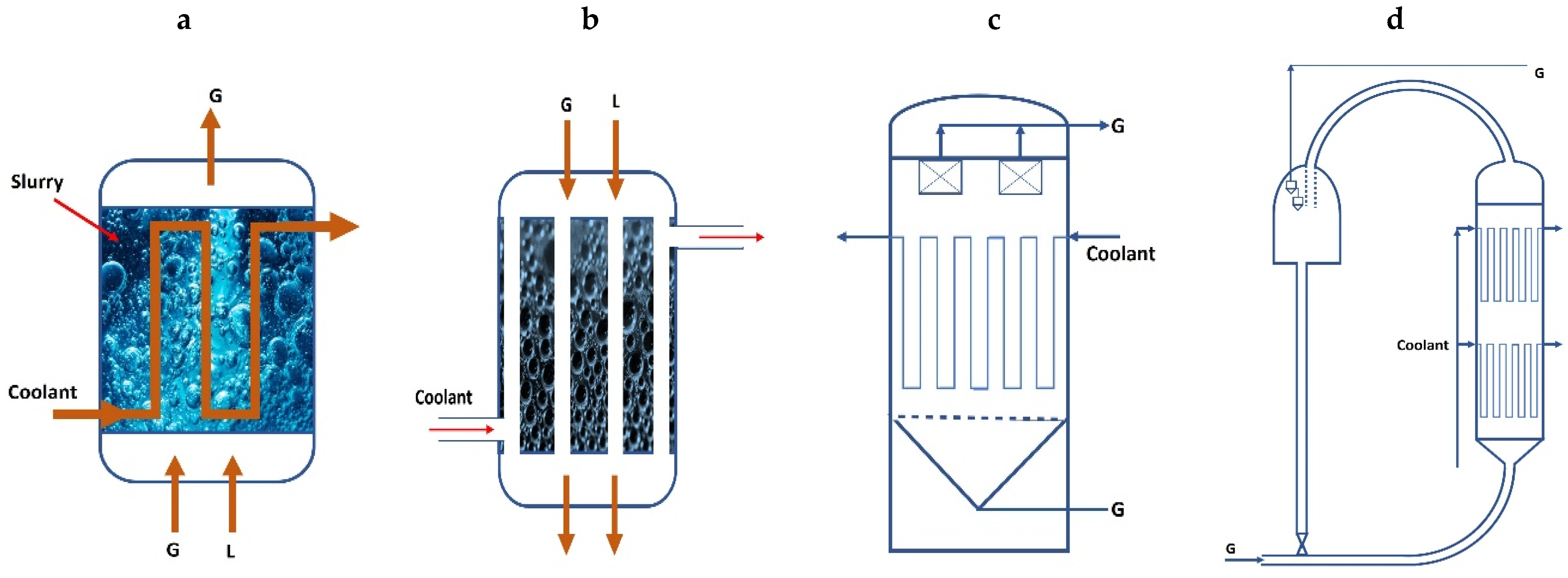
4. Fischer–Tropsch Reactors

The chain growth probability (alpha) in FT synthesis governs product distribution. This parameter is a process variable that depends on the reaction temperature and strongly influences FTS selectivity. This is expected since the activation energy of the growing step is lower than that of the termination step [88,91]. Reactors for FT synthesis are designed to achieve excellent temperature control. This is because FT is highly exothermic, and methane and other light products can be formed when FT is operated at high temperatures. The design avoids catalyst damage due to elevated temperatures [92,93,94]. Different reactors are used in FT synthesis, such as fluidized bed reactors, slurry bubble columns, and fixed bed reactors (Figure 4) [93,95].
Tubular fixed bed and slurry reactors are utilized in LTFT to produce long-chain hydrocarbons using iron- or cobalt-based catalysts [94]. Different reactor designs can be achieved and used based on different technologies. For commercial applications, the following three types are most predominantly used (Figure 4) [92]:
  • Fluidized bed and circulating fluidized bed reactor (Figure 4d,c, respectively): This type of reactor was reported to suffer from reduced catalyst lifetime due to carbon formation caused by high operating temperatures. In addition, such reactors are bulky and complex; thus, scale-up and control of such reactors are difficult. This type of technology can be found in a complex in south Africa by Sasolburg [93,95].
  • Fixed bed tube and the multi-tubular reactor (Figure 4b): The latter is the most favorable type of this arrangement. The mode of operation, in this case, is once through, where medium pressure is used, and tubes containing the catalyst are placed in the shell side of the reactor (cooling medium-mostly water-side). This type of reactor was originally developed in Germany after World War II [92,96]. Multi-tubular fixed-bed reactors have the advantages of simple operation, ease of product separation from the catalysts, and a wider range of operating temperatures. The disadvantages of this arrangement are [94]: i- high capital investment; ii- mechanical difficulties in scale-up; iii- catalysts replacement is not possible during operation; and iv- high gas compression costs due to high-pressure drops (0.3–0.7 MPa).
  • Slurry bubble column (Figure 4a): In this type of reactor, syngas is sparged through a slurry of recycled liquid product and catalyst particles. Scale-up of this type is accompanied by longer piloting times and hydrodynamics changes [92,97]. LTFT processes normally rely on slurry reactors because such processes promote the production of liquid wax that can be used as the suspension medium. Despite the advantage of excellent heat transfer to surrounding liquid medium of this type, the cost and difficulty in separating the catalyst from the reaction medium limit the application of slurry reactors on a commercial basis [92].
Table 5 provides information about commercial FTS reactors, and Figure 4 summarizes the FTS reactors. The main different possibilities of reactor cooling are [92]:
  • Fixed-bed reactors can be cooled internally;
  • Fixed-bed reactors can be cooled by liquid or gas recycle;
  • Staged fixed-bed reactors can be cooled directly by a distributed feed of fresh synthesis gas.
Remarkably, highly exothermic gas–liquid reactions were studied in various reactor types in a relatively short period and under difficult circumstances using feasible and highly performing heterogeneous catalysts despite that reaction engineering and heterogeneous catalyst development were yet to be considered complete at that time.
Figure 4. Possible reactors for Fischer–Tropsch synthesis [93,99]: (a) Slurry bubble column reactor; (b) Multi-tubular trickle bed reactor; (c) circulating fluidized bed reactor; (d) fluidized bed reactor.
Methane 02 00002 g004

5. Separation and Product Improvement

The upgrading step is the last step in a GTL process, which may include hydro-isomerization, hydrotreating, and hydrocracking, which may produce more food-grade wax and high-quality lubricants or maximize the produced naphtha and diesel from paraffinic compounds [3,100]. Gasoline hydrocarbons with olefins content of about 70% will be produced from the HTFT syncrude. These are considered oxygenates-rich hydrocarbons (mainly ketones, carboxylic acids, and alcohols). On the other hand, 50% of the LTFT production will be paraffinic wax [3,28].
Although the aromatic content in the HTFT synthesis gasoline is within acceptable limits, the olefins content is a bit high, and the octane number is considered to be less than the modern requirements [101]. Therefore, several upgrading processes will be required to produce high-quality gasoline. These processes include an isomerization step for the C5–C6 fraction, platforming for the C7–C10, and oligomerization followed by hydrogenation for the C3–C4 olefins [101]. These processes will normally be accompanied by another step where propylene can be converted to the high octane number di-isopropyl ether [28]. All these processes make it economically unfavorable to produce high-quality gasoline using this route [101].
As the carbon number increases, hydrocarbons tend to be more saturated and even though LTFT straight-run naphtha and distillate have a fair content of oxygenated and olefins, the heavier products are mostly n-paraffin waxes [3,102]. Additionally, branched hydrocarbons can also be found in LTFT [3]. As with the straight-run petroleum refining, market demands cannot be matched by straight-run FT product distribution with respect to quality and quantity. Thus, the production of a large fraction of C-C4 gases, particularly in HTFT, and a heavy residue of high molecular weight n-alkanes will always be produced simultaneously with the production of diesel, kerosene, and naphtha, mainly in LTFT [3].
Using bifunctional metal–zeolite catalysts can increase the gasoline fraction’s aromatics and/or paraffin content. C1–C10 hydrocarbons containing iso-paraffins of about 80% content can be selectively synthesized by systems of cobalt–zeolite catalyst. Synthetic paraffins C11–C20 have a cetane number of around 70–80 [101] and are linearly structured [28].
The nil sulfur and nitrogen contents in FTS naphtha did not make the process attractive enough because the octane number of the produced naphtha was highly affected by the absence of the aromatics and linearity of hydrocarbons. Particulate emission and high cetane numbers highly favor the same characteristics in the case of FT diesel. A diesel fraction with a cetane number of about 7 can be obtained using an LTFT synthesis with a cobalt-based catalyst. In contrast, a diesel fraction with a cetane number of 50 can be obtained by HTFT followed by hydrogenation of olefins where the CN range acceptable by the market is 45–50 [97]. The environmental impact of the fuel can be significantly reduced by eliminating naphthenes, aromatics, and heteroatoms. On the other hand, these characteristics negatively affect the density, lubricity, and cold flow properties of straight-run FT diesel [3,97]. Regulations and limitations can be met by mixing aromatics and sulfur-free FT products with traditional fuels [103].
Besides fuels, a combination of upgrading processes can follow the FTS to produce different products such as ethene, propene, ketones, solvents, alcohols, specialty waxes, α-olefins, and others. The added value of the FT byproducts greatly affects the process economy, making it more economically attractive. Yet, FTS products are upgraded by blending them with transportation fuels because of the latter’s better characteristics (Table 6).

6. Fischer–Tropsch Industrial Processes

In 1913, Baden Aniline and Soda Factory (BASF) patented a process where carbon methoxide was hydrogenated into hydrocarbons other than ketones, methane, alcohols, and acids. However, these efforts were not continued by BASF due to the high requirement of methanol and ammonia production because of World War I [60,106]. In 1923, Fischer and Tropsch in Germany indicated that an oily product could be obtained from syngas at 100–150 atm and 325–425 °C when using an alkali-iron catalyst. The product was called synthol and was mainly comprised of aldehydes, alcohols, ketones, acids, esters, and other hydrocarbons. Additionally, a low yield of an almost completely paraffinic product was found to be obtained at lower pressure (about 7 atm) containing a small amount of oxygenated organic compounds [60,107]. In 1925, oxygenated compounds were eliminated using cobalt–iron catalyst at 250–300 °C and 1 atm, obtaining a product with only gas hydrocarbons and liquids. Due to its high activity, low/medium pressure (1–15 atm), and low reaction temperature (180–200 °C), the development of cobalt-based catalyst from 1933 to 1938 became the standard FT catalyst [11]. In 1936, Steinkohlen–Bergwerk Rheinpreussen established the first commercial-size plant for FTS, in Ruhr, Germany, to produce primary oils (diesel oil and gasoline) and paraffin wax. Several FT plants produced primary oils at atmospheric and medium pressure, 180–200 °C, with the standard FT catalyst; these plants were constructed and operated in Germany [60].
The construction of FT plants was stopped by the start of World War II (1939–1945). However, development toward cheaper catalysts persisted. Iron-based catalysts were the most favorable over the cobalt-based type due to the high price of cobalt and its limited supply in that period. After the war, and especially in the latter months of the war, German syn-fuel scientists and their technical reports were investigated by the British Intelligence Objectives Subcommittee (BIOS) and the United States Technical Oil Mission (TOM) [60]. Table 7 Summarizes the major companies active in Fischer–Tropsch [108].

7. Conclusions

The well-known FTS-based GTL technologies have faced ups and downs throughout the years. However, as environmental regulations have become more stringent, the shift toward such technologies has become more interesting as the industry has shifted toward producing cleaner fuels and diesel of high cetane numbers. The GTL technologies comprise three main steps: the generation of syngas, the FTS, and the last step, where upgrading takes place, is basically hydro-isomerization and hydrocracking. The GTL technology still faces several challenges in all the mentioned steps in terms of the catalysis despite of all the research and development in the technology. In terms of syngas generation, the SMR, ATR, and POX are the most chosen paths. The biggest challenge in the syngas generation step is related to obtaining the right H2:CO ratio for the GTL using a low steam-to-carbon ratio and without the side effect of carbon formation. Previous studies established a great understanding of the carbon formation mechanism; thus, little has been made concerning developing newer catalysts. In a GTL plant, 60–70% of the total capital is allocated to the syngas production step; thus, more attention should be given to this step, particularly the development of the catalytic partial oxidation process CPO.
Modern CPO processes are based on a ceramic membrane reactor where both partial oxidation and air separation take place, giving the advantage of eliminating the oxygen plant and thus reducing the total capital cost of the plant. Improving the mechanical, thermal, and chemical stability of the membrane materials by keeping high electronic and ionic conductivities can achieve the commercialization of such a process. Attention to catalytic challenges accompanying the FTS is a must, especially when it comes to enhancement in the selectivity to produce high-octane gasoline, lowering the production cost, new reactor systems, and enhanced selectivity toward the production of high molecular weight hydrocarbons. Modern industrial FTS units rely on cobalt-based catalysts, and this type’s traditional form comes with rather low cobalt dispersion.
Slurry bubble column reactors and internal water-cooling fixed bed reactors are the most used systems commercially. The fixed bed reactor system is used in all Shell projects and plants due to its robust design and the simplicity of its scale-up procedure. Sasol projects are based on the bubble column reactor due to its advantageous heat removal and catalytic effectiveness, allowing for a higher space-time yield due to a higher average temperature in the reactor. Additionally, this system shows higher production capacities at relatively lower costs compared to the multi-tubular reactor system. The main disadvantages of this system are the mathematical models for scaling up and design and the necessity for suspended catalyst separation. These issues can be further improved in the future.
Again, the use of microreactors for the FTS in a GTL process offers several advantages, such as excellent temperature control and control of the degree of polymerization (alpha). Furthermore, because the facility would be established on an FPSO, such technology would allow for the exploitation of offshore gas resources. Catalytically, more attention should be given to the generation of a convenient catalyst layer and the coating process for a given configuration. The upgrading step of a GTL process aims to either maximize naphtha and diesel production from paraffinic hydrocarbons or generate high-quality food-grade wax and lubricants.

Author Contributions

Conceptualization, F.T.A. and T.M.A.; methodology, Z.M.S. and H.S.M.; validation, F.T.A., H.S.M. and N.S.A.; resources, A.N.S. and N.M.C.S.; writing—original draft preparation, N.M.C.S. and A.N.S.; writing review and editing, A.N.S., F.T.A. and N.M.C.S.; visualization, T.M.A., H.G.S. and N.M.C.S.; supervision, N.S.A.; project administration, H.S.M. All authors have read and agreed to the published version of the manuscript.

Funding

This research received no external funding.

Data Availability Statement

All relevant data are included in the paper.

Acknowledgments

The authors are grateful to the Department of Chemical Engineering at the University of Technology-Iraq, the Mustansiriyah University/College of Engineering/Materials Engineering Department Baghdad-Iraq, the Department of Chemical and Petroleum Industries Engineering, Al-Mustaqbal University College, Babylon, Iraq, and the Department of Civil Engineering, and the Memorial University of Newfoundland, St. John’s, NL A1B 3X5, Canada.

Conflicts of Interest

We certify that the authors have no affiliations with or involvement in any organization or entity with any financial interest or nonfinancial interest in the subject matter or materials discussed in this manuscript.

Nomenclature

ASUAir separation unit
ATRAutothermal reforming
BASFBaden Aniline and Soda Factory
BIOSBritish Intelligence Objectives Subcommittee
CO2Carbon dioxide
CDRCarbon dioxide reforming of methane
CH4Methane
CNCetane number
COCarbon monoxide
CPOCatalytic partial oxidation of methane
DRMDry reforming of methane processes
FTFischer–Tropsch
FTSFischer–Tropsch synthesis
GTLGas-to-liquid technology
H2Hydrogen
HTFTHigh temperature Fischer–Tropsch
LNGLiquefied natural gas
LPGLiquefied Petroleum Gas
LTFTLow temperature Fischer–Tropsch
NGNatural gas
POXPartial oxidation process
SASSasol’s advanced Synthol
SMDSShell middle distillate synthesis
SMRSteam reforming
SRSteam reforming
SSPDSasol slurry phase distillate
WGSWater gas shift reaction

References

  1. Ryi, S.-K.; Lee, S.-W.; Park, J.-W.; Oh, D.-K.; Park, J.-S.; Kim, S.S. Combined steam and CO2 reforming of methane using catalytic nickel membrane for gas to liquid (GTL) process. Catal. Today 2014, 236, 49–56. [Google Scholar] [CrossRef]
  2. Wood, D.A.; Nwaoha, C.; Towler, B.F. Gas-to-liquids (GTL): A review of an industry offering several routes for monetizing natural gas. J. Nat. Gas Sci. Eng. 2012, 9, 196–208. [Google Scholar] [CrossRef]
  3. Sousa-Aguiar, E.F.; Noronha, F.B.; Faro, J.A. The main catalytic challenges in GTL (gas-to-liquids) processes. Catal. Sci. Technol. 2011, 1, 698–713. [Google Scholar] [CrossRef]
  4. Kumar, J.C.R.; Majid, M.A. Renewable energy for sustainable development in India: Current status, future prospects, challenges, employment, and investment opportunities. Energy Sustain. Soc. 2020, 10, 2. [Google Scholar] [CrossRef]
  5. Sorrell, S. Reducing energy demand: A review of issues, challenges and approaches. Renew. Sustain. Energy Rev. 2015, 47, 74–82. [Google Scholar] [CrossRef] [Green Version]
  6. Bao, B.; El-Halwagi, M.M.; Elbashir, N.O. Simulation, integration, and economic analysis of gas-to-liquid processes. Fuel Process. Technol. 2010, 91, 703–713. [Google Scholar] [CrossRef] [Green Version]
  7. Dybkjær, I.; Aasberg-Petersen, K. Synthesis gas technology large-scale applications. Can. J. Chem. Eng. 2016, 94, 607–612. [Google Scholar] [CrossRef]
  8. Goellner, J.F.; Shah, V.; Turner, M.J.; Kuehn, N.J.; Littlefield, G.C.; Marriott, J. Analysis of Natural Gas-to Liquid Transportation Fuels via Fischer-Tropsch, Report DOE/NETL-2013/1597; United States Department of Energy (DOE), National Energy Technology Laboratory (NETL): Pittsburgh, PA, USA, 2013.
  9. Zhang, Y.; Sahir, A.H.; Tan, E.C.D.; Talmadge, M.S.; Davis, R.; Biddy, M.J.; Tao, L. Economic and environmental potentials for natural gas to enhance biomass-to-liquid fuels technologies. Green Chem. 2018, 20, 5358–5373. [Google Scholar] [CrossRef] [Green Version]
  10. Elbashir, N.O.; Eljack, F.T. A Method to Design an Advanced Gas-to-Liquid Technology Reactor for Fischer-Tropsch Synthesis. In Proceedings of the 2nd Annual Gas Processing Symposium, Doha, Qatar, 11–14 January 2010; Benyahia, F., Eljack, F.T., Eds.; Elsevier: Amsterdam, The Netherlands, 2010; Volume 2, pp. 369–377. [Google Scholar]
  11. Lee, H.-J.; Choi, J.-H.; Garforth, A.; Hwang, S. Conceptual Design of a Fischer–Tropsch Reactor in a Gas-to-Liquid Process. Ind. Eng. Chem. Res. 2015, 54, 6749–6760. [Google Scholar] [CrossRef]
  12. Lee, H.-J. Optimization of Fischer-Tropsch Plant; The University of Manchester (United Kingdom): Manchester, UK, 2011. [Google Scholar]
  13. Wilhelm, D.; Simbeck, D.; Karp, A.; Dickenson, R. Syngas production for gas-to-liquids applications: Technologies, issues and outlook. Fuel Process. Technol. 2001, 71, 139–148. [Google Scholar] [CrossRef]
  14. Suehiro, Y.; Ihara, M.; Katakura, K.; Nakamura, A.; Sakamoto, A.; Kawazuishi, K.; Kajiyama, R.; Fujimoto, K.; Ohnishi, Y.; Okado, H.; et al. New GTL Process—Best Candidate for Reduction of CO2 in Natural Gas Utilization. In Proceedings of the SPE Asia Pacific Oil and Gas Conference and Exhibition, Perth, Australia, 18–20 October 2004. [Google Scholar]
  15. Ntuk, U.U.; Bassey, E.N.; Etuk, B.R. A novel syngas production process design for gas-to-liquid (gtl) technology. J. Niger. Soc. Chem. Eng. 2012, 27, 1–8. [Google Scholar]
  16. Nourbakhsh, H.; Khani, Y.; Zamaniyan, A.; Bahadoran, F. Hydrogen and syngas production through dynamic chemical looping reforming-decomposition of methane. Int. J. Hydrog. Energy 2022, 47, 9835–9852. [Google Scholar] [CrossRef]
  17. Rezaei, E.; Dzuryk, S. Techno-economic comparison of reverse water gas shift reaction to steam and dry methane reforming reactions for syngas production. Chem. Eng. Res. Des. 2019, 144, 354–369. [Google Scholar] [CrossRef]
  18. Tso, W.W.; Niziolek, A.M.; Onel, O.; Demirhan, C.D.; Floudas, C.A.; Pistikopoulos, E.N. Enhancing natural gas-to-liquids (GTL) processes through chemical looping for syngas production: Process synthesis and global optimization. Comput. Chem. Eng. 2018, 113, 222–239. [Google Scholar] [CrossRef]
  19. Iandoli, C.L.; Kjelstrup, S. Exergy Analysis of a GTL Process Based on Low-Temperature Slurry F−T Reactor Technology with a Cobalt Catalyst. Energy Fuels 2007, 21, 2317–2324. [Google Scholar] [CrossRef]
  20. Yagi, F.; Kanai, R.; Wakamatsu, S.; Kajiyama, R.; Suehiro, Y.; Shimura, M. Development of synthesis gas production catalyst and process. Catal. Today 2005, 104, 2–6. [Google Scholar] [CrossRef]
  21. Rostrup-Nielsen, J. 40 years in catalysis. Catal. Today 2006, 111, 4–11. [Google Scholar]
  22. Romm, J.J. The Hype about Hydrogen: Fact and Fiction in the Race to Save the Climate; Island Press: Washington, DC, USA, 2004. [Google Scholar]
  23. Schwab, E.; Milanov, A.; Schunk, S.A.; Behrens, A.; Schödel, N. Dry reforming and reverse water gas shift: Alternatives for syngas production? Chem. Ing. Tech. 2015, 87, 347–353. [Google Scholar] [CrossRef]
  24. Thyssen, V.V.; Vilela, V.B.; de Florio, D.Z.; Ferlauto, A.S.; Fonseca, F.C. Direct Conversion of Methane to C2 Hydrocarbons in Solid-State Membrane Reactors at High Temperatures. Chem. Rev. 2022, 122, 3966–3995. [Google Scholar] [CrossRef]
  25. Aouad, S.; Labaki, M.; Ojala, S.; Seelam, P.K.; Turpeinen, E.; Gennequin, C.; Estephane, J.; Abi-Aad, E. A Review on the Dry Reforming Processes for Hydrogen Production: Catalytic Materials and Technologies. Catal. Mater. Hydrog. Prod. Electro Oxid. React. Front. Ceram. Sci 2018, 2, 60–128. [Google Scholar] [CrossRef]
  26. Rostrup-Nielsen, J.R.; Sehested, J.; Nørskov, J.K. Hydrogen and synthesis gas by steam- and CO2 reforming. In Advances in Catalysis; Academic Press: Cambridge, MA, USA, 2002; Volume 47, pp. 65–139. [Google Scholar]
  27. Fakeeha, A.; Ibrahim, A.A.; Aljuraywi, H.; Alqahtani, Y.; Alkhodair, A.; Alswaidan, S.; Abasaeed, A.E.; Kasim, S.O.; Mahmud, S.; Al-Fatesh, A.S. Hydrogen Production by Partial Oxidation Reforming of Methane over Ni Catalysts Supported on High and Low Surface Area Alumina and Zirconia. Processes 2020, 8, 499. [Google Scholar] [CrossRef]
  28. Eliseev, O.L. Gas-to-liquid technologies. Russ. J. Gen. Chem. 2009, 79, 2509–2519. [Google Scholar] [CrossRef]
  29. Osman, A.I.; Mehta, N.; Elgarahy, A.M.; Hefny, M.; Al-Hinai, A.; Al-Muhtaseb, A.a.H.; Rooney, D.W. Hydrogen production, storage, utilisation and environmental impacts: A review. Environ. Chem. Lett. 2022, 20, 153–188. [Google Scholar] [CrossRef]
  30. Jess, A.; Popp, R.; Hedden, K. Fischer–Tropsch-synthesis with nitrogen-rich syngas: Fundamentals and reactor design aspects. Appl. Catal. A Gen. 1999, 186, 321–342. [Google Scholar] [CrossRef]
  31. Van Steen, E.; Claeys, M. Fischer-Tropsch catalysts for the biomass-to-liquid (BTL)-process. Chem. Eng. Technol. Ind. Chem. -Plant Equip. -Process Eng. -Biotechnol. 2008, 31, 655–666. [Google Scholar] [CrossRef]
  32. Onoriode, P.A.; Faruk Ibrahim, Y.; Baba, Y.J. Sustainability Effect of Water Gas Shift Reaction (Syngas) in Catalytic Upgrading of Heavy Crude Oil and Bitumen. In Sustainable Alternative Syngas Fuel; Chaouki, G., Abrar, I., Eds.; IntechOpen: Rijeka, Croatia, 2019; Chapter 3. [Google Scholar]
  33. Arutyunov, V.; Krylov, O. Oxidative Methane Reforming. Usp. Khim. 2005, 74, 1216. [Google Scholar] [CrossRef]
  34. Chen, W.-H. CO2 conversion for syngas production in methane catalytic partial oxidation. J. CO2 Util. 2014, 5, 1–9. [Google Scholar] [CrossRef]
  35. Roseno, K.; Brito Alves, R.; Giudici, R.; Schmal, M. Syngas Production Using Natural Gas from the Environmental Point of View. In Biofuels-State of Development; IntechOpen: London, UK, 2018. [Google Scholar] [CrossRef]
  36. Christensen, T.; Primdahl, I. Improve syngas production using autothermal reforming. Hydrocarb. Process. 1994, 73. [Google Scholar]
  37. Eilers, J.; Posthuma, S.A.; Sie, S.T. The shell middle distillate synthesis process (SMDS). Catal. Lett. 1990, 7, 253–269. [Google Scholar] [CrossRef]
  38. Basini, L.; Piovesan, L. Reduction on synthesis gas costs by decrease of steam/carbon and oxygen/carbon ratios in the feedstock. Ind. Eng. Chem. Res. 1998, 37, 258–266. [Google Scholar] [CrossRef]
  39. Perry, R.H.; Green, D.W.; Maloney, J.O. Perry’s Chemical Engineers’ Handbook; McGraw-Hill Education: New York, NY, USA, 2007. [Google Scholar]
  40. Cybulski, A.; Edvinsson, R.K.; Irandoust, S.; Andersson, B.A.B. Liquid-phase methanol synthesis: Modelling of a monolithic reactor. Chem. Eng. Sci. 1993, 48, 3463–3478. [Google Scholar] [CrossRef]
  41. Wilhelm, D.J. Fuel processing technology. Fuel Process. Technol. 2001, 71, 139. [Google Scholar] [CrossRef]
  42. Basini, L. Catalysis today. Catal. Today 2005, 106, 34. [Google Scholar] [CrossRef]
  43. Aasberg-Petersen, K. Fuel processing technology. Fuel Process. Technol. 2003, 83, 253. [Google Scholar] [CrossRef]
  44. Christian Enger, B.; Lødeng, R.; Holmen, A. A review of catalytic partial oxidation of methane to synthesis gas with emphasis on reaction mechanisms over transition metal catalysts. Appl. Catal. 2008, 346, 1–27. [Google Scholar] [CrossRef]
  45. Dyer, P. Ion transport membrane technology for oxygen separation and syngas production. Solid State Ion. 2000, 134, 21–33. [Google Scholar] [CrossRef]
  46. Sazali, N.; Salleh, W.N.W.; Ismail, A.F.; Ismail, N.H.; Aziz, F.; Yusof, N.; Hasbullah, H. Effect of stabilization temperature during pyrolysis process of P84 co-polyimide-based tubular carbon membrane for H2/N2 and He/N2 separations. IOP Conf. Ser. Mater. Sci. Eng. 2018, 342, 012027. [Google Scholar] [CrossRef]
  47. Nurwahda, A.F.; Norazlianie, S.; Safwan, S.; Akhmal, N.N.H.; Dzarfan, O.M.H. Oxygen separation process using ceramic-based membrane: A review. J. Adv. Res. Fluid Mech. Therm. Sci. 2019, 62, 1–9. [Google Scholar]
  48. Liuzzi, D.; Fernandez, E.; Perez, S.; Ipiñazar, E.; Arteche, A.; Fierro, J.L.G.; Viviente, J.L.; Tanaka, D.A.P.; Rojas, S. Advances in membranes and membrane reactors for the Fischer-Tropsch synthesis process for biofuel production. Rev. Chem. Eng. 2022, 38, 55–76. [Google Scholar] [CrossRef]
  49. Robbins, F.A.; Zhu, H.; Jackson, G.S. Transient modeling of combined catalytic combustion/CH4 steam reforming. Catal. Today 2003, 83, 141–156. [Google Scholar] [CrossRef]
  50. Fleisch, T.; Sills, R.; Briscoe, M.; Freide, J. GTL-FT in the emerging gas economy. Pet. Econ. -Engl. Ed. 2003, 70, 39–41. [Google Scholar]
  51. Mac Kinnon, M.A.; Brouwer, J.; Samuelsen, S. The role of natural gas and its infrastructure in mitigating greenhouse gas emissions, improving regional air quality, and renewable resource integration. Prog. Energy Combust. Sci. 2018, 64, 62–92. [Google Scholar] [CrossRef]
  52. Mahmoudi, H.; Mahmoudi, M.; Doustdar, O.; Jahangiri, H.; Tsolakis, A.; Gu, S.; LechWyszynski, M. A review of Fischer Tropsch synthesis process, mechanism, surface chemistry and catalyst formulation. Biofuels Eng. 2017, 2, 11–31. [Google Scholar] [CrossRef]
  53. Basha, O.M.; Sehabiague, L.; Abdel-Wahab, A.; Morsi, B.I. Fischer–Tropsch synthesis in slurry bubble column reactors: Experimental investigations and modeling–a review. Int. J. Chem. React. Eng. 2015, 13, 201–288. [Google Scholar]
  54. de Klerk, A. Fischer–Tropsch Process. Kirk-Othmer Encycl. Chem. Technol. 2013, 12, 1–20. [Google Scholar] [CrossRef]
  55. Tijmensen, M.J.A.; Faaij, A.P.C.; Hamelinck, C.N.; van Hardeveld, M.R.M. Exploration of the possibilities for production of Fischer Tropsch liquids and power via biomass gasification. Biomass Bioenergy 2002, 23, 129–152. [Google Scholar] [CrossRef]
  56. Klerk, A.d. Fischer–Tropsch fuels refinery design. Energy Environ. Sci. 2011, 4, 1177–1205. [Google Scholar] [CrossRef]
  57. Sikarwar, V.S.; Zhao, M.; Fennell, P.S.; Shah, N.; Anthony, E.J. Progress in biofuel production from gasification. Prog. Energy Combust. Sci. 2017, 61, 189–248. [Google Scholar] [CrossRef]
  58. Alfano, M.; Cavazza, C. The biologically mediated water–gas shift reaction: Structure, function and biosynthesis of monofunctional [NiFe]-carbon monoxide dehydrogenases. Sustain. Energy Fuels 2018, 2, 1653–1670. [Google Scholar] [CrossRef]
  59. Van Der Laan, G.P.; Beenackers, A. Kinetics and selectivity of the Fischer–Tropsch synthesis: A literature review. Catal. Rev. 1999, 41, 255–318. [Google Scholar] [CrossRef]
  60. Gholami, Z.; Tišler, Z.; Rubáš, V. Recent advances in Fischer-Tropsch synthesis using cobalt-based catalysts: A review on supports, promoters, and reactors. Catal. Rev. 2021, 63, 512–595. [Google Scholar] [CrossRef]
  61. Adesina, A.A. Hydrocarbon synthesis via Fischer-Tropsch reaction: Travails and triumphs. Appl. Catal. A Gen. 1996, 138, 345–367. [Google Scholar] [CrossRef]
  62. Lapidus, A. Scientific principles of synthesis of liquid hydrocarbons from CO and H2 in the presence of cobalt catalysts. Bull. Acad. Sci. USSR Div. Chem. Sci. 1991, 40, 2335–2349. [Google Scholar] [CrossRef]
  63. Konarova, M.; Aslam, W.; Perkins, G. Chapter 3—Fischer-Tropsch synthesis to hydrocarbon biofuels: Present status and challenges involved. In Hydrocarbon Biorefinery; Maity, S.K., Gayen, K., Bhowmick, T.K., Eds.; Elsevier: Amsterdam, The Netherlands, 2022; pp. 77–96. [Google Scholar] [CrossRef]
  64. Jager, B. Development of fischer tropsch reactors. In Proceedings of the AIChE Spring Meeting, New Orleans, LA, USA, 1 April 2003; pp. 1–9. [Google Scholar]
  65. De Klerk, A. Gas-to-liquids conversion. In Proceedings of the Natural Gas Conversion Technologies Workshop of ARPA-E, US Department of Energy, Houston, TX, USA, 13 January 2012. [Google Scholar]
  66. Nafees, A.; Al-Hashimi, S. Fischer-Tropsch Gas to Liquid Technology (GTL). In Proceedings of the Second International Energy 2030 Conference, Chemical Engineering Program, The Petroleum Institute, Abu Dhabi, United Arab Emirates, 4–5 November 2008; pp. 88–90. [Google Scholar]
  67. Jager, B.; Espinoza, R. Advances in low temperature Fischer-Tropsch synthesis. Catal. Today 1995, 23, 17–28. [Google Scholar] [CrossRef]
  68. Jager, B.; Kelfkens, R.; Steynberg, A. A slurry bed reactor for low temperature Fischer-Tropsch. In Studies in Surface Science and Catalysis; Elsevier: Amsterdam, The Netherlands, 1994; Volume 81, pp. 419–425. [Google Scholar]
  69. Asberg-Petersen, K.; Dybkjær, I.; Ovesen, C.V.; Schjødt, N.C.; Sehested, J.; Thomsen, S.G. Natural gas to synthesis gas—Catalysts and catalytic processes. J. Nat. Gas Sci. Eng. 2011, 3, 423–459. [Google Scholar] [CrossRef]
  70. Espinoza, R.; Steynberg, A.; Jager, B.; Vosloo, A. Low temperature Fischer–Tropsch synthesis from a Sasol perspective. Appl. Catal. A Gen. 1999, 186, 13–26. [Google Scholar] [CrossRef]
  71. Kraum, M.; Baerns, M. Fischer–Tropsch synthesis: The influence of various cobalt compounds applied in the preparation of supported cobalt catalysts on their performance. Appl. Catal. A Gen. 1999, 186, 189–200. [Google Scholar] [CrossRef]
  72. Geerlings, J.J.C.; Wilson, J.H.; Kramer, G.J.; Kuipers, H.P.C.E.; Hoek, A.; Huisman, H.M. Fischer–Tropsch technology—From active site to commercial process. Appl. Catal. A Gen. 1999, 186, 27–40. [Google Scholar] [CrossRef]
  73. Davis, B.H. Fischer− Tropsch synthesis: Comparison of performances of iron and cobalt catalysts. Ind. Eng. Chem. Res. 2007, 46, 8938–8945. [Google Scholar] [CrossRef]
  74. Hao, X.; Dong, G.; Yang, Y.; Xu, Y.; Li, Y. Coal to liquid (CTL): Commercialization prospects in China. Chem. Eng. Technol. Ind. Chem. -Plant Equip. -Process Eng. -Biotechnol. 2007, 30, 1157–1165. [Google Scholar] [CrossRef]
  75. Zhang, Q.; Deng, W.; Wang, Y. Recent advances in understanding the key catalyst factors for Fischer-Tropsch synthesis. J. Energy Chem. 2013, 22, 27–38. [Google Scholar] [CrossRef]
  76. De Smit, E.; Weckhuysen, B.M. The renaissance of iron-based Fischer–Tropsch synthesis: On the multifaceted catalyst deactivation behaviour. Chem. Soc. Rev. 2008, 37, 2758–2781. [Google Scholar] [CrossRef] [PubMed]
  77. Jahangiri, H.; Bennett, J.; Mahjoubi, P.; Wilson, K.; Gu, S. A review of advanced catalyst development for Fischer–Tropsch synthesis of hydrocarbons from biomass derived syn-gas. Catal. Sci. Technol. 2014, 4, 2210–2229. [Google Scholar] [CrossRef] [Green Version]
  78. Li, S.; Krishnamoorthy, S.; Li, A.; Meitzner, G.D.; Iglesia, E. Promoted iron-based catalysts for the Fischer–Tropsch synthesis: Design, synthesis, site densities, and catalytic properties. J. Catal. 2002, 206, 202–217. [Google Scholar] [CrossRef]
  79. Dry, M.E. Fischer-Tropsch synthesis over iron catalysts. Catal. Lett. 1990, 7, 241–251. [Google Scholar] [CrossRef]
  80. Zhang, Y.; Liang, Z.; Zhang, G.; Liu, J.; Wang, Y.; Zhao, Y.; Li, G.; Lv, Y. Highly active and stable cobalt catalysts with a tungsten carbide-activated carbon support for dry reforming of methane: Effect of the different promoters. Catal. Sci. Technol. 2022, 12, 4871–4883. [Google Scholar] [CrossRef]
  81. Zhang, Y.; Zu, Y.; He, D.; Liang, J.; Zhu, L.; Mei, Y.; Luo, Y. The tailored role of “defect” sites on γ-alumina: A key to yield an efficient methane dry reforming catalyst with superior nickel utilization. Appl. Catal. B Environ. 2022, 315, 121539. [Google Scholar] [CrossRef]
  82. Schulz, H. Short history and present trends of Fischer–Tropsch synthesis. Appl. Catal. A Gen. 1999, 186, 3–12. [Google Scholar] [CrossRef]
  83. Keim, W. Catalysis in C1 Chemistry; Springer Science & Business Media: Berlin/Heidelberg, Germany, 2012; Volume 4. [Google Scholar]
  84. Shinichi, O. 11th World Clean Air and Environment Congress. J. Jpn. Soc. Atmos. Environ./Taiki Kankyo Gakkaishi 1999, 34, A15–A20. [Google Scholar]
  85. Van Berge, P.; Everson, R. Cobalt as an alternative Fischer-Tropsch catalyst to iron for the production of middle distillates. In Studies in Surface Science and Catalysis; Elsevier: Amsterdam, The Netherlands, 1997; Volume 107, pp. 207–212. [Google Scholar]
  86. Steijns, M.; Froment, G.F. Hydroisomerization and hydrocracking. 3. Kinetic analysis of rate data for n-decane and n-dodecane. Ind. Eng. Chem. Prod. Res. Dev. 1981, 20, 660–668. [Google Scholar] [CrossRef]
  87. Gholami, Z.; Gholami, F.; Tišler, Z.; Hubáček, J.; Tomas, M.; Bačiak, M.; Vakili, M. Production of Light Olefins via Fischer-Tropsch Process Using Iron-Based Catalysts: A Review. Catalysts 2022, 12, 174. [Google Scholar] [CrossRef]
  88. Steynberg, A. Introduction to fischer-tropsch technology. In Studies in Surface Science and Catalysis; Elsevier: Amsterdam, The Netherlands, 2004; Volume 152, pp. 1–63. [Google Scholar]
  89. Nasriddinov, K.; Min, J.-E.; Park, H.-G.; Han, S.J.; Chen, J.; Jun, K.-W.; Kim, S.K. Effect of Co, Cu, and Zn on FeAlK catalysts in CO2 hydrogenation to C5+ hydrocarbons. Catal. Sci. Technol. 2022, 12, 906–915. [Google Scholar] [CrossRef]
  90. Teimouri, Z.; Abatzoglou, N.; Dalai, A.K. Kinetics and Selectivity Study of Fischer–Tropsch Synthesis to C5+ Hydrocarbons: A Review. Catalysts 2021, 11, 330. [Google Scholar] [CrossRef]
  91. Ertl, G.; Knözinger, H.; Weitkamp, J. Handbook of Heterogeneous Catalysis; VCH Weinheim: Weinheim, Germany, 1997; Volume 2. [Google Scholar]
  92. Guettel, R.; Kunz, U.; Turek, T. Reactors for Fischer-Tropsch Synthesis. Chem. Eng. Technol. Ind. Chem. -Plant Equip. -Process Eng. -Biotechnol. 2008, 31, 746–754. [Google Scholar] [CrossRef]
  93. Davis, B.H. Fischer–Tropsch synthesis: Overview of reactor development and future potentialities. Top. Catal. 2005, 32, 143–168. [Google Scholar] [CrossRef]
  94. Mena Subiranas, A. Combining Fischer-Tropsch Synthesis (FTS) and Hydrocarbon Reactions in One Reactor. Ph.D. Dissertation, Karlsruher Institut für Technologie (KIT), Karlsruhe, Germany, 2008. [Google Scholar]
  95. Pondini, M.; Ebert, M. Process Synthesis and Design of Low Temperature Fischer-Tropsch Crude Production from Biomass Derived Syngas. Master’s Thesis, Chemical University of Technology, Göteborg, Sweden, 2013. [Google Scholar]
  96. Shen, J.; Ho, W.H.; Zhang, Y.; Liu, X.; Yao, Y.; Hildebrandt, D.; Abd El-Gawad, H.H.; Ali, H.M. Design of a Fischer-Tropsch multi-tube reactor fitted in a container: A novel design approach for small scale applications. J. Clean. Prod. 2022, 362, 132477. [Google Scholar] [CrossRef]
  97. Dry, M.E. The fischer–tropsch process: 1950–2000. Catal. Today 2002, 71, 227–241. [Google Scholar] [CrossRef]
  98. Maretto, C.; Krishna, R. Modelling of a bubble column slurry reactor for Fischer–Tropsch synthesis. Catal. Today 1999, 52, 279–289. [Google Scholar] [CrossRef]
  99. De Deugd, R.M.; Kapteijn, F.; Moulijn, J.A. Trends in Fischer–Tropsch Reactor Technology—Opportunities for Structured Reactors. Top. Catal. 2003, 26, 29–39. [Google Scholar] [CrossRef]
  100. Hsu, C.S.; Robinson, P.R. Natural Gas and Petroleum Products. In Petroleum Science and Technology; Springer: Berlin/Heidelberg, Germany, 2019; pp. 301–342. [Google Scholar]
  101. Dry, M.E. Fischer–Tropsch reactions and the environment. Appl. Catal. A Gen. 1999, 189, 185–190. [Google Scholar] [CrossRef]
  102. De Klerk, A. Fischer–Tropsch refining: Technology selection to match molecules. Green Chem. 2008, 10, 1249–1279. [Google Scholar] [CrossRef]
  103. Fox III, J.M. The different catalytic routes for methane valorization: An assessment of processes for liquid fuels. Catal. Rev. —Sci. Eng. 1993, 35, 169–212. [Google Scholar] [CrossRef]
  104. Sie, S. Process development and scale up: IV. Case history of the development of a Fischer-Tropsch synthesis process. Rev. Chem. Eng. 1998, 14, 109–157. [Google Scholar] [CrossRef]
  105. Gregor, J. Fischer-Tropsch products as liquid fuels or chemicals. Catal. Lett. 1990, 7, 317–331. [Google Scholar] [CrossRef]
  106. Lesch, J. The German Chemical Industry in the Twentieth Century; Springer Science & Business Media: Berlin/Heidelberg, Germany, 2000; Volume 18. [Google Scholar]
  107. Storch, H.H. The Fischer-Tropsch and Related Processes for Synthesis of Hydrocarbons by Hydrogenation of Carbon Monoxide. In Advances in Catalysis; Frankenburg, W.G., Komarewsky, V.I., Rideal, E.K., Eds.; Academic Press: Cambridge, MA, USA, 1948; Volume 1, pp. 115–156. [Google Scholar]
  108. Singleton, A.H. Advances make gas-to-liquids process competitive for remote locations. Oil Gas J. 1997, 95, Available. Available online: http://worldcat.org/issn/00301388 (accessed on 1 September 2022).
Figure 1. Over all process scheme gas to liquid (GTL) [11,12].
Methane 02 00002 g001
Figure 2. Direct and indirect conversion of natural gas into higher-value chemicals [24].
Methane 02 00002 g002
Figure 3. An oxygen transport mechanism across perovskite ceramic membrane [3].
Methane 02 00002 g003
Table 1. Synthesis gas composition.
FeedstockProcessComponents (vol%)Reference
H2COCO2Others
Natural gas, steamSR73.815.56.64.1[40]
Natural gas, steam, CO2CO2-SR52.326.18.513.1[38]
Natural gas, O2,ATR60.230.27.52.0[38]
Steam, CO2
Coal/heavy oil, steamCasification67.828.72.90.6[40]
Coal/heavy oil, O2Texaco gasifier35.151.810.62.5[40]
Coal/heavy oil, O2Shell/Koppers gasifier30.166.12.51.3[40]
Coal/heavy oil, O2Lurgi gasifier39.118.929.712.3[39]
SR = steam reforming; CPO = catalytic partial oxidation; ATR = autothermal reforming.
Table 2. Major overall reactions in the Fischer–Tropsch synthesis [58].
Fischer–Tropsch Synthesis Reactions H 2 : C O Ratio
Main reactions
1.
Methane
C O + 3 H 2 C H 4 + H 2 O 3
2.
Paraffins
n C O + 2 n + 1 H 2 C n H 2 n + 2 + n H 2 O (2n+1)/n
3.
Olefins
n C O + 2 n H 2 C n H 2 n + n H 2 O 2n/n
4.
Water gas shift reaction
C O + H 2 O C O 2 + H 2 -
Side reactions
5.
Alcohols
n C O + 2 n H 2 C n H 2 n + 2 O + n 1 H 2 O 2n/n
6.
Boudouard reaction
2 C O C + C O 2 -
Catalyst modifications
7.
Catalyst oxidation/reduction
a .     M x O y + y H 2 x M + y H 2 O
b .     M x O y + y C O x M + y C O 2
8.
Bulk carbide formation
y C + x M M x C y
Table 3. Typical major parameters impacting FT catalyst activity and product selectivity [75].
I. Engineering FactorsII. Catalyst Factors
(i) Reactor design(i) Identity of active metal (Ru, Co, or Fe)
(ii) Chemical state of active phase (metal, oxide, or carbide)
(ii) Operation conditions(iii) Support (identity, pore structure, physicochemical properties)
(iv) Promoter (typically including noble metals, oxides of Mn, Zr, or rare earth metals, and alkali metal ions)
(v) Size of the active phase
(vi) Microenvironment of the active phase
Table 4. Overview of main characteristics of Ni-, Fe-, Co- and Ru-based catalysts [76].
Active MetalPriceFT ActivityWGS ActivityHydrogenation Activity
NiExpensiveLowLowVery high
CoExpensiveHighLowHigh
FeCheapLowVery highLow
RuExpensiveVery highLowHigh
FT = Fisher–Tropsch; WGS = water gas shift reaction.
Table 5. Commercially utilized reactor types in GTL technology worldwide [11,93,98,99].
Reactor TypeTechnologyCompanyCatalystRaw
Material
Year
Started
Capacity (bpd)
SlurryMTSFTPSynfuels China MongoliaFeCoal2009160,000
Fixed-bedShell SMDSShell, Bintulu, MalaysiaCo-SiO2Natural gas199314,700
Fixed-bedShell SMDSPearl GTL, QatarCo-SiO2Natural gas2011140,000
SlurrySasol Slurry bedSasol, SasolburgFeCoal19942500
SlurrySasol Slurry bedOryx GTL, QatarCo-Al2O3Natural gas200634,000
SlurrySasol Slurry bedEscravos GTL, NigeriaCo-Al2O3Coal201434,000
Circulating
fluidized
Sasol SyntholPetroSA, Mossel Bay, RSAFe (fused)Natural gas199236,000
Fixed fluidizedSasol Advanced SyntholSasol, Secunda, RSAFe (fused)Coal1995165,000
Table 6. Product quality. Adapted from Sie [104] and Gregor [105].
ProductPropertySMDS
Product
Hydrocracked
Arge FT-Wax
Specification
DieselCetane number70>74Min. 40
Cloud point, °C−10−7−20 to +20
KeroseneSmoke point, mm>100>50Min. 19–25
Freezing point, °C−47−43Max. −47 to −40
Table 7. Comparison of the major companies active in Fischer–Tropsch [108].
CompanySynthesis Gas PreparationFT ReactorCapacity
(bbl/Day)
Catalyst
Energy Int.PO with O2Slurry-Co
ExxonCPO(O2) 200Co
RentechPO with O2, SR, ATRSlurry235Fe
SasolPO with O2, SR,Slurry2500Fe, Co
coal gasificationFluidized110,000
ShellPO with O2Fixed12,500Co
SyntroleumATR with airFixed2Co
CPO = catalytic partial oxidation, SR = steam reforming, ATR = autothermal reforming.
Disclaimer/Publisher’s Note: The statements, opinions and data contained in all publications are solely those of the individual author(s) and contributor(s) and not of MDPI and/or the editor(s). MDPI and/or the editor(s) disclaim responsibility for any injury to people or property resulting from any ideas, methods, instructions or products referred to in the content.

