Article

Real-Time Repositioning of Floating Wind Turbines Using Model Predictive Control for Position and Power Regulation

Department of Mechanical Engineering, École de Technologie Supérieure, Université du Québec, Montréal, QC H3C 1K3, Canada
*
Author to whom correspondence should be addressed.
Wind 2023, 3(2), 131-150; https://doi.org/10.3390/wind3020009
Submission received: 24 January 2023 / Revised: 18 February 2023 / Accepted: 20 March 2023 / Published: 23 March 2023
(This article belongs to the Special Issue Floating Wind Energy Advances)

Abstract

:
As offshore wind capacity could grow substantially in the coming years, floating offshore wind turbines (FOWTs) are particularly expected to make a significant contribution to the anticipated global installed capacity. However, FOWTs are prone to several issues due partly to environmental perturbations and their system configuration which affect their performances and jeopardize their structural integrity. Therefore, advanced control mechanisms are required to ensure good performance and operation of FOWTs. In this study, a model predictive control (MPC) is proposed to regulate FOWTs’ power, reposition their platforms to reach predefined target positions and ensure their structural stability. An efficient nonlinear state space model is used as the internal MPC predictive model. The control strategy is based on the direct manipulation of the thrust force using three control inputs, namely the yaw angle, the collective blade pitch angle, and the generator torque without the necessity of additional actuators. The proposed controller accounts for the environmental perturbations and satisfies the system constraints to ensure good performance and operation of the FOWTs. A realistic scenario for a 5-MW reference wind turbine, modeled using OpenFAST and Simulink, has been provided to demonstrate the robustness of the proposed MPC controller. Furthermore, the comparison of the MPC model and a proportional-integral-derivative (PID) model to satisfy the three predefined objectives indicates the superior performances of the MPC controller.

1. Introduction

Wind energy is considered one of the main renewable energy sources which attract huge investments to improve the current technologies and maximize its profitability [1]. Specifically, the global installed capacity of all wind farms reached approximately 743 gigawatts in 2020 [2] which is an unprecedented event. In particular, worldwide interest in offshore wind turbines is rapidly growing due to their ability to exploit the abundant offshore wind resources, especially over deep-water [3]. Compared to the fixed bottom offshore structures which are usually installed in shallow waters, due to the depth constraint [4,5], floating offshore wind turbines (FOWTs) can be operated at deep-water locations [5]. Therefore, FOWTs benefit from more steady and abundant wind energy.
Currently, the average cost of energy of the state-of-the-art FOWT technology is still too high in comparison with the onshore wind turbine technology [6]. This is partly due to additional stability issues, power regulation and fatigue problems related to the FOWT platform which is characterized by more degrees of freedom (i.e., translational and rotational) compared to the fixed platform. Moreover, the performance of wind turbines (which are usually grouped for economic considerations) operating in the wake of upwind ones within a wind farm is severely impacted by the reduced incoming wind speeds and increase in turbulence intensity [7]. As a consequence, wind energy production is decreased along with an increased dynamic loading applied on the downwind turbines [8,9,10]. To overcome these issues, it is necessary to design a robust multi-objective controller which will ensure platform stability, position regulation and power regulation.
Several strategies have been developed to ensure the full functionality of the wind turbines, especially in the presence of the wake effect. Among these strategies, some have gained more popularity including the de-rating technique [11], wake deflection [10,12,13,14] and more recently dynamic layout optimization [15,16,17,18,19,20,21]. The last technique is exclusively dedicated to FOWTs since it leverages the additional platform degrees of freedom and can show potentially much greater performance than the other methods. Specifically, this method requires two control levels. The first one is related to the wind farm which identifies the best layout to maximize energy production or meet predefined power target levels. The second one is related to the wind turbine itself to control its position based on the instructions of the first control level [16,17,20,21]. Hence, with the given instructions (i.e., target positions and power), the wind turbine controller repositioned the platform to the target location while ensuring stable power production and safe operation (i.e., by stabilizing the platform). This has tremendous benefits since it allows the turbine to mitigate the wake effects and maximize the energy production without the need to operate upstream turbines at reduced capacities (i.e., power de-rating technique) or to steer the wakes with the yawing mechanism which might reduce the power generation and present stability issues (i.e., wake steering technique). Therefore, the optimal layout can be reached with the repositioning mechanism while effectively mitigating the wake effects and fatigue issues compared to the other existing optimization techniques. For example, the repositioning strategy outperformed substantially the yaw misalignment technique for power production where in the first technique a 41% improvement in total power generation has been reported compared to a value of 4.6% for the second technique [15]. Other studies have also reported a significant relative gain in wind farm efficiency for several layouts which was up to 53.3% due to the platform repositioning [16,17]. To reposition the platform, two major techniques have been proposed in the literature. While the first technique requires additional actuators [18,22,23], the second one manipulates directly the aerodynamic thrust force based on commonly known control inputs (e.g., yaw and blade pitch angles) with no additional hardware [16,17,19,20,21]. The second technique, which will be explored in this study, is convenient for existing wind turbines since no hardware modification needs to be planned and it is relatively less expensive. Numerous control algorithms have been used in this case, including the proportional-integral-derivative (PID) controller [20], the linear quadratic integrator (LQI) [20], the gain-scheduled Proportional-Integral (GSPI) controller [19,20] and the H state feedback controller [21]. Recently, reinforcement learning has also gained increasing popularity which could be potentially applied to floating wind turbines [24,25,26,27,28]. However, the control problem for the FOWT is challenging since it should be designed based on the multiple-input multiple-output mechanism while accounting for several constraints and including the effects of large environmental disturbances (e.g., wind and wave). Model predictive control (MPC) algorithm is a robust technique which can tackle all these issues while offering better control outputs compared to conventional controllers. Recently, it has been applied for the control of FOWTs. For example, an MPC controller has been used to minimize the translational and rotational movements of the platform around a given mean value while regulating power generation [29]. Another study has also employed a nonlinear MPC controller to regulate power generation and reduce structural loads [30]. However, none of these studies has attempted to reposition the platform with an MPC while ensuring its stability and power regulation which is more challenging than fixing the platform at a given location.
In this study, an MPC controller is proposed to ensure three main control objectives for the FOWTs, namely power regulation, platform repositioning and structural stability. The MPC control algorithm relies on a control-oriented and computationally inexpensive nonlinear 3D model [31] which is linearized around an equilibrium point to make it applicable for real-time repositioning scenarios (i.e., ensuring an immediate response with the minimum possible delay). The proposed MPC controller manipulates the aerodynamic thrust force based on three control inputs, namely the nacelle yaw angle, the collective blade pitch angle and the generator torque. Specifically, the blade pitch angle will change the magnitude of the aerodynamic thrust force since it affects the thrust coefficient and the tip-speed ratio. The thrust force magnitude will also be affected by the generator torque since the latter will change the thrust coefficient. On the other hand, the nacelle yaw angle will alter the direction of the thrust force. The controller accounts for the environmental perturbations (e.g., wind) and satisfies several system constraints to ensure a smooth and realistic system operation. The power regulation is based on the constant power strategy [32]. To demonstrate the performance of the proposed MPC controller, a realistic scenario with the three main control objectives will be evaluated using OpenFAST [33] and Matlab/Simulink. In addition, the MPC model will be compared with the PID controller to highlight the superior performances of the former for such complicated control problems. Finally, an additional scenario will be carried out to demonstrate the stability of the platform in rough sea conditions using the proposed MPC model.

2. Plant Description and Control Objectives

In this section, a brief description of the utility-scale floating wind turbine is first provided (Section 2.1), and then the governing equations of the floating wind turbine motion and related states, along with the external disturbances, are presented (Section 2.2 and Section 2.3). The control inputs and objectives are subsequently discussed in Section 2.4 and Section 2.5.

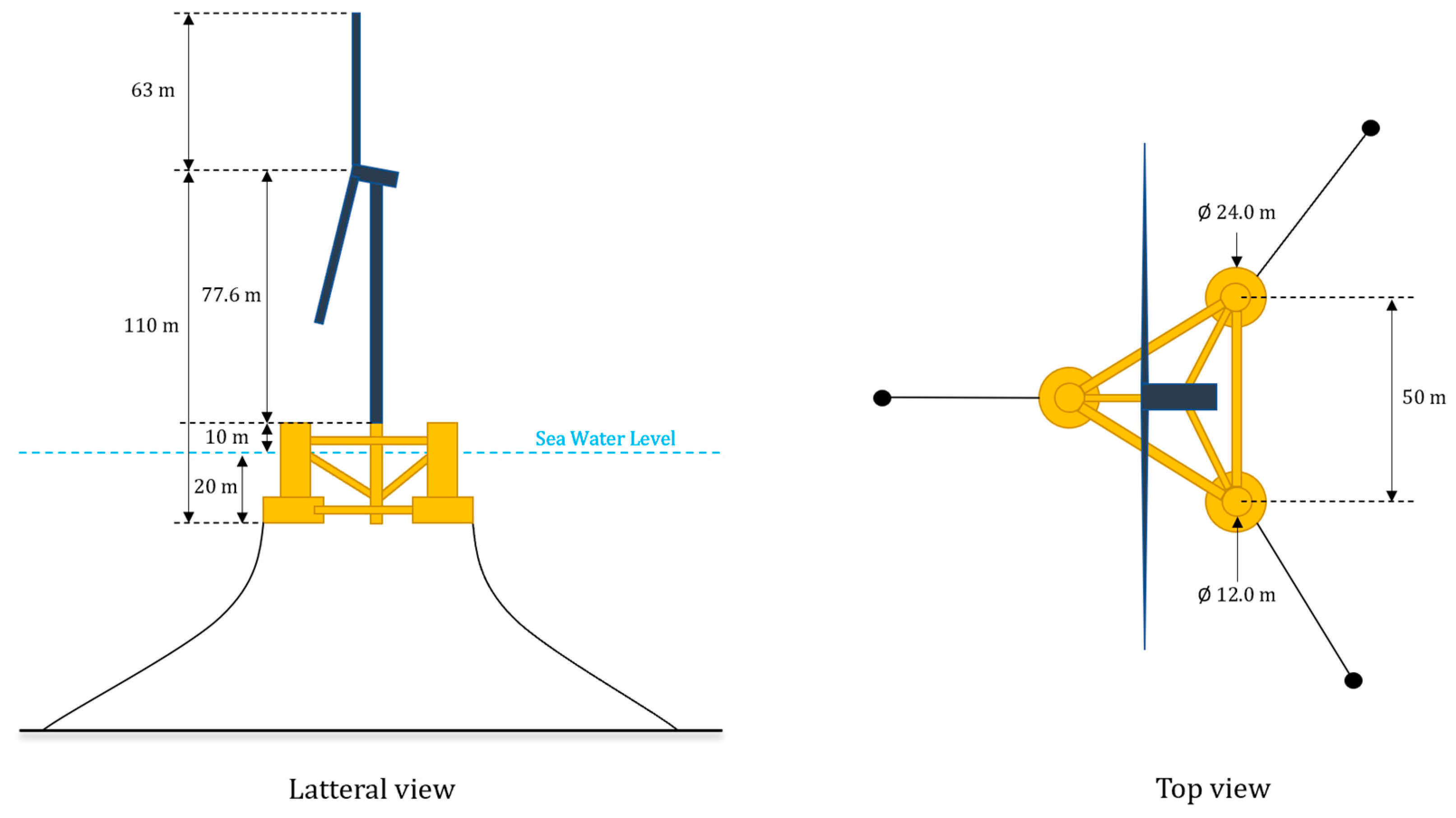
2.1. Baseline Reference System

In this study, a 5 MW three-bladed offshore wind turbine equipped with a semi-submersible platform, as illustrated in Figure 1, is utilized. This wind turbine has been developed by the National Renewable Energy Laboratory (NREL) in the United States and has been regularly utilized (with varying platform configurations) in several applications, including control design [30,34]. It consists of three cylindrical columns attached to mooring lines and a fourth one (in the center) which carries the tower. The main characteristics of the wind turbine and the floating platform are given in Table 1. Full specifications are available in [32,35].

2.2. The Numerical Model of the FOWT
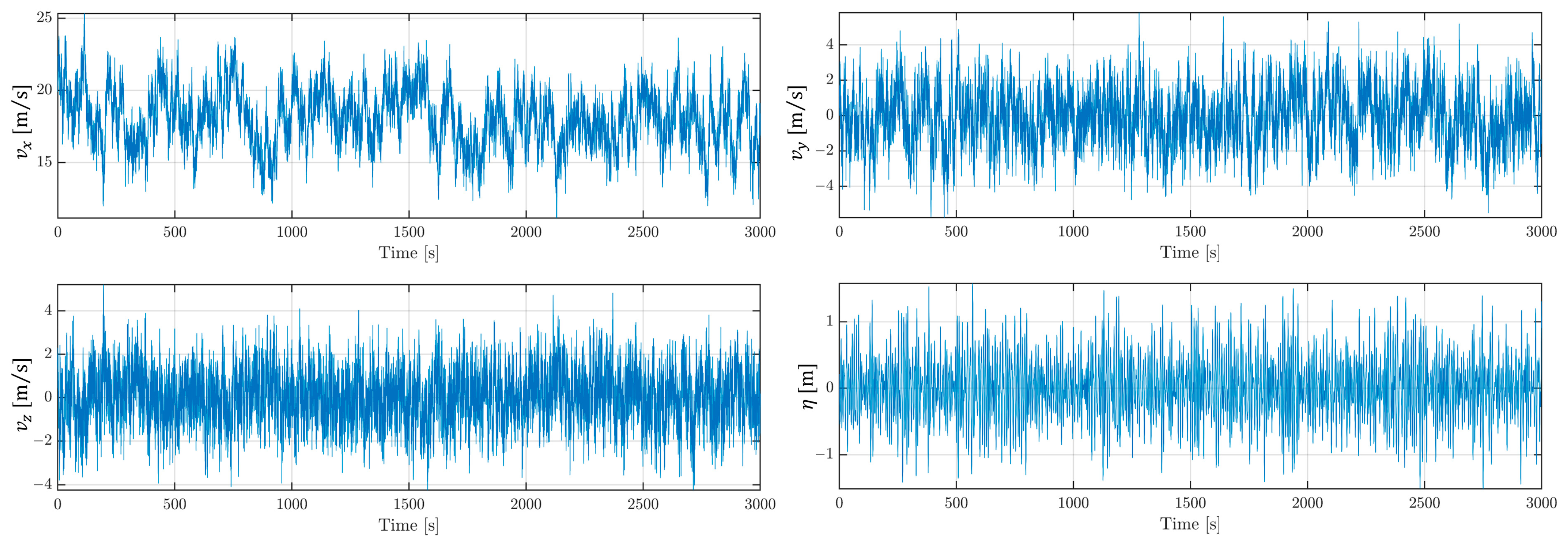
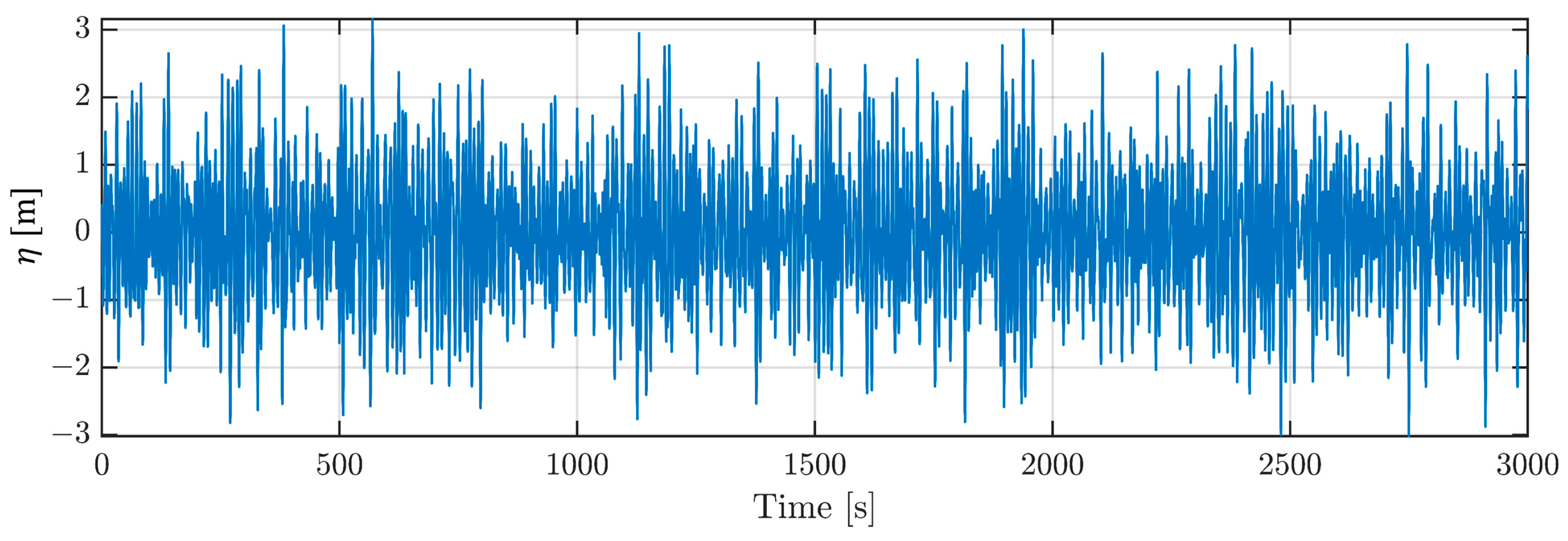
To simulate the dynamics of the FOWT subjected to wind and wave disturbances, advanced numerical models are usually required. For instance, the FAST software [36] has been extensively applied for such applications due to its high accuracy. However, these numerical models are computationally expensive due to the involved large number of degrees of freedom. Therefore, they cannot be readily integrated with probabilistic frameworks or control applications. In this study, an efficient control-oriented physics-based model of FOWT will be employed [31]. On the other hand, the OpenFAST model will be only used for validation purposes. The simplified dynamic model [31] represents the main dynamics of the FOWT with a reduced number of DOFs (six platform DOFs and two drivetrain DOFs) and states (15 in total). With the selected medium-fidelity numerical model, the computational cost will be substantially reduced which will facilitate the design of the controller. In addition, this model has been validated against FAST and was able to reproduce the main dynamics of the FOWT under wind and wave disturbances [31]. It has also been successfully used in several control studies and was demonstrated to be a reliable model [20,21,29]. The nonlinear model of the FOWT is expressed in a state-space format as follows:
x ˙ = f ( x , u , v , w )
where f is a nonlinear operator which represents the FOWT dynamics accounting for the states x , the inputs u and perturbations (i.e., wind v and wave w excitation). The states of the system x include the surge x , sway y , heave z , roll θ x , pitch θ y , yaw θ z , along with their derivatives. The rotor rotational speed ω r , generator rotational speed ω g and the shaft deflection angle Δ θ r are also accounted for as additional states. The 15 states vector can be expressed as:
x = [ x ,   y ,   z ,   θ x ,   θ y ,   θ z ,   x ˙ ,   y ˙ ,   z ˙ ,   θ ˙ x ,   θ ˙ y ,   θ ˙ z ,   ω r ,   ω g ,   Δ θ r ] T
A Newtonian approach is used to derive the model’s equations of motion in which the blades and tower structure are assumed to be rigid. Based on the equation of motion, the nonlinear function f is then expressed as:
f ( x , u , v , w ) = [ x ˙ , y   ˙ , z   ˙ , θ ˙ x ,   θ ˙ y ,   θ ˙ z , f F ,   f T ,   f Q , Δ θ ˙ r ] T
where, f F (m/s2), f T (rad/s2) and f Q (rad/s2) are respectively the sum of forces, torques, and shaft torque which are given as:
f F ( x , u , v , w ) = ( m g I 3 + d i a g [ m a ] ) 1 ( F A + F B + F C + F D )
f T ( x , u , v , w ) = ( R _ r o t I _ g 1 R _ r o t T ) ( T A + T B + T C + T D )
  f Q ( x , u , v ) = [ 1 J r ( P ω r k r ( Δ θ r ) b r ( Δ θ ˙ r ) ) 1 J g ( τ g + k r N G R ( Δ θ r ) + b r N G R ( Δ θ ˙ r ) ) ]
where F A is the aerodynamic force, F B is the buoyancy force, F C is the mooring line force and F D is the hydrodynamic drag/inertia force. In the simplified model, F A is represented by a single thrust force acting in the direction of the rotor shaft. F B is derived based on the application of Archimedes’ principle to each platform cylinder. The mooring line force F C is obtained based on the quasi-static model of a single two-dimensional cable by solving a system of two coupled nonlinear equations relating the 2-D force at the wind turbine attachment point to the vertical and horizontal distances of cable ends [37]. Finally, the hydrodynamic force F D is determined by dividing each floating column of the platform into segments and applying the Morison’s equation to get the drag and inertia forces. The vectors [ T A , T B , T C , T D ] are the corresponding torques of the above-mentioned forces acting on the center of gravity of the FOWT. In addition, m g is the total mass of the FOWT, m a is the hydrodynamic added mass vector, R _ r o t is a rotation matrix, I _ g is an inertia tensor, J r and J g are the rotor and generator inertias respectively, N G R is the gear ratio, τ g is the generator torque, k r and b r are the driveshaft stiffness and damping on rotor side respectively and P is the aerodynamic power. With a given state vector x , the new states can be calculated using a simple integration of x ˙ which is obtained by solving Equation (1). More details about the model and the necessary parameters which are required by the simulation can be acquired in [31].

2.3. Disturbances

The FOWT is subjected to both wind and wave excitation, which represent the main system disturbances. It should be noted that although ocean currents might be important in some cases, they were not accounted for in this study. The wind disturbance vector denoted as v (m/s), is the instantaneous wind speed vector which is decomposed into a mean and a fluctuating component as v = v m + v f where the vertical variation of the mean component v m can be well described by the logarithmic or power law and the turbulent component v f can be characterized by power spectral density functions (e.g., von Karman wind spectrum). On the other hand, the wave disturbance vector which is necessary to characterize the hydrodynamic interactions between the floating platform and the surrounding water is denoted as   w   and includes wave velocity, acceleration, height η and dynamic pressure at the four platform columns. Some of the characteristics can be readily retrieved from an ocean wave spectrum component (e.g., the Pierson-Moskowitz spectrum [38] or the JONSWAP spectrum [39]).

2.4. Control Inputs

Although several control strategies exist, a simplified and efficient approach is adopted here. Specifically, the aerodynamic force is directly adjusted by the proposed controller without any additional actuator. Manipulating directly the aerodynamic thrust force based on commonly known control inputs is convenient for any new or already installed FOWT since no additional hardware is required. Specifically, the FOWT has three control inputs, namely the collective blade pitch angle β , the generator torque τ g and the nacelle yaw angle γ . Therefore, the input vector u is given as:
u = [ β τ g γ ]   T
These three inputs are generally available on all modern horizontal-axis wind turbine models and will be the only control inputs used by the controller to meet the control objectives.

2.5. Control Objectives

As indicated in the block diagram of Figure 2, each FOWT will receive a reference or a target position ( x t a r , y t a r ) and power ( P t a r ) from a wind farm controller. Then, the controller related to each FOWT needs to satisfy those targets. Specifically, the control objectives of the FOWT controller consist of:
1.
Maintaining the generated power around the target value P t a r
2.
Repositioning the platform to reach a target position ( x t a r , y t a r )
3.
Limiting the platform’s oscillation motions and velocities (including the repositioning step).
It should be noted that several system constraints (which will be covered later) need to be satisfied as well to account for the system limitations and ensure a smooth and realistic system operation. In addition, the presence of wind and wave excitations will complicate the problem, therefore robust controllers are needed to meet all prescribed objectives.
One key consideration that needs to be integrated, to ensure the proper functioning of the FOWT and its controller, is the concept of movable range [40]. Specifically, it indicates the permissible region (in terms of x and y coordinates) where the constraints of power, generator speed and torque are satisfied. For example, Figure 3 shows the movable range with different power targets under a constant wind speed v m = ( 18 ,   0 ,   0 )   [ m / s ] . It can be concluded that the movable range increases with low power requirements.

3. Controller Design

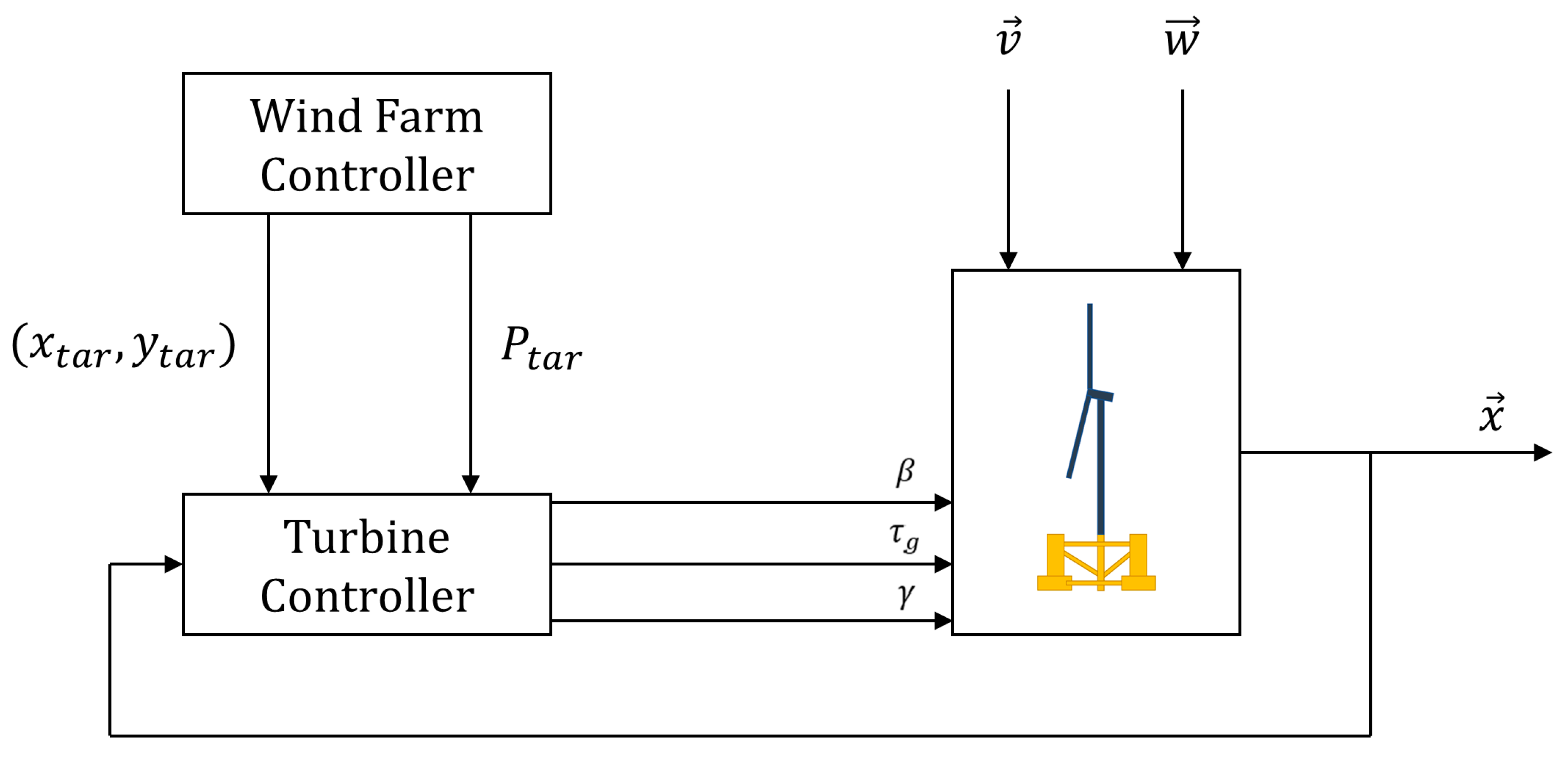
3.1. Controller Structure

The FOWT control structure (Figure 4) which is required to meet the control objectives of Section 2.5 is divided into two main subsystems, namely the power regulator, to meet the prescribed power P t a r , and the position controller is responsible for displacing the platform and mitigating the platform oscillations. Three control inputs (Section 2.4) will be generated by the controller, namely β , τ g and γ to meet the prescribed objectives. In addition, the controller can directly account for the disturbances (as illustrated by Figure 4) to facilitate its operation in the presence of environmental perturbations.

3.1.1. Power Regulator

The control law of the power regulator is based on the constant power strategy [32]. Specifically, the power regulator which provides the generator torque control input ( τ g ) to meet the target power output P t a r , prescribes τ g as:
τ g = P t a r η g ω g
where η g represents the generator’s conversion efficiency. Here, the generator speed ( ω g ) is extracted from the state vector ( x ) of the FOWT (Figure 4).

3.1.2. Position Controller

The position controller task is to reposition the FOWT platform to the target position ( x t a r , y t a r ) , which is sent by the global wind farm controller, while mitigating the platform oscillations. To achieve this goal, it receives the current position of the wind turbine as well as the states of interest (e.g., based on a network of sensors), and then generates the control input ( β ,   τ g , γ ) to modify the aerodynamic thrust force as illustrated by Figure 4. Detailed information will be provided in the next sections.

3.2. Model Predictive Controller Design

In this study, the model predictive control (MPC) is utilized, and coupled with a nonlinear dynamic model (Section 2.2), to satisfy the control objectives. Specifically, the MPC controller requires an internal model to be able to generate the control inputs corresponding to the next steps given the current system states while accounting for the system constraints. The MPC controller is designed based on a linearized model around judiciously selected equilibrium points (also denoted as operating points). Therefore, in this study, the 3D nonlinear dynamic model of the FOWT (i.e., Equation (1)) is first linearized around an equilibrium point p e q = [ x 0 ,   u 0 ,   v 0 ,   w 0 ] T by solving:
f ( x 0 , u 0 , v 0 , w 0 ) = 0
Then, the linearized model can be obtained as:
δ x ˙ = A δ x + B δ u M P C + C δ v
where δ represents the deviation of the selected quantities from the equilibrium point, u M P C = [ β γ ] T are the MPC control inputs, and A , B and C are the equivalent linearized matrices. The matrices A , B and C , which are time-invariant, are retrieved by evaluating the Jacobians of the function f at the equilibrium point p e q as:
A = f x | p e q B = f u M P C | p e q C = f v | p e q
It should be noted that only the wind speed v has been used to derive the linearized model, hence neglecting the wave fluctuations due to the practical considerations related to the real-time measurement [20]. Moreover, the selection of a convenient equilibrium point is crucial. Therefore, it is essential to carefully select a relevant point which can accommodate a large area with several operational scenarios within the movable range. To find the optimal control inputs, the system outputs are iteratively determined over a prediction horizon ( N p ), and the control inputs are specified over the control horizon ( N m ) which are subsequently used to minimize the cost function J at each time step while accounting for the system constraints. The cost function J is expressed as:
J = k = i + 1 i + N p Q [ y k y r e f ] 2 + k = i i + N m 1 R [ u M P C , k u M P C , k 1 ] 2  
where Q and R are weight matrices related to the MPC states and input variables, respectively and y is the output vector which should match the target vector y r e f once the cost function has been minimized. The y vector is expressed as:
y = [ x ,   y ,   ω g ,   θ ˙ x ,   θ ˙ y ] T
Therefore, the cost function is designed to penalize the position error, fluctuations around ω g (to prevent system instabilities), platform oscillations through the matrix Q and excessive use of the control inputs (i.e., blade pitch and nacelle yaw) through the matrix R . The cost function J is also subjected to several constraints at each time step k as:
{ x m i n x k x m a x y m i n y k y m a x ω g m i n ω g k ω g m a x θ x m i n θ x k θ x m a x θ y m i n θ y k θ y m a x u M P C m i n u M P C k u M P C m a x u ˙ M P C m i n u ˙ M P C k u ˙ M P C m a x
where ( u M P C m i n , u M P C m a x ) & ( u ˙ M P C m i n , u ˙ M P C m a x ) represent the saturation and rate limits of the control inputs, respectively, ( x m i n ,   x m a x ) & ( y m i n ,   y m a x ) represent the minimum and maximum permissible horizontal displacement of the platform in the x and y directions, respectively, ( ω g m i n ,   ω g m a x ) represent the minimum and maximum permissible generator rotational speeds and ( θ x m i n ,   θ x m a x ) & ( θ y m i n ,   θ y m a x ) are the limits of the platform rotation in the roll and pitch directions, respectively. The minimization of the cost function is achieved based on the “Knows What It Knows” or KWIK active-set algorithm [41].

4. Case Study

To demonstrate the robustness of the MPC controller, a scenario regrouping all control objectives (Section 2.5) will be evaluated using OpenFAST [33] and Matlab/Simulink. This scenario was designed to evaluate the capacity of the proposed controller to perform the requested tasks, including the platform repositioning, power regulation and structural stability (e.g., limitation of platform roll and pitch angles along with their respective platform roll and pitch velocities). In addition, the predefined constraints of Equation (14) are imposed on the controller in which the minimum and maximum limits for x and y were selected to first include the movable range and then keep the turbine in a safe zone (e.g., to avoid the collision with other turbines in the wind farm). The constraints on ω g were chosen to maintain the turbine in its operating range [32] and those related to the platform roll and pitch angles were selected to ensure the structural integrity and safety of the FOWT [42]. The selected constraints are shown in Table 2.
In addition, to incorporate the physical limitations of the control inputs (i.e., β ,   τ g and γ ), saturation and rate-limit need to be accounted for during the control process [32]. These limits are shown in Table 3.
The necessary controller parameters for the selected scenario are summarized in Appendix A. The prediction and control horizons as well as the sample time of the MPC controller have been chosen as a compromise between performance and computation cost. It should be noted that a single linearized model was sufficient for the MPC controller where the equilibrium point was strategically selected at the center of the movable range to cover the entire region. Indeed, Ref. [43] shows that there is a monotonic behavior between the equilibrium points and the control inputs. In some scenarios, it might be necessary to linearize the model using several equilibrium points (each covering a specific zone in the movable range). The controller will then switch between the equilibrium points once the target position falls within the range of a new equilibrium point. However, it was not necessary here as it will be shown for the case study (more details about the selected equilibrium point and associated parameters are presented in Appendix A). In addition, to highlight the superior performance of the proposed controller, it will be compared with a typical PID controller which was empirically tuned by Han and Nagamune [20]. Similarly, the PID parameters are given in Appendix A. The selected scenario is summarized as follows:
Scenario: Repositioning the platform to different target coordinates while generating the requested power at each location and limiting the platform’s oscillation motions during its movement. The last target will be maintained over a longer period of time while generating a single power target and ensuring its structural stability (in terms of the platform pitch and roll).
For this scenario, a random starting point will be selected. Furthermore, realistic offshore wind and wave conditions were obtained using the Von Karman turbulence spectrum and the Pierson–Moskowitz spectrum [38], respectively. The mean wind components are selected as v m = [ 18 ,   0 ,   0 ] T   [ m / s ] which are prescribed at the hub height with superimposed fluctuations in each direction with a turbulent intensity I u , v , w = [ 0.087 ,     0.087 ,     0.084 ] and integral length scale L u , v , w x = [ 170 ,     80 ,     80 ] [m] along the wind direction. It should be mentioned that in the case of very low wind speed values, the repositioning mechanism based on the direct manipulation of the thrust force might not be effective. Actually, this mechanism relies essentially on the balance of forces including the aerodynamic thrust force and the restoring force from the mooring lines. Hence, for low wind speeds, the thrust force may be too low to compensate for the effects of other forces such as those induced by the mooring lines. It would be then impractical to reach certain target positions with a given power demand [21]. To alleviate some of these problems, one possible solution would be to increase the mooring line lengths which will eventually decrease the magnitude of the restoration force and enlarge the movable range. Additional actuators could also be installed to assist the wind turbine in repositioning during those conditions. The irregular waves were set to propagate along the nominal wind direction without consideration of ocean currents with a significant wave height H s = 2   [ m ] and a peak spectral period T p = 10   [ s ] . Both wind and wave disturbances are shown in Figure 5.
Five different and permissible locations within the movable range are selected while considering the safety limits of the nacelle yaw angle [16]. For each target location, a target power has been prescribed for the controller. In addition, for all the selected scenarios, the target values for the roll and pitch velocities are 0°/s to reduce the movement oscillations. Detailed information about the target values for both position and power is summarized in Table 4.
Finally, in Section 4.6, the same scenario will be repeated for a more severe sea state (i.e., with a significant wave height   H s = 4   [ m ] ) to demonstrate the ability and robustness of the MPC controller to mitigate the oscillations of the platform under extreme environmental conditions.

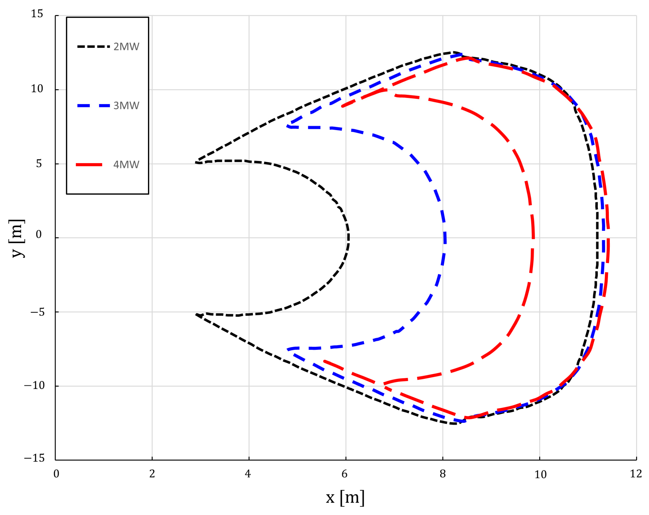
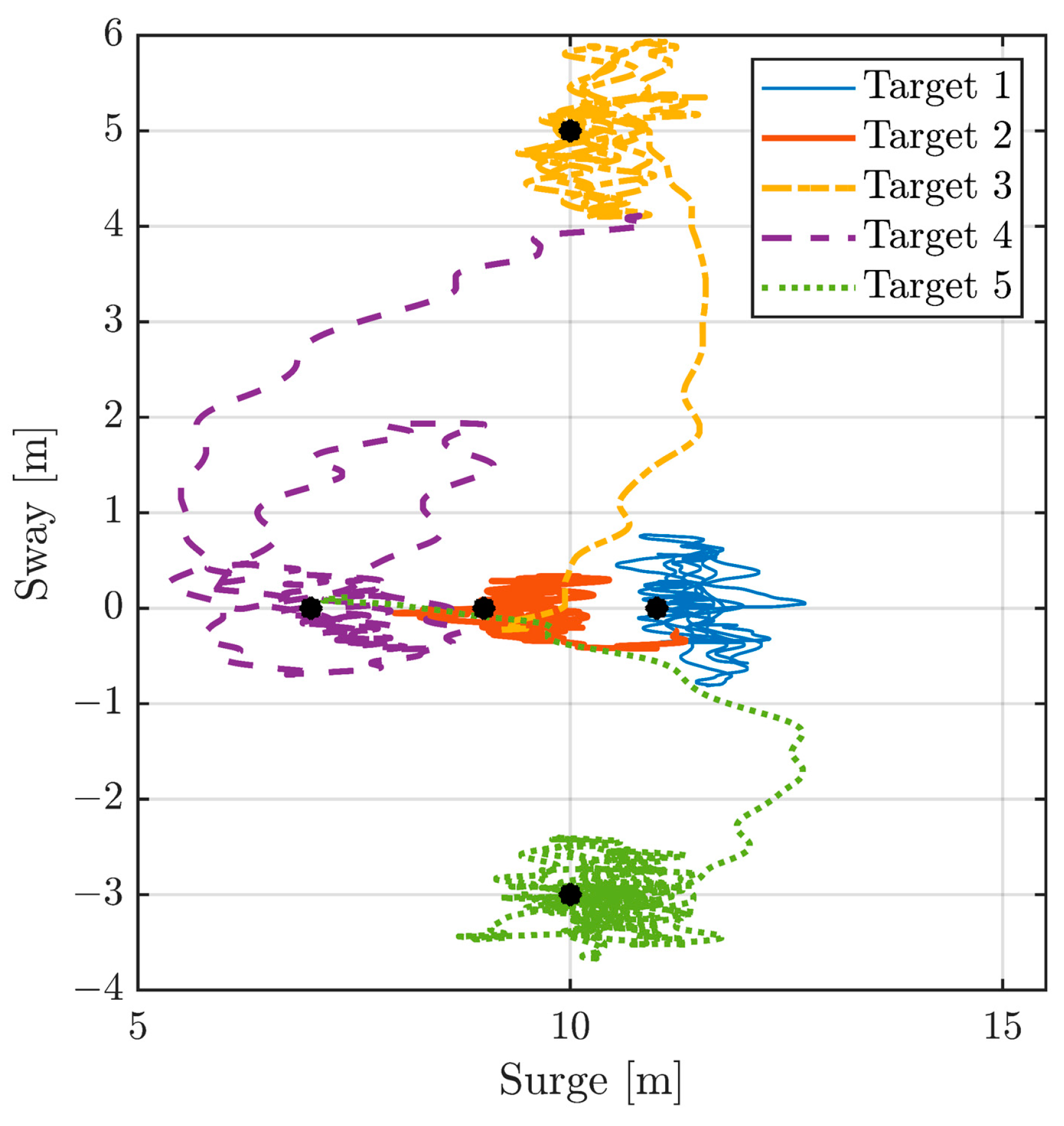
4.1. Position Control Results

The time series results (surge and sway) for both the MPC and PID controllers are shown in Figure 6. As can be concluded, the MPC outperforms the PID controller in tracking the target position. Actually, the PID was not even able to get to the 5th target position. This can be attributed to the inherent limitations of the PID controller which cannot perfectly control the position while maintaining a reasonable rotor speed for all scenarios (in this case for negative sway targets). In fact, the PID parameters could be potentially further tuned to achieve the 5th target position but it might not be suitable for other target locations. System instabilities have also been reported for PID controllers when they were made more aggressive [20] to achieve similar control objectives of this study. In addition, PIDs are based on the single-input-single-output principle and cannot handle system constraints which makes them difficult to control a constrained system with coupled inputs (usually several PIDs are integrated with each one of them being independent of the other).
In addition, the magnitude of the fluctuations of the FOWT surge and sway motions, which are inevitable due to the wind and wave excitations, are less pronounced for the MPC compared to the PID controller. Furthermore, the required time to reach each target position was less for the MPC compared to PID, making it more suitable for real-time operations. As an example, reaching targets #3 and #4 required almost 60 [ s ] and 160 [ s ] , respectively for the MPC controller compared to a duration time exceeding 500 [ s ] with a PID controller for both targets. However, it is expected that the MPC simulation results could be even better if an advanced MPC internal predictive model has been used. In fact, a simplified linearized model [31] was used in this study, therefore it might not be compatible with the FAST model (e.g., for the calculation of the thrust force) which was implemented here as the ‘external’ plant model.
The FOWT trajectory for all target positions is also depicted in Figure 7 based on the proposed MPC controller. As indicated in Figure 7, the controller has successfully repositioned the platform to reach the prescribed targets.
It should be noted that for the MPC control simulations, the computational time was around 174 [ s ] when the structural response is simulated using the simplified 3D nonlinear model and increased to reach almost 1788 [ s ] when FAST has been used instead to complete the 3000 [ s ] scenario. For the rest of Section 4, only the MPC results will be presented since similar conclusions were obtained for the PID controller with superior performances for MPC.

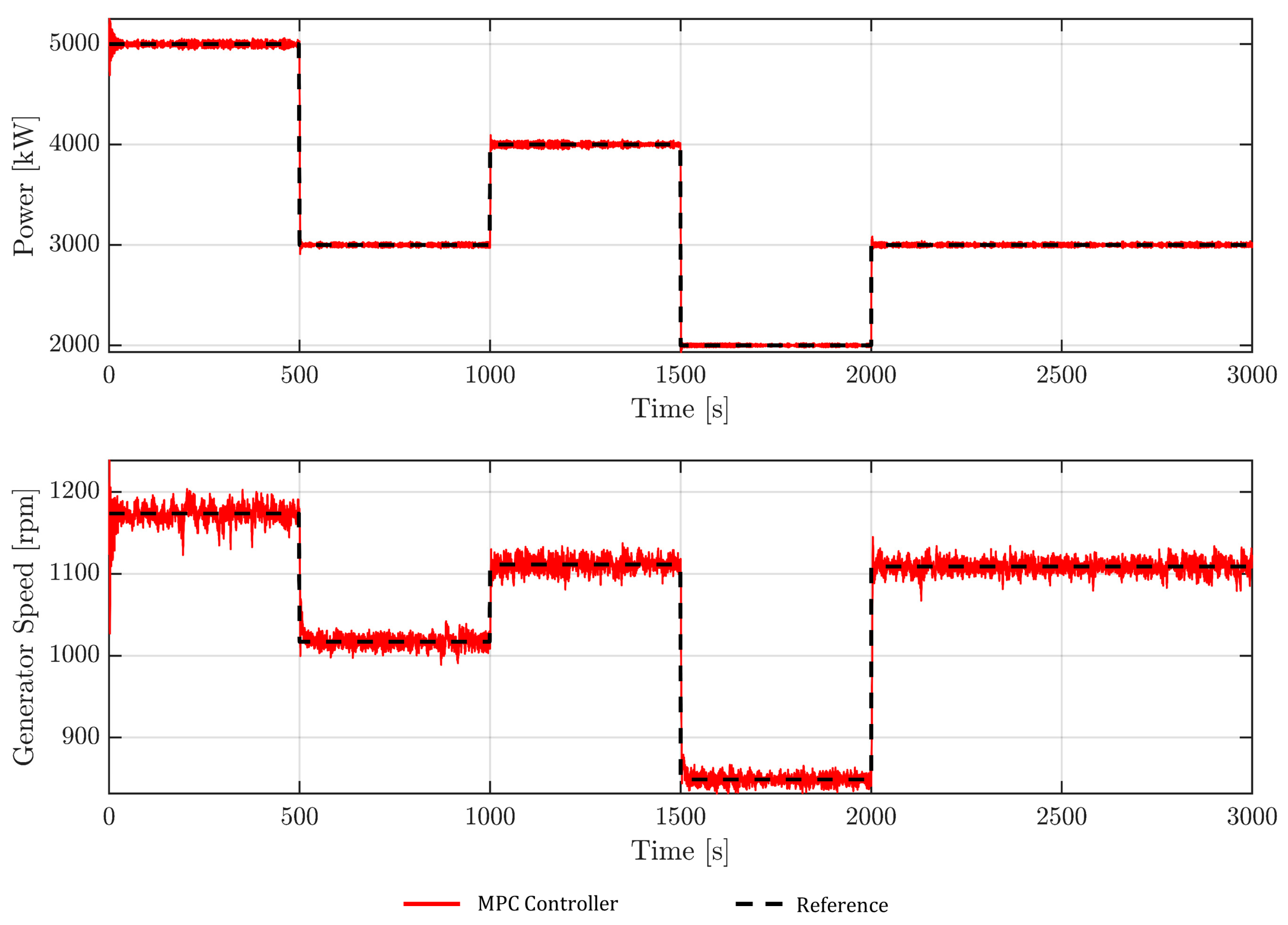
4.2. Power and Generator Speed Control Results

The time series results for the power and generator speed are shown in Figure 8. The obtained results indicate that the power regulator was successful in tracking the target powers rapidly which is necessary for real-time applications in which the power production must be rapidly adapted to meet the power demand from the grid. On the other hand, there are still some fluctuations around the target values which are primarily due to wind and wave perturbations.

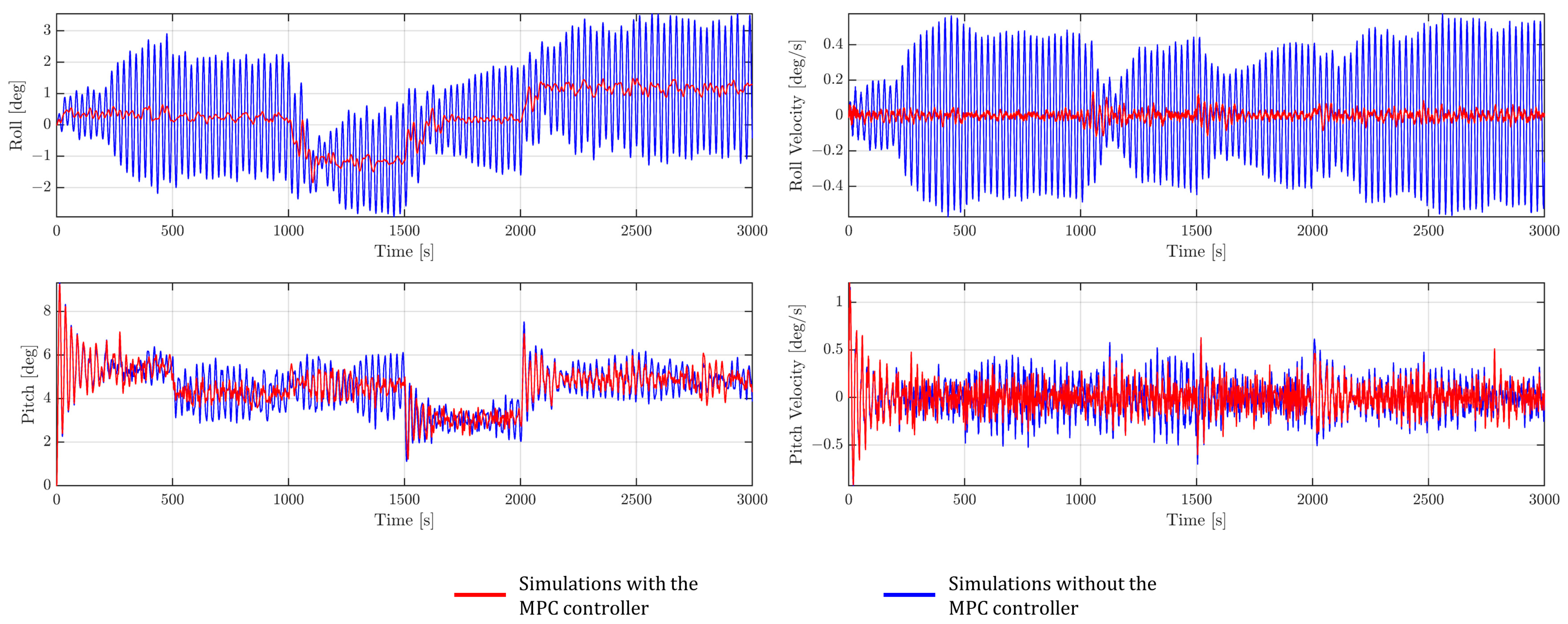
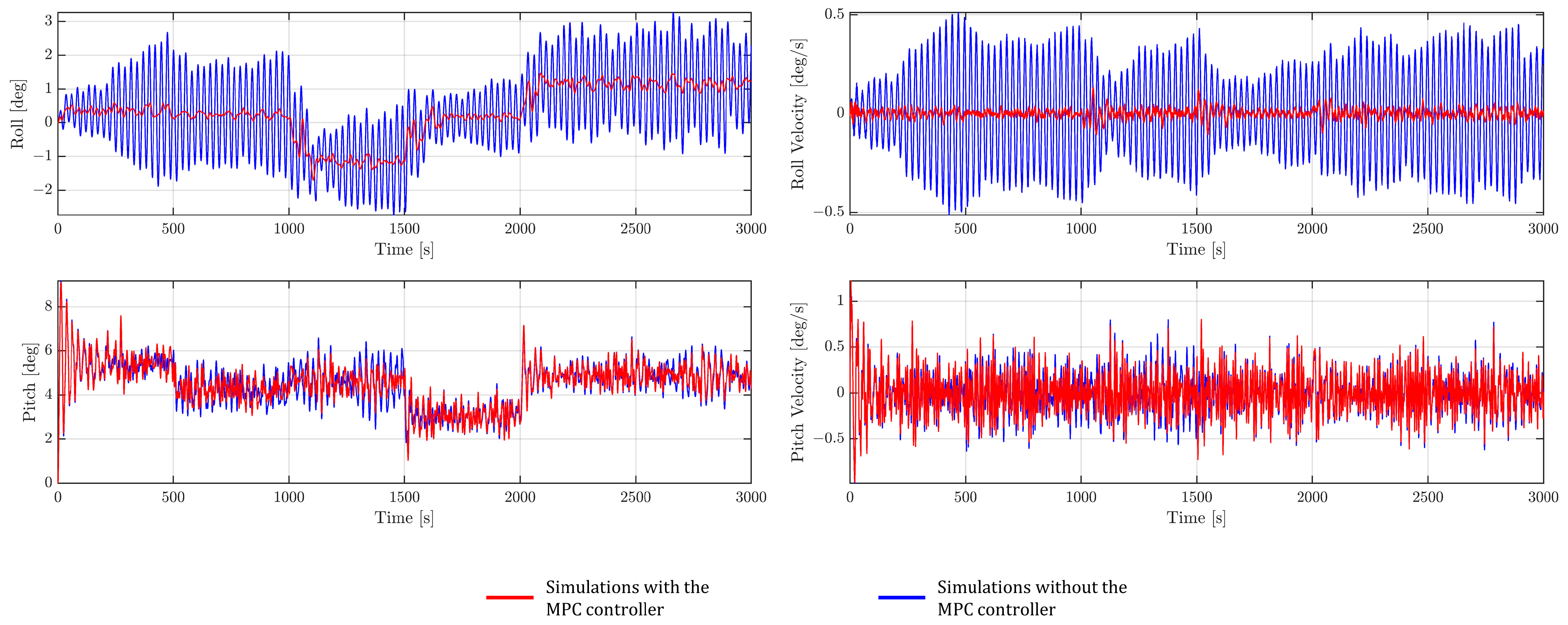
4.3. Platform Rotational Motion and Oscillation Results

The time domain simulation results of the platform roll and pitch angles along with the platform roll and pitch velocities considering the wind and wave perturbations are depicted in Figure 9. Specifically, two simulations have been conducted: first, the MPC controller was asked to only regulate the turbine position and power without considering the platform roll and pitch (i.e., the weights related to the platform roll and pitch velocities are set to zero in the Q matrix and the constraints on the platform roll and pitch angles are removed); second, the MPC was asked to achieve all the control objectives and meet all constraints including those related to the roll and pitch angles and velocities. Based on the results of Figure 9, it can be concluded that the MPC controller can substantially reduce the platform oscillations while keeping the platform roll and pitch angles below the limit of 10 degrees, which ensures the platform’s stability against environmental perturbations. It should be noted that the observed jump in the roll velocity (for the second simulation) happens during the change in the target position (especially for sway) which might be essentially due to the sudden displacement in the sway direction. However, the MPC controller was able to quickly dampen those relatively large velocities. A similar conclusion can be made for the platform pitch velocity which is higher than the platform roll velocity due to the high wind speed values along the surge direction.

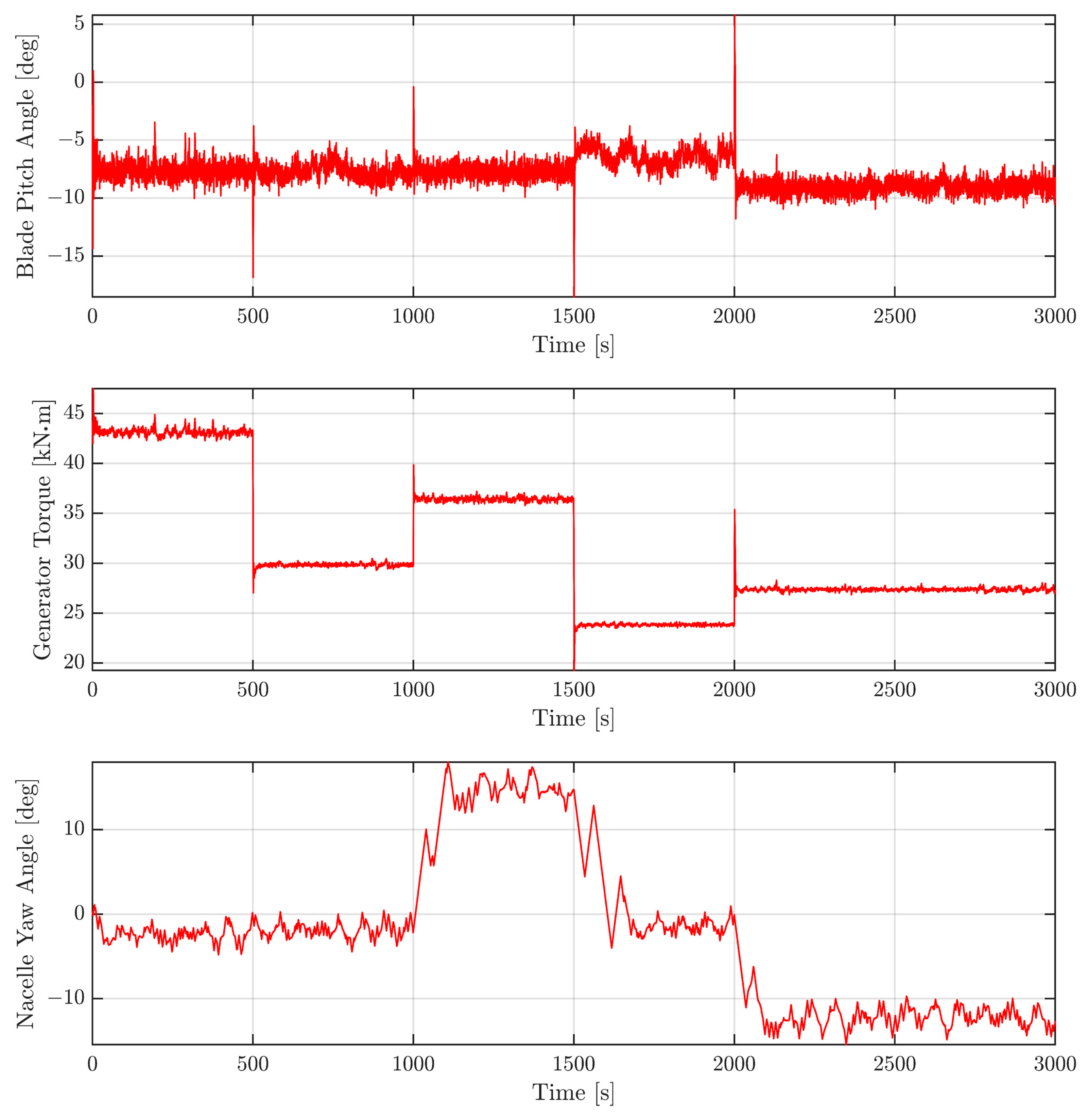
4.4. Control Inputs Results

The time series of the control inputs were also plotted in Figure 10. It can be observed that the nacelle’s yaw angle is kept within the specified safety limits [16]. In addition, the yaw angle time series follow a similar trend as the target sways. Similarly, the collective blade pitch angle and generator torque are within the specified limits and were rapidly adjusted by the MPC controller to reach the prescribed control objective. However, a sudden jump in both the blade pitch and generator torque can be observed at the onset of the next target position command. This can be attributed to the sudden increase/decrease of the target power which forces the generator torque to change suddenly as well. Therefore, the blade pitch should also significantly increase/decrease to change the lift force and avoid any rotor interruption or stalling [44].

4.5. Quantitative Comparison of the Controllers’ Performances

As indicated in the previous sections, the MPC model has successfully controlled the FOWT and met all control objectives. To assess the performance of the MPC controller quantitatively, the results will be evaluated in terms of the root-mean-square error (RMSE). Table 5 summarises the RMSE values for the position, power, platform roll and pitch velocities. The RMSE values are calculated with respect to the target position and power. In addition, they were calculated with respect to the value of zero for the platform roll and pitch velocities. It should be noted that for a fair comparison, the RMSE values are reported for the simulations up to 2000 [ s ] since the PID was not even able to get to the 5th target position (therefore it will lead to very large errors). The low RMSE values highlight the superior control capacities of the MPC model which can satisfy several control objectives while accounting for the system constraints compared to standard controllers, such as the PID model.

4.6. MPC Performance under Severe Environmental Conditions

In this section, the previous scenario will be again repeated but with a more severe sea state condition which could arise due to the effects of storm events or climate change (i.e., with a significant wave height   H s = 4   [ m ] and a peak spectral period T p = 10   [ s ] ) [45,46,47]. Only the simulation results related to the platform roll and pitch along with its roll and pitch velocities will be shown here since comparable simulation results as the previous scenario was obtained. The time series of the wave elevation is shown in Figure 11.
The time domain simulation results of the platform roll and pitch angles along with the roll and pitch velocities are depicted in Figure 12. Similar to Section 4.3, two scenarios have been conducted (i.e., with and without the MPC controller). Based on the results of Figure 12, it can be concluded that although the platform oscillations have increased (compared to Section 4.3) due to the rough sea conditions, the MPC has still managed to keep the roll and pitch angles within their permissible limits. In addition, without the MPC, the platform oscillations were substantial which jeopardizes structural integrity. It is also important to note that the attenuation of the pitching oscillations is not easy to achieve as the wave amplitude increases. Indeed, the worst case is considered here since the direction of the waves is purely perpendicular to the platform pitch rotation axis. For larger waves, manipulating only the thrust force using the three control inputs to decrease these oscillations might not be sufficient, as the hydrodynamic forces increase substantially compared to the aerodynamic forces used by the MPC controller to regulate the turbine.
The numerical performance of the MPC controller for this scenario is also summarized in Table 6.

5. Conclusions

In this study, a model predictive control (MPC) has been proposed for floating offshore wind turbines (FOWTs) to achieve three main goals, that is, (1) to regulate the power production, (2) to reposition the FOWTs to reach predefined target positions, and (3) to ensure their structural stability (e.g., preventing excessive platform rotations). The direct manipulation of the aerodynamic thrust force is adopted here, without additional actuators, as the control strategy. Specifically, three control inputs are used, namely the nacelle yaw angle, the collective blade pitch angle, and the generator torque. The considered environmental perturbations are the wind and wave excitations. Several constraints have been accounted for in the design of the MPC model. In addition, a simplified nonlinear 3D model has been used as the internal MPC predictive model to ensure real-time repositioning and power control. A realistic scenario corresponding to a 5-MW reference FOWT has been simulated under mild and severe sea conditions to demonstrate the robustness of the proposed MPC controller. Specifically, five different and permissible locations within the movable range have been selected while considering the safety limits on the FOWTs parameters. For each target location, a target power has been prescribed for the controller. In addition, the proposed model was compared with the PID controller. The first simulation results indicated that the MPC model outperforms the PID controller in tracking the target position and power while ensuring structural stability. For instance, the generated RMSE value was 1.2 [m] for MPC compared to 2.1 [m] for PID. Furthermore, due to its rapid response time, the MPC controller is applicable for real-time applications. Finally, the second simulation, considering a severe sea condition, shows the ability of the controller to operate under severe environmental conditions while achieving different objectives. The proposed controller can be readily integrated within new or operational wind farms without the need for additional hardware (e.g., actuators).

Author Contributions

Conceptualization, T.J. and R.S.; methodology, T.J. and R.S.; software, T.J.; validation, T.J. and R.S.; formal analysis, T.J. and R.S.; investigation, T.J. and R.S.; data curation, T.J.; writing−original draft preparation, T.J.; writing−review and editing, R.S.; visualization T.J.; supervision, R.S. All authors have read and agreed to the published version of the manuscript.

Funding

This research was funded by Natural Sciences and Engineering Research Council, grant number 2022-03492.

Institutional Review Board Statement

Not applicable.

Informed Consent Statement

Not applicable.

Data Availability Statement

Specifications for the 5 MW reference offshore wind turbine are publicly available as noted in this article. All other necessary parameters have been explicitly reported in the article.

Conflicts of Interest

The authors declare no conflict of interest.

Appendix A. Controller Parameters

This appendix presents all the gains and parameters for both MPC and PID controllers used in the control scenario and simulation of Section 4.
The identified equilibrium point used for the MPC’s prediction model was obtained by considering a constant wind speed v 0 = [ 18 0 0 ] T [m/s] and a still water ( w 0 = 0 ) is:
x 0 = [ 9   [ m ] 0   [ m ] 9.945   [ m ] 0.007   [ deg ] 0.074   [ deg ] 0.005   [ deg ] 0   [ m / s ] 0   [ m / s ] 0   [ m / s ] 0   [ deg / s ] 0   [ deg / s ] 0   [ deg / s ] 1.098   [ rad / s ] 106.498   [ rad / s ] 0.003   [ deg ] ]       u 0 = [ −7.947   [ deg ] 29,820.465   [ Nm ] 0.023   [ deg ] ]
The additional parameters which are required by the MPC controller are the sample time, the prediction horizon and the control horizon were 0.2 [s], 150, and 20, respectively. The MPC weight matrices (i.e., Q and R which are associated with the controlled variable y) are given as:
Q = [ 20 0 0 0 0 0 100 0 0 0 0 0 180 0 0 0 0 0 600 0 0 0 0 0 200 ]                           R = [ 200 0 0 30 ]
The PID gains (as specified in [20]) are:
K p , P I D = diag [ 10 9 , 2 × 10 3 , 0.5 ]
K i , P I D = diag [ 10 9 , 10 4 , 10 3 ]
K d , P I D = diag [ 5 × 10 11 ,   0 ,   0.3 ]

References

  1. Musial, W.; Beiter, P.; Spitsen, P.; Nunemaker, J.; Gevorgian, V.; Cooperman, A.; Hammond, R.; Shields, M. 2019 Offshore Wind Technology Data Update; NREL/TP-5000-77411; National Renewable Energy Laboratory (NREL): Golden, CO, USA, 2020. [Google Scholar]
  2. GWEC. Global Wind Report 2021; Global Wind Energy Council: Brussels, Belgium, 2021; Available online: https://gwec.net/global-wind-report-2021/ (accessed on 4 October 2022).
  3. Jonkman, J.M. Dynamics Modeling and Loads Analysis of an Offshore Floating Wind Turbine. Ph.D. Thesis, Department of Aerospace Engineering Sciences, University of Colorado, Boulder, CO, USA, National Renewable Energy Laboratory, Golden, CO, USA, 2007. [Google Scholar]
  4. Swart, R.; Coppens, C.; Gordjin, H.; Piek, M.; Ruyssenaars, P.; Schrander, J.J.; Hoogwijk, M.; Papalexandrou, M.; Horalek, J. Europe’s Onshore Andoffshore Wind Energy Potential: An Assessment of Environmental and Economic Constraints. (No. 6/2009); European Environment Agency: København, Denmark, 2009. [Google Scholar]
  5. Shah, K.A.; Meng, F.; Li, Y.; Nagamune, R.; Zhou, Y.; Ren, Z.; Jiang, Z. A Synthesis of Feasible Control Methods for Floating Offshore Wind Turbine System Dynamics. Renew. Sustain. Energy Rev. 2021, 151, 111525. [Google Scholar] [CrossRef]
  6. Stehly, T.; Beiter, P. 2018 Cost of Wind Energy Review (Technical Report); NREL/TP-5000-74598; National Renewable Energy Laboratory (NREL): Golden, CO, USA, 2019. [Google Scholar]
  7. Barthelmie, R.J.; Hansen, K.; Frandsen, S.T.; Rathmann, O.; Schepers, J.G.; Schlez, W.; Phillips, J.; Rados, K.; Zervos, A.; Politis, E.S.; et al. Modelling and Measuring Flow and Wind Turbine Wakes in Large Wind Farms Offshore. Wind. Energy 2009, 12, 431–444. [Google Scholar] [CrossRef]
  8. Vermeer, L.J.; Sørensen, J.N.; Crespo, A. Wind Turbine Wake Aerodynamics. Prog. Aerosp. Sci. 2003, 39, 467–510. [Google Scholar] [CrossRef]
  9. Porté-Agel, F.; Wu, Y.-T.; Chen, C.-H. A Numerical Study of the Effects of Wind Direction on Turbine Wakes and Power Losses in a Large Wind Farm. Energies 2013, 6, 5297–5313. [Google Scholar] [CrossRef] [Green Version]
  10. Fleming, P.A.; Gebraad, P.M.O.; Lee, S.; van Wingerden, J.-W.; Johnson, K.; Churchfield, M.; Michalakes, J.; Spalart, P.; Moriarty, P. Evaluating Techniques for Redirecting Turbine Wakes Using SOWFA. Renew. Energy 2014, 70, 211–218. [Google Scholar] [CrossRef]
  11. Steinbuch, M.; de Boer, W.W.; Bosgra, O.H.; Peters, S.A.W.M.; Ploeg, J. Optimal Control of Wind Power Plants. J. Wind. Eng. Ind. Aerodyn. 1988, 27, 237–246. [Google Scholar] [CrossRef]
  12. Wagenaar, J.W.; Machielse, L.; Schepers, J. Controlling wind in ECN’s scaled wind farm. In Proceedings of the European Wind Energy Association (EWEA) Annual Event, Oldenburg, Germany, 16–19 April 2012; pp. 685–694. [Google Scholar]
  13. Jiménez, Á.; Crespo, A.; Migoya, E. Application of a LES Technique to Characterize the Wake Deflection of a Wind Turbine in Yaw. Wind. Energy 2009, 13, 559–572. [Google Scholar] [CrossRef]
  14. Guntur, S.; Troldborg, N.; Gaunaa, M. Application of Engineering Models to Predict Wake Deflection Due to a Tilted Wind Turbine. In Proceedings of the EWEC 2012—European Wind Energy Conference & Exhibition, Copenhagen, Denmark, 16–19 April 2012. [Google Scholar]
  15. Fleming, P.; Gebraad, P.M.O.; Lee, S.; van Wingerden, J.-W.; Johnson, K.; Churchfield, M.; Michalakes, J.; Spalart, P.; Moriarty, P. Simulation Comparison of Wake Mitigation Control Strategies for a Two-Turbine Case. Wind. Energy 2015, 18, 2135–2143. [Google Scholar] [CrossRef]
  16. Kheirabadi, A.C.; Nagamune, R. Modeling and Power Optimization of Floating Offshore Wind Farms with Yaw and Induction-Based Turbine Repositioning. In Proceedings of the 2019 American Control Conference (ACC), Philadelphia, PA, USA, 10–12 July 2019; pp. 5458–5463. [Google Scholar]
  17. Kheirabadi, A.C.; Nagamune, R. Real-Time Relocation of Floating Offshore Wind Turbine Platforms for Wind Farm Efficiency Maximization: An Assessment of Feasibility and Steady-State Potential. Ocean Eng. 2020, 208, 107445. [Google Scholar] [CrossRef]
  18. Rodrigues, S.F.; Teixeira Pinto, R.; Soleimanzadeh, M.; Bosman, P.A.N.; Bauer, P. Wake Losses Optimization of Offshore Wind Farms with Moveable Floating Wind Turbines. Energy Convers. Manag. 2015, 89, 933–941. [Google Scholar] [CrossRef] [Green Version]
  19. Gao, Y.; Padmanabhan, A.; Chen, O.; Kheirabadi, A.C.; Nagamune, R. A Baseline Repositioning Controller for a Floating Offshore Wind Farm. In Proceedings of the 2022 American Control Conference (ACC), Atlanta, GA, USA, 8 June 2022; pp. 4224–4229. [Google Scholar]
  20. Han, C.; Nagamune, R. Platform Position Control of Floating Wind Turbines Using Aerodynamic Force. Renew. Energy 2020, 151, 896–907. [Google Scholar] [CrossRef]
  21. Escobar Aquino, E.E.; Nagamune, R. H∞ Position Transfer and Regulation for Floating Offshore Wind Turbines. Control Theory Technol. 2020, 18, 231–245. [Google Scholar] [CrossRef]
  22. Xu, S.; Murai, M.; Wang, X.; Takahashi, K. A Novel Conceptual Design of a Dynamically Positioned Floating Wind Turbine. Ocean Eng. 2021, 221, 108528. [Google Scholar] [CrossRef]
  23. Li, Y.; Wu, Z. Stabilization of Floating Offshore Wind Turbines by Artificial Muscle Based Active Mooring Line Force Control. In Proceedings of the 2016 American Control Conference (ACC), Boston, MA, USA, 6–8 July 2016; pp. 2277–2282. [Google Scholar]
  24. Sierra-Garcia, J.E.; Santos, M.; Pandit, R. Wind Turbine Pitch Reinforcement Learning Control Improved by PID Regulator and Learning Observer. Eng. Appl. Artif. Intell. 2022, 111, 104769. [Google Scholar] [CrossRef]
  25. Zhang, J.; Zhao, X.; Wei, X. Reinforcement Learning-Based Structural Control of Floating Wind Turbines. IEEE Trans. Syst. Man Cybern. Syst. 2022, 52, 1603–1613. [Google Scholar] [CrossRef]
  26. Wu, T.; Snaiki, R. Applications of Machine Learning to Wind Engineering. Front. Built Environ. 2022, 8, 811460. [Google Scholar] [CrossRef]
  27. Li, S.; Snaiki, R.; Wu, T. Active Simulation of Transient Wind Field in a Multiple-Fan Wind Tunnel via Deep Reinforcement Learning. J. Eng. Mech. 2021, 147, 04021056. [Google Scholar] [CrossRef]
  28. Li, S.; Snaiki, R.; Wu, T. A Knowledge-enhanced Deep Reinforcement Learning-based Shape Optimizer for Aerodynamic Mitigation of Wind-sensitive Structures. Comput.-Aided Civ. Infrastruct. Eng. 2021, 36, 733–746. [Google Scholar] [CrossRef]
  29. Shah, K.A.; Li, Y.; Nagamune, R.; Zhou, Y.; Ur Rehman, W. Platform Motion Minimization Using Model Predictive Control of a Floating Offshore Wind Turbine. Theor. Appl. Mech. Lett. 2021, 11, 100295. [Google Scholar] [CrossRef]
  30. Raach, S.; Schlipf, D.; Sandner, F.; Matha, D.; Cheng, P.W. Nonlinear Model Predictive Control of Floating Wind Turbines with Individual Pitch Control. In Proceedings of the 2014 American Control Conference, Portland, OR, USA, 4–6 June 2014; pp. 4434–4439. [Google Scholar]
  31. Homer, J.R.; Nagamune, R. Physics-Based 3-D Control-Oriented Modeling of Floating Wind Turbines. IEEE Trans. Control Syst. Technol. 2018, 26, 14–26. [Google Scholar] [CrossRef]
  32. Jonkman, J.; Butterfield, S.; Musial, W.; Scott, G. Definition of a 5-MW Reference Wind Turbine for Offshore System Development; NREL/TP-500-38060, 947422; National Renewable Energy Laboratory (NREL): Golden, CO, USA, 2009. [Google Scholar]
  33. Buhl, M.; Greg, H.; Jason, J.; Bonnie, J.; Rafael, M.; Andy, P. Mike Sprague OpenFAST. Available online: https://github.com/OpenFAST/openfast (accessed on 2 January 2023).
  34. Namik, H.; Stol, K. Individual Blade Pitch Control of Floating Offshore Wind Turbines. Wind Energy 2010, 13, 74–85. [Google Scholar] [CrossRef]
  35. Robertson, A.; Jonkman, J.; Masciola, M.; Song, H.; Goupee, A.; Coulling, A.; Luan, C. Definition of the Semisubmersible Floating System for Phase II of OC4; NREL/TP-5000-60601, 1155123; National Renewable Energy Laboratory: Golden, CO, USA, 2014. [Google Scholar]
  36. Jonkman, J.M.; Buhl, M.L., Jr. FAST User’s Guide-Updated August 2005; NREL/TP-500-38230, 15020796; National Renewable Energy Laboratory: Golden, CO, USA, 2005. [Google Scholar]
  37. Jonkman, J.M. Dynamics of Offshore Floating Wind Turbines-Model Development and Verification. Wind. Energy 2009, 12, 459–492. [Google Scholar] [CrossRef]
  38. Pierson, W.J.; Moskowitz, L. A Proposed Spectral Form for Fully Developed Wind Seas Based on the Similarity Theory of S. A. Kitaigorodskii. J. Geophys. Res. 1964, 69, 5181–5190. [Google Scholar] [CrossRef]
  39. Hasselmann, K.; Barnett, T.; Bouws, E.; Carlson, H.; Cartwright, D.; Enke, K.; Ewing, J.; Gienapp, H.; Hasselmann, D.; Kruseman, P. Measurements of Wind-Wave Growth and Swell Decay during the Joint North Sea Wave Project (JONSWAP); Deutches Hydrographisches Institut: Hamburg, Germany, 1973. [Google Scholar]
  40. Han, C.; Homer, J.R.; Nagamune, R. Movable Range and Position Control of an Offshore Wind Turbine with a Semi-Submersible Floating Platform. In Proceedings of the 2017 American Control Conference (ACC), Seattle, WA, USA, 24–26 May 2017; pp. 1389–1394. [Google Scholar]
  41. Schmid, C.; Biegler, L.T. Quadratic Programming Methods for Reduced Hessian SQP. Comput. Chem. Eng. 1994, 18, 817–832. [Google Scholar] [CrossRef]
  42. Collu, M.; Borg, M. Design of Floating Offshore Wind Turbines. In Offshore Wind Farms; Elsevier: Amsterdam, The Netherlands, 2016; pp. 359–385. ISBN 978-0-08-100779-2. [Google Scholar]
  43. Han, C. Position Control of a Floating Offshore Wind Turbine System Using Aerodynamic Force; University of British Columbia: Vancouver, BC, Canada, 2018. [Google Scholar] [CrossRef]
  44. Escobar Aquino, E.E. H∞ Position Control of a 5-MW Offshore Wind Turbine with a Semi-Submersible Platform; University of British Columbia: Vancouver, BC, Canada, 2019. [Google Scholar] [CrossRef]
  45. Snaiki, R.; Wu, T. Hurricane Risk Assessment of Offshore Wind Turbines under a Changing Climate Scenario; International Association for Bridge and Structural Engineering: Ghent, Belgium, 2021. [Google Scholar]
  46. Snaiki, R.; Wu, T. Hurricane Hazard Assessment Along the United States Northeastern Coast: Surface Wind and Rain Fields Under Changing Climate. Front. Built Environ. 2020, 6, 573054. [Google Scholar] [CrossRef]
  47. Snaiki, R.; Parida, S.S. A Data-Driven Physics-Informed Stochastic Framework for Hurricane-Induced Risk Estimation of Transmission Tower-Line Systems under a Changing Climate. Eng. Struct. 2023, 280, 115673. [Google Scholar] [CrossRef]
Figure 1. Illustration of the 5 MW semi-submersible wind turbine.
Wind 03 00009 g001
Figure 2. Block diagram of the control system.
Wind 03 00009 g002
Figure 3. Movable range of the FOWT at various power targets for a wind speed of 18 m/s in the x direction (generated based on the findings of Ref. [40]).
Wind 03 00009 g003
Figure 4. FOWT control structure including the disturbances (blue line), the controller instructions (orange line), and system states/control inputs (black line).
Wind 03 00009 g004
Figure 5. Selected wind and wave profiles for the control problem.
Wind 03 00009 g005
Figure 6. Time response of the FOWT surge (top) and sway (bottom) given by the MPC and PID controllers for the control scenario.
Wind 03 00009 g006
Figure 7. Platform trajectory for all target positions based on the MPC controller for the control scenario.
Wind 03 00009 g007
Figure 8. Time response of the FOWT power (top) and generator speed (bottom) using the MPC controller.
Wind 03 00009 g008
Figure 9. Time responses of the FOWT platform roll and pitch along with its roll and pitch velocities with and without the MPC controller.
Wind 03 00009 g009
Figure 10. Time series of the control inputs for the MPC model.
Wind 03 00009 g010
Figure 11. Selected wave profile for a severe sea state condition.
Wind 03 00009 g011
Figure 12. Time responses of the FOWT platform roll and pitch along with its roll and pitch velocities with and without the MPC controller under severe sea conditions.
Wind 03 00009 g012
Table 1. Main characteristics of the NREL 5-MW wind turbine with a semisubmersible floating platform.
PropertyValue
Power rating5 [MW]
Rotor diameter126 [m]
Hub height90 [m]
Gear ratio97
Generator efficiency94.4 [%]
Cut-in, rated, cut-out wind speed3, 11.4, 25 [m/s]
Cut-in, rated rotor speed6.9, 12.1 [rpm]
Water depth200 [m]
Mooring line length835.5 [m]
Table 2. Imposed constraints for the MPC model.
PropertyValue
( x m i n ,     x m a x ) (2, 15) [m]
( y m i n ,     y m a x ) (−15, 15) [m]
( ω g m i n ,     ω g m a x ) (669.3, 1173.7) [rpm]
( θ x m i n ,   θ x m a x ) ,     ( θ y m i n ,     θ y m a x ) (−10, 10), (−10, 10) [deg]
Table 3. Specification of the saturation and rate limit for the control process.
Control InputsSaturationRate Limit
β[−30, 30] [deg][−8, 8] [deg/s]
τ g [0, 47.402] [kN·m][−15, 15] [kN·m/s]
γ[−60, 60] [deg][−0.3, 0.3] [deg/s]
Table 4. Target values for both position and power corresponding to the control scenario.
Target NumberTime (s)Position Target (m)Power Target (MW)
10–500(11, 0)5
2500–1000(9, 0)3
31000–1500(10, 5)4
41500–2000(7, 0)2
52000–3000(10, −3)3
Table 5. Control performances of the MPC and PID models in terms of RMSE metric for the control scenario.
ControllerPosition (m)Power (kW)Roll Velocity (deg/s)Pitch Velocity (deg/s)
MPC1.20342.1540.0260.167
PID2.07542.7500.0550.166
Table 6. Control performances of the MPC models under severe sea conditions in terms of RMSE metric for the control scenario.
ControllerPosition (m)Power (kW)Roll Velocity (deg/s)Pitch Velocity (deg/s)
MPC1.36944.1540.0240.225
Disclaimer/Publisher’s Note: The statements, opinions and data contained in all publications are solely those of the individual author(s) and contributor(s) and not of MDPI and/or the editor(s). MDPI and/or the editor(s) disclaim responsibility for any injury to people or property resulting from any ideas, methods, instructions or products referred to in the content.

