

Modular Lightning Protection for Wind Turbines

High Voltage Laboratory, Department of Electrical & Computer Engineering, University of Patras, GR26504 Patras, Greece
*
Author to whom correspondence should be addressed.
Wind 2023, 3(1), 115-130; https://doi.org/10.3390/wind3010008
Submission received: 11 November 2022
/
Revised: 23 December 2022
/
Accepted: 23 February 2023
/
Published: 16 March 2023
Abstract
:Wind energy holds a leading position among other renewable energy sources in electricity production. The competitive advantage of wind turbines to be connected to every electrical grid around the world and the 2030 targets of the EU have led to their high penetration in all countries, and especially European ones. Wind power plants are installed in areas with sufficient wind conditions, which simultaneously, are exposed to lightning activity, creating risks in their smooth operation. Considering the fact that there are more wind power installations in areas with different soil and topographic characteristics and the demand for the reliable, economically efficient, and smooth operation of the wind turbines, there is a need for standardized solutions that can be adapted to project-specific characteristics. In the current work it is introduced a methodology that intends to provide modular lightning protection for wind turbines and wind power plants, with the main drivers being the techno-commerciality and high availability of the facility, which can be adopted in most of the sites having as basis the relevant international standards.
1. Introduction
Due to climatic change, the commitments of global and European countries towards a greener energy mix has dramatically sped up the energy transition to renewable energy sources. Wind power holds the leading position for achieving this goal due to its continuous and rapid development of the power converter technology, rotor size, and hub height and due to the capability of a single wind turbine to produce GWhs of clean energy. The higher the MW output of a wind turbine is, the higher the rotor size will be, and depending on the location, the tower height is selected with all these factors in mind, causing them to be more vulnerable to lightning strikes and incidents. The increasing size of the wind turbines has introduced challenges in their critical components, especially blade engineering. The blades must be designed in such a way that improves their aerodynamic efficiency, the capability to withstand normal and extreme loads from the ambient wind conditions, and in parallel compliance with the recent IEC61400-24 [1] edition regarding lightning protection.
The environment in which wind turbines operate is associated with lightning activity because of thunderstorms. The consequences of such surrounding conditions cause the electrical aging of the materials due to a static field that is exposed to fast and high-energy lightning discharges [2]. These events, depending on the site location, can have an impact on the design of the critical components, and especially, the blade, which is the most exposed part that rotates along its axis and in parallel, following nacelle rotation. The high number of wind installations in locations with different topography and soil conditions imposes the need for the reliable lightning protection of wind turbines that can be smoothly adapted to the local conditions.
The wind industry, due to the rapid increase in the number of wind farms, is looking for solutions that are reliable, cost-efficient, and adaptive to local conditions. A proper lightning protection system should incorporate with such needs, while mitigating the main risks of wind energy installations, which are the financial risks [3] related to potential damage to either the tip or along the blade or even a failure inside the nacelle. Furthermore, safety and financial risks are present during the construction of a wind farm or during its operation and are related with project handover delays or the loss of income, respectively.
2. Basics and Methodology
According to IEC61400-24 [1], lightning can be considered as a current source linked with four parameters related with the dimensions of a lightning protection system and the effects of the lightning on the components. These parameters are (i) the peak lightning current (I), measured in kA, (ii) the steepness of the lightning current or current rise time (di/dt), (iii) the total transferred charge (Q), in Coulomb, and (iv) the specific energy (W/R), in MJ/Ω. The physical effects and design considerations per the lightning parameters are summarized in Table 1 hereto:
A common, but faulty, perception is that lightning strokes can be compared based on their peak current values. The peak current is of high importance to the design, but a combination of rest parameters should be considered due to their different ways of influencing the whole wind turbine lightning protection system. Depending on the case, it may be preferable to compare specific parameters to realize the impact of a lightning stroke on a wind turbine.
2.1. Basic Parameters from IEC61400-24
A lightning flash typically consists of several lightning strokes, which can be divided into three types, with the parameters defined in Table 2:
- First stroke;
- Subsequent stroke;
- Long duration stroke.
Based on the known characteristics of the flashes, the maximum lightning current values are:
- Ip = 200 kA;
- Rise time 200 kA/μs;
- Charge 300 Cb;
- Specific energy W/R = 10 MJ/Ω.
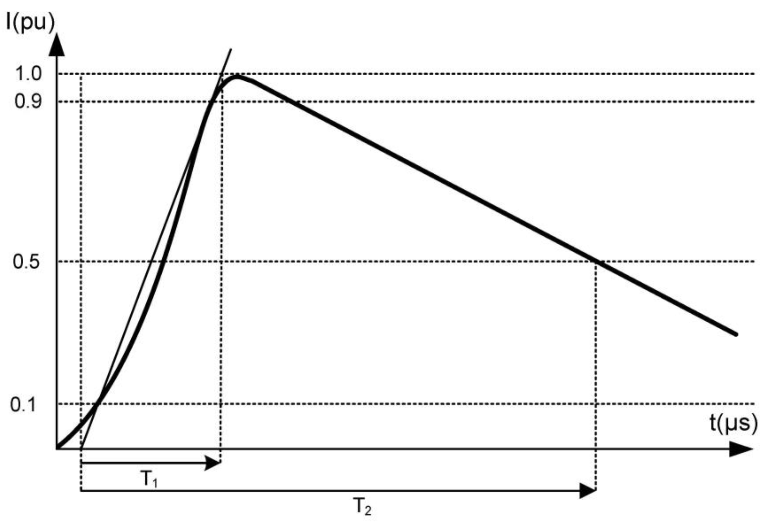
The lightning waveform as per Figure 1 is characterized by a rise time T1 which corresponds to the time till peak current and decay time T2 which is the time till the current gets 50% of its peak value.
Once a lightning protection system is designed and tested according to these parameters, its compliance with IEC61400-24 LPL I is ensured, meaning that the wind turbine is designed to be protected against 98% of lightning strikes. Depending on the project specific location, and despite designing the wind turbine lightning protection system to the upper limits of the standards, there are cases that this can cause it to fall within the other 2% of cases. According to the wind turbine design standard, IEC61400, specific requirements are applicable in order for the product to be compliant with it. Regarding lightning protection, the wind turbine should be compliant with IEC61400-24 [1], and the corresponding standards IEC62305-1-4 [4,5,6,7,8], while protection against electromagnetic impulses according to Std. IEC61312-1 [9] should be ensured. The earthing system of the wind turbine should have double the capabilities to allow the reliable operation of the electrical installation according to IEC60364-6 [10] and EN 50522 [11] standards provisions, acting as the earthing system of the wind turbine lightning protection system (LPS). Furthermore, wind turbine LPS should ensure the protection of major components and the safety of living beings inside and outside the wind turbine, including its area of installation (installation pad).
2.2. Lightning Protection Design Principles
The wind turbine LPS consists of three main parts, the external protection system, the internal part, and the earthing system. The external system protects against lightning strokes, the parts of the wind turbines that can be hit directly by lightning such as the blades, nacelle, and tower, while internal protection consists of the parts that carry the lightning current and protect the major components inside the wind turbine such as the generator, transformer, and electronic devices. The earthing system is the last part of the LPS and it dissipates the remaining lightning current and ensures that the step and touch voltages are within the acceptable limits, as these are defined by international standards [12,13,14]. External protection is considered to be the lightning protection of the blade, provided by the receptors and a down conductor, and internal protection is provided by the surge protection devices (SPD), cable shielding, and equipotential bonding. In regards to the earthing system, a low impedance is desirable since it reduces the step and touch potentials and reduces the voltages along the tower.
2.2.1. External Lightning Protection System of Wind Turbine
The external LPS aims to protect the wind turbine’s exposed components from damage in case of a lightning stroke. The components that to be protected are the blades, the nacelle, and its external components (anemometer, coolers, and aviation lights) and the tower. The blade, and especially the tip, is the highest point of the wind turbines, and thus, it is the most vulnerable one during thunderstorms. The lightning protection of the blade is one of the key factors to mitigate the risk of damage or even failures of the whole wind turbine. Once a lightning current hits the blade, this must be transferred in the most efficient way inside the nacelle via jumpers or spark gaps and to the tower down to the earthing system. The tower itself is used as the main down conductor, and for that purpose, the tower sections are either spray galvanized [15] or electrically connected via earthing jumpers, and finally, with the wind turbine main bonding bar, which acts as a interface between the wind turbine external and internal LPS and the earthing system.
2.2.2. Internal Lightning Protection System of Wind Turbine
Wind turbines, especially the ones of the last decade, are equipped with several electronic components and devices, with the main ones being the central controller and the power converter. These and other electrical and electronic devices are galvanically isolated and located in earthed metal housings and cabinets that are equipotentially connected to the nacelle internal equipotential bonding system. During the occurrence of a lightning strike or any overvoltage event (surge), the installed nacelle surge protection devices should ensure that the lightning energy can be absorbed, with minimum risk for the critical electrical and electronic components.
2.2.3. Wind Turbine Foundation Earthing Electrode
The wind turbine foundation earthing electrode or wind turbine earthing system is burdened with the primary task to protect lives and the property in the event of electrical faults (short circuits, earth faults, etc.) and during transient phenomena, such lightning strokes and switching operations. The earthing system should provide a low resistance path for the fault current to ensure the protection of the equipment and personnel. Regarding LPS operation, it provides a discharge path for the surge arrestors and the lightning current that has passed through the external and internal LPS. It should be also designed in such way to minimize the ground potential rise, and thus, the presence of dangerous touch and step voltages.
2.3. Motivation and Challenges
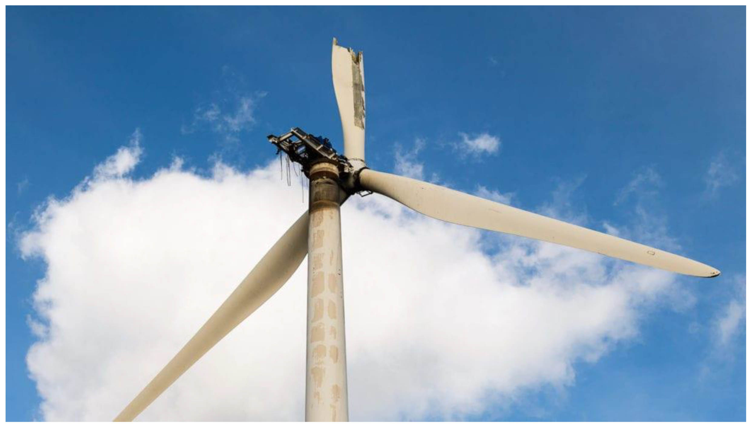
The combination of the rapid increase in wind energy and the continuous development of the products (bigger rotors, higher hub height, and larger nacelles), including their exposure mainly to medium-to-high-density lightning storms, makes the development of wind turbine lightning protection necessary, ensuring safety, reliability, robustness, and as aforementioned, easy adaptation to local or project-specific conditions. Furthermore, the nature of lightning is based on its probability of hitting a wind turbine, especially in the case of a cluster of turbines. It should be also understood that the LPS cannot prevent the potential stroke from hitting the wind turbine, but it reduces the impact and damage that can be caused due to lightning strokes and strokes close to the wind turbine. The impact of lightning on a wind turbine can be severe such as the one in Figure 2. In such cases, their operation is continued till a total failure occurs, since the safety systems cannot react. In milder damage scenarios, the wind turbine continues its operation, but with an impact on the power curve profile, which causes significant energy losses. The industry focuses on the reasonably fast and smooth construction and reliable operation of projects throughout their lifetime with the maximum possibility of ensuring that the investing stakeholders break even and that profits that be made. In the current work, we present a modular lightning protection methodology that utilizes the experience gained from the operation of wind farms in several locations, in variable soil conditions, and in areas from low to high lightning densities. The aim of this article is to propose a modular lighting protection that is easy adaptive, cost efficient, and ensures the needed level of protection for a specific location in which a wind turbine or a wind farm is located.
3. Methodology
Wind turbines have been analyzed and are vulnerable to lightning strikes, and their reliable operation is challenged due to this. Furthermore, the increasing number of wind installations and fast project execution mean that lightning protection solutions that can be applied to most projects in specific ways are needed. In this section, we present a methodology that focuses on modular lightning protection that could be applied on a project-specific basis, which produces a low operational risk of lightning and reduces the hazards to a tolerable level [1]. Lightning protection systems for wind turbines are based on the International Electrotechnical Commission (IEC) IEC 61400-24 standard. According to this standard, the lightning protection levels (LPLs) are set in accordance with the probability of minimum and maximum expected lightning currents, from I to IV. In LPL I protection, the expected peak current can range from 3 kA to 200 kA, with a probability that 99% of strikes will be lower than 200 kA and 99% of strikes will be higher than 3 kA [17]. The parameters for LPL II and III–IV reduce the values of LPL I by 98% and 95%, respectively. This methodology focuses on the lightning protection improvement, independent of the blade mechanical design and material. This methodology is based on a Greek lightning experience, since the topography is such that it includes almost all types of terrains, flat or low-attitude ones and complex ones (high-altitude, steep hills). This methodology could be applicable globally in order to mitigate the risks during the construction and operation of wind turbines in areas with specific lightning characteristics.
3.1. Classification of Sites Based on Lightning Density
The ground flash density is an important parameter in lightning protection because the risk evaluation of the lightning protection procedures is based on this [18]. The lightning density of an area is a critical metric to assess the overall risk since this includes the safety risk during construction and operation and the financial risk caused by damage (to the blade tip, along the blade, and to the nacelle components) due to lightning. Hereto, we introduce four site classes of ground flash density with the following characteristics:
- Low: with equal or less than 4 strikes/km2/year;
- Medium: within the range 4 < strikes/km2/year < 8;
- High: within the range 8 < strikes/km2/year < 10;
- Ultra-High: with more than 10 strikes/km2/year.
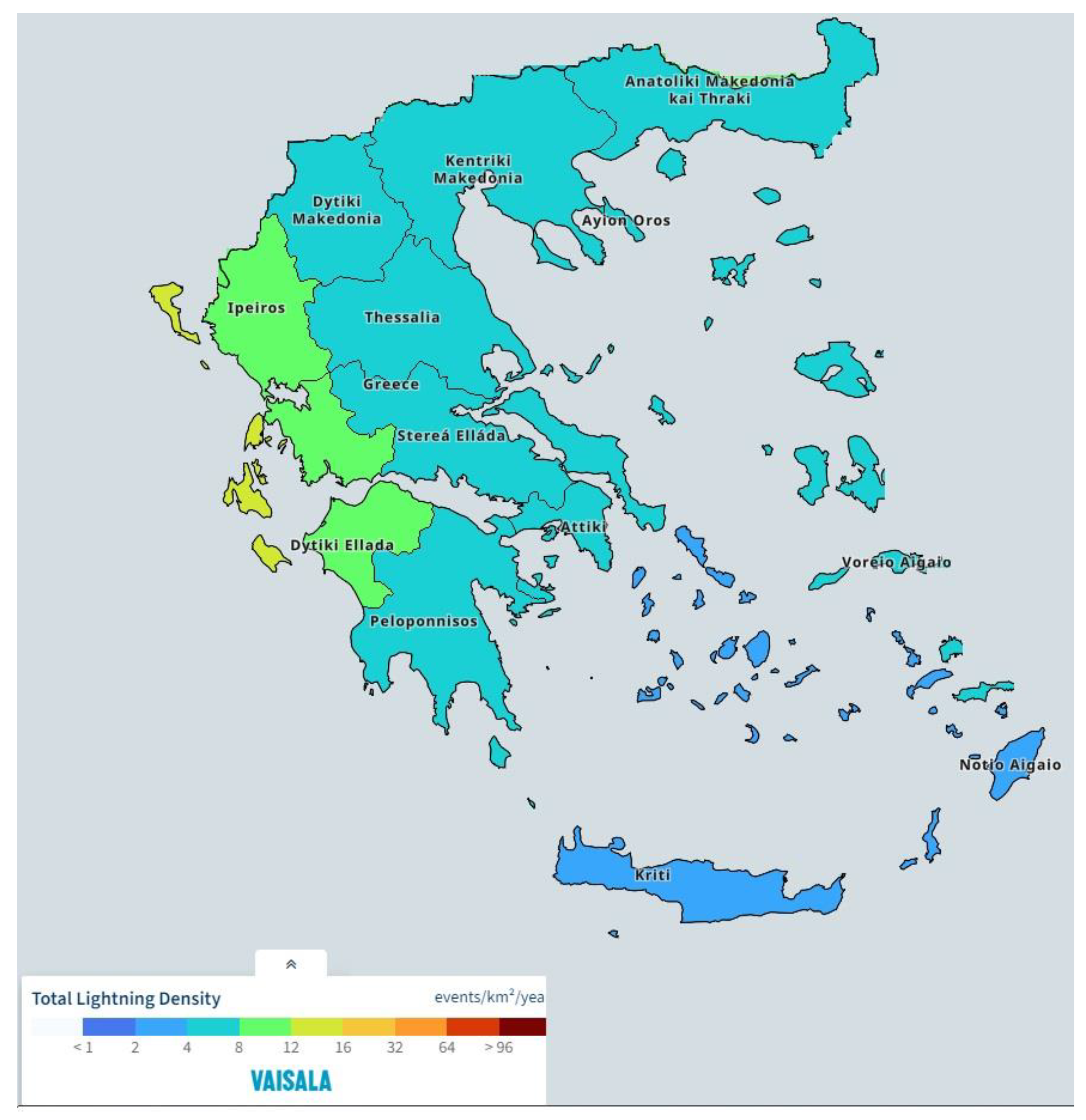
The classification proposed above is one part of the methodology proposed by the authors based on the number of thunderstorm days per year and reported incidents from a local database [19] or other resources and the lightning map (Greek isokeraunic map) as per [20] and is based on the findings from the Global Lightning Density Map [21]. The below areas refer to mainland of Greece, excluding islands. Lightning ground density is based on the thunderstorm days (T) in the areas in which the wind farms are located, based on Figure 3, and was calculated based on [22,23] Formula (1):
NG1 = 0.04 × T1.25
The lightning ground density is also calculated with the formula introduced in Annex A.1 of IEC Std. IEC62305-2 [4] according to Formula (2):
NG2 = 0.1 × T
Formulas (3) and (4) which are based on [1,2,24,25] and are used for the estimation of the effect of flashes with multiple ground strike points and the annual number of dangerous events for a wind turbine:
NSG = 2 NG
ND = NSG × 9π × H2 × 10−6
The results of Table 3 show that western and northern areas of Greece have a high lightning density aligned with Figure 4 ranges, and thus, the wind turbines have higher lightning risks compared with those in the rest of the areas. The calculated average number of dangerous events that may create a risk of damage or even failure of the wind turbines with a total height of 125 m is in Table 4.
3.2. Classification of Sites Based on Soil Resistivity
The earthing system of a wind turbine has a crucial role, ensuring protection against electrical faults, keeping the step and touch voltage within the safety limits for living beings, and it functions as a dissipation area for the lightning and electrical currents that are attenuating there. The earthing system design is related to the soil conditions, and thus, to resistivity. International reference standards IEC60364-6 [9], EN 50522-2022 [10], IEEE Std. 81-2012 [11], and IEEE Std. 80-2013 [12] should be consulted for the design, construction, and verification of an earthing system, and the wind turbine should meet the minimum requirements of IEC61400-24 [1]. The IEEE Std. 80-2013 [12] and the IEC60479-1:2010 [13] define the method for the calculation of the step and touch voltages.
In the Greek territory, a large majority of the wind farms have been installed in mountainous areas with rocky ground, which consequently leads to high soil resistivity values and ground resistance. These areas require additional measures in order to reduce the impact of the soil and to ensure a safe working environment, while keeping the plant costs at a level that does not affect the project business case. According to the findings in [26], the reported ground resistance values of wind turbines in the Greek territory are in the range of 1 Ω to 150 Ω, with 32% of the cases being within the 10 Ω boundary, with gross of the values being up to 70 Ω and some minor cases being up to 150 Ω. These values consequently demonstrate the high soil resistivity conditions. In the current article, we introduce soil resistivity classes that will be utilized for the modular lightning protection of the wind turbines and are summarized in Table 5.
3.3. Classification of Sites Based on Altitude
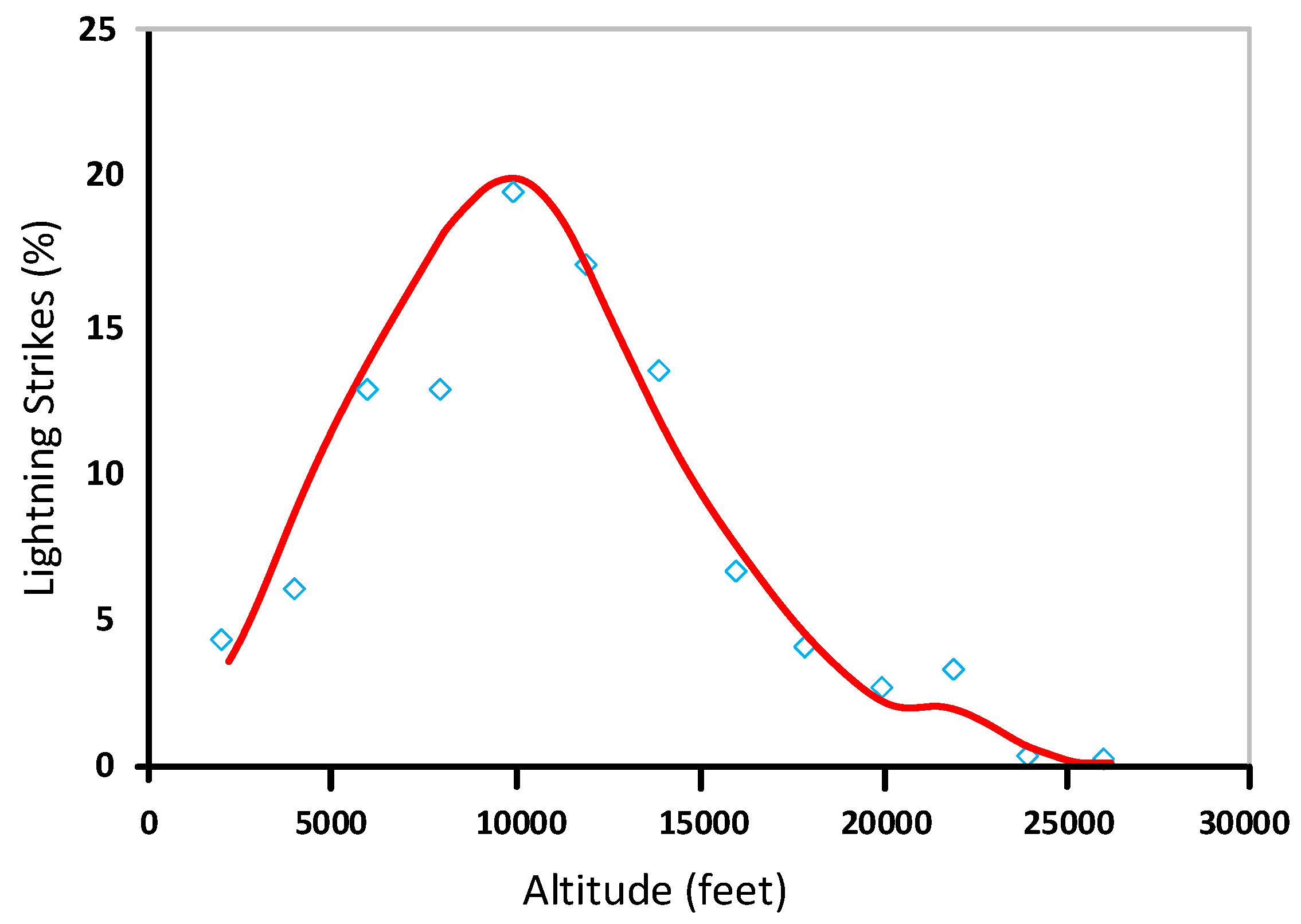
Even though the number of studies evaluating the relationship between the topography characteristics and lightning activity is limited, it seems that during spring and summer, there is a positive relationship between lightning activity and elevation, while this feature is not evident during the other periods of the year [27]. According to [28], at the low or high altitudes, the authors noticed a fluctuation in lightning re-occurrence, while at medium altitudes, the number of lightning events increases with the elevation. With the elevation of the area, the proportion of the normal lightning flashes against the total lightning flashes increases gradually with the altitude, with a peak at 10,000 feet, as per Figure 5. Lightning density was found to be increased at altitudes ranging from 500 to 2000 m in Austria, as per [29]. Besides site elevation, terrain slope has a stronger impact on lightning activity, since a steep topographic gradient may produce deep convection, which is directly related to the production of lightning [30]. The lightning risk is thus affected, apart from elevation, by slope steepness. Lightning activity enhancement is related, apart from elevation, to the slope of the terrain. The slope of the terrain enhances the cloud-to-ground (CG) lightning activity during winter and autumn in the eastern Mediterranean region [31], and this is considered in the current methodology. The terrain slope increases the lightning density, which is stronger factor than elevation is [32]. In Table 6, we introduce a classification of wind farm sites based on the elevation above sea level (a.s.l.).
4. Basic Lightning Protection and Add-Ons
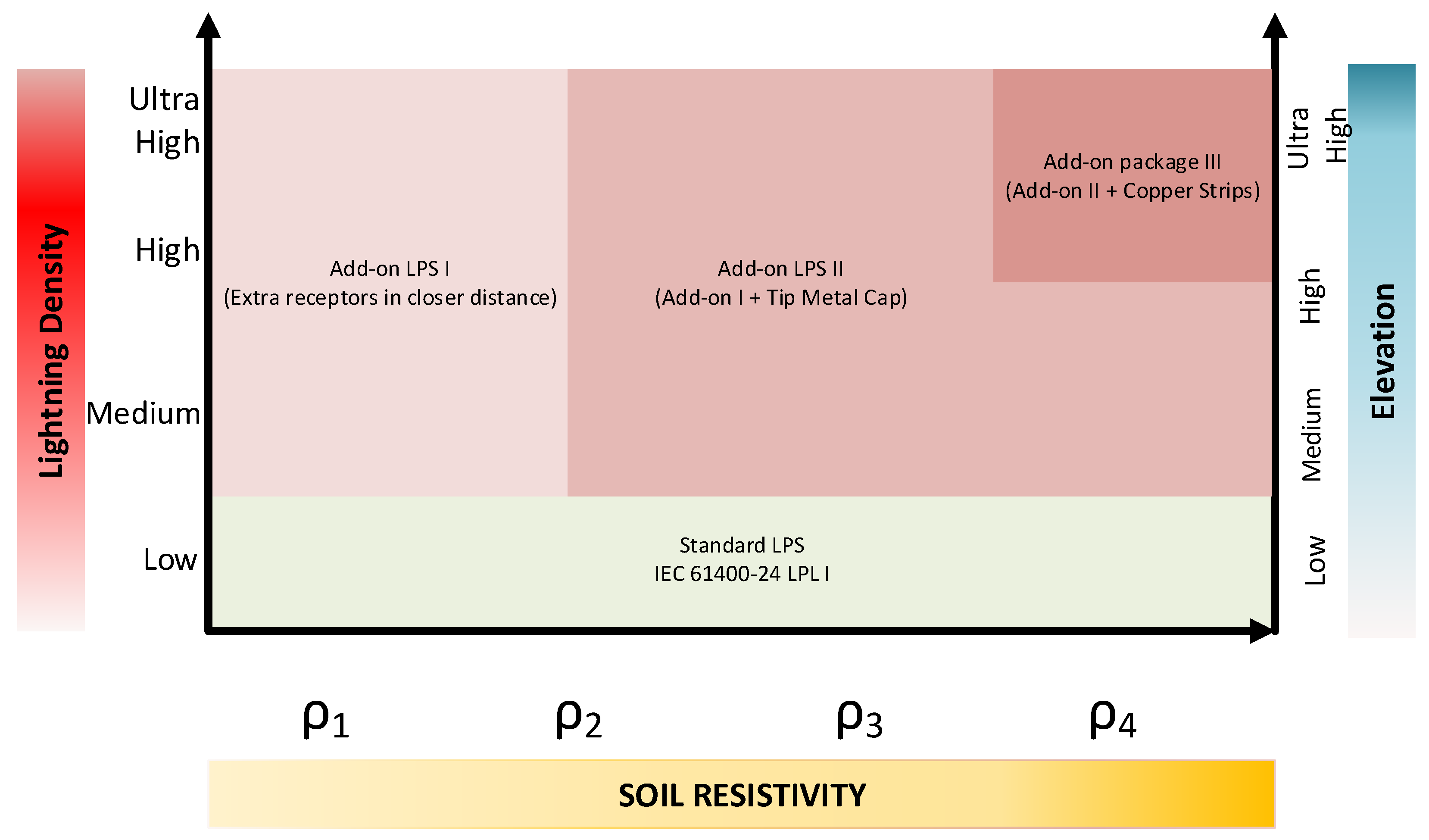
Section 3 hereto introduces three specific parameters that affect the performance of a lightning protection system of a structure, and specifically, a wind turbine. Once the wind turbine lightning protection system is designed according to the provisions of IEC61400-24 and the other IEC and IEEE standards, it ensures an efficiency of 98%, however, there are specific sites with microclimate conditions that create challenges. Furthermore, a lightning system should combine three major technical aspects: (i) the safe, reliable operation of the wind turbine, (ii) cost efficiency, and (iii) the meeting of site-specific conditions. Safe and reliable operation are crucial for an LPS since they are considered as design rules that need to be respected in order to secure the safety of living beings and the high availability of the wind turbine in order ensure the return of investments. LPS, in principle, should not introduce additional manufacturing costs or costs during operations, contributing to a healthy business, but it should be adaptive, meaning that it possibly can be tailored to the site-specific conditions. The concept that is introduced here is the modular lightning protection system for a wind turbine, which uses the IEC61400-24 provisions for LPL-I as a basis and should be adaptive to the site-specific conditions. This LPS can be introduced to the design of a wind farm or during its operation. The LPS should be modular, meaning that it should have a basic standard design, and depending on the conditions, it should have pre-designed and available add-on options. The standard design of the wind turbine LPS should include the following:
- A lightning protection zone-based blade (LPZ0A and LPZ0B), which splits the blade into four areas, in compliance with IEC61400-24;
- Lightning receptors that are equally distributed along the blade, connected with a conductor of 50 mm2 to the blade root;
- Externally mounted nacelle components with lightning protection by means of collector system (anemometer lightning rod, etc.);
- Nacelle components that are equipotential bonded via 50 mm2 cable and connection to the blade LPS;
- A lightning protection zone (LPZ1 and 2) by means of surge protection devices (SPD) for the critical components including generator terminals, a transformer MV side, converter output terminals, and a tower controller;
- A tower to be utilized as a down conductor, and between its sections, are the earthing jumpers to ensure continuity, and at the bottom of the tower, it is connected to a wind turbine bonding bar. Any components that are present around the bonding bar should be connected there;
- A wind turbine bonding bar (WTBB) that acts as the interface between the wind turbine internal earthing system and the external one.
A wind turbine that is built during a project can include either a standard LPS or a site-specific one, which is a modular LPS, taking the chart introduced in Figure 6 as the basis. This figure combines the three major factors that are related to the efficiency of a wind turbine LPS, which can be all considered either in combination or even on their own, and we can then select the one that leads to the safest result, provided that the business allows this or the risk is one that an investor can undertake. The basic design should incorporate the IEC61400-24 provisions, necessitating in the placement of receptors at a specific distance away from the blade inside that is connected to a down conductor of a proper size (min. 50 mm2), which can be adapted further.
5. Proposed Lightning Protection
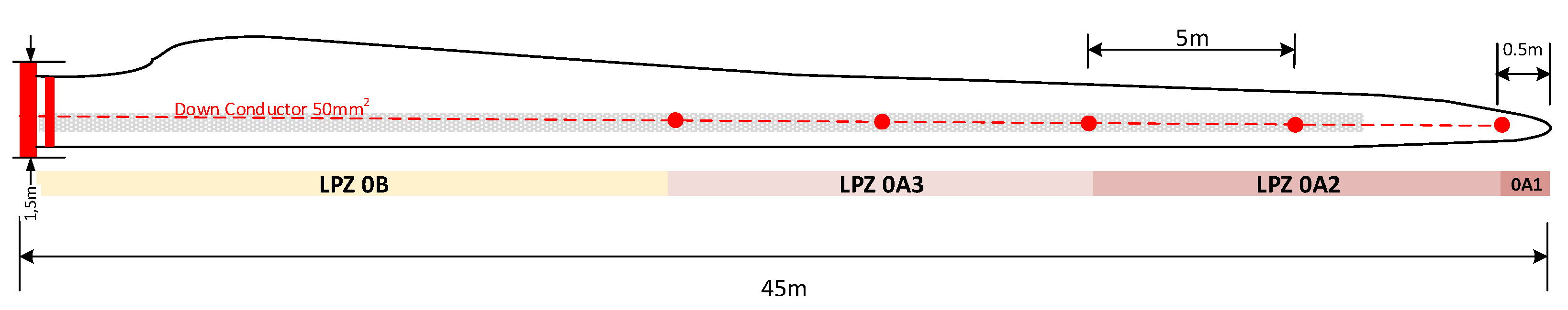
The current lightning protection system of wind turbines is a proposal that utilizes the aforementioned methodology with basic protection that is compatible with the IEC61400-24 provisions and add-ons that achieve safe and reliable protection that is adapted to the area-specific conditions. This system ensures the presence of a basic and standard design with the highest protection level based on IEC61400-24, achieving a predefined cost that can then be further improved to meet the local lightning conditions. The basic lightning protection system consists of either lightning receptors placed along the blade length or lightning conductors placed on the blade surface or inside the blade. The main aim of this system is to divert the lightning current from the attachment point to the nacelle in such way that any arcs inside the blade or between the blade root and hub is avoided. The specific LPS is based on a blade of 45 m in length, type D, as per [1], and the tip height is ~125 m higher than the wind turbine installation altitude is. The site altitude is around 900 m asl. The blade is made of fiberglass (GRP), allowing it to withstand the mechanical load and it has a lighter weight. The blade is split into two shells wrapped around a balancing support beam. The blade should have such a design that allows it to be aerodynamically efficient at capturing as much as kinetic energy from the wind as possible. To protect the blade from lightning discharges, discrete air terminations have been installed according to IEC TR 61400-24 [1]. These receptors are installed on both sides of the blade from a radius of 20 m to the tip region, with a spacing of 5 m, totaling five receptors on each side. The receptors are connected to an inner down conductor, a 50 mm2 copper conductor fixed to the beam with mechanical joints. At the root end of the blade, the specific down conductor is connected to the flange, which acts as the electrical interface for the rest of the turbine. The blade design is shown in Figure 7 based on concept A, as per IEC Std. 61400-24:2019, where the blade is split into two basic lightning protection zones with LPZ0A, for it to be split further into three zones. The lightning receptors are placed at a distance of 5 m away from each other, covering half of the blade length, with the first one positioned 50 cm away from tip. LPZ-0A1 is the one that is most exposed to the lightning zone, where high-amplitude lightning is expected to hit with a peak current of up to 200 kA (10/350 μs waveform). LPZ-0A2 is a zone where a current of less than 200 kA (usually the half of peak value) is expected, while LPZ-0A3 is a zone where no direct lightning strike is expected, but still, an induced current can be present in the outer zones with a maximum amplitude of 10 kA. LPZ-0B is a zone in which no direct lightning is expected to hit, but the current from the outer zones is considered as an indirect effect. The standard blade design fulfils the IEC61400-24 provisions, with 98% reliability of it covering most of the cases globally. This percentage means that 98% of all lightning strikes will only cause damage that is acceptable until the next scheduled maintenance and has no influence on the performance of the wind turbine. The wear of some components must be expected over the years (e.g., the receptors in the blades, etc.).
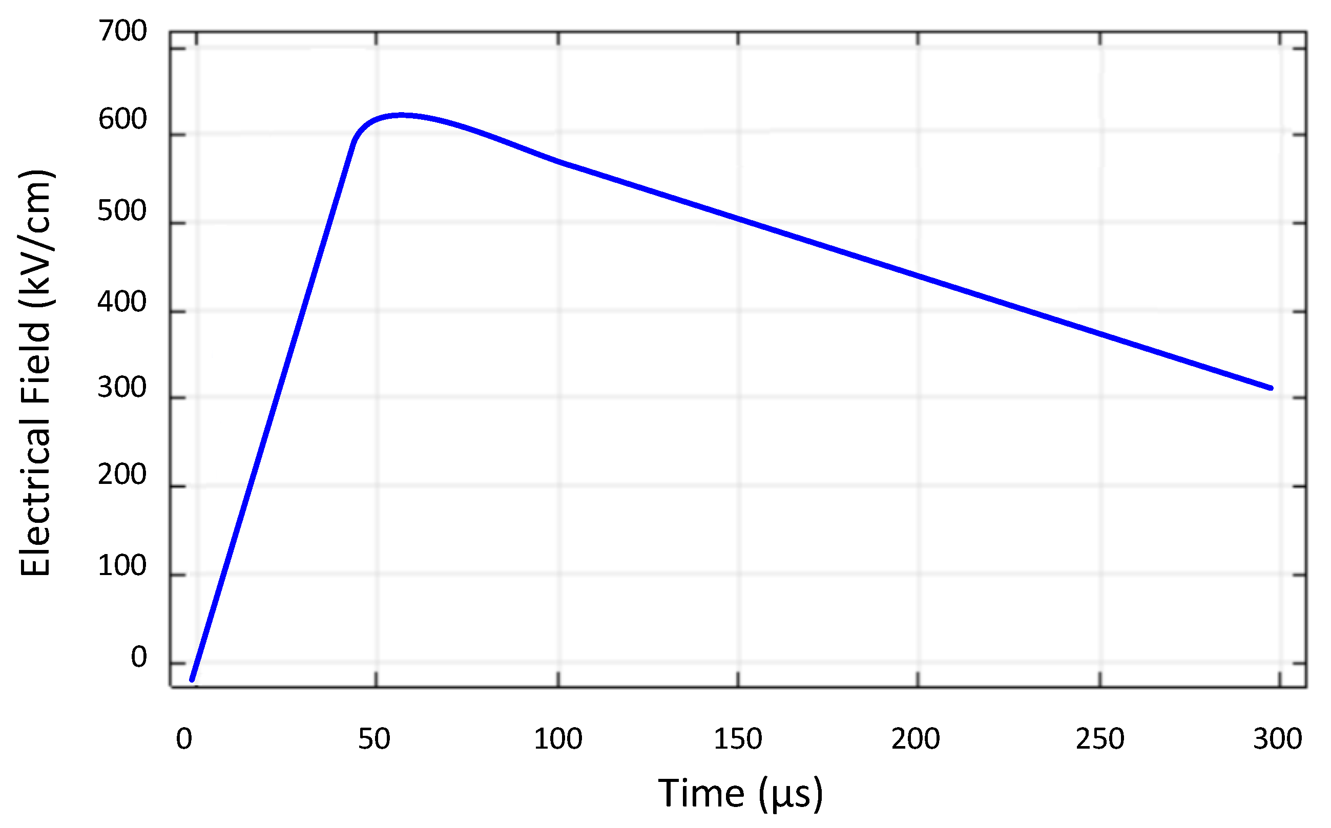
Due to the uncertain nature of lightning, which is related to the ambient conditions and site topography, there are several cases, 2% or even fewer, of lightning strikes that wind turbines are exposed to, where the IEC61400-24 design is not sufficient, causing mild damage and, in some cases, even catastrophic damage to the blade and even to the whole wind turbine. The solution that is suggested here is the installation of add-on lightning protection components to protect the most vulnerable component of the wind turbine, the blade. The blade performance was simulated in the FEM platform, and in Figure 8, the electrical field that is induced in the blade based on the standard LPS design is demonstrated. This electric field in the initial phase of lightning can ionize the area around the attachment point, and once the lightning attaches to these places, initially, the material is partially available for current and heat dissipation until the current has been distributed across the entire cross-section or area, which can cause unforeseen damage.
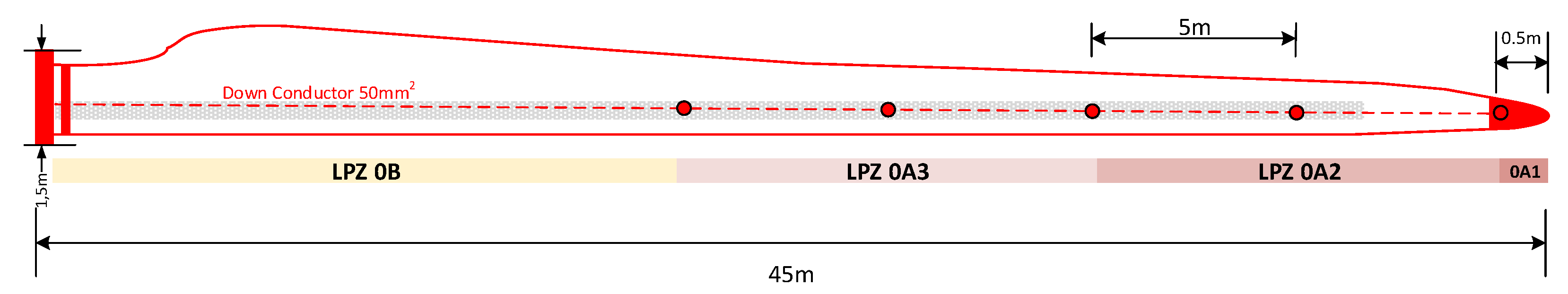
In Figure 9, we included lightning protection along the leading and trailing edge of the blade plus metal tip protection, which is a metal cover copper or stainless steel made for mechanical protection purposes. The copper strip installed around the blade on both sides is 40 mm × 3 mm, with a less aerodynamic impact.
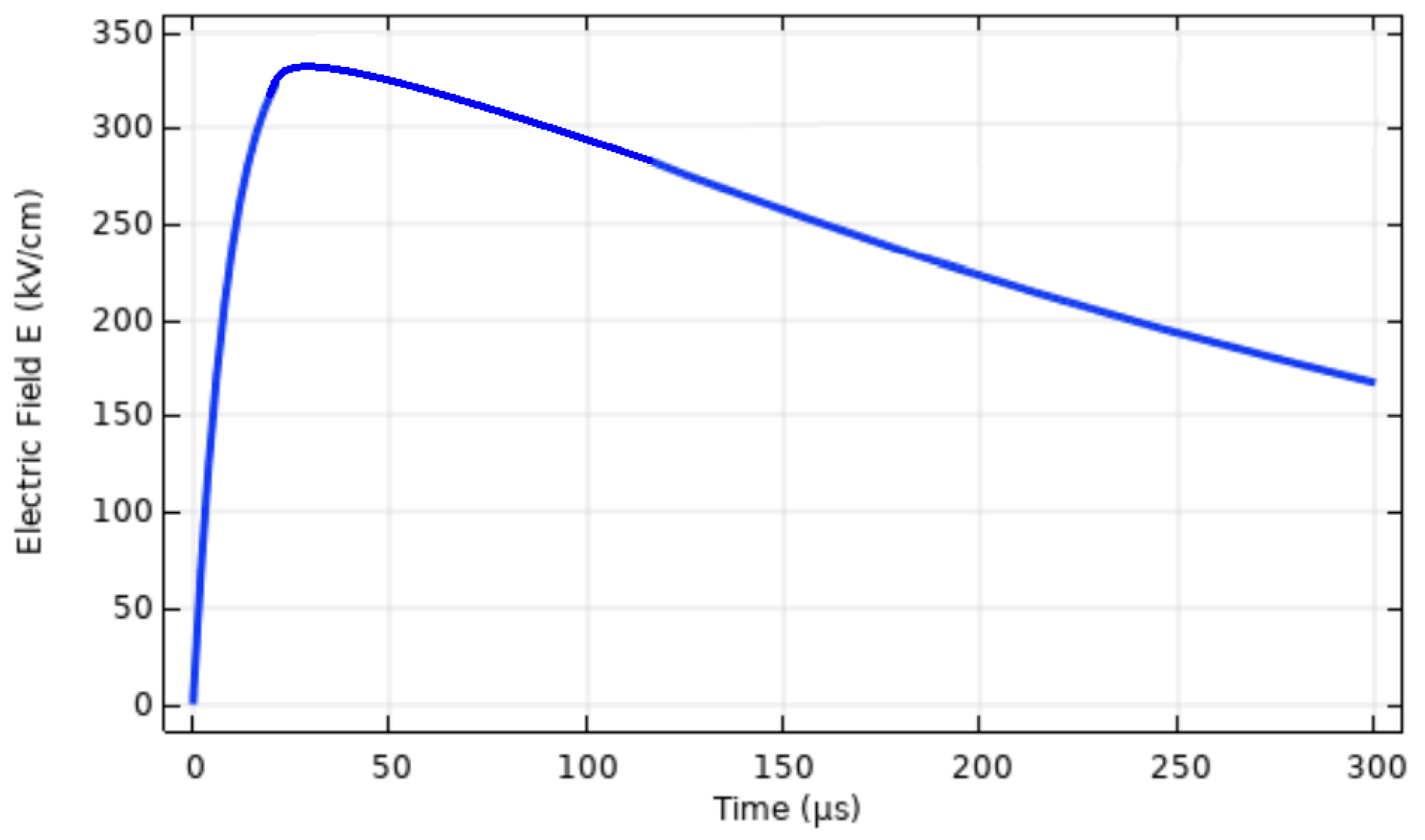
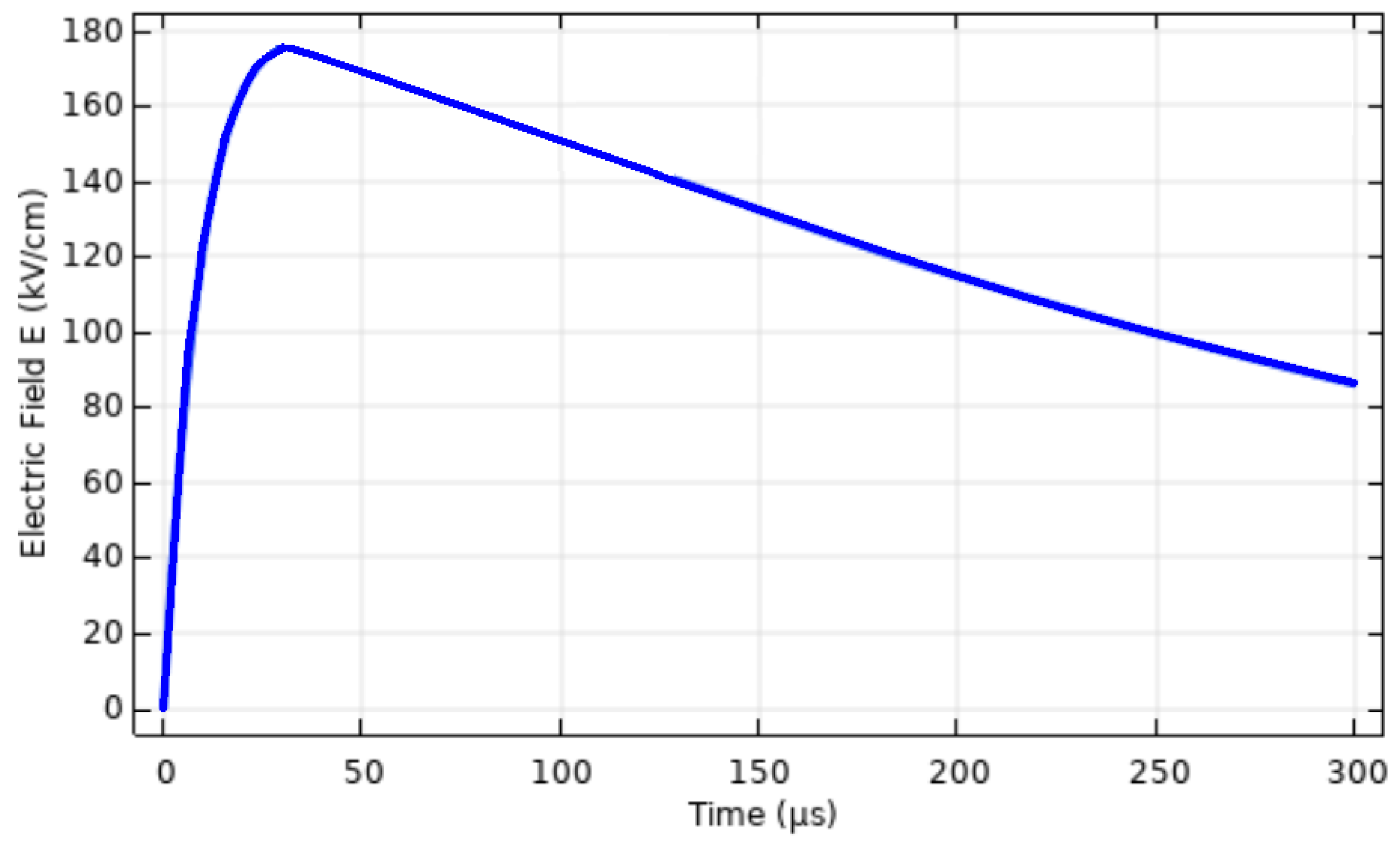
In Figure 10, we present the result extracted from the FEM platform simulations of the effect of the electrical field on the copper strip by applying a lightning impulse of 200 kA, with a profile of 10/350 μs due to its higher capacity for energy and transfer charge (Q) rather than with 1.2/50 μs, resulting in more exposure of the equipment to the lightning consequences. In Figure 11, we present the effect of the electrical field on the blade material GFP.
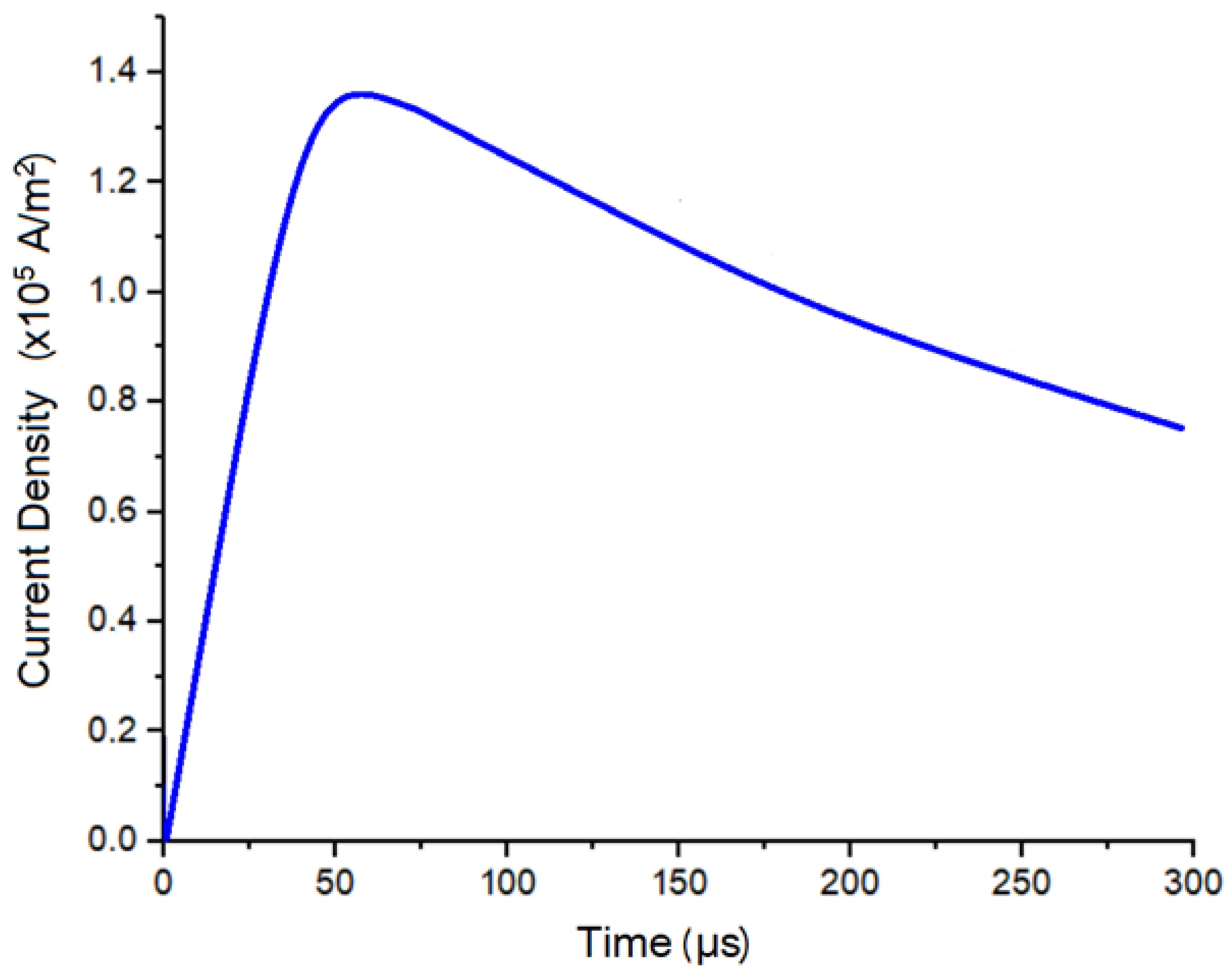
In Figure 12, we demonstrate the current density in the 40 mm × 3 mm copper strip, which reaches a peak value of 1.35 × 10⁵ A/m2 in 50 μs (Τ1) after the event and a 50% value of 0.7 × 10⁵ A/m2 in 300 μs (Τ2) triggered by a 10/350 μs surge waveform.
The results of the simulations regarding the specific design are summarized in Table 7 hereto, and these were extracted from the software probes placed on the strip and on the blade surface.
The results in Table 7 show that the simulation results of the electrical field, the maximum current density, and the maximum temperature are below the design’s considered limits, and the proposed solution can provide the highest level of protection in site-specific conditions. This LPS can be used under specific conditions based on methodology mentioned in Section 3 hereto.
6. Conclusions
A blade can receive around 20 strikes on an annual basis in cases of high-density sites and less than 7 in low- or medium-density sites. These numbers can be affected largely by the geographical location of the wind farm and can be considered as a rule of thumb from the field experience and operation of wind farms worldwide. The risk of lightning striking turbines was not understood in the past, which led to an underestimation of how many events a turbine will experience because the risk assessment was not based on the lightning environment before the turbine was erected. Wind turbines are exposed to lightning due to their tall height, which can even exceed 200 m above ground level. It is of high importance to ensure that these structures are protected against lightnings during their lifetime for business purposes in order to ensure a good operational availability and a solid income for the owner. Apart from this, the safety of living beings is the first priority, especially for personnel working inside or around the wind turbine [36,37]. In the current work, we present a methodology that acts as a roadmap to be considered in order to obtain a basic, but still reliable LPS (base design), but as it is modular, it provides the opportunity to install add-ons based on the site-specific conditions for enhanced lightning protection. Ideally, a modularized LPS should allow retrofitting in the field in case conditions that demand increased protection. The solution presented here to achieves reliable, modular, and enhanced protection, which could be further optimized based on the experience that is gained from the conditions onsite. The soil conditions were considered, such as 10 ohms of ground resistance, but the solution was focused on the most exposed and vulnerable part, which is the blade. Once the blade is protected and the WTG IEC61400-24 provisions are followed, the high-level risks are mitigated, minimizing the probability of failures. LPS design is not a standalone task, but rather, it includes the aerodynamic design of the blade, and both should be considered in order to ensure the mechanical protection of the structure, apart from transient voltage risks inside the nacelle and tower [38]. The content of the current paper can act as a reliable lightning protection selection guide for those in the industry, which can be validated or to be adapted to meet specific needs with a site-specific analysis or during the operation of the wind turbines.
Author Contributions
All authors have contributed equally. All authors have read and agreed to the published version of the manuscript.
Funding
This research received no external funding.
Institutional Review Board Statement
Not applicable.
Informed Consent Statement
Not applicable.
Data Availability Statement
No new data were created or analyzed in this study. Data sharing is not applicable to this article.
Conflicts of Interest
The authors declare no conflict of interest.
References
- IEC61400-24; Wind Energy Generation Systems—Part 24: Lightning Protection. IEC: Geneva, Switzerland, 2019.
- Favro, L.D.; Thomas, R.L.; Han, X. State of the art of thermal wave imaging for NDE of aging aircraft. Tech. Aging Infrastruct. Manuf. Int. Soc. Opt. Photonics 1999, 3586, 94–97. [Google Scholar] [CrossRef]
- Lightning Strike Blade Damages Push Vestas into Fresh Quarterly Loss. Available online: https://www.rechargenews.com/wind/lightning-strike-blade-damages-push-vestas-into-fresh-quarterly-loss/2-1-855590 (accessed on 11 November 2022).
- IEC62305-1; Protection against Lightning—Part 1: General Principles. IEC: Geneva, Switzerland, 2011.
- World Meteorological Organization. Electromagnetic Methods of Lightning Detection. Available online: https://library.wmo.int/doc_num.php?explnum_id=3184 (accessed on 23 December 2022).
- IEC62305-2; Protection against Lightning—Part 2: Risk Management. IEC: Geneva, Switzerland, 2012.
- IEC62305-3; Protection against Lightning—Part 3: Physical Damage to Structures and Life Hazard. IEC: Geneva, Switzerland, 2011.
- IEC62305-4; Protection against Lightning—Part 4: Electrical and Electronic Systems within Structures. IEC: Geneva, Switzerland, 2011.
- IEC 62313:2009; ED1 Railway Applications—Power Supply and Rolling Stock—Technical Criteria for the Coordination between Power Supply (Substation) and Rolling Stock. IEC: Geneva, Switzerland, 2019.
- IEC 60364-6; Low Voltage Electrical Installations—Part 6: Verification. IEC: Geneva, Switzerland, 2011.
- EN 50522; Earthing of Power Installations Exceeding 1 kV AC. Cenelec: Brusseles, Belgium, 2022.
- IEEE 81-2012; IEEE Guide for Measuring Earth Resistivity, Ground Impedance, and Earth Surface Potentials of a Grounding System. IEEE: New York, NY, USA, 2012.
- IEEE 80-2013; IEEE Guide for Safety in AC Substation Grounding. IEEE: New York, NY, USA, 2012.
- IEC 60479-1:2018; Effects of Current on Human Beings and Livestock—Part 1: General Aspects. IEC: Geneva, Switzerland, 2018.
- Fellensiek, A.; Bohm, A. Earth and Lightning Protection System for Enercon Wecs; Technical Document; Enercon: Aurich, Germany, 2007. [Google Scholar]
- Wind Turbine Blade Dielectric: What You Need to Know. Available online: https://weatherguardlightning.com/wind-turbine-blade-dielectric-strength/ (accessed on 3 December 2022).
- BS EN 62305-1:2011; Technical Committee GEL/81. Protection against Lightning Part 1: General Principles. The British Standards Institution: London, UK, 2017.
- Cooray, V. Lightning Protection; Power and Energy Series; IET: Hong Kong, China, 2018; ISBN 978-1-84919-106-7. [Google Scholar]
- The TALOS Project: Thunder and Lightning Observing System. Available online: https://www.meteo.gr/talos/index.cfm (accessed on 23 December 2022).
- Pastromas, S.; Pyrgioti, E. Protection Measures on Wind Turbines against Lightning Strikes. In Proceedings of the International Conference on Renewable Energies and Power Quality (ICREPQ’17), Malaga, Spain, 4–6 April 2017; pp. 388–393. [Google Scholar]
- Vaisala Xweather. Interactive Global Lightning Density Map. Available online: https://interactive-lightning-map.vaisala.com/ (accessed on 11 November 2022).
- Anderson, R.B.; Eriksson, A.J.; Kroninger, H.; Meal, D.V.; Smith, M.A. Lightning and Thunderstorm Parameters; International Conference on Lightning and Power Systems, Institute of Electrical and Electronic Engineers: London, UK, 1984. [Google Scholar]
- Grant, I.S.; Anderson, J.G.; Hileman, A.R.; Janischewskyj, W.; Lee, G.E.; Longo, V.J.; Chisholm, W.; Parrish, D.; Roukos, N.K.; Main, C.T.; et al. A Simplified Method for Estimating Lightning Performance of Transmission Lines. Ieee Trans. Power Appar. Syst. 1985, 104, 919–932. [Google Scholar]
- IEC 62858:2019; Lightning Density Based on Lightning Location Systems—General Principles, Edition 2.0. IEC: Geneva, Switzerland, 2019.
- Stéphane, P. Introduction to the IEC 62858: Lightning Density Based on Lightning Locating Systems; International Lightning Protection Symposium: Shenzhen, China, 2018. [Google Scholar]
- Androvitsaneas, V.P.; Damianaki, K.D.; Nicolopoulou, E.P.; Gonos, I.F. Statistical Analysis of Lightning Flashes over Wind Parks in Greece. Energies 2021, 14, 6076. [Google Scholar] [CrossRef]
- Kotroni, V.; Lagouvardos, K. Lightning occurrence in relation with elevation, terrain slope, Cand vegetation cover in the Mediterranean. J. Geophys. Res. 2008, 113, D21118. [Google Scholar] [CrossRef]
- Wu, M.; Sun, Z.; Tang, Q. The Variation of Lightning Current Parameters with Altitude in Shandong Region. IOP Conf. Ser. Earth Environ. Sci. 2020, 598, 012084. [Google Scholar] [CrossRef]
- Schulz, W.; Diendorfer, G. Lightning characteristics as a function of altitude evaluated from lightning location network data. In Proceedings of the International Conference on Lightning and Static Electricity, Society of Automotive Engineers, Toulouse, France, 22 June 1999. [Google Scholar]
- Goswami, B.B.; Mukhopadhyay, P.; Mahanta, R.; Goswami, B.N. Multiscale interaction with topography and extreme rainfall events in the northeast Indian region. J. Geophys. Res. 2010, 115, D12114. [Google Scholar] [CrossRef] [Green Version]
- Galanaki, E.; Kotroni, V.; Lagouvardos, K.; Argiriou, A. A ten-year analysis of cloud-to-ground lightning activity over the Eastern Mediterranean region. Atmospheric Res. 2015, 166, 213–222. [Google Scholar] [CrossRef]
- Oulkar, S.; Siingh, D.; Saha, U.; Kamra, A.K. Distribution of lightning in relation to topography and vegetation cover over the dry and moist regions in the Himalayas. J. Earth Syst. Sci. 2019, 128, 180. [Google Scholar] [CrossRef] [Green Version]
- Kalair, A.; Abas, N.; Khan, N. Lightning interactions with humans and lifelines. J. Light. Res. 2013, 5, 11–28. [Google Scholar] [CrossRef]
- Bhanuprakash, L.; Varghese, S.; Singh, S.K. Glass Fibre Reinforced Epoxy Composites Modified with Graphene Nanofillers: Electrical Characterization. J. Nanomater. 2022, 2022, 4611251. [Google Scholar] [CrossRef]
- He, H.; Xia, D.; Luo, B.; Chen, W.; Bian, K.; Xiang, N. Simulation of positive streamer propagation in an air gap with a GFRP composite barrier. High Volt. 2021, 6, 1079–1091. [Google Scholar] [CrossRef]
- Glushakow, B.; Qin, H. Wind Turbine Lightning Protection of Blades, Electronics and Humans. In Proceedings of the 2019 International Symposium on Lightning Protection (XV SIPDA), Sao Paulo, Brazil, 30 September–4 October 2019; pp. 1–8. [Google Scholar] [CrossRef]
- Nasiri, M.J.; Homaee, O.; Najafi, A.; Jasinski, M.; Leonowicz, Z. Analyzing the Effect of Lightning Channel Impedance on the Induced Overvoltages in Wind Turbines. In Proceedings of the 2022 IEEE International Conference on Environment and Electrical Engineering and 2022 IEEE Industrial and Commercial Power Systems Europe (EEEIC / I&CPS Europe), Prague, Czech Republic, 28 June–1 July 2022; pp. 1–6. [Google Scholar] [CrossRef]
- Zhu, Z.; Jiang, M.; Crevenat, V. Simulation and Analysis of Surge Protection for Wind Turbines Based on ATP-EMTP. In Proceedings of the 2022 36th International Conference on Lightning Protection (ICLP), Cape Town, South Africa, 2–7 October 2022; pp. 155–159. [Google Scholar] [CrossRef]
Figure 1.
Rise time and time to half value schematic definitions [1].
Figure 1.
Rise time and time to half value schematic definitions [1].

Figure 2.
Severe wind turbine damage due to lightning [16].
Figure 2.
Severe wind turbine damage due to lightning [16].

Figure 3.
Isokeraunic map of Greece [20].
Figure 3.
Isokeraunic map of Greece [20].

Figure 4.
Lightning density map of Greece [21].
Figure 4.
Lightning density map of Greece [21].

Figure 5.
Lightning activity probability variation with altitude [33].
Figure 5.
Lightning activity probability variation with altitude [33].

Figure 6.
Lightning activity variation with altitude.

Figure 7.
Conceptual blade design including standard LPS.

Figure 8.
Electrical field on the standard LPS blade.

Figure 9.
Conceptual blade design including standard and add-on III LPS.

Figure 10.
Electrical field on standard and add-on III LPS copper strip.

Figure 11.
Electrical field on standard and add-on III LPS GRP.

Figure 12.
Conceptual blade design including standard and add-on LPS–GRP.


Table 1.
Physical effect of the lightning parameters and design adaptations of LPS to mitigate the effects [1,4].
| Lightning Parameter | Physical Effect | Design Concern |
|---|---|---|
| Peak current (kA) | Mechanical forces; | Mechanical mounting of cables |
| Voltage rise | and of connections | |
| Specific energy (MJ/Ω) | Thermal heating effect | Conductor cross-section; |
| Melting of supporting materials; | ||
| Heating of nearby equipment | ||
| Total charge (Coulomb) | Surface erosion | Blade engineering |
| Material melting | (aerodynamics, collector system, receptor position, etc.) | |
| Current rise steepness (di/dt) | Voltage rise; | Insulation selection; |
| Joints/coupling of components | Cable shielding | |
| Annual number of strokes | Phenomenon reoccurrence | Wind turbine or components’ lifetime |
Table 2.
Classification of lightning stroke types and characteristics [1].
Table 2.
Classification of lightning stroke types and characteristics [1].
| First Positive Stroke | Subsequent Stroke | Long Duration Stroke |
|---|---|---|
| 10/350 μs (rise time/time to half value *) | 0.25/100 μs (rise time/time to half value) | DC current with duration ≤500 ms |
| Ipeak 200 kA | Ipeak 50 kA | |
| Max. stroke charge 100 Cb (or As) | Max. stroke charge 200 Cb (or As) | |
| W/R = 10 MJ/Ω | Average steepness 200 kA/μs | |
| Frequency range [5] 900 Hz–32 kHz | Frequency range [5] 3.2 kHz–1.3 MHz | |
| Magnetic field of first stroke 25 kHz | Magnetic field of subseq. stroke 1 MHz | Magnetic field of long duration stroke; Low frequency |
* Definition of rise time (Τ1) and time to half value (Τ2) is provided in Figure 1 hereto.
Table 3.
Calculation of lightning density and classification.
| WPP Area | Annual Thunderstorm Days | Site Density (NG1/NG2) | Classification |
|---|---|---|---|
| Eastern Greece | 45 d/y | 4.7/4.5 flashes/km2/year | Medium |
| Central Greece | 52 d/y | 5.6/5.2 flashes/km2/year | Medium |
| Northern Greece | 73 d/y | 8.5/7.3 flashes/km2/year | High |
| South Greece | 22 d/y | 1.9/2.2 flashes/km2/year | Low |
| Western Greece & Ionian Sea | 84 d/y | 10.2/8.4 flashes/km2/year | High |
Table 4.
Calculation of lightning ground strike point and average annual dangerous events.
| WPP Area | Ground Strike Point Density (NSG1/NSG2) | Annual Dangerous Events (ND1) | Annual Dangerous Events (ND2) |
|---|---|---|---|
| Eastern Greece | 9.4/9.0 flashes/km2/year | 4.15 | 3.98 |
| Central Greece | 11.2/10.4 flashes/km2/year | 4.95 | 4.59 |
| Northern Greece | 17.0/14.6 flashes/km2/year | 7.51 | 6.45 |
| South Greece | 3.8/4.4 flashes/km2/year | 1.68 | 1.94 |
| Western Greece & Ionian Sea | 20.4/16.8 flashes/km2/year | 9.01 | 7.42 |
Table 5.
Classification of soil resistivity range and calculation of minimum earth electrode.
| Soil Resistivity Range | Classification | Minimum Earth Electrode |
|---|---|---|
| 0–500 Ωm (ρ1) | Low | 5 m |
| 501–2000 Ωm (ρ2) | Medium | 5–35 m |
| 2001–3000 Ωm (ρ3) | High | 35–80 m |
| 3001–5000 Ωm (ρ4) | Extremely High | 81–140 m |
Table 6.
Classification of sites regarding elevation and slope.
| Elevation | Elevation Classification | Slope | Slope Classification |
|---|---|---|---|
| 0–500 m a.s.l. | Low | <2% | Low steep |
| 501–1500 m a.s.l. | Medium | 2–5% | Medium steep |
| 1501–2000 m a.s.l. | High | >5–25% | High steep |
| 2001–3000 m a.s.l. | Extremely High | >25% | Extremely high steep |
Disclaimer/Publisher’s Note: The statements, opinions and data contained in all publications are solely those of the individual author(s) and contributor(s) and not of MDPI and/or the editor(s). MDPI and/or the editor(s) disclaim responsibility for any injury to people or property resulting from any ideas, methods, instructions or products referred to in the content. |
© 2023 by the authors. Licensee MDPI, Basel, Switzerland. This article is an open access article distributed under the terms and conditions of the Creative Commons Attribution (CC BY) license (https://creativecommons.org/licenses/by/4.0/).
Share and Cite
MDPI and ACS Style
Pastromas, S.; Pyrgioti, E. Modular Lightning Protection for Wind Turbines. Wind 2023, 3, 115-130. https://doi.org/10.3390/wind3010008
AMA Style
Pastromas S, Pyrgioti E. Modular Lightning Protection for Wind Turbines. Wind. 2023; 3(1):115-130. https://doi.org/10.3390/wind3010008
Chicago/Turabian StylePastromas, Sokratis, and Eleftheria Pyrgioti. 2023. "Modular Lightning Protection for Wind Turbines" Wind 3, no. 1: 115-130. https://doi.org/10.3390/wind3010008