
Order, Procedure, and Configuration in Gothic Architecture: A Case Study of the Avas Church, Miskolc, Hungary

Historical Structures Research Group, Department of Civil Engineering, University of Debrecen, 4032 Debrecen, Hungary
Architecture 2022, 2(4), 671-689; https://doi.org/10.3390/architecture2040036
Submission received: 13 September 2022
/
Revised: 21 October 2022
/
Accepted: 27 October 2022
/
Published: 31 October 2022
Abstract
:The geometric determination of Gothic architecture together with contemporary design methods is an important question in the history of arts. The Gothic style is unique in the history of European architecture: it is the only period when Antique models were barely used. The design methods were different than those used in Classical (and so Renaissance, Baroque, and Neo-Classicist) architecture: the design involved subsequent geometrical steps. These steps, and thus the procedure are at least as important as the resulting geometry itself. Using recent technology (laser scanning, algorithmic modelling), the procedure can be modelled. In this new approach for the research of Gothic architecture, not only the geometries themselves are the subject of examination but also the underlying generative processes. Contemporary written sources on design rules together with the fabric of the buildings themselves serve as source for this kind of research. In this case study, the late Gothic Avas church in Miskolc, Hungary served as a base for testing the extent of the use of surviving rules; generative, procedural algorithms were created based on the surviving parts and fragments to illustrate the demolished parts. Finally, a configurational analysis was conducted to compare the late medieval and early modern approach to design.
1. Introduction
In the history of European architecture, Gothic architecture has the strongest geometric determinism, and the richest and freest forms were created during this period, especially during the late Gothic era. Contemporary sources (mainly drawings used in stonemasons’ workshops) testify that the transformations, additions, and divisions of elementary geometric shapes served as the main design method of the master builders [1,2,3,4].
Geometry is not only a means of artistic expression, but it is an intrinsic quality of Gothic structures. The entire body of the building is determined by proportional rules. This works well in practice due to the main characteristics of the building material used, namely stone or brick. These materials have relatively large compressive strengths, but their tensile strengths are only a fraction of that, so the stability of the entire structure (which depends on the correct geometry) is much more important than the strength of the building material. As a result, the structural design of a Gothic church (and, in fact, any masonry structure) is a question of geometry [5] (mainly pp. 25–26), [6].
The geometric determination for the ‘hidden’ rules of the Gothic system has served as one of the main questions of art history since the beginning, and it has been an important topic of the theorists of the Gothic revival movement as well [7] (pp. 489–596), [8,9]. New possibilities have emerged recently in this field. The rise of advanced survey methods (most importantly laser scanning), research on original Gothic architectural drawings, and the use of CAD software have opened the field for unprecedented accuracy.
On-site work and the building itself as the main source for information are the main principles of the discipline called building archaeology, or Bauforschung in the German-speaking word. This discipline existed long before CAD and laser scanning. Its main figure, Manfred Schuller, formulated twenty years ago that “it is certain, however, that the existing basic principles will remain valid and will not be overhauled in the future: the work of a thinking mind, well-trained and equipped with creative fantasy, directly on site is critical. With or without high-tech!” [10] (p. 22). A point cloud is only dumb data, although it is very precise and detailed. The thinking mind is crucial both in the field work and in the analysis of a point cloud. With the knowledge of historical structures and methods, point clouds can be a good rough material in reconstructing the building history of a building, in reconstructing the construction methods used [11], and in bringing new workshop connections to light. For example, the Historical Structures Research Group of the University of Debrecen is currently creating a 3D database of smaller vaulted Gothic churches in northeast Hungary with laser scanning. These buildings are relatively close to each other both geographically and in terms of their construction time, so they serve a good ground for comparative analysis. On-site research and laser scanning makes possible the comparison of several aspects, for example rib curvature, rib profile, masonry techniques, etc. Traces of local workshops can be identified this way, in addition to their possible connections to the local centers (Košice, Rožňava; Miskolc). Careful CAD analysis of the results of laser scanning makes possible the reconstruction of the design methods and the geometry used [12] (p. 4).
High-quality scans of original designs are even more important in this context. In particular, Robert Bork conducted an enormous piece of work in the CAD analysis of these drawings [4]. His works deciphered the ‘conventions of procedure’ on a large corpus of drawings. According to him, “Gothic design conventions governed the rules of the process more than the shape of the final product, which meant that the spatial relationships between building components varied far more widely in Gothic than in classical architecture.” [12] (p. 2).
The analysis and modelling of the process itself is the next step; this can be referred to as procedural approach. In this case, not only are the geometries themselves the subject of the examination but also are the underlying generative processes. With the use of algorithmic 3D software, it is possible to generate complex spatial geometries with the definition and variation of constants, parameters, and variables. This procedural approach to historic architecture is novel and, so far, unique. The method can be useful especially in the case of late Gothic structures [13]. The Gothic era was one of the longest in the history of European architecture. Its beginning is connected to a specific date (1144, with the consecration of the new sanctuary of the St. Denis abbey church) [7] (p. 17), and it lasted until the first part of the 16th century. This means it lasted ca. 400 years, which is a longer period than that which had passed between the end of the Gothic era and the beginning of modernist architecture. Throughout this period several things had changed (not only in architecture and the arts), so of course a church completed in the 1500s was very different from its counterpart built in the 1100s.
The architecture of late Gothic is considered by many art historians as decadent, chaotic, and obeying any rule or system, as is discussed for example in [14] (pp. 1–20), or [15]. With Erwin Panofsky’s words, “Late Gothic permitted, even delighted in, flowing transitions and interpenetrations, and loved to defy the rule of correlation by, for instance, over-membrification of the ceiling and under-membrification of the supports.” [16] (p. 50). However, it appears indisputable that there are rules behind its complexity, virtuosity, and playfulness, although not so easily recognizable, as in the case of the famous cathedrals of the classic era.
Late Gothic architecture evidently has an organic nature [17] (pp. 199–229), and this fact can help in decoding its underlying logic [13]. In nature, a single genotype can generate an infinite number of phenotypes. With a procedural approach, a high diversity of forms can be created by relatively less complex algorithms with the incorporation of randomness. In this case, the system consists of a combination of randomness and restrictions. According to Hillier and Hanson, “the system in effect requires both a spatio-temporal embodiment, and a randomly operating background process in order to produce its order.” [18] (p. 34) The use of Boolean logic and recursive definitions are also effective ways to create more with less, especially in the case of fractal-like structures [13].
The late Gothic net and stellar vaults serve as another good ground for procedural analysis and modelling. This is both a two-dimensional and a three-dimensional subject at the same time. The design of the rib configuration of these vaults was a task with an almost infinite variety, as the thousands of preserved contemporary drawings testify to. On the other hand, a vault is a building structure (a covering made of stone or brick), so these designs have to be appropriate on the structural side too. Thus, strict rules stand behind the infinite variety.
In this article, the geometric proportioning strategies and the conventions of procedure were tested on the parish church of a (then) provincial market town of the Kingdom of Hungary. The analysis differed a lot from the analysis of important, well-known “top products” of the late Gothic era. Although the Avas church is a typical late Gothic hall church, it was built mostly using rubble, not ashlar, and—according to its irregularities—not too precisely. Its original plans could not be examined, because none of them were preserved (which is the usual case in the territory of the former Kingdom of Hungary). In addition, if these difficulties were not enough, it was partly demolished in the 16th century by Ottoman troops and was rebuilt in a different way.
Paradoxically, these facts can be useful for the research. If the use of the usual Gothic design methods can be detected even on a provincial, irregularly constructed, partially demolished church, then it is strong evidence for their ubiquitous presence in Gothic architecture, from top to bottom. The traces and fragments of the demolished net vault served as a good ground to test how the vault design would fit on the whole, and how it can (or cannot) be reconstructed from its parts. Where it cannot, that is where the procedural, generative modelling comes into play: based on the survived parts and the general rules of Gothic geometry and the different possible versions of the destroyed parts can be algorithmically generated.
Finally, because of the partial demolition and the subsequent reconstruction of the church, two approaches to the architectural space were analysed on this single building: the late Gothic layout was compared to the early modern one.
2. Materials and Methods
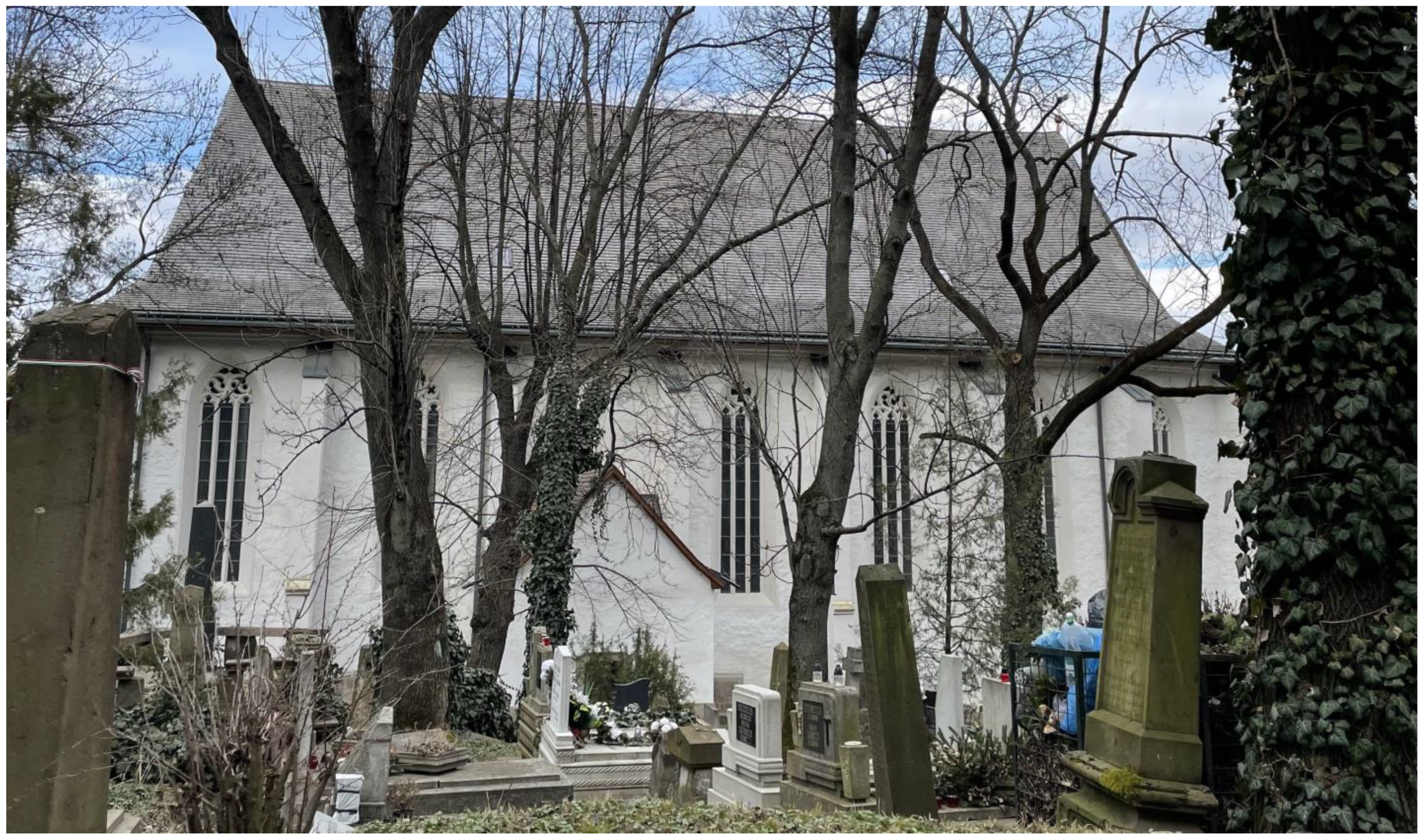
The building used for this analysis was the Avas church in Miskolc, Hungary (Figure 1). It was the most important parish church of the town in the Middle Ages, consecrated to the King Saint Stephen. By that time, Miskolc was a medium-sized market town with limited privileges. Contemporary sources testify that the predecessor building of the current church existed already in 1323. According to modern excavations, this early building was a smaller church with one single nave and a tower on its west side. The current building was built between 1453 and 1489 as a spacious hall church with a nave and two aisles. The previous church was demolished, and only its tower was kept. The foundations of the walls of the previous church served as the foundations for the internal pillars of the new church, and the lower storeys of the tower were incorporated into the volume of the new church. The designer and master builder of the building is unknown, although a source from 1489 mentions the parish priest of Miskolc in this context (Michaele de Themeswar arcium liberalium facultatis Baccalaureo, nostro scilicet plebano, qui ab … a fundamento Ecclesiam nostram Sancti Stephani Regis cum prefata Capella vna nobiscum construere et edificare inceperat) [19] (p. 59).
According to the contemporary sources, in 1663 the church was already in ruins. It is almost certain that it was demolished in 1544 when Ottoman troops attacked Miskolc and destroyed most of its buildings. By that time, Miskolc was protestant, and in the 1660s the building was renovated by the Calvinists. Since then, it has been a Calvinist church (for the history of the church, see [20,21]).
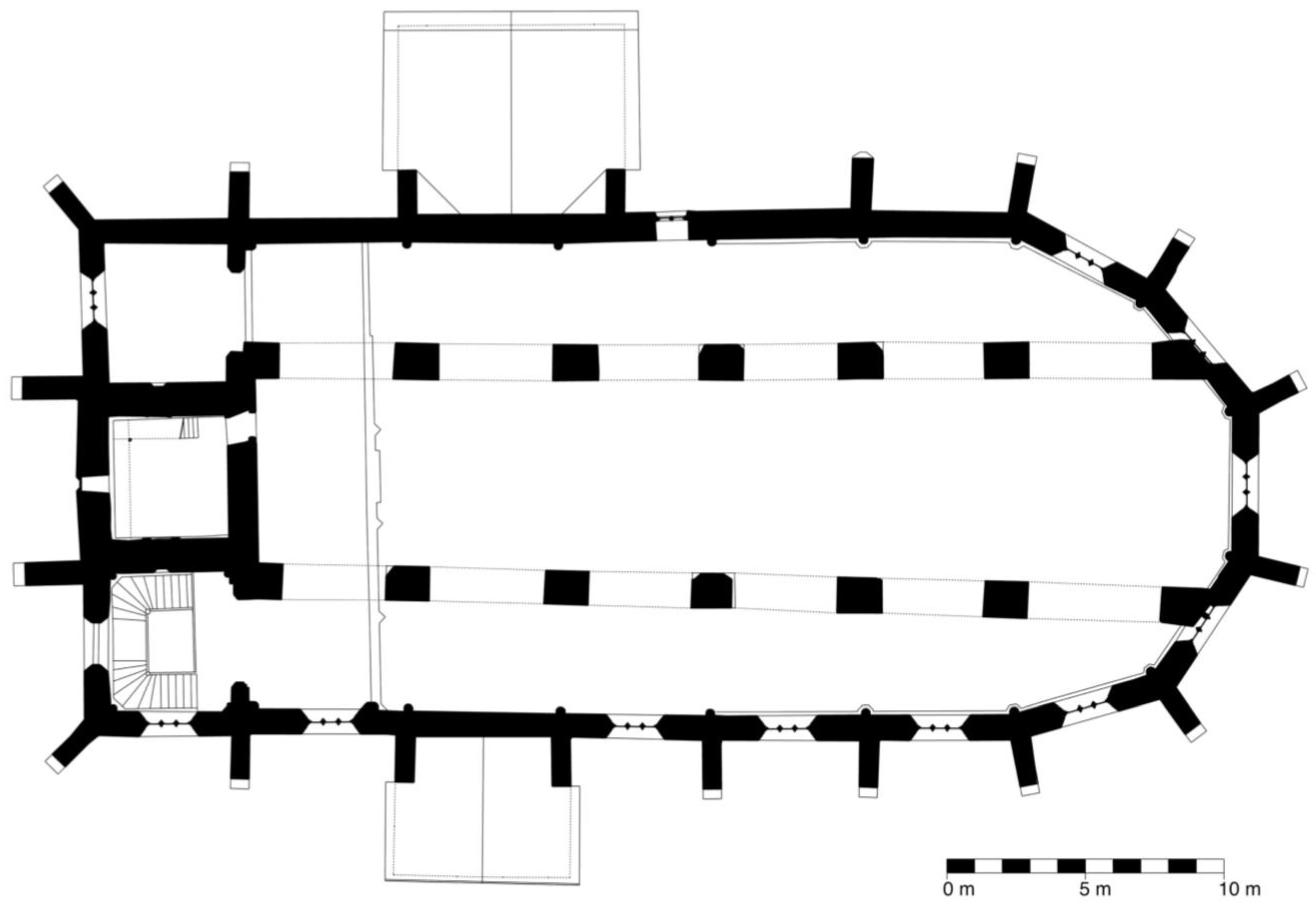
To conclude, the walls of the current building date back to the second half of the 15th century, except for the walls of the earlier tower. The internal pillars are from the 1660s, and so are the wooden ceiling and the roof structure (Figure 2).
In 1941, archaeological excavations took place in the building. These excavations brought to light the foundations of the medieval pillars in the choir. Unfortunately, the results of this excavation were published only in 1970 after the death of the head archaeologist [22]. This excavation and the renovation in the 1970s brought several stone fragments to light, which have not been surveyed and catalogued so far [23].
In 2016, an extensive laser scan survey took place, recording the current state of the building in every detail. It was followed by a photo scan survey of the stone fragments. The current study was based on these surveys.
At first, an attempt was made to reconstruct the possible design process of the medieval layout (and the layout itself). To achieve this goal, medieval design methods were tested on the laser scan survey of the church. Most importantly the rules from the so called Unterweisungen of Lorenz Lechler (1516) were tested (for the contemporary sources about medieval design methods see [3]).
Then, a theoretical reconstruction of the demolished net vault was made. According to Szekér György, the theoretical reconstruction as a method records the achievable scientific knowledge of the monument. There are multiple levels according to the level of the extractable information [24]:
- ‘in situ’ existing parts;
- anastylosis: elements which can be put back in their original position;
- reconstruction: undisputedly verifiable concepts;
- logical hypothesis: in some way assumable concepts;
- total hypothesis: unprovable ideas.
In some spaces of the church there were almost no data available about the original vault. In these places, the theoretical reconstruction was a total hypothesis. Here, generative methods were tried out. Based on the available information and on analogies, algorithms were made to generate the geometries. The existing parts (mostly the in situ vault springings and the vault fragments) served as constants, and the data for the randomised variables were obtained from contemporary analogies. The results were possibilities. It is sure that the original vault configuration was different, although similar. Unfortunately, it is now impossible to tell how it originally looked like.
Architecture is the art of space making. According to Nikolaus Pevsner, “what distinguishes architecture from painting and sculpture is its spatial quality. In this, and only in this, no other artist can emulate the architect. Thus, the history of architecture is primarily a history of man shaping space, and the historian must keep spatial problems always in the foreground.” [25] (p. 19). It is not easy to analyse and grasp spatial quality. A useful method for comparative quantitative analysis is the so-called visual graph analysis, from the set of tools of space syntax [26]. Space syntax is usually referred to as a configurational approach, where the relationship between the parts is the main subject of investigation [27] (p. 17). To examine the differences between the late Gothic (Catholic) and early modern (Calvinist) layout of the church, a visual graph analysis of the two states was made.
3. Results
3.1. Reconstruction of the Design Process
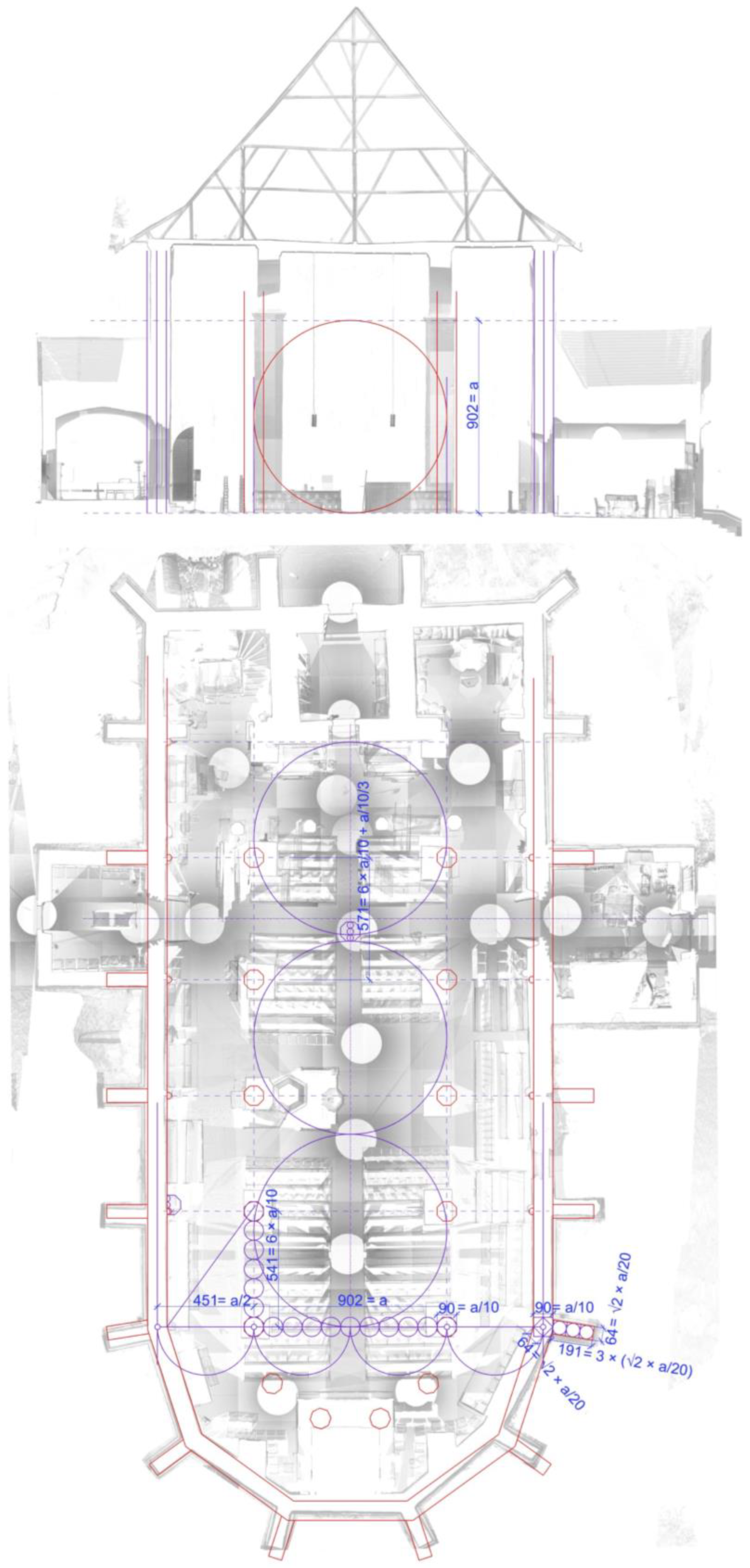
The horizontal section of the point cloud above the floor level precisely recorded the position of the walls and pillars of the church (Figure 3). It can be clearly seen that the choir polygon was very irregularly executed (more about this in Section 4).
Since the current rectangular pillars are not part of the original concept, they were ignored in the analysis. In the Unterweisungen of Lechler, the main design module is the span of the nave in the choir (a). The rules discussed in the following are published in [3] (pp. 146–151 and p. 160). Since the exact position of the original pillars is unknown, this span could not be measured, but the total span of the choir (including the two aisles) could be: it is 1803 cm, measured between the wall axes. The thickness of the walls is 89–91 cm (it varies because of the ashlar masonry and the various thicknesses of the plaster), which is 1/20 of the span (90.2 cm). According to the Unterweisungen, the wall thickness has to be 1/10 of the span of the nave (a/10), and the width of the aisles has to be the half of the nave (a/2). Thus, the entire width of the choir will be 2a. Thus, Lechler’s rules on wall thickness were valid for the Avas church (Figure 4).
Provided that Lechler’s rules apply for the relationship between the nave and the aisles, the original position of the internal pillars could be reconstructed. Based on the measured span between the wall axes (1803 cm), the width of the nave (so the a) is 1803/2 = 902.5 cm. Moreover, the width of the original pillars is known because a pillar fragment survived. The width of it is 89–90 cm. Its surface is not flat, so it could not be measured more precisely, but this size equals with acceptable tolerance the width of the walls, i.e., a/10. On the interior surface of the walls, the vault springings have survived, so, together with the data about the nave width, the original position of the pillars could be defined.
Based on the excavations in 1941, it is known that originally four pillars existed in the choir. This is an unusual layout for hall churches, because the number of the pillars in the choir is usually the half of the number of the corners of the choir wall. The choir of the Avas church has four corners (plus the two where it meets the aisle walls; it is a half decagon). The majority of similar hall churches made of stone have only two choir pillars (for example, Ingolstadt, Frauenkirche; Bautzen, Dom; St. Michael, Schwäbisch Hall). A few examples for the four-pillar layout can be found only among the northern brick churches (Stendal, Szczecin Verden). The reconstructed position of the pillars fit to the foundations revealed by the archaeologists.
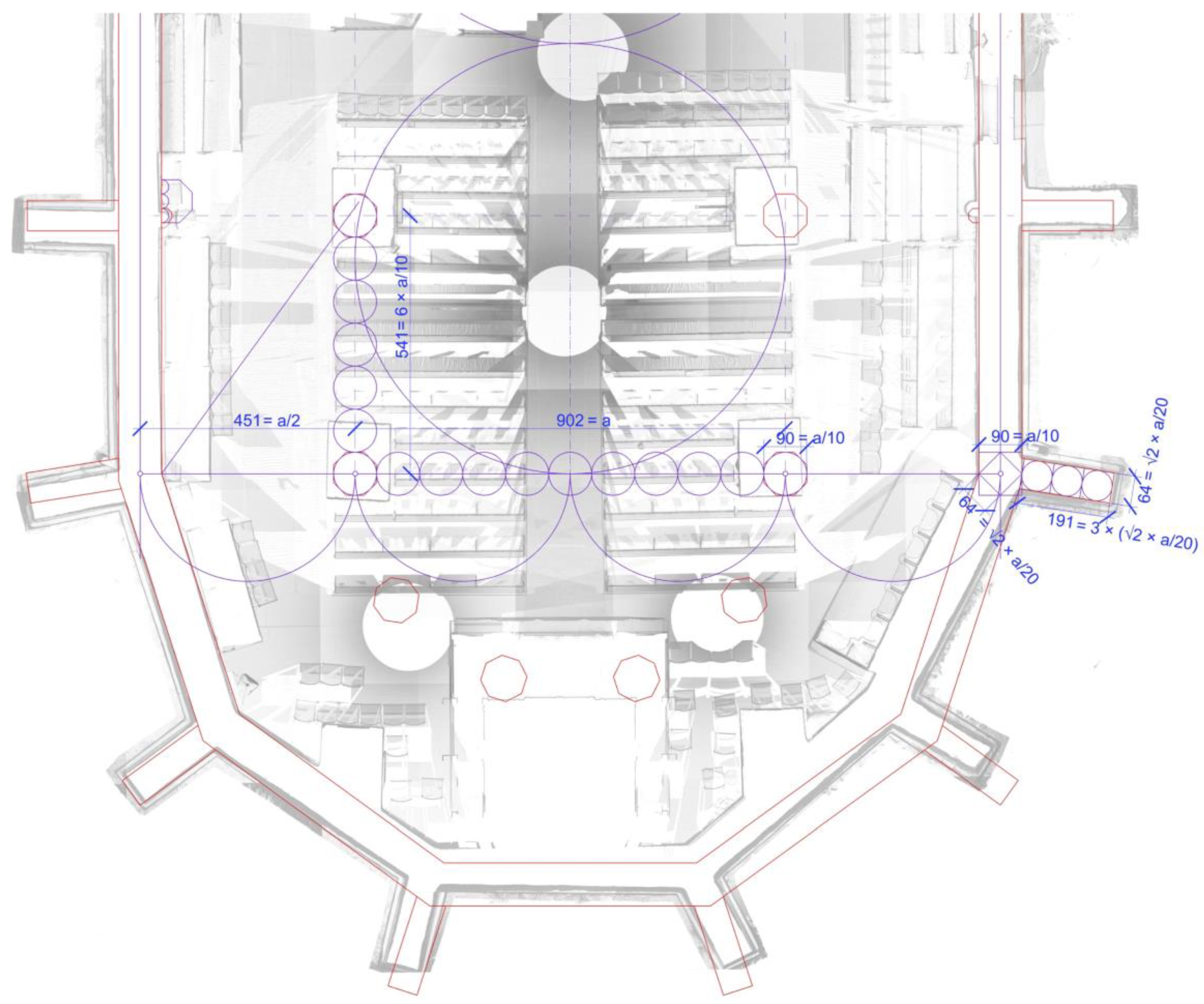
Regarding the size of the buttresses, Lechler gives two methods. In the first, the width of the buttress is the same as the wall thickness (a/10), and the length is the same as the length of the diagonal of an a/10-sided square ( × a/10). In the other version, the width is × a/10, and the length is the double of the width. Applying these rules to the dimensions of the Avas church, the size of a buttress would be either 90 cm × 127.5 cm, or 127.5 cm × 254 cm. In contrast, it is actually 64 cm × 194 cm. So, none of these rules were valid for these buttresses, but their size can be constructed on a similar way: the width of the buttress (64 cm) is × a/20, and the length can be considered as triple the width (194 cm), with the usual few centimetre tolerance due to the inaccuracy of the ashlar and plaster. Although the proportions are not the same as in the Unterweisungen, the method is very similar, involving square root and multiplication. The × a/20 involves the so called quadratur. If a square is drawn with the side length of the wall thickness (a/10), then the middle points of its sides are connected, and the side length of the resulting square is the thickness of the buttress (Figure 4).
Regarding the length of a bay (the distance between the axes of the pillars measured parallel to the longitudinal axis of the church), Lechler provides several rules. In the first one, the length of the bay is 4 × a/10, so four times the thickness of the wall. In the second one it is 4 × × a/10, so it is slightly larger. In the case of the Avas church, the first value would be 360.6 cm, and the second 509.97 cm. It was difficult to measure the exact length of the bay due to the irregular construction (the side walls of the church are not parallel, and the positions of the buttresses outside and the springings inside do not match), but it could be averaged as 541.1 cm. One bay out of the four is slightly larger, and this will be discussed later. The length of 541.1 cm can be calculated as 6 × a/10. So, again, the size is different, but the method of calculation (multiplication of the wall thickness) is the same.
The Avas church has two portals on its side opposite to each other: one on the north and one on the south side. The bay of the portals is larger than the others. This seemed conceptional, because the size of this bay is 571.2 cm, so the difference is one third of the wall thickness (30 cm). The width of the polygonal pilasters under the springings in the nave has the same value. This dimension seemed to be the length of the foot used for the construction, so the width of the pillars and the thickness of the walls is 3 feet.
It was not possible to analyse the cross section of the church, even as detailed as it was made on the floor plan, because of the demolition of the vaults. It is likely that not even the cornice is at its original height. However, the position of the vault springings has been preserved. They are at a height of 900–903 cm, which can be considered to be the same as the module (the width of the nave, a). This matches the rule of Lecher for the height of the springings in the nave and aisles.
3.2. Theoretical Reconstruction of the Vault
The in situ elements serve as the most important data for any theoretical reconstruction. In the case of the Avas church, the vault springings and the walls containing them were these parts. An obvious problem was the irregularity of the construction. Compared the actual polygon of the choir to the regular decagon, it could be seen that the former is distorted, mostly on its north-east corner. The question arises as to what the actual object of the reconstruction should be: the actual vault built with several distortions, as evidenced by the inaccuracies in the floor plan, or the plan on which it was built? As the construction rules of the plan were reconstructed above, and as the exact location of the original pillars is not known, the decision was made on the latter. Exceptions to this were the small spaces next to the former tower, which could not be included in the construction geometry of the floor plan and are separate from the vaulting system of the nave and aisles.
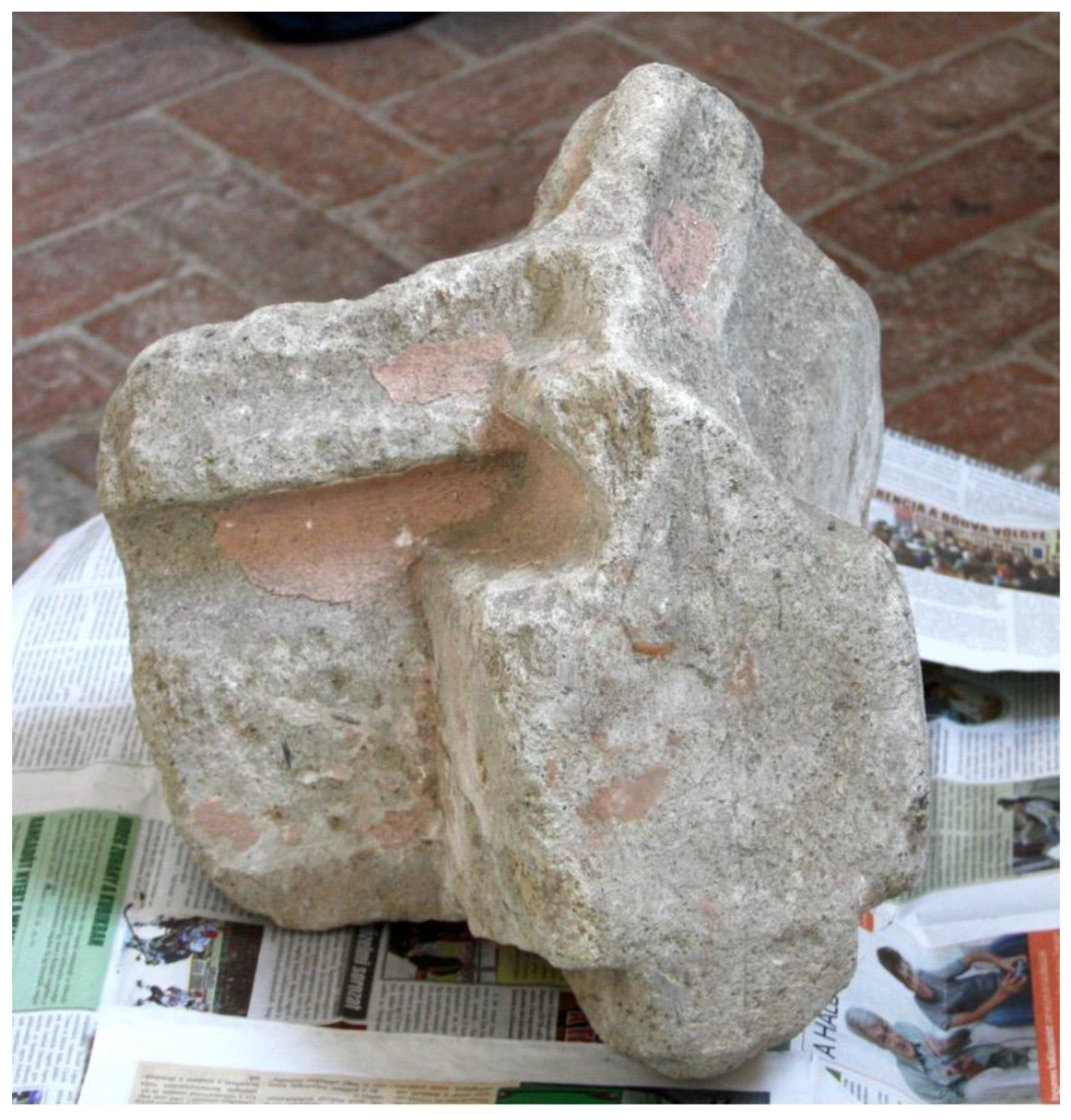
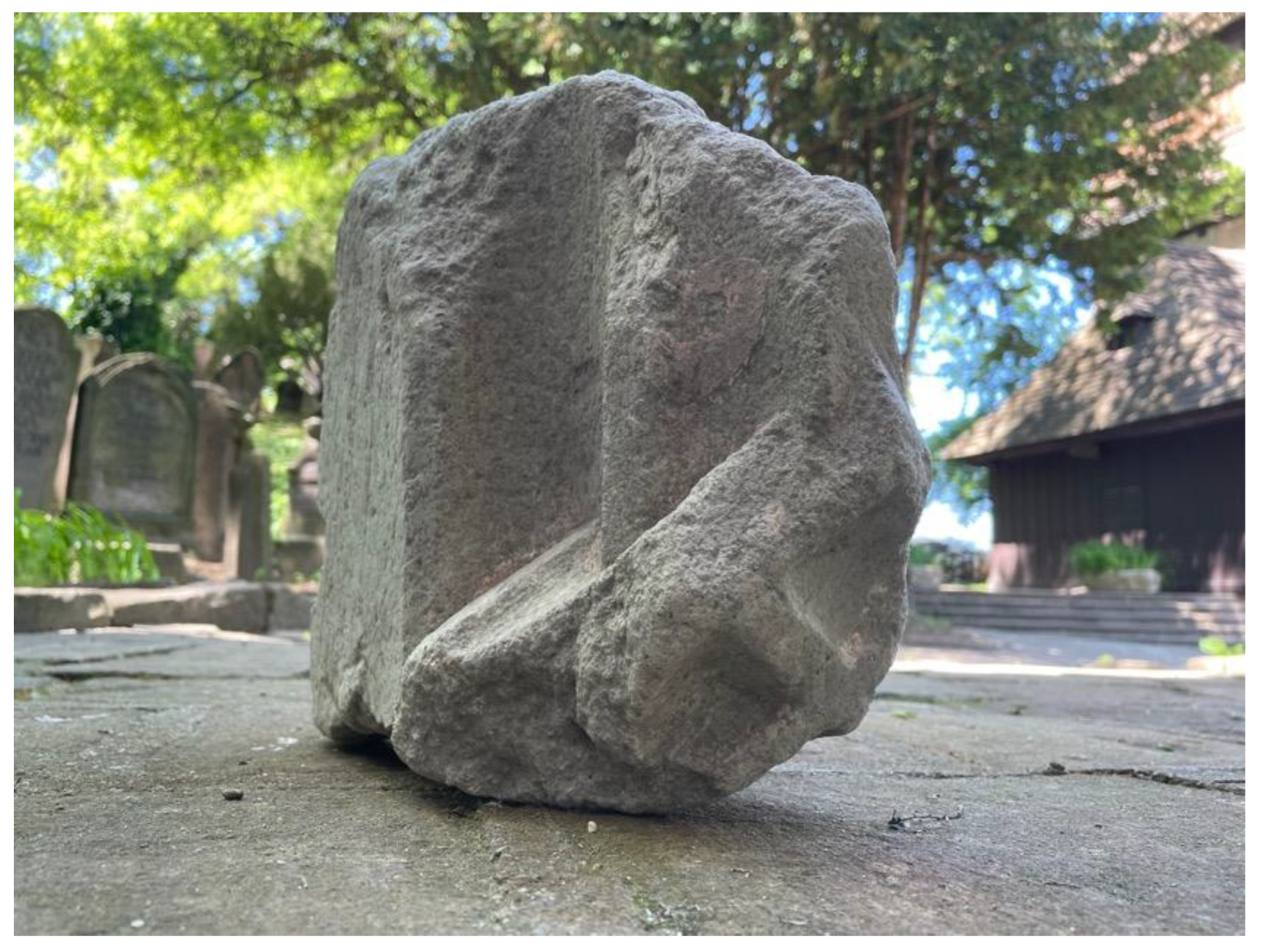
Only one rib junction has survived more or less intact. This is Y-shaped, with two branches coming from below, the third going upwards. Its original location is unknown, and its branches enclose the following angles: 146, 110, and 104 (in degrees). Let us refer to it as Fragment A (Figure 5). Beside this, there are two other rib junctions, but almost half of both have been brutally destroyed. Let us refer to them as Fragment B and C (Figure 6). The two junctions seemed identical. They are symmetrical. The rib in the symmetry axis arrives from below, and the two others go upwards. The angle between the rib in the axis and one going upwards was measurable; it is 109. Since the fragments are symmetrical, that means that the other angle in the same position is the same, so the angle between the upwards-going ribs is 142. These values are roughly the same as on the almost intact junction.
One more rib fragment has survived that can be connected to the late Gothic vault. It is an unusual springing, with only one rib (Fragment D). Since the walls of the church are standing, it is likely that it was walled up into one of the destroyed nave piers.
The in situ springings in the wall of the aisles and the choir are three-branched. The middle branch is in the bisector, and the two outer ones close to the wall are at 36 degrees, both in the choir and in the aisles. This 36-degree angle is a quarter of the interior angles of the choir polygon constructed into a regular decagon.
The 36-degree angle assumes a simple cross-vault in the aisles. However, the diagonal arches do not arrive exactly at the reconstructed centre of the pillars (the difference is only 12.5 cm). This may be intentional (leaving room for a thicker arcade arch), but it is also possible that there is a conflict between the geometrical order of the floor plan and the order in which the vault was constructed.
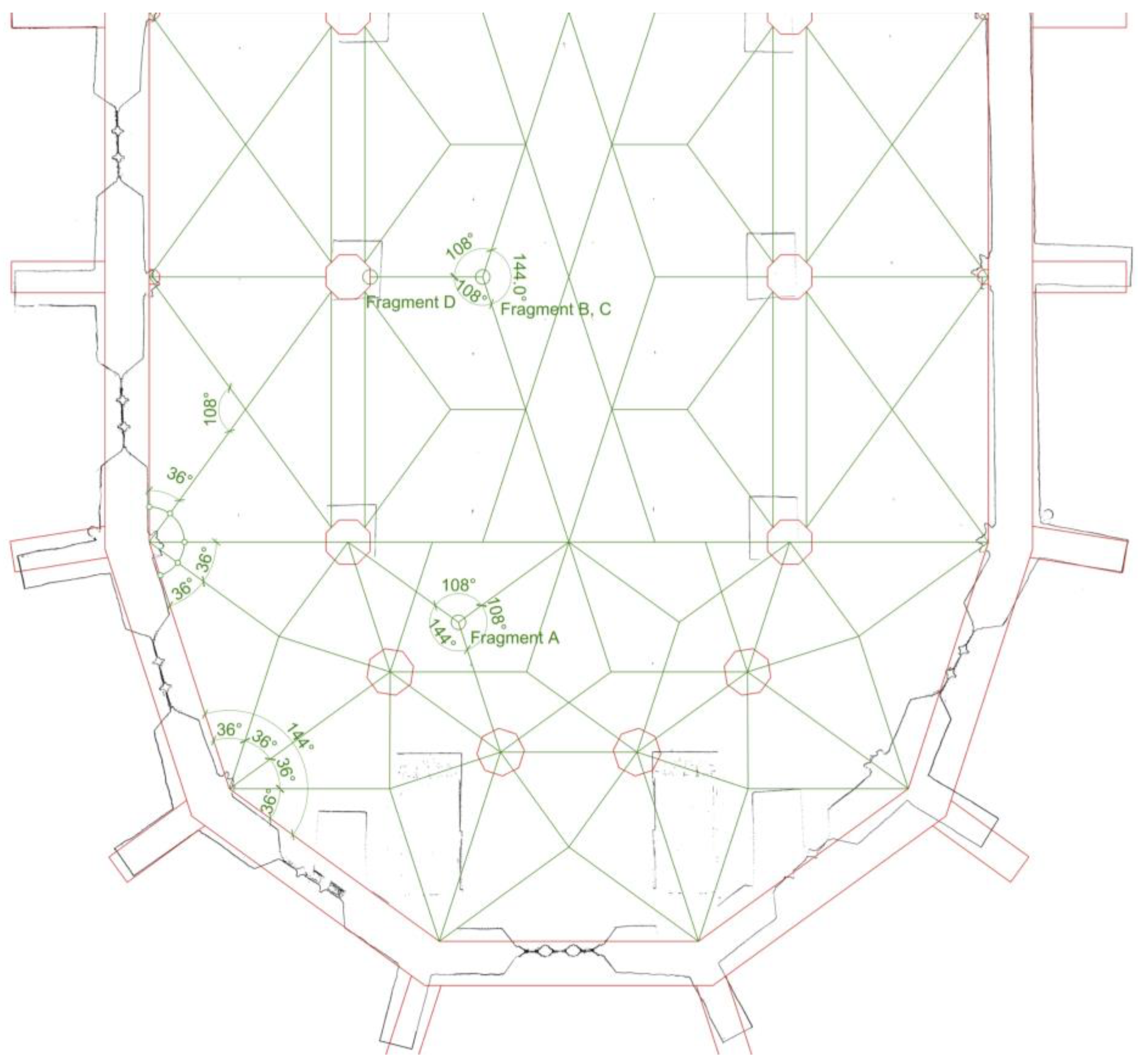
In the aisle of the choir, an irregular cross vault could be assumed based on the springings, where the ribs break at the crown. Several analogies are known from a similar system in a similar situation. Fragment A provides information for the reconstruction of the vault of the choir. This fragment fits into a system with a difference of a few degrees, where the two ribs coming from below run parallel to the corresponding sides of the choir polygon (and thus the corresponding springings in the wall), and the upward-running rib runs into the centre of the polygon. The vertical angle of the branches of the fragment also supports this position (Figure 7 and Figure 8).
The reconstruction of the vault in the nave is more problematic since there are not in situ springings available. On an exclusion basis, it could be assumed that the fragments B, C, and D were from the nave. The simplest net vault configuration using these data can be seen in Figure 7. This pattern is identical with the pattern of the choir vault of the Martinskirche in Landshut, Germany. According to the literature, the roots of the architectural style of the Avas church can be traced back to the area of Landshut [28,29] (p. 683).
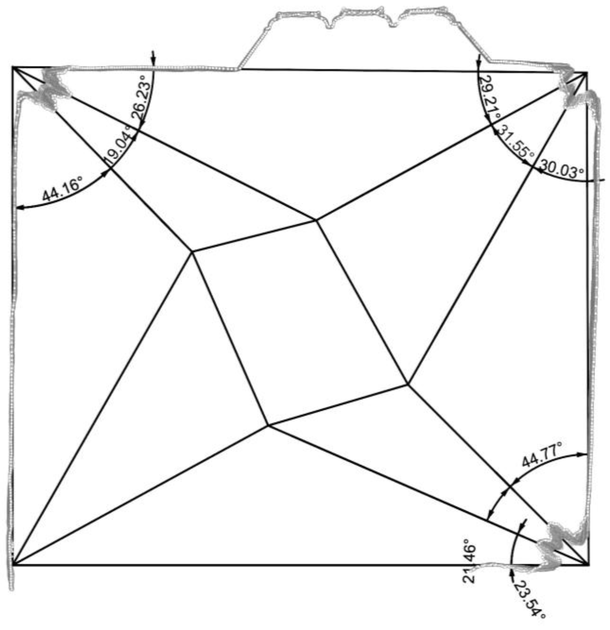
In the rectangular space on the northern side of the former tower, three springings out of the four have survived. The two opposite ones have the same angles in the same direction (with some tolerance). Based on this, central symmetry could be assumed, so the missing fourth springing could be drawn based on the opposite one. By simply connecting the directions, the easiest solution is a twisted star, which is very irregular, but so are the surrounding walls (Figure 9).
In the space in the southern side of the former tower only one springing has survived. This serves inadequate information for a reconstruction.
3.3. Generative Experiments
3.3.1. Side Aisles
The 3D model for the ribs of the side aisles could be relatively straightforwardly generated by algorithm. If the diagonal arch is a half-circle (which is the usual method), then the radius of each rib is equal to the half of the diagonal of the rectangular bay. Thus, only three input parameters are needed:
- The width of the bay;
- The length of the bay;
- The profile of the ribs.
In the side aisles of the Avas church, all of the above three are known. The length of the bay could be measured on the in situ pilasters, the profile of the ribs could be obtained from the in situ vault springings (and from the rib fragments with the same profile), and the width of the bay was the result of the geometric construction above.
The algorithmic steps are as follows:
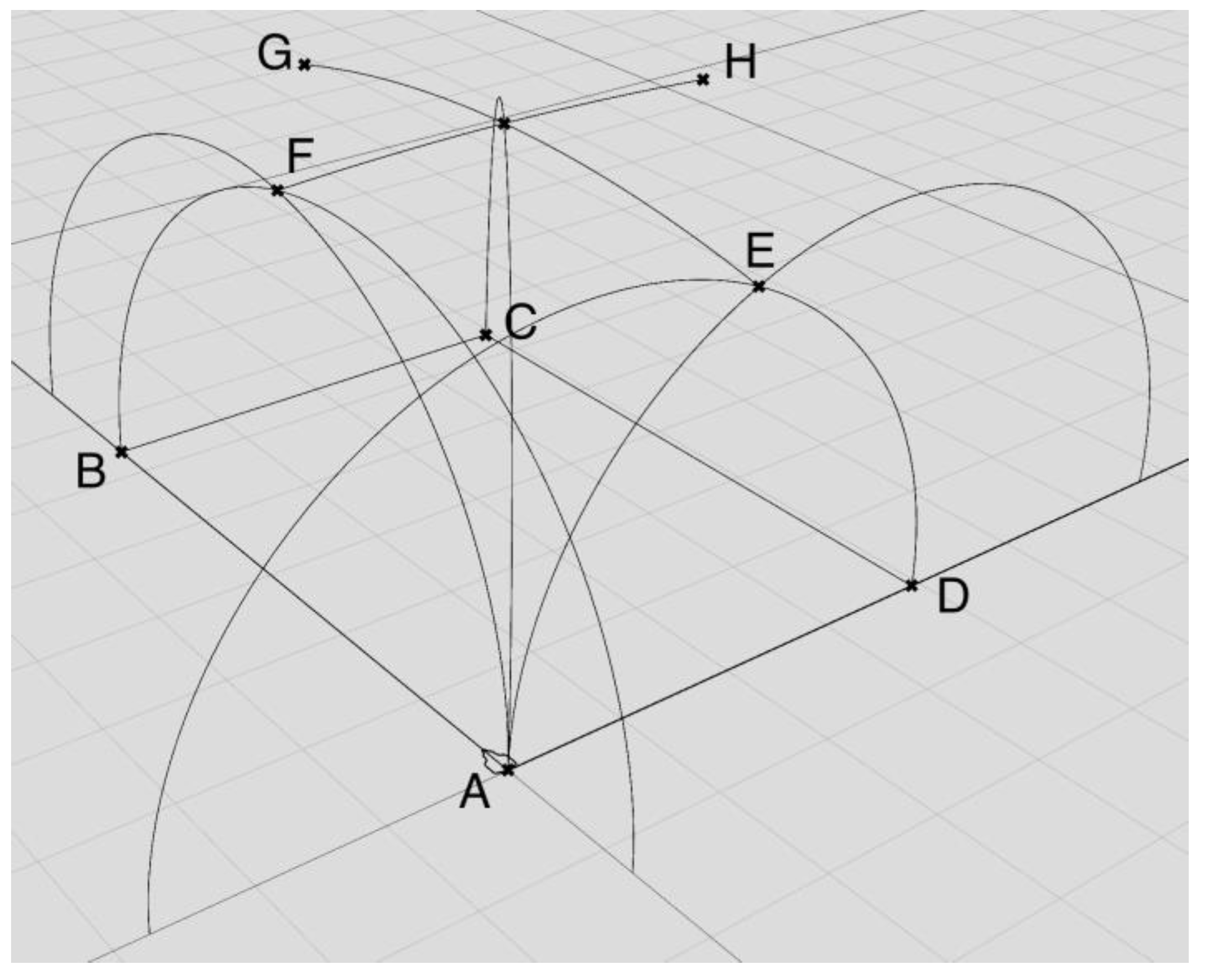
- Create a rectangle using the width and the length of the bay. Let us refer to the corners of the rectangle as A, B, C, and D, clockwise;
- Draw the diagonal arches as half circles using the end points of the diagonals (A and C, B and D) as end points and a vertical vector at an end point as a tangent;
- Rotate and copy the AC diagonal arch around the vertical axis through point A to the vertical planes defined by the AB and AD segments; then, the same around the vertical axis through point C to the vertical planes defined by the BC and CD segments;
- Carry out the same with the BD diagonal;
- Find the intersection points of the resulting arches. There will be four points for the eight arches; refer to them as points E, F, G, and H;
- Draw the transversal arches and the arcade/wall arches between the points AE, AF, BF, BG, CG, CH, DH, and DE, using vertical tangents at the start;
- Join the relevant arches;
- Refer the profile curve from Rhino and extrude it along the four arches produced in Step 6.
Since the width and the length of the bay are the input parameters, this algorithm can be used to generate a Gothic cross-vault for bays with different sizes as well.
3.3.2. Southern Stellar Vault
In the case of the southern stellar vault, there was not enough data to create a theoretical reconstruction. Only one springing has survived in situ in good condition, and no stone fragments could be identified as a junction of that vault. So, the pattern of the vault could be the subject of a generative experiment where the known parameters are fixed and everything else is randomised based on the usual stellar patterns of the era. In this algorithm, the input parameters are the following:
- The width and the length of the room;
- The number of ribs starting from the corners;
- The angle of the ribs at the corners.
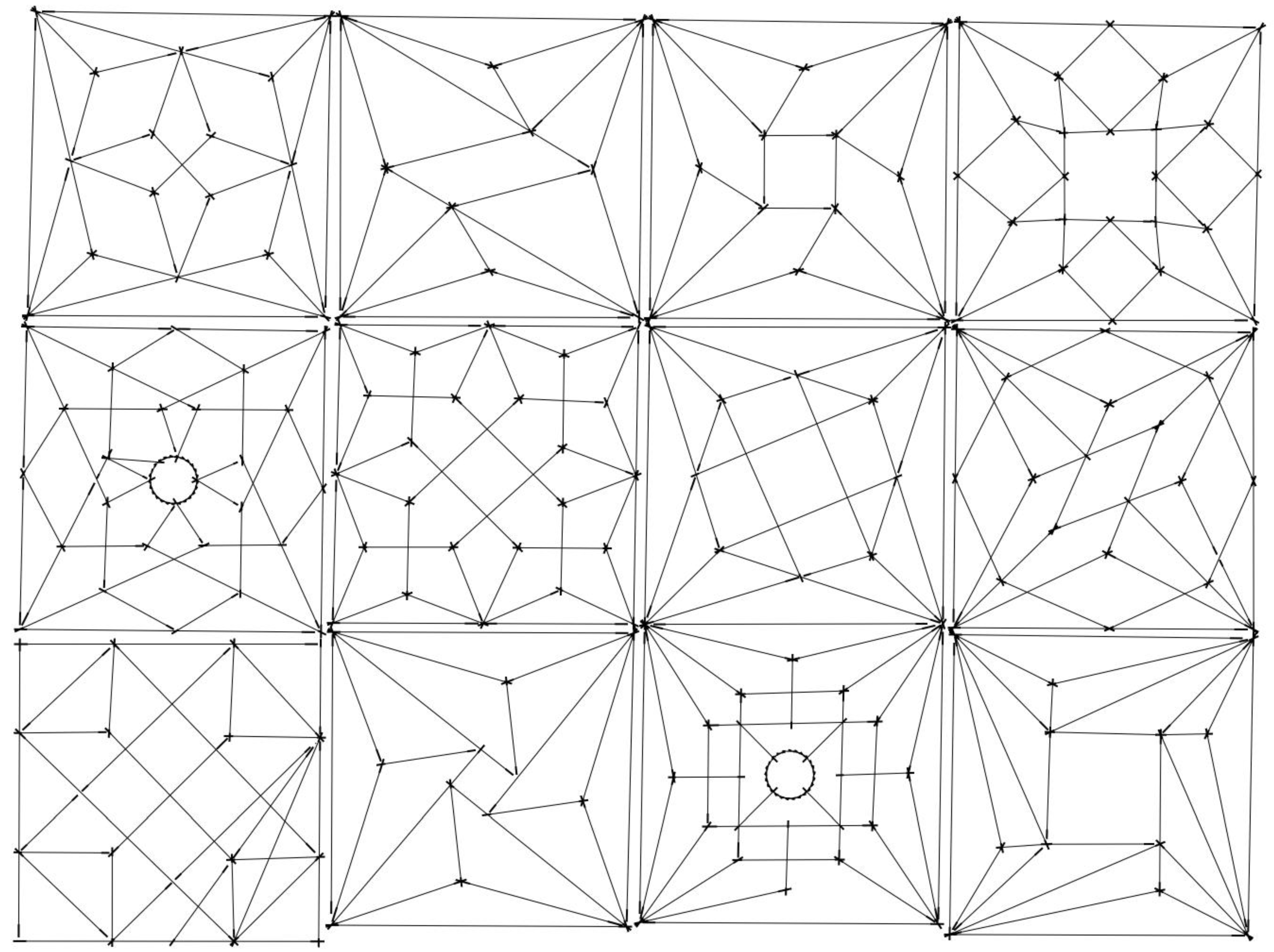
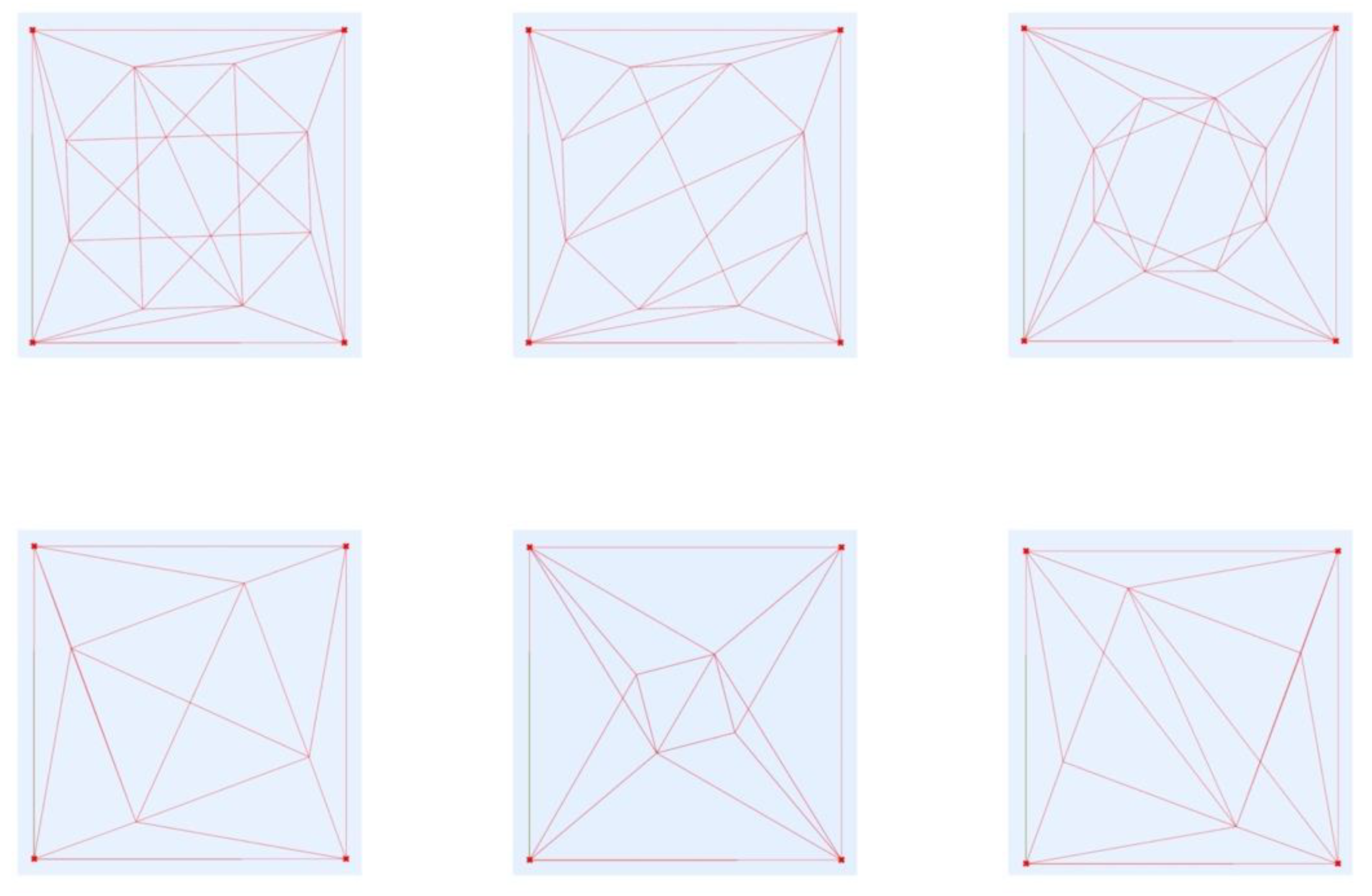
Before discussing the special case of the Avas church, let us begin with a general, square-shaped form with two or three ribs in the corners. Many variations for this theme can be seen in contemporary manuscripts, for example on page 23 of the portfolio of Hans Hammer (Figure 12). In the algorithm, central symmetry is used, which means that the angles of the ribs will be the same in the opposite corners. Then, the angles between the wall and the adjacent ribs are randomised using 10-degree steps (smaller angles are very uncommon). The resulting lines are connected. Due to the central symmetry, their intersections will form a square. A great variety results by randomly connecting these points to the corner points. Another method is to construct an octagon from the four intersection points, rotating them 45 degrees around the centre of the square to obtain the other four points (this can be set with a switch in the algorithm). Then, a secondary pattern can be generated, connecting the points of the octagon in random order and/or in reverse order. Some examples for both the internal square and octagonal variation can be seen in Figure 13. On some patterns, a few superfluous lines could be observed due to the hands-off nature of the algorithmic form generation. These were intentionally not erased by hand, because similar superfluous lines can be observed on contemporary vault sketches too, for example on the bottom-left pattern of Figure 12.
In the case of the Avas church, the following parameters were given (so were fixed as constants):
- The width and the length of the room, values in cm: 495 and 410;
- The number and the angles of the ribs in the north-west corner (where the springing has survived in situ): 3 (integer), 21.8, 24.0, 16.7, and 27.6 (angles in degrees between the ribs and between the walls and ribs, clockwise);
- The number of the ribs in the south-west corner: 2 (integer). The angles could not be measured.
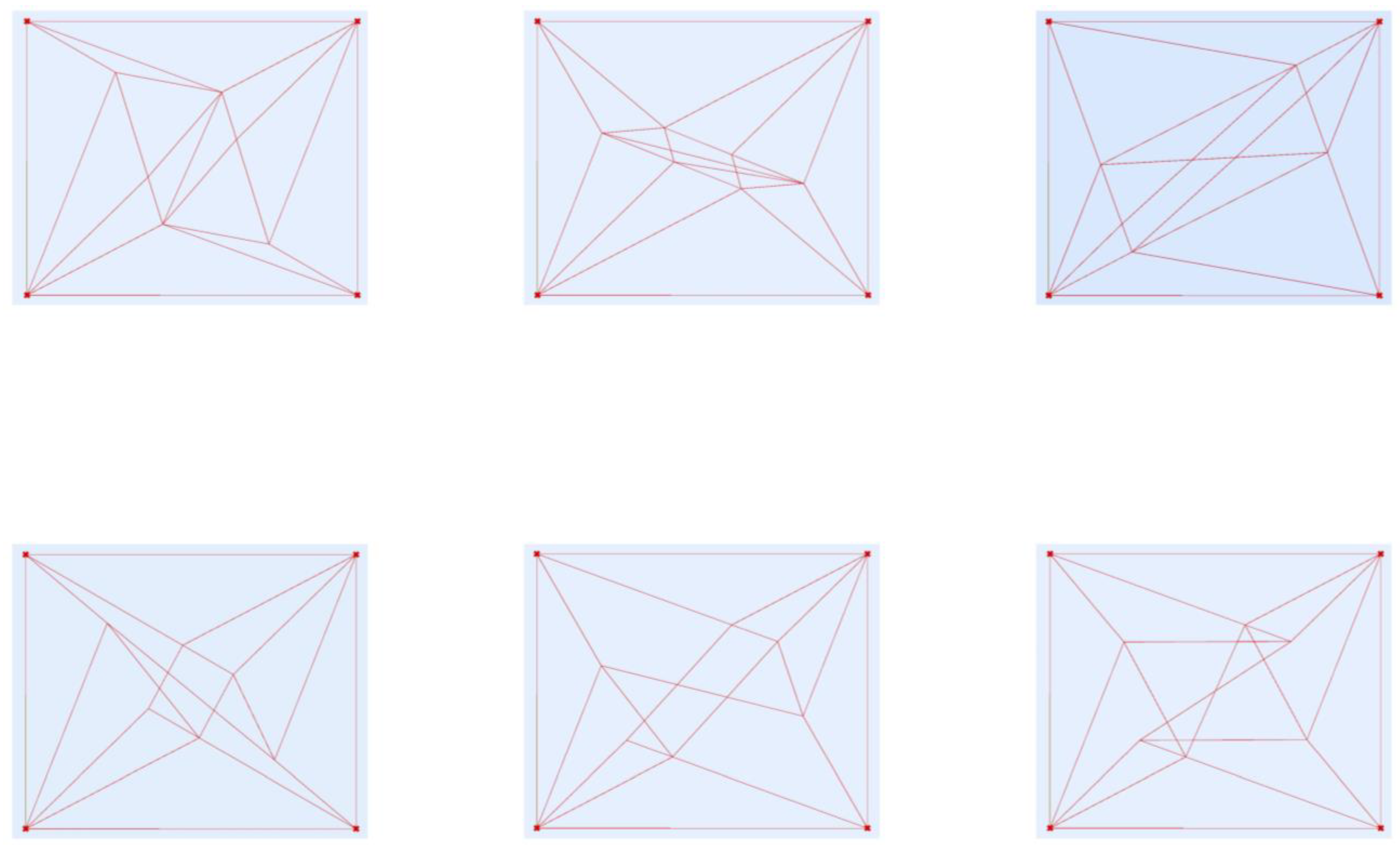
Since the number of the ribs in the corners are different, central symmetry could be assumed. So, the angles in the NW and SE corners are given, and in the remaining two corners they were randomised. The ribs adjacent to the walls intersect each other, as in the example discussed above. In the case of the middle ribs in the NW and SE corner, two methods were used. In the first one, the middle ribs were intersected with the polyline defined by the intersection points of the ribs adjacent to the walls. Then, the intersections were connected randomly to form a secondary network. In the second method, the middle ribs intersected with the rib next to them clockwise. Then, the intersections were again randomly connected. Some variations can be seen in Figure 14.
3.4. Configurational Analysis
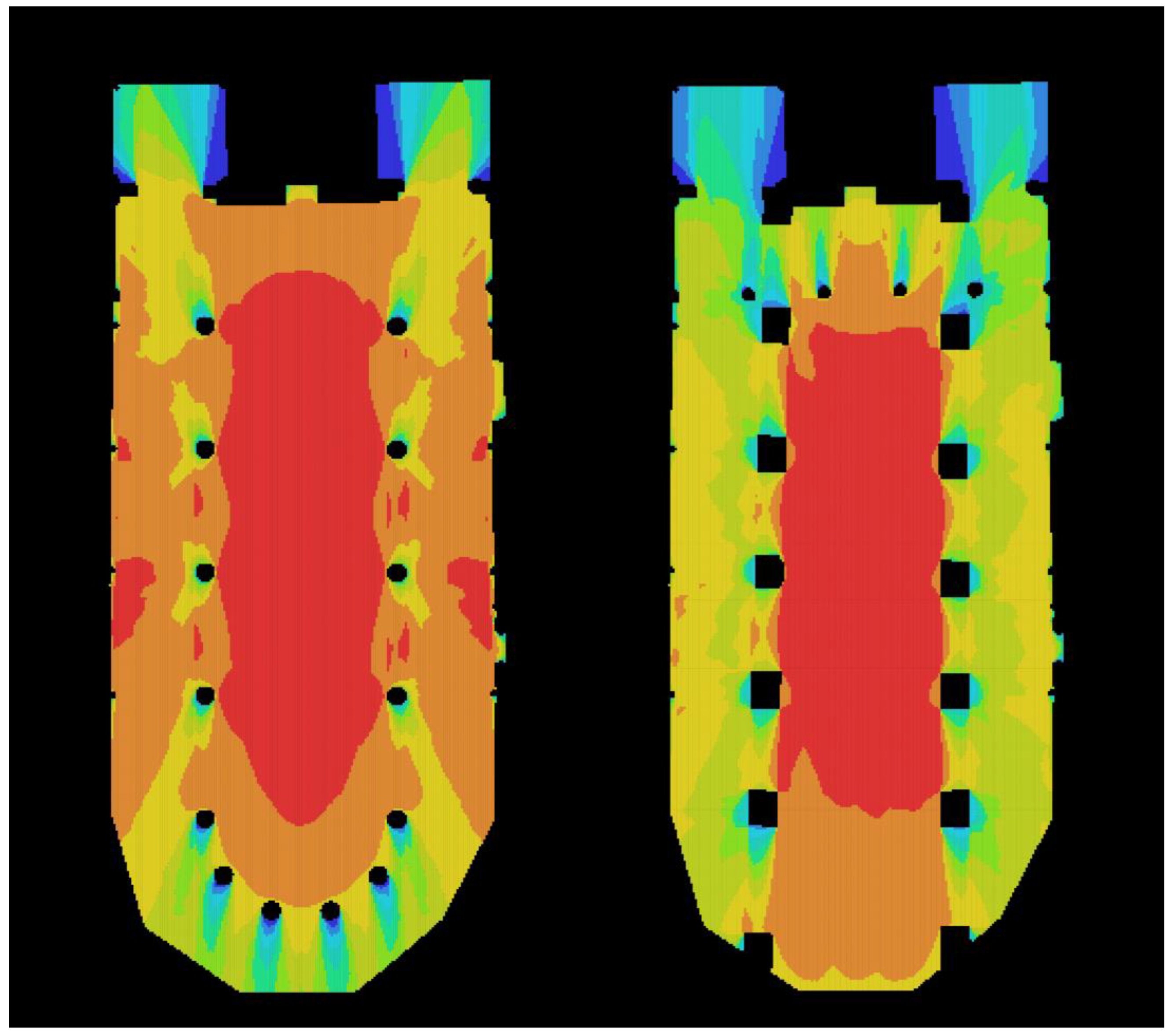
At first sight, the late Gothic layout of the church was similar to the current one: one nave with two aisles, and five pairs of free-standing pillars in the nave. There were originally four more pillars in the choir, but the current wall piers on the western and eastern side did not exist. An important difference is the shape and the thickness of the pillars. The medieval ones were octagonal and slenderer than their early modern rectangular counterparts. It is commonplace in the literature that the thick early modern pillars affected the spatial quality of the church in the wrong direction. See, for example [30] (p. 18). The sense of the space is a phenomenon which is not easy to describe. The visibility graph analysis from the tools of space syntax seemed suitable for this purpose. A visibility graph shows how visible a given point in space is from other parts of the space. Values grow with the number of spots from where the point is visible and are displayed on a heat map (red: higher values, blue: lower values). The visibility graph displays the relationship of each point of the space to the whole. The properties of the visibility graph are related to spatial perception [26].
In Figure 15, the visibility graph of the medieval state (left) can be seen compared to the current state (right). The difference is striking. The medieval space was transparent, with almost every point having relatively high values. Blue colour appeared only in the small spaces north and south of the tower and behind the pillars of the choir to a smaller extent. The aisle of the choir and the eastern corners of the aisles were yellow, the aisles were orange, and almost the entire nave was red.
In contrast, the current layout was visually (and so spatially) more segregated. Most of the nave was red. Its eastern side was orange. Everything else was green and blue, with some yellow. Even the side spaces next to the tower had worse visibility values than in the case of the medieval layout. The whole layout had a strong axiality, and the different spaces had a subordinate relationship.
The question emerges whether the spatial properties discussed above were the result of conscious planning or not. It seemed that the transparent effect of the medieval layout was conscious, while the axial, spatially segregated effect of the early modern layout was not. As Erwin Panofsky discusses in his seminal work, the spatial unity, the “boundless interior” was an important endeavour of late Gothic architecture [16] (p. 43). This endeavour can be clearly read from the visibility graph.
In contrast, the strict axial layout and spatial fragmentation contradicts the liturgical use of a Calvinist church. There is no high altar, and there are not any altarpieces in Calvinist liturgy. The pulpit and the Communion table are located in the centre of churches, and so is the case in the Avas church, which has been Calvinist since its reconstruction in the 1560s.
4. Discussion
Although the geometrical methods used in Gothic design seem rigid, the case study showed that they were flexibly adaptable and gave space for variations and improvisations. The methods recorded in Lechler’s Unterweisungen echo the executed layout of the Avas church. In fact, the most important proportions were so strictly followed that it can be assumed that they were generally used in the late Gothic architecture in Central Europe (i.e., the ratio of the width of the nave to the aisles, the ratio of the wall thickness to the nave, the ratio of the columns to the walls, and the ratio of the height of the springings to the nave). It can be stated that even a relatively simple rural church was the subject of conscious architectural design, and the layout was executed using a plan and not by ad-hoc decisions on site.
The deviations from Lechler’s rules were more likely variations than the sign of a different approach. For example, the length of the bay was calculated by the same method (the multiplication of the column thickness), and only the number differed (six instead of four). The same was true for the size of the buttresses; the procedure was similar, but the variables were different.
There were major irregularities in the execution of the church. It seemed that the task of setting out was too difficult to conduct precisely. The largest deviation could be observed in the north-east side of the church: here, the deviation of the actual corner of the choir from the plan was 75 cm. It is likely that the irregular setting out was caused by the terrain: the church is sitting on a slope, and its steepest part is here.
In the case of the late Gothic vault, there was more space to play then in the case of the floor plan layout. The rules were not so strict here, and the number of possible variations was really infinite. The algorithms created involved only a few steps and rules, but even these algorithms generated a large variability with the changing of only a few parameters. This fact, together with the irregularities of the construction, meant that it was impossible to reconstruct the vault from the springings and the few fragments. Possible variations could be created, but it could not be decided which configuration was the actual one.
5. Conclusions
The most important results of this case study are summarised above. The method applied here can be used in the future on other similar buildings. The Kingdom of Hungary was an important centre of Gothic art in central Europe, but its buildings are underrepresented in the international literature. One reason for this is that the majority of the Gothic monuments in Hungary were damaged or even destroyed under the Ottoman occupation. Reconstructing the architecture of the medieval Kingdom of Hungary is a kind of detective work, so the stone fragments and the methods of Bauforschung had a distinguished role here.
In an international context, revealing the procedural logic behind the design can serve as new information about any standing building. Research on Gothic design methods has always been an important discipline, but only a very small number of the existing buildings have surviving original plans. So, the buildings themselves (using laser scanning) can tell the story of their design if we are able to reconstruct the procedural steps behind it.
Funding
This research received no external funding.
Data Availability Statement
Not applicable.
Conflicts of Interest
The author declares no conflict of interest.
References
- Velte, M. Die Anwendung der Quadratur und Triangulatur bei der Grund-und Aufrißgestaltung der Gotischen Kirchen; Birkhäuser: Basel, Switzerland, 1951. [Google Scholar]
- Roriczer, M.; Shelby, L.R.; Schmuttermayer, H. Gothic Design Techniques. The Fifteenth Century Design Booklets of Mathes Roriczer and Hanns Schmuttermayer; Southern Illinois University Press: Carbondale, IL, USA, 1977. [Google Scholar]
- Coenen, U. Die Spätgotischen Werkmeisterbücher in Deutschland als Beitrag zur Mittelalterlichen Architekturtheorie. Untersuchung und Edition der Lehrschriften für Entwurf und Ausführung von Sakralbauten. Ph.D. Thesis, RWTH Aachen University, Aachen, Germany, 1989. [Google Scholar]
- Bork, R. The Geometry of Creation: Architectural Drawing and the Dynamics of Gothic Design; Ashgate: Farnham, UK, 2011. [Google Scholar]
- Heyman, J. The Stone Skeleton. Structural Engineering of Masonry Architecture; Cambridge University Press: Cambridge, UK, 1997. [Google Scholar]
- Bereczki, Z. The Structural Analysis of the (Demolished) Medieval System of St. Elisabeth’s Church in Kassa. Pollack Period. 2014, 9, 127–138. [Google Scholar] [CrossRef]
- Frankl, P. The Gothic. Literary Sources and Interpretations throught Eight Centuries; Princeton University Press: Princeton, NJ, USA, 1960. [Google Scholar]
- Hoffstadt, F. Gothisches ABC Buch: Das ist: Grundregeln des gothischen Styls für Künstler und Werkleute; Mit zwei und vierzig Vorlegeblättern u.e. Abhandlung über Geschichte und Restauration der Deutschen Baukunst, Nebst Einem Wortverzeichnisse Über Deren Kunst-und Handwerks-Ausdrücke; Schmerber: Frankfurt am Main, Germany, 1880. [Google Scholar]
- von Heideloff, C.A. Der Kleine Altdeutsche (Gothe) oder Grundzüge des Altdeutschen Baustyles; Riegel und Wießner: Nürnberg, Bayern, 1851. [Google Scholar]
- Schuller, M. Building Archaeology; Lipp: München, Germany, 2002. [Google Scholar]
- Jobbik, E.; Krähling, J. Remodelling a Medieval Net Vault Construction. Case Study: The Apse Vault in the Catholic Church of Andocs. Építés Építészettudomány 2022, 50, 317–349. [Google Scholar] [CrossRef]
- Bork, R. Dynamic Unfolding and the Conventions of Procedure: Geometric Proportioning Strategies in Gothic Architectural Design. Archit. Hist. 2014, 1, 1–20. [Google Scholar] [CrossRef] [Green Version]
- Bereczki, Z. Generative Interpretations of Late Gothic Architectural Forms. Symmetry Cult. Sci. 2020, 31, 279–295. [Google Scholar]
- Bork, R. Late Gothic Architecture. Its Evolution, Extinction, and Reception; Brepols: Turnhout, Belgium, 2018. [Google Scholar]
- Bereczki, Z. Aratás és szüret: A későgótikus építészetről. Miskolci Keresztény Szle 2018, 14, 81–88. [Google Scholar]
- Panofsky, E. Gothic Architecture and Scholasticism; New American Library: New York, NY, USA, 1951. [Google Scholar]
- Kavaler, E.M. Renaissance Gothic. Architecture and the Arts in Northern Europe 1470–1540; Yale University Press: New Haven, CT, USA, 2012. [Google Scholar]
- Hillier, B.; Julienne, H. The Social Logic of Space; Cambridge University Press: Cambridge, UK, 1984. [Google Scholar]
- László, K.K. Adatok a miskolci Avasi templom történetéhez. A Herman Ottó Múzeum Évkönyve 1972, 11, 55–70. [Google Scholar]
- Gyulai, É. Miskolc Középkori Topográfiája. In Miskolc Története I. A Kezdetektől 1526-ig; Kubiny, A., Ed.; Borsod-Abaúj-Zemplén Megyei Levéltár, Herman Ottó Múzeum: Miskolc, Hungary, 1996; pp. 175–253. [Google Scholar]
- Gyulai, É. Az Avasi Templom és Temető Nyolc Évszázada. In Református Templom és Temető a Miskolci Avason; Dobrossy, I., Ed.; Borsod-Abaúj-Zemplén Megyei Levéltár, Herman Ottó Múzeum: Miskolc, Hungary, 2003; pp. 9–24. [Google Scholar]
- Megay, G. A miskolci Avasi templom 1941. évi ásatásának eredményei. A Herman Ottó Múzeum Évkönyve 1970, 9, 129–170. [Google Scholar]
- Feld, I. Régészeti Adatok a Miskolc-Avasi Templom és Egykori Kápolnái Történetéhez. In Vándorutak—Múzeumi Örökség. Tanulmányok Bodó Sándor Tiszteletére, 60. Születésnapja Alkalmából; Viga, G., Andrea, H.S., Schwalm, C., Eds.; Archeolingua Alapítvány: Budapest, Hungary, 2003; pp. 385–399. [Google Scholar]
- György, S. Az Elméleti Rekonstrukció, Mint Tudományos Módszer—A DIÓSGYŐRI vár Déli Fala Fülkeboltozatának Kutatása. In Régészeti Kalandozások. A Régészet Legújabb Hazai Eredményei. Új Technológiák a Kutatásban és a Prezentációban; Gábor, M.N., Ed.; Forster Gyula Nemzeti Örökséggazdálkodási és Szolgáltatási Központ: Budapest, Hungary, 2003; pp. 27–32. [Google Scholar]
- Pevsner, N. An Outline of European Architecture; John Murray: London, UK, 1948. [Google Scholar]
- Turner, A.; Doxa, M.; O’sullivan, D.; Penn, A. From isovists to visibility graphs: A methodology for the analysis of architectural space. Environ. Plan. B Plan. Des. 2001, 28, 103–121. [Google Scholar] [CrossRef]
- Kropf, K. The Handbook of Urban Morphology; Wiley: Chichester, UK, 2017. [Google Scholar]
- Csemegi, J. Az avasi templom középkori építéstörténete. Magy. Művészet 1938, 13, 255–259. [Google Scholar]
- Marosi, E. (Ed.) Magyarországi Művészet 1300–1470 Körül; Akadémiai Kiadó: Budapest, Hungary, 1987. [Google Scholar]
- Béla, I.H. A Miskolci Avas Műemlékei; Képzőművészeti Alap Kiadóvállalata: Budapest, Hungary, 1964. [Google Scholar]
Figure 1.
The Avas church viewed from the north. Source: own picture, 2022.

Figure 2.
The floor plan of the church on the level of the organ loft. Drawn by Bereczki Zoltán for Hadas Ltd., 2016. Based on laser scanning. North is towards to the top of the page. To the north and south the roofs of the extensions are visible in view. Source: own drawing, 2016.
Figure 2.
The floor plan of the church on the level of the organ loft. Drawn by Bereczki Zoltán for Hadas Ltd., 2016. Based on laser scanning. North is towards to the top of the page. To the north and south the roofs of the extensions are visible in view. Source: own drawing, 2016.

Figure 3.
Laser scanner survey (below: horizontal section just above the floor level; above: vertical section) of the Avas church with geometric overlay, reconstructed geometry, and reconstructed position of the medieval pillars. North is to the right of the page. On the floor plan: red lines: building structures; blue lines and numbers: dimensions; purple lines: geometric construction. The diameter of the large circle is 902 cm (a), the diameter of the medium (half)circles is a/2, the diameter of the small circles is a/10 (see dimensions too). Source: own editing/own drawing, 2022.

Figure 4.
Reconstruction of the design method of the choir. Red lines: building structures; blue lines and numbers: dimensions; purple lines: geometric construction. In the nave/aisles, the diameter of the large circle is 902 cm (a), the diameter of the medium (half)circles is a/2, the diameter of the small circles is a/10 (see dimensions too). Own drawing/own editing, 2022.

Figure 5.
The Y-shaped rib junction (Fragment A). Own photo, 2022.

Figure 6.
One of the injured Y-shaped rib junctions (Fragment B). Own photo, 2022.

Figure 7.
Theoretical reconstruction of the vault in the choir, nave, and aisles. Background: laser scanner survey, horizontal section at the level of springings. Red lines: building structures, green lines: theoretical reconstruction of the vault configuration (ribs), including angle dimensions, and displaying the position of the survived fragments. North is towards the right of the page. Own drawing, 2022.

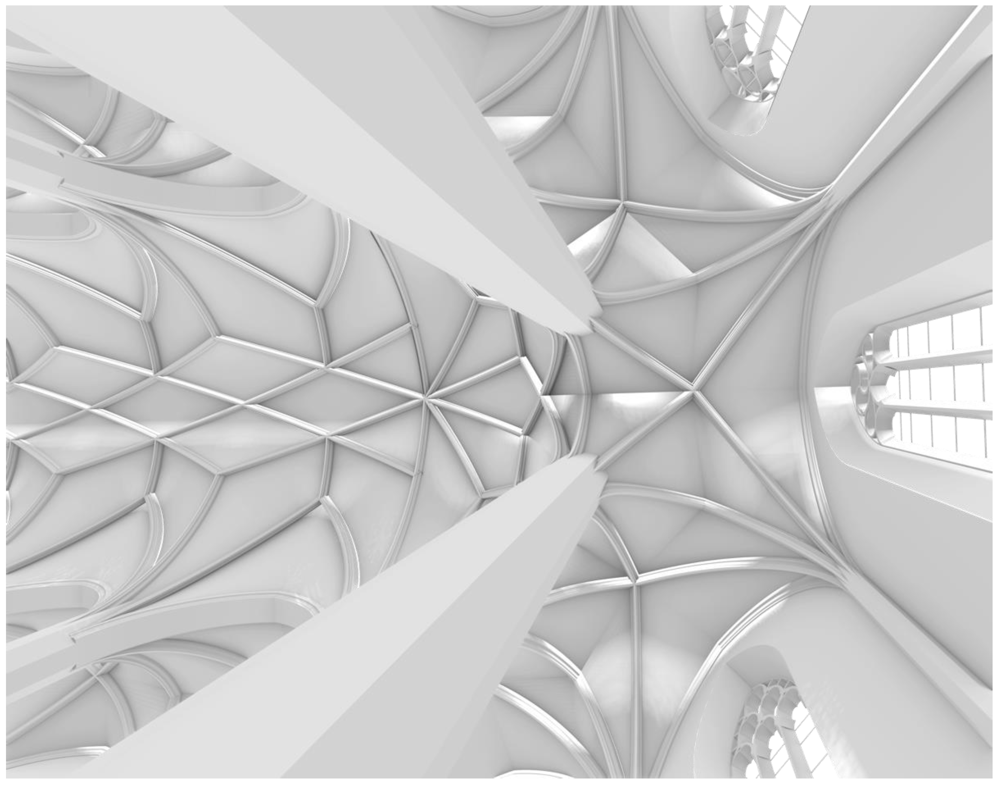
Figure 8.
Theoretical reconstruction of the vault (3D). Own drawing, 2022.

Figure 9.
Theoretical reconstruction of the stellar vault north to the former tower. Background: laser scanner survey, point cloud in the springing zone. Angles: the in situ angles of the rib fragments at the springings, lines: the hypothetical position of the original (destroyed) ribs. North is towards the right of the page.

Figure 10.
Cross-vault generation, intermediate step. Input: the rectangular bay (ABCD rectangle, horizontal plane). On the figure the AC semicircular diagonal arch can be seen in vertical plane; the construction of the arcade, transversal, and wall arches, using the same radius; and the intersection points marking the tips of these pointed arches (E, F, G, H). Own work, 2022.

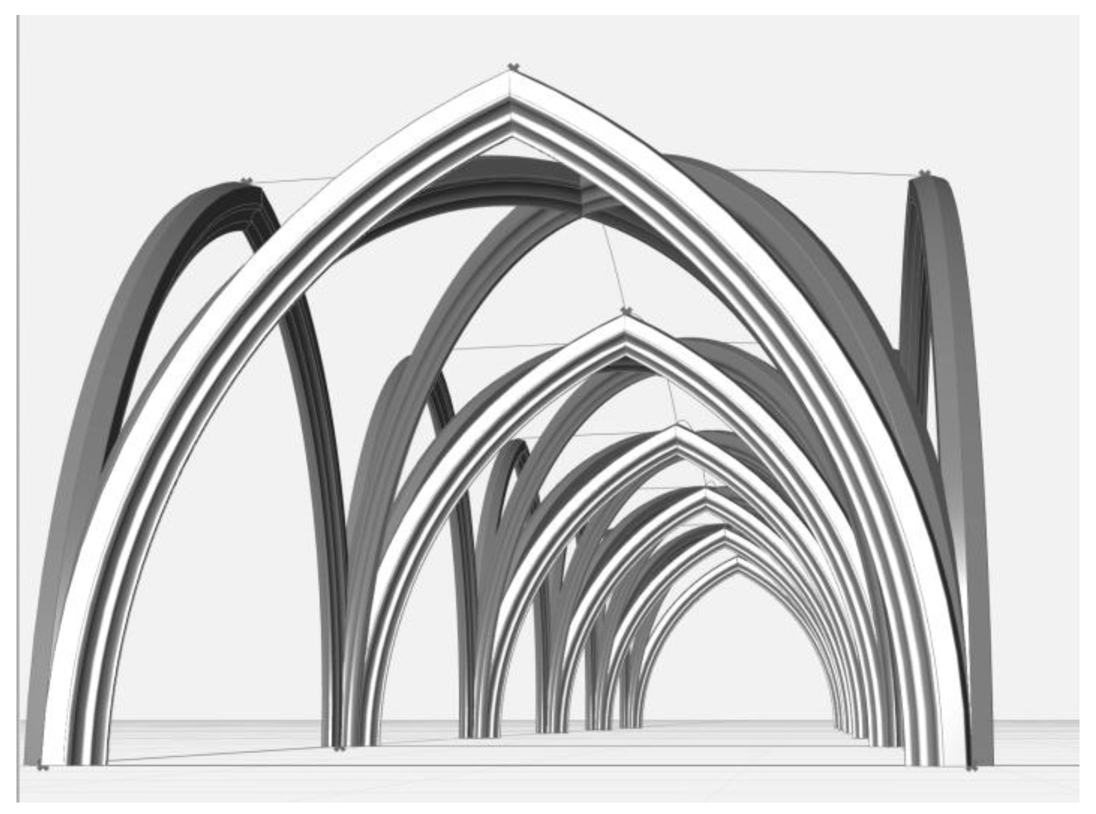
Figure 11.
The ribs of the side aisle of the Avas church, generated by algorithm. Own work, 2022.

Figure 12.
Stellar vault configurations from Hans Hammer’s portfolio, end of the 15th century. The square-shaped outline of the diagrams marks the outline of the vaulting bays, the other lines represent the axis lines of the ribs, the nodes represent the rib junctions. Source: Herzog August Bilbliothek Cod. Guelf. 114.1 extrav Fol 23v, redrawn by the author, 2020.

Figure 13.
Randomly generated stellar vault configurations. The square-shaped outline of the diagrams marks the outline of the vaulting bays, the other lines represent the axis lines of the ribs, the nodes represent the rib junctions. Own work, 2022.
Figure 13.
Randomly generated stellar vault configurations. The square-shaped outline of the diagrams marks the outline of the vaulting bays, the other lines represent the axis lines of the ribs, the nodes represent the rib junctions. Own work, 2022.

Figure 14.
Randomly generated stellar vault configurations using fixed parameters taken from the Avas church. The rectangular outline of the diagrams marks the outline of the vaulting bay, the other lines represent the axis lines of the ribs, the nodes represent the corners of the vaulting bay. Own work, 2022.

Figure 15.
Visibility graph analysis of the late medieval layout (left) and the current layout (right) of the Avas church. The visibility graph shows how visible a given point in space is from other parts of the space. Values grow with the number of spots from where the point is visible and are displayed on a heat map (red: higher values, blue: lower values). North is towards the right of the page. Own work, 2022.

Publisher’s Note: MDPI stays neutral with regard to jurisdictional claims in published maps and institutional affiliations. |
© 2022 by the author. Licensee MDPI, Basel, Switzerland. This article is an open access article distributed under the terms and conditions of the Creative Commons Attribution (CC BY) license (https://creativecommons.org/licenses/by/4.0/).
Share and Cite
MDPI and ACS Style
Bereczki, Z. Order, Procedure, and Configuration in Gothic Architecture: A Case Study of the Avas Church, Miskolc, Hungary. Architecture 2022, 2, 671-689. https://doi.org/10.3390/architecture2040036
AMA Style
Bereczki Z. Order, Procedure, and Configuration in Gothic Architecture: A Case Study of the Avas Church, Miskolc, Hungary. Architecture. 2022; 2(4):671-689. https://doi.org/10.3390/architecture2040036
Chicago/Turabian StyleBereczki, Zoltán. 2022. "Order, Procedure, and Configuration in Gothic Architecture: A Case Study of the Avas Church, Miskolc, Hungary" Architecture 2, no. 4: 671-689. https://doi.org/10.3390/architecture2040036