
Effect of Laminated Core Body Size on Motor Magnetic Properties

Department of Electrical Electronic & Computer Engineering, Gifu University, Gifu City 501-1193, Japan
Magnetism 2023, 3(2), 158-168; https://doi.org/10.3390/magnetism3020013
Submission received: 16 February 2023
/
Revised: 12 May 2023
/
Accepted: 16 May 2023
/
Published: 6 June 2023
Abstract
:The magnetic characteristics of electromagnetic steel sheets used for motors are evaluated under ideal sinusoidal excitation. However, in actual equipment driving, excitation by pulse-width modulation (PWM) waves is the mainstream method. Therefore, it is necessary to clarify how the magnetic properties used in motors are changed by sinusoidal excitation and inverter excitation. To clarify the magnetic properties of the laminated core by inverter excitation, samples with different core sizes were prepared and the effects on the magnetic properties were then investigated. The magnetic properties were measured by changing only the input voltage VDC while maintaining the carrier frequency and modulation factor constant. As the results, the iron loss values of the small, medium, and large samples with inverter excitation were 6.05, 9.58, and 11.62 W/kg, respectively. The iron losses of the small, medium, and large toroidal cores with inverter excitation increased by 124.9, 256.1, and 332.0%, respectively, compared with the iron loss of each toroidal core with sinusoidal excitation. The larger the body, the higher the required voltage and iron loss. It can be inferred that a larger amount of energy was required to excite a larger toroidal core. This was because the change in magnetic flux density per unit time of the large toroidal core was greater than that of other cores. This indicates that the large toroidal core generated larger eddy currents than other cores. Therefore, it is possible to say that large toroidal cores generate greater eddy current losses than other cores.
1. Introduction
According to IPCC reports [1,2], achieving global carbon neutrality and limiting global warming to 1.5 °C by 2050 is the key to minimizing the impacts of climate change on society. As part of the Paris Agreement, many countries are developing plans to prevent climate change, known as nationally determined contributions (NDCs), to quickly reach global peaks in greenhouse gas emissions. To reach this goal, it requires the transition to carbon-free energy systems by the mid-century through the large-scale uptake of clean energy and innovative technologies, energy efficient equipment, and renewable energy. Countries will begin by estimating emission reduction pathways to meet their climate goals and build action plans to achieve the proposed targets. The European Commission announced its objective to steer its economy and society towards a more sustainable and environmentally friendly pathway in 2019 [3], while in 2021, it set out a roadmap to achieve climate neutrality by 2050, including the intermediate target of at least a 55% net reduction of greenhouse gas (GHG) emissions by 2030 [4].
On the other hand, modern society requires a large amount of energy, particularly clean and highly adaptable electrical energy. The biggest electricity consumers are motors, which have an electricity usage rate of over 57.3% [5,6,7]. Motor has industrial, commercial, and household applications owing to their high efficiency and convenience. Therefore, an increase in motor efficiency leads to huge electrical energy savings realized in Negawatts [8,9,10]. To improve the efficiency of the motor, it is therefore necessary to understand the magnetic characteristics of the motor close to the actual driving environment [10,11,12,13,14,15]. Universally, power electronics accomplish power conversions involving the bidirectional flow of energy between sources, storage, and distribution grids. In such processes, using IGBT, SiC, and GaN semiconductors have enabled power conversion electronics and motor controllers to operate at high frequencies. Soft magnetic materials for inductors, transformers, and electrical machines have often been overlooked, but they have been considered important in worldwide energy conversions. In general, when driving a motor, excitation with a PWM inverter is used to provide an arbitrary frequency or voltage [16,17,18,19,20,21,22,23,24,25].
On the other hand, minor loops are created in the hysteresis curve by the on-off operation of the inverter control, which increases iron loss. Although studies have been conducted on motor magnetic properties using inverter excitation, the effect of the motor core size remains unclear. In general, in the case of sinusoidal excitation, the size of the sample to be measured does not affect the measurement if the material is the same. This is because the excitation current waveform is controlled so that the magnetic flux density obtained by time-integrating the induced voltage on the secondary side becomes a sine wave. However, in the case of inverter excitation, the waveform of the excitation current is not controlled unlike the sine wave excitation, and therefore the resulting output waveform is distorted. In the previous report, our group conducted experiments considering changes in body size or number of turns of the toroidal core, and experiments were conducted through simultaneously changing the core size and the number of turns. However, it was difficult to provide deep consideration to the iron loss increments due to changes in the physical size of the sample, and only the results of the experiment have been reported [16,17,18].
In this study, the effect of the body size on the magnetic properties under sinusoidal excitation and inverter excitation were investigated, while the cross-sectional area and number of turns of the laminated core were kept constant. This clarifies the reason for why loss varies with core size.
2. Experimental Procedure
2.1. Toroidal Core Samples
Non-oriented electrical steel sheets (35H270, Nippon steel) were wire cut, and 10 sheets, with a total thickness of 3.5 mm, were laminated as the toroidal core to be measured. Type 2 polyester copper wire (2PEW), with a diameter of 0.45 mm for the exciting coil and 0.20 mm for the detection coil, was used for the windings. Furthermore, a Bakelite frame was used to prevent stress from the windings. Measurements were performed using a toroidal core in which the cross-sectional area and number of turns were kept constant, and only the magnetic path length was changed (as shown in Table 1).
2.2. Measurement System
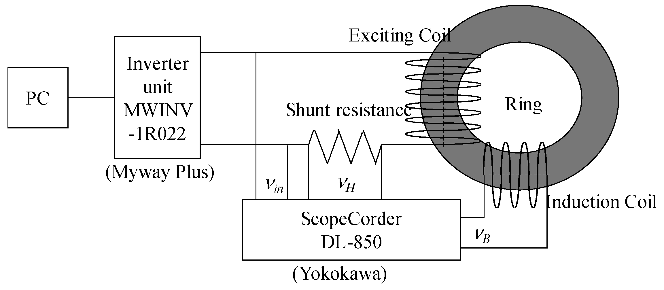
Figure 1 shows the measurement system used for the inverter excitation. NWINV-1R022 (Myway Plus) was used as the PWM inverter and DL850 (Yokogawa Electric Corporation, Tokyo, Japan) was used as the waveform recording device. The PWM voltage was generated by the inverter, and a magnetic field was then generated by the exciting coil. The magnetic-field strength was calculated from the current of the exciting coil, as shown in Equation (1). The magnetic flux density was obtained by integrating the induced voltage measured from the detection coil over time, as shown in Equation (2):
where N1 is the number of turns of the exciting coil, N2 is the number of turns of the induction coil, L is the magnetic path length of the toroidal core, VH is the measured voltage of the shunt resistance, VB is the measured voltage of the induction coil, R is the shunt resistance, and S is the cross-sectional area of the toroidal core.
The carrier frequency was fixed at 10 kHz and the modulation factor was fixed at 0.6. The input voltage (VDC) of the inverter was adjusted to maintain a constant magnetic flux density. The shunt resistance (R10000, Alpha Electronics, Akita, Japan) was 1 Ω.
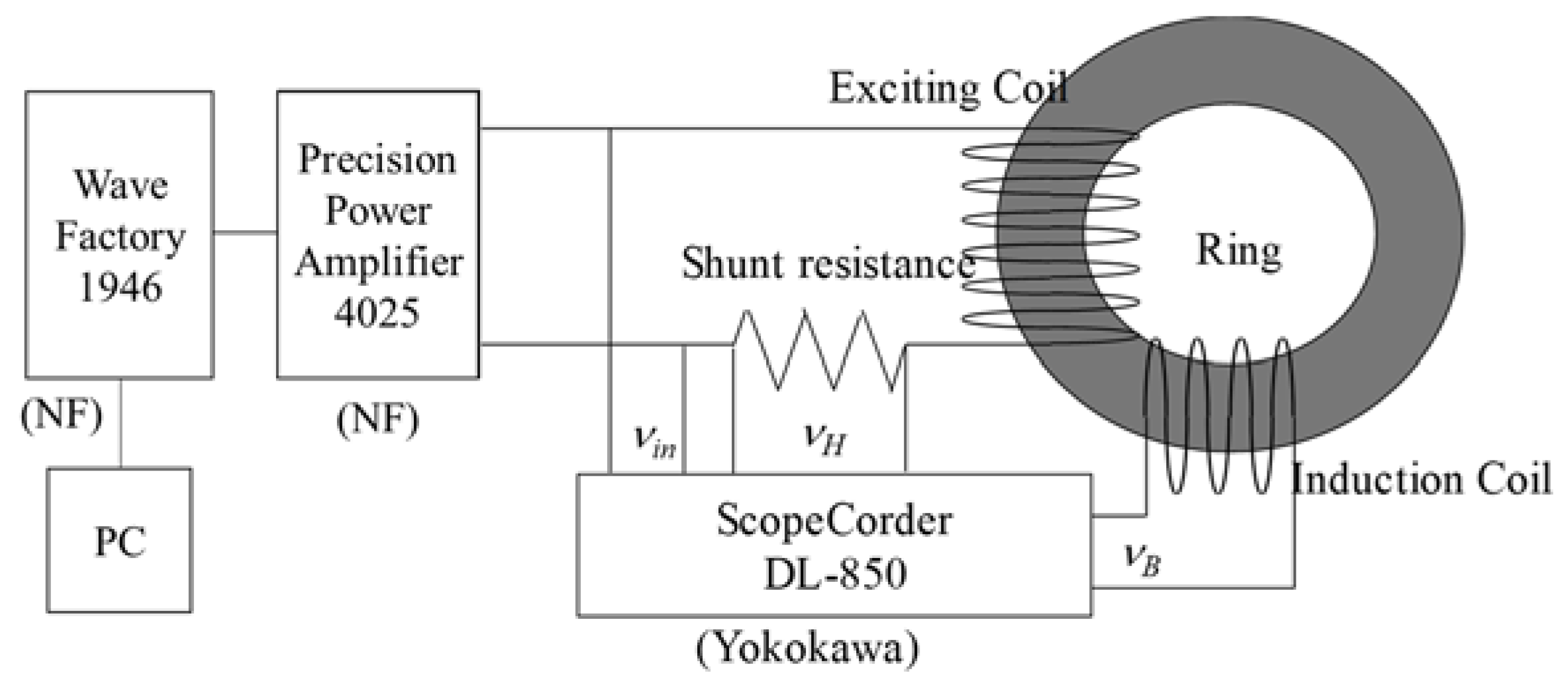
The measurement system used for sinusoidal excitation is shown in Figure 2. The WAVE FACTORY 1946 (NF, Kanagawa, Japan) was used as the oscillator, 4025 (NF, Kanagawa, Japan) was used as the amplifier, and DL750 (Yokogawa Electric Corporation, Tokyo, Japan) was used as the waveform recording device. Experiments were conducted with a fundamental frequency of 50 Hz and a maximum magnetic flux density of 1.5 T as the common input conditions for inverter excitation and sinusoidal excitation, respectively. To generate a sinusoidal waveform of a high magnetic flux density, it is necessary to use a distorted excitation waveform.
With the magnetic field and magnetic flux density obtained from Equations (1) and (2), the iron loss, WFe, was calculated from Equation (3):
where f0 is the basic frequency, and ρ is the density of the electrical steel sheet. There are various methods for finding the internal area of the B-H curve. This time, the unit area (rectangular area) was obtained by multiplying the amount of change in the magnetic flux density by the magnitude of the magnetic field. The internal area of the B-H curve was derived by accumulating the unit area for one cycle. After that, the iron loss per unit mass (W/kg) was obtained by multiplying by the fundamental frequency and dividing by the density of the electrical steel sheet.
A general method for iron loss separation is the two-frequency method. In this method, the amount of eddy current increase may or may not be proportional to the square of the frequency depending on the material. DC hysteresis loss generally increases in proportion to frequency. Therefore, the iron loss separation was performed from the difference between the DC hysteresis loss obtained from the DC measurement, and the AC hysteresis loss obtained from the AC measurement.
To compare the magnetic flux density waveforms of sinusoidal excitation and inverter excitation, form factor and total harmonic distortion (THD) were used.
3. Results and Discussion
3.1. Magnetic Properties
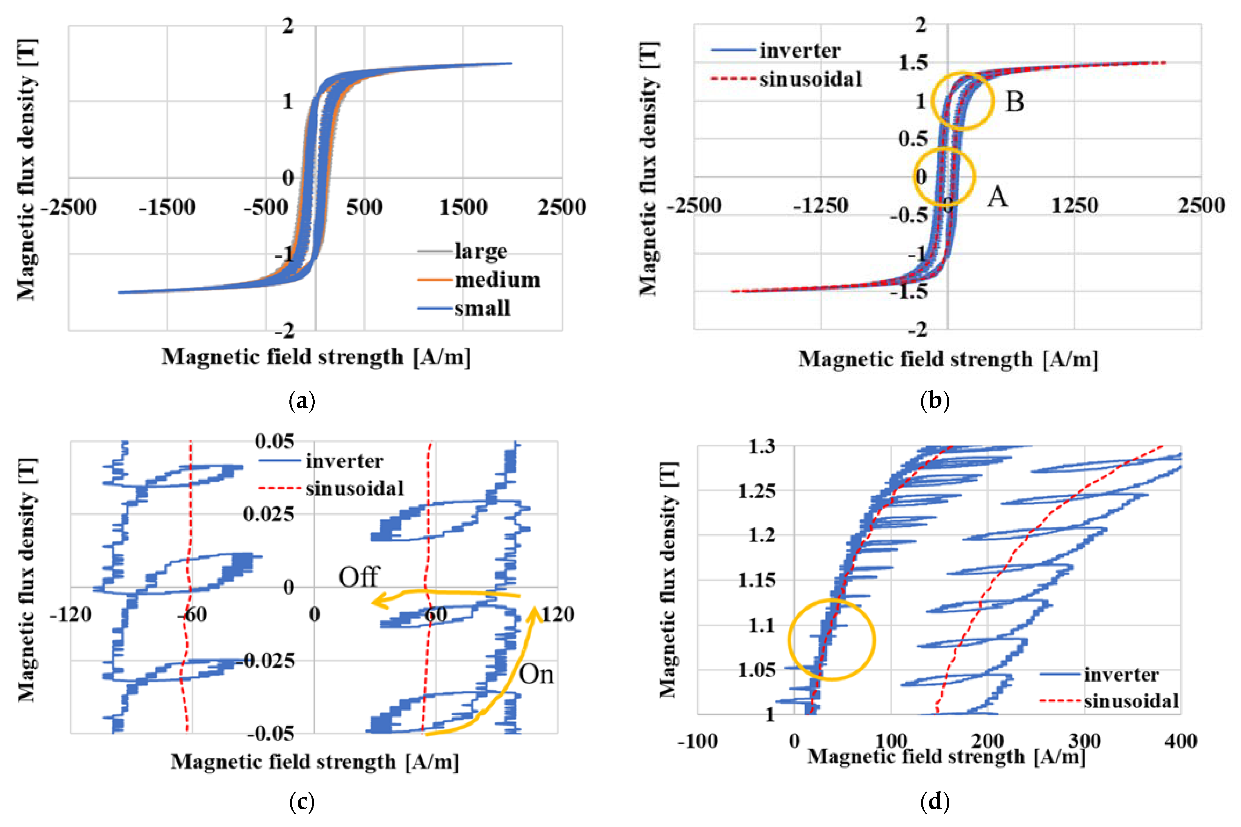
The magnetic properties obtained by sinusoidal excitation with B waveform control were found to be constant regardless of the size of the toroidal core. The iron loss of each toroidal core with sinusoidal excitation was approximately 2.69 W/kg. Figure 3a shows the magnetic hysteresis curves of each toroidal core with inverter excitation. The iron loss values of small, medium, and large samples with inverter excitation were 6.05, 9.58, and 11.62 W/kg, respectively. The iron losses of the small, medium, and large toroidal cores with inverter excitation increased by 124.9, 256.1, and 332.0%, respectively, compared with the iron loss of each toroidal core with sinusoidal excitation. Iron loss was found to be proportional to the area of the hysteresis curve, which varies greatly with the width. Figure 3b represents magnetic hysteresis curves of the small core with inverter excitation and sinusoidal excitation. The hysteresis curve of sinusoidal excitation was formed inside the hysteresis curve of inverter excitation. Parts A and B were enlarged as the hysteresis curve of the inverter excitation was difficult to understand. The enlarged magnetic hysteresis curve of area A is shown in Figure 3c. Generally, minor loops (closed loops) were found to have appeared. The existence of the ON-voltage generated by means of the switching operation of the power semiconductors in the inverter was examined. When the switch is on, the voltage of the load is almost the same voltage as the input DC voltage of the inverter as the voltage of the switch is small. Then, when the switch on the low-side of the inverter is off, the current flows into the diode on the high-side of inverter. In this time, the load (toroidal core) was affected by the ON-voltage, which is the sum of the switch voltage and the diode voltage, thereby making the minor loop. The reason why the size of the minor loop was different depends on the circuit of the inverter. The enlarged magnetic hysteresis curve of area B is represented in Figure 3d. There was no minor loop observed in the circled area, which is typically a phenomenon that occurs at the portion where the positive voltage is switched to the negative voltage. At this time, the input voltage of the inverter was too low to operate the semiconductor device [19,20].
In the case of sinusoidal excitation, the form factor was controlled to 1.11 and the distortion factor to 1% or less. In the case of inverter excitation, the form factors of the small, medium, and large samples were 1.09, 1.07, and 1.06, respectively, and THD were 14.6%, 18.1%, and 20.2%, respectively. The form factor and distortion factor were degraded by the larger core, and iron loss was also found to have increased. This clarifies that the higher the core size, the higher the harmonic content.
3.2. Major Loops
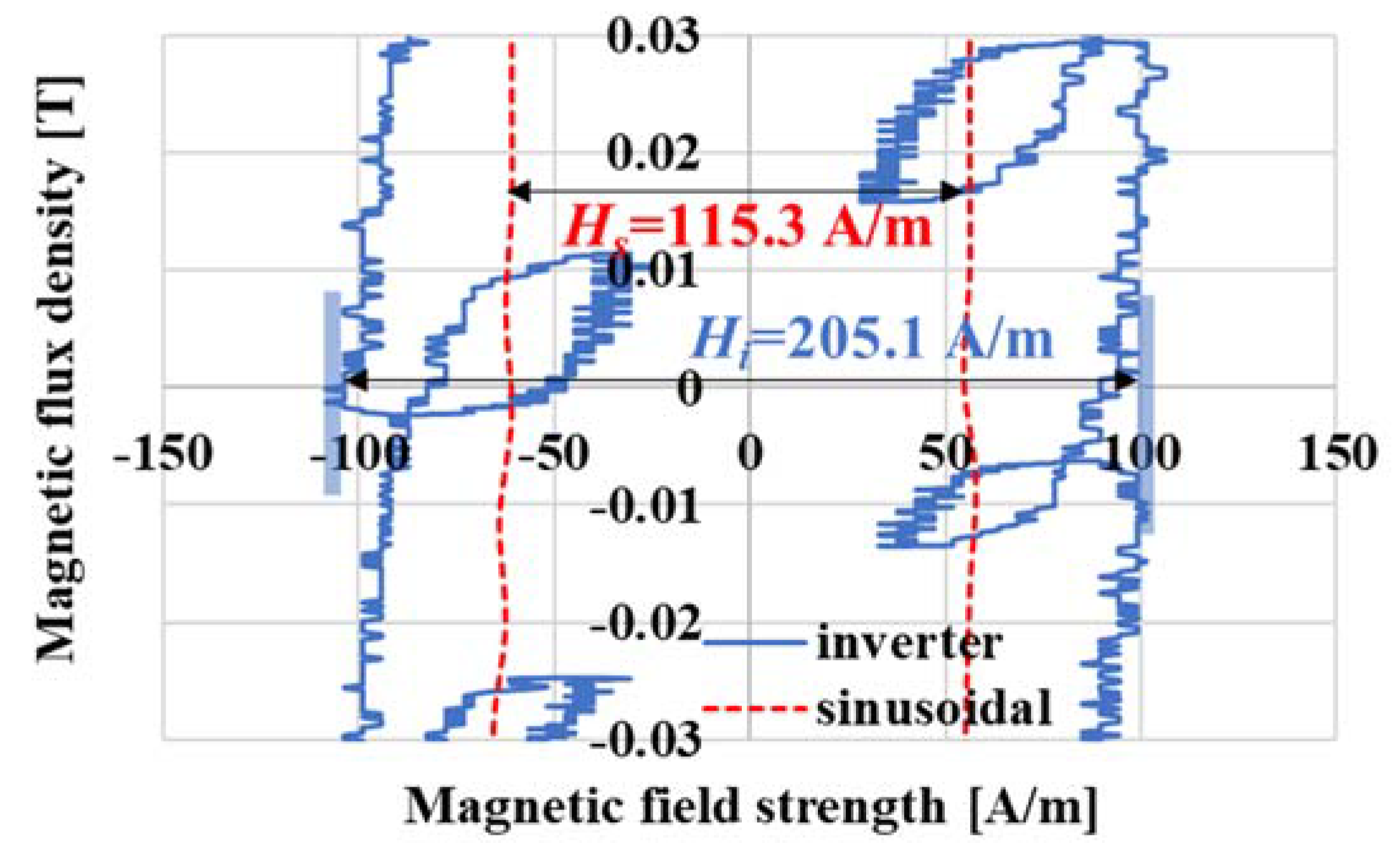
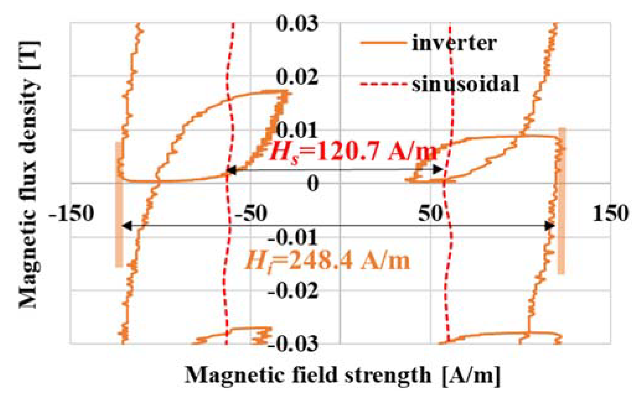
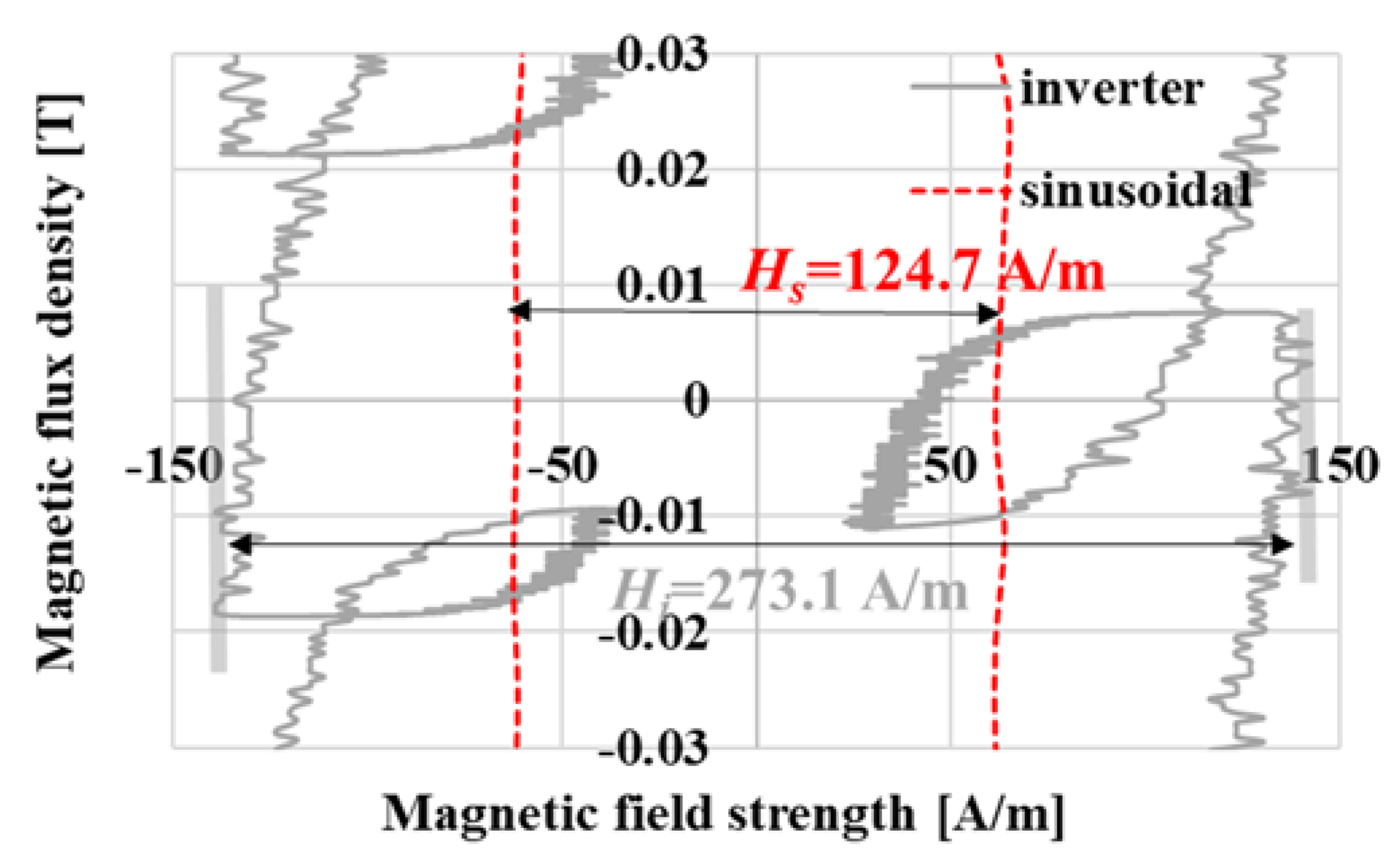
Since it is difficult to compare the body size differences in the major loop only, enlarged views around B = 0 [T] are shown in Figure 4, Figure 5 and Figure 6. Comparison items are necessary to analyze the magnetic properties of each excitation method. To compare the major loops with the sinusoidal and inverter excitation methods, it is necessary to define the width of the major loop. For the magnetic hysteresis curves obtained using inverter excitation, the major loop width is the largest value of the magnetic field at each minor loop. Hs and Hi are the widths of the major loop at 0 T when using the sinusoidal and inverter excitation methods, respectively [20].
The major loop widths with sinusoidal excitation are 115.3, 120.7, and 124.7 A/m, respectively. From Figure 4, Figure 5 and Figure 6, the Hi of the small, medium, and large toroidal cores was 205.1, 248.4, and 273.1 A/m, respectively. The major loop widths of the small, medium, and large toroidal cores with inverter excitation increased by 77.5, 105.8, and 120.2%, respectively, compared with the major loop widths of each toroidal core with sinusoidal excitation. The rate of iron loss was much larger than the rate of width increment. Therefore, the major loop width was found to not be the only reason for the increase in iron loss.
3.3. Minor Loops
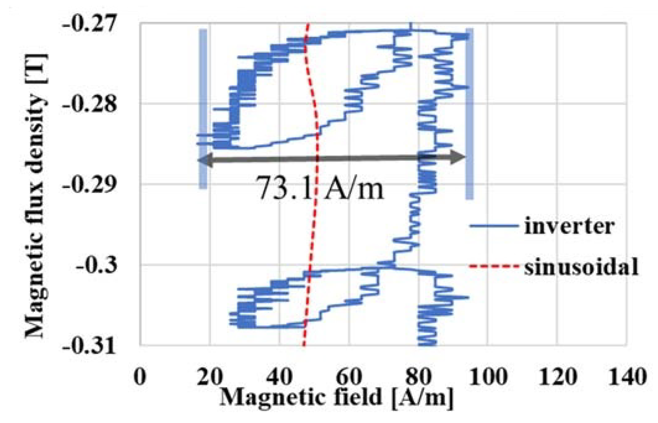
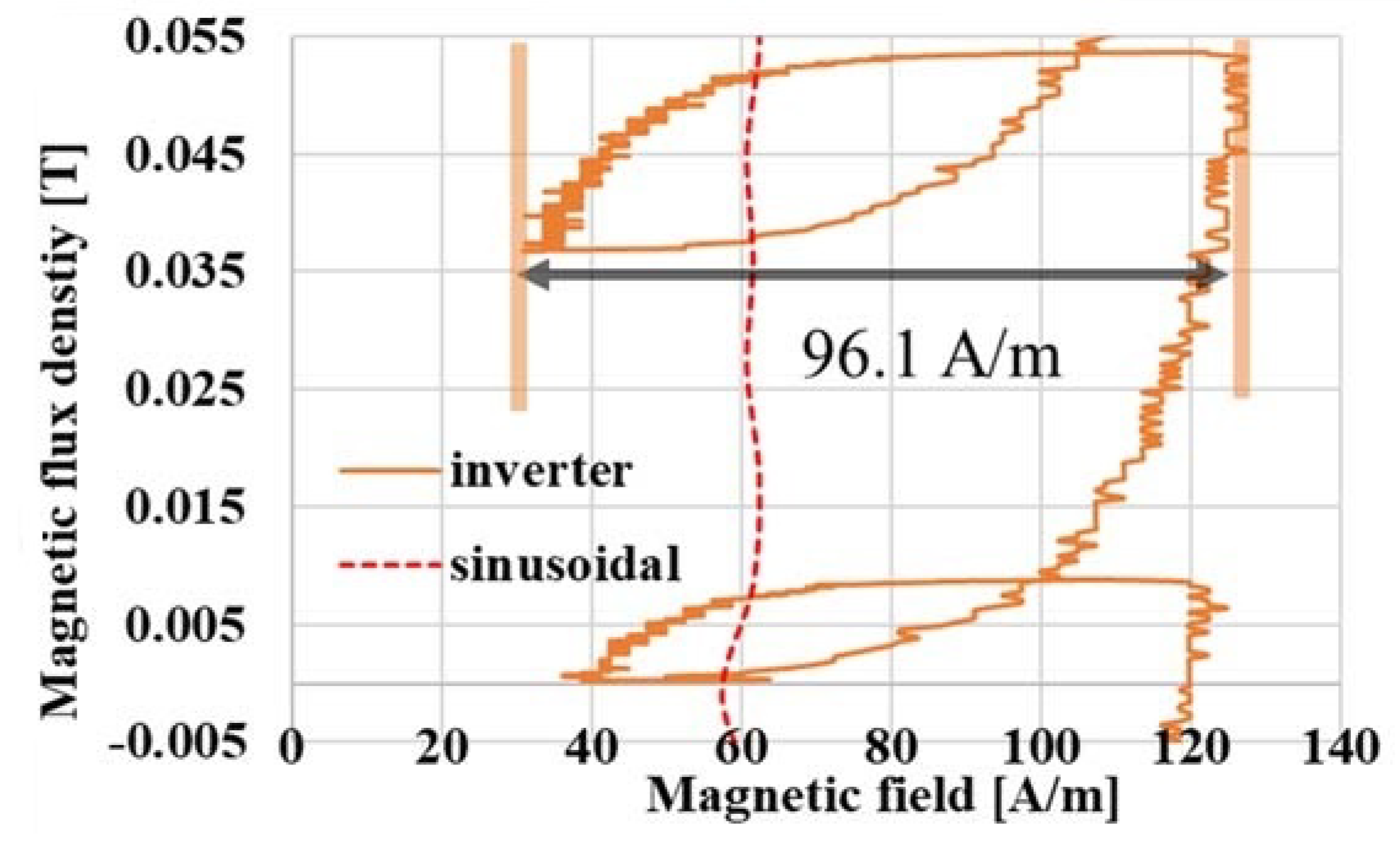
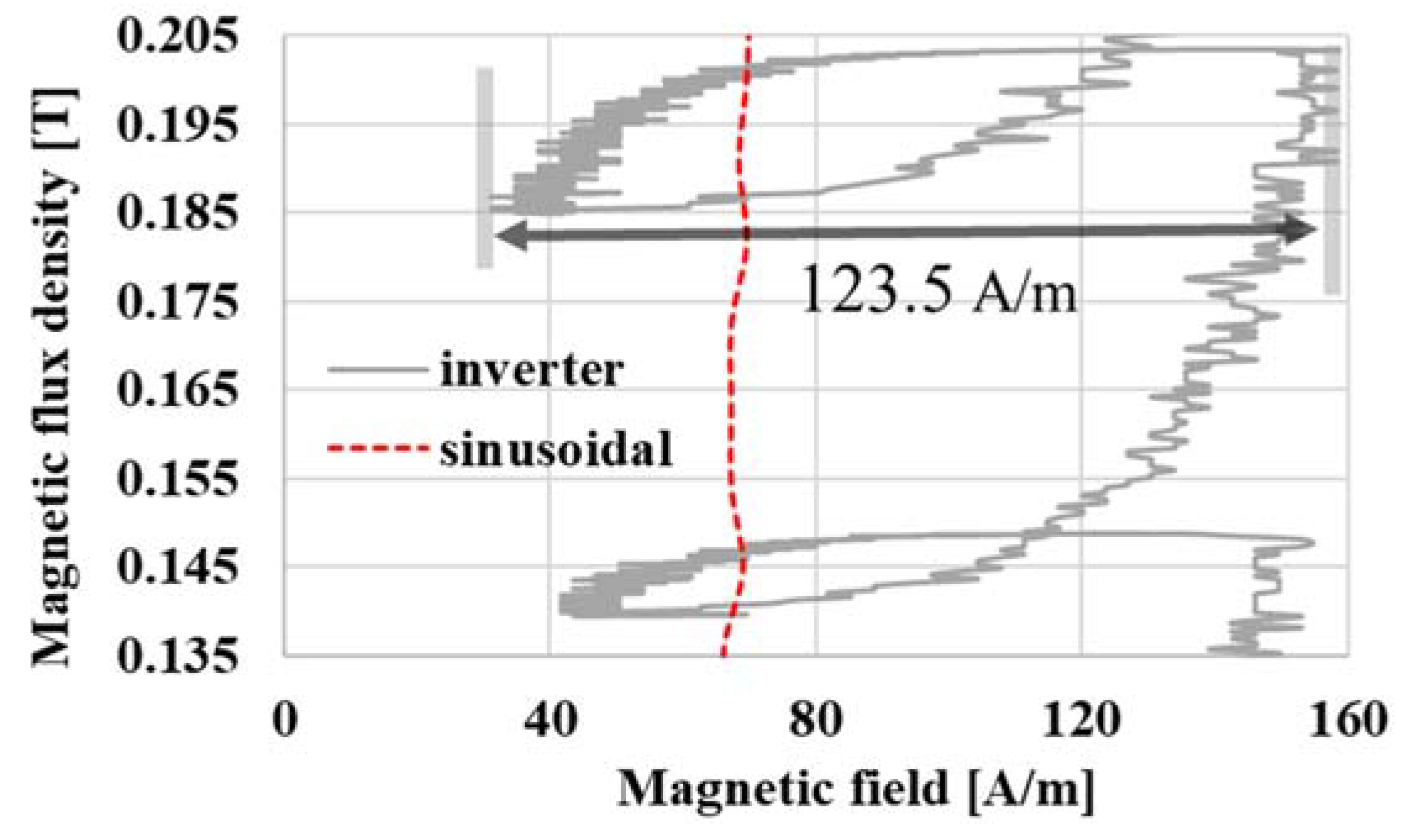
Another factor for the iron loss increment is the increment of the minor loop width. Minor loops are made by inverter excitation. This minor loop is a factor that increases iron loss by being double integrated. By measuring the width of the minor loop, the increasing double integral value can be found [20]. Figure 7, Figure 8 and Figure 9 show the minor loops of each toroidal core. As shown in the red rectangular in Figure 10, a minor loop of each core was observed when the time to switch the PWM waveform from negative to positive due to inverter excitation was aligned. The magnetic flux density of each loop had a different magnetic level; however, each sample was in the same time zone. The reason why the magnetic flux density values of each minor loop are different was explained later with red rectangular area (Figure 10, Figure 11, Figure 12 and Figure 13). The minor loop extended to the inner and outer sides of the sinusoidal curve.
The minor loop widths of the small, medium, and large toroidal cores with inverter excitation increased by 73.1, 96.1, and 123.5 A/m, respectively. The minor loop width increased by 31.5% and 40.8% in medium and large toroidal cores, respectively, compared to the small toroidal core.
3.4. dB/dt Waveform Analysis
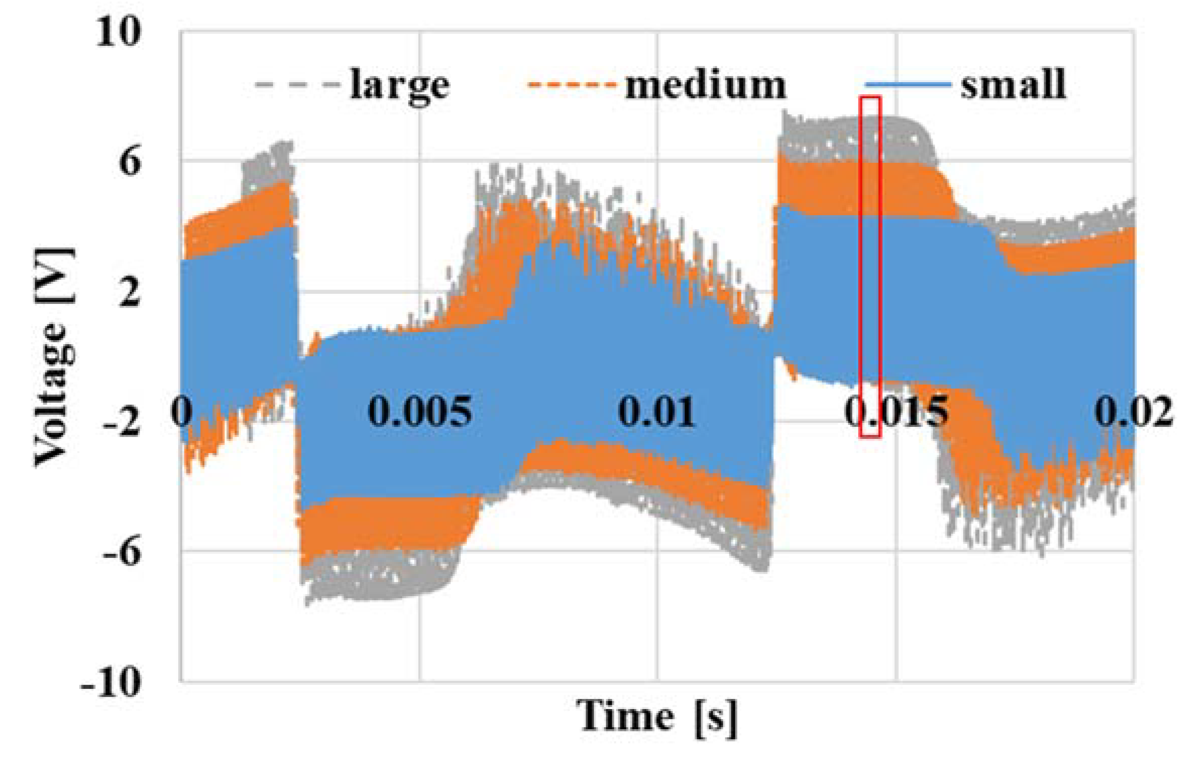
In Maxwell’s equations, rot E is −∂B/∂t. This means that the eddy current generated in the magnetic material is determined by the amount of change in magnetic flux density per unit time. Therefore, dB/dt changing per unit time in each core were investigated. dB/dt waveforms of each toroidal core are shown in Figure 10. The red rectangular area represents the dB/dt of minor loops at the same period in Figure 7, Figure 8 and Figure 9. From Equation (1), the induction coil voltage (VB) is the time derivative of the magnetic flux density (dB/dt). The dB/dt waveform was divided into positive and negative parts. At this time, the starting point of the dB/dt waveform switched from positive to negative. The large toroidal core showed the highest voltage.
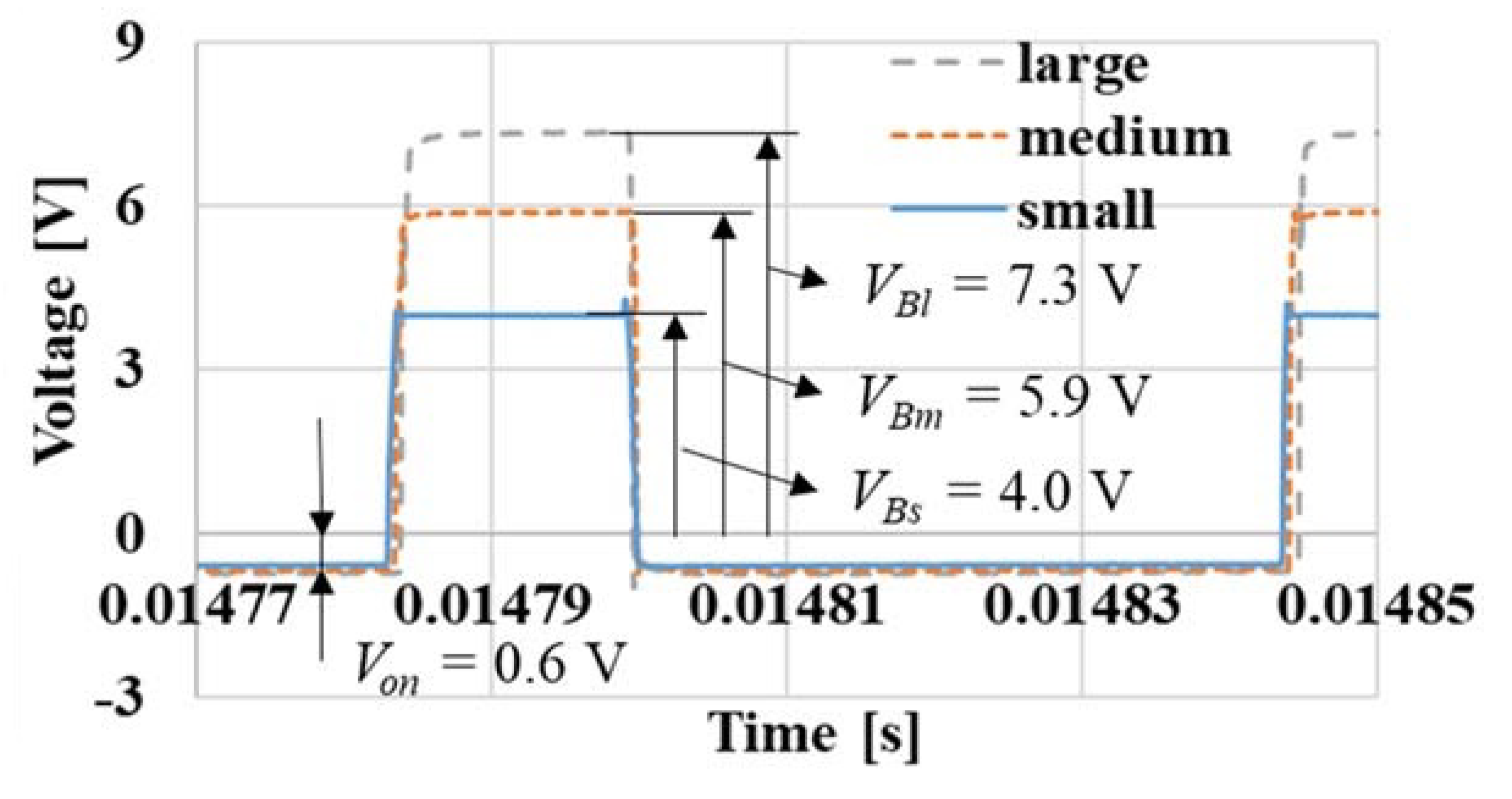
Figure 11 shows an enlarged dB/dt waveform for each toroidal core. Since the number of turns was the same and the physical size was larger, a large voltage was therefore required to achieve the same magnetic flux density (1.5 T). Therefore, the VB was increased with a larger toroidal core. The ON-voltage of each toroidal core was around 0.6 V [19]. The VB of the small, medium, and large toroidal cores were 4.0, 5.9, and 7.3 V, respectively. A large VB implies that the change in magnetic flux density is large, and that the generated eddy current loss is large. The reason for this has not yet been clarified, but it can be inferred that a larger amount of energy is necessary to excite a larger toroidal core. Therefore, a large toroidal core has a large dB/dt and a large eddy current. The reason for this is that, in sinusoidal excitation, waveform control is performed to make the output waveform of the magnetic flux density a sine wave, but in inverter excitation, waveform control is not performed. Therefore, the B and dB/dt waveforms differed with body size. Another possible factor was changes in the inductance and reactance of the exciting coil. As the core size increases, the magnetic path length also increases, resulting in the inductance and reactance of the excitation coil decreasing. The inductance of the small, medium, and large toroidal cores was 1.69, 0.89, and 0.62 mH, respectively. The inductance at 50 Hz of the small, medium, and large toroidal cores was 0.53, 0.28, and 0.20 Ω, respectively. The magnetic field was determined by the amount of current applied to the excitation coil. It was deemed necessary to decrease the output voltage of the inverter in order to obtain the same magnetic flux density in a large core. However, since the applied voltage was increased, it can be said that the influence of the decrease in the reactance due to the increase in the magnetic path length was small. Another possible factor was changes in the cutoff frequency. The circuit was a RL low-pass filter for the current. Therefore, in the case of a large core, as the reactance decreases, the cutoff frequency increases, so the amount of attenuation of high frequency components decreases. In this study, the cutoff frequency of the simple RL circuit of the large core was calculated. However, it turned out that it was not a simple circuit as the cutoff frequency of the large core was 0.8 Hz. This should therefore be considered in the future.
3.5. B Waveform Analysis
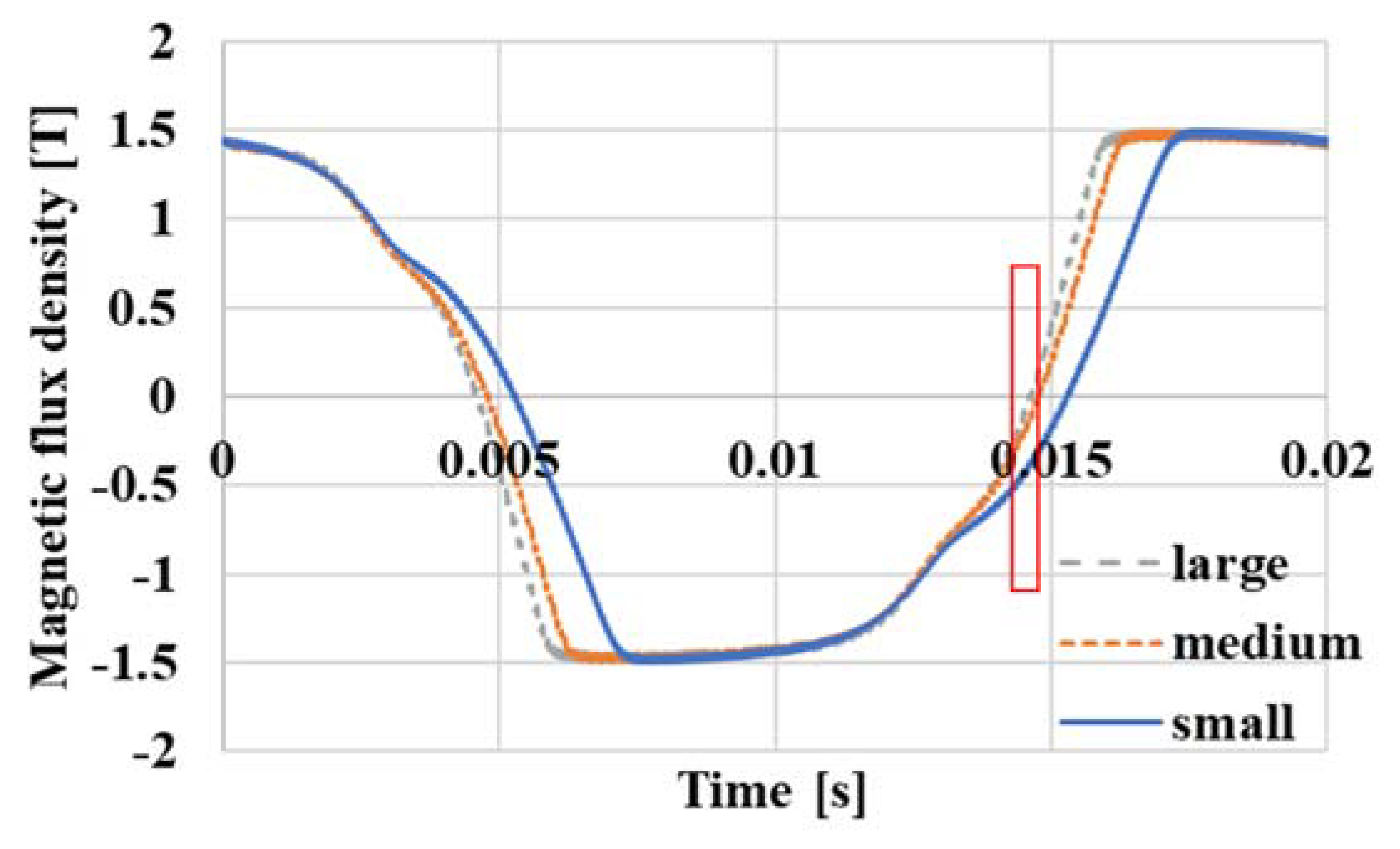
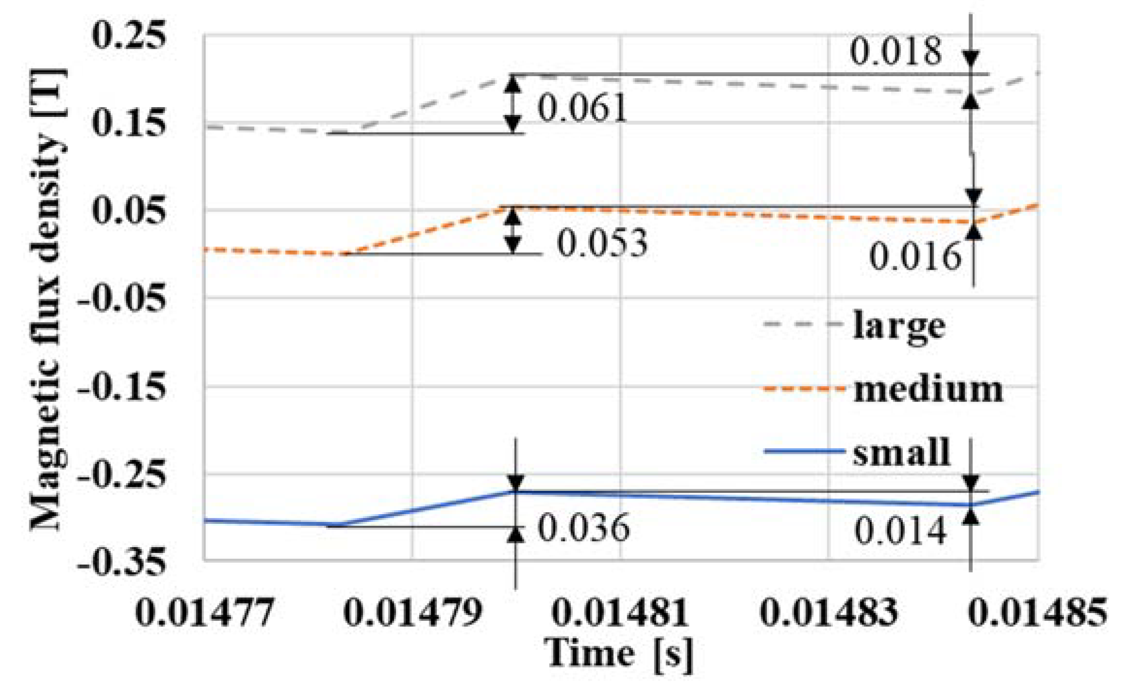
Figure 12 shows the B waveform of each toroidal core. The red rectangular area is the same time period of dB/dt as shown in Figure 10. This B waveform was obtained by time-integrating the dB/dt waveform of Figure 10. As mentioned above, it can be confirmed that the change in the magnetic flux density of the large toroidal core was greater than that of the other toroidal cores. As a result, the time to reach 1.5 T from −1.5 T was the shortest for the large toroidal core. This implied that the generated eddy current loss was large.
An enlarged B waveform of each toroidal core is shown in Figure 13. The increments in the magnetic flux densities of the small, medium, and large toroidal cores were 0.036, 0.053, and 0.061 T, respectively. This was because B is the integral of VB, as mentioned above.
What are the possible reasons for the increase in iron loss? That is the reason why the fluctuation amount of the magnetic flux density increases was as follows. Since the number of turns was the same and the physical size was larger, a large voltage was therefore required to achieve the same magnetic flux density (1.5 T). Also, although the number of turns is the same, if the physical size was increased, the magnetic path length would also increase, meaning the inductance of the excitation coil would decrease as a result. In addition, as the physique increased, the form factor decreased from 1.11, with the distortion factor increasing at the same time. While all of this influences the iron loss increase, further experiments are necessary to quantitatively determine which factors have the greatest influence. The biggest factor is that the larger the physique needs, the larger the amount of DC voltage in the inverter, which makes the dB/dt larger as a result.
4. Conclusions
The effect of laminated toroidal motor core size was measured by changing only the input voltage VDC, while keeping the carrier frequency and modulation degree constant. As for the results, the width of the magnetic hysteresis curve of the small, medium, and large toroidal cores with inverter excitation was 205.1, 248.4, and 273.1 A/m, respectively, and the minor loop widths of the small, medium, and large toroidal cores with inverter excitation increased by 73.1, 96.1, and 123.5 A/m, respectively. The iron loss values of the small, medium, and large samples with inverter excitation were 6.05, 9.58, and 11.62 W/kg, respectively. The iron losses of the small, medium, and large toroidal cores with inverter excitation increased by 124.9, 256.1, and 332.0%, respectively, compared with the iron loss of each toroidal core with sinusoidal excitation. These findings signify how the larger the body, the higher the required voltage and iron loss. It can be inferred that a larger amount of energy was required to excite a larger toroidal core. This was because the change in magnetic flux density per unit time of the large toroidal core was found to be greater than that of other cores. This indicates that the large toroidal core generates larger eddy currents than other cores. Therefore, it is possible to say that large toroidal cores generate greater eddy current losses than other cores.
Funding
This research received no external funding.
Institutional Review Board Statement
Not applicable.
Informed Consent Statement
Not applicable.
Data Availability Statement
Data available in a publicly accessible repository.
Acknowledgments
The author is grateful to Patrick Cassidy (an adjunct instructor of Gifu University) for proofreading.
Conflicts of Interest
The author declares no conflict of interest.
References
- IPCC Climate Change 2022: Impacts, Adaptation, and Vulnerability. Contribution of Working Group II to the Sixth Assessment Report of the Intergovernmental Panel on Climate Change. 2022. Available online: https://www.ipcc.ch/report/ar6/wg2/ (accessed on 20 April 2023).
- IPCC Climate Change 2022: Mitigation of Climate Change. Contribution of Working Group III to the Sixth Assessment Report of the Intergovernmental Panel on Climate Change. 2022. Available online: https://www.ipcc.ch/report/ar6/wg3/ (accessed on 20 April 2023).
- European Commission. 2030 Climate Target Plan. 2020. Available online: https://climate.ec.europa.eu/eu-action/european-green-deal/2030-climate-target-plan_en (accessed on 20 April 2023).
- European Commission. 2050 Long-Term Strategy. 2021. Available online: https://climate.ec.europa.eu/eu-action/climate-strategies-targets/2050-long-term-strategy_en (accessed on 20 April 2023).
- Fuji Keizai Group. The Pulse-Taking of the Near Future and the Present Conditions about the Amount of Use Electricity of the Electricity Usage Apparatus; Fuji Keizai: Tokyo, Japan, 2009; pp. 1–53. (In Japanese) [Google Scholar]
- The Agency of Natural Resource and Energy. Japan’s Energy White Paper; Energy Forum: Tokyo, Japan, 2012; p. 88. (In Japanese)
- IEA. World Energy Outlook 2017; IEA Publications: Paris, France, 2017.
- Croucher, M. Energy efficiency: Is re-distribution worth the gains? Energy Policy 2012, 45, 304–307. [Google Scholar] [CrossRef]
- Pop, I.G.; Văduva, S.; Talpoș, M.-F. Energetic Sustainability and the Environment: A Transdisciplinary, Economic–Ecological Approach. Sustainability 2017, 9, 873. [Google Scholar] [CrossRef] [Green Version]
- Dutil, Y.; Rousse, D. Energy Costs of Energy Savings in Buildings: A Review. Sustainability 2012, 4, 1711–1732. [Google Scholar] [CrossRef] [Green Version]
- Yang, S.-H.; Pyo, H.-J.; Jung, D.-H.; Kim, W.-H. A Study on Optimal Design Process of Dual Rotor Axial-Flux Permanent Magnet Synchronous Motors. Machines 2023, 11, 445. [Google Scholar] [CrossRef]
- Deepak, K.; Frikha, M.A.; Benômar, Y.; El Baghdadi, M.; Hegazy, O. In-Wheel Motor Drive Systems for Electric Vehicles: State of the Art, Challenges, and Future Trends. Energies 2023, 16, 3121. [Google Scholar] [CrossRef]
- Li, X.; Sun, Z.; Sun, W.; Guo, L.; Wang, H. Design of Permanent Magnet-Assisted Synchronous Reluctance Motor with Low Torque Ripple. World Electr. Veh. J. 2023, 14, 82. [Google Scholar] [CrossRef]
- Paramonov, A.; Oshurbekov, S.; Kazakbaev, V.; Prakht, V.; Dmitrievskii, V. Investigation of the Effect of the Voltage Drop and Cable Length on the Success of Starting the Line-Start Permanent Magnet Motor in the Drive of a Centrifugal Pump Unit. Mathematics 2023, 11, 646. [Google Scholar] [CrossRef]
- Bian, Y.; Wen, X.; Fan, T.; Li, H.; Liu, Z. Data-Driven-Model-Based Full-Region Optimal Mapping Method of Permanent Magnet Synchronous Motors in Wide Temperature Range. Machines 2023, 11, 324. [Google Scholar] [CrossRef]
- Yun, K.; Eguchi, S. Magnetic Properties of Different Core Size with Inverter Excitation. IEEJ MAG-19-032 2019, 32, 31–34. (In Japanese) [Google Scholar]
- Yun, K.; Eguchi, S. Magnetic Properties of Different Core Size with Inverter Excitation—Part 2. IEEJ MAG-19-160 2019, 32, 13–15. (In Japanese) [Google Scholar]
- Asai, Y.; Yun, K. Influence of Different Core Size on Magnetic Properties. IEEJ MAG-21-055 2021, 32, 5–8. (In Japanese) [Google Scholar]
- Yun, K.; Fujisaki, K. Iron Loss Characteristics of Estimated On-Voltage of Power Semiconductor by PWM Shaped Voltage Excitation. IEEJ Trans. Fundam. Mater. 2015, 135, 605–610. [Google Scholar] [CrossRef]
- Yun, K. Magnetic Properties of Electrical Steel Sheets with Motor Control Excitation. J. Electron. Mater. 2019, 48, 1472–1479. [Google Scholar] [CrossRef]
- Fernandez, M.; Robles, E.; Aretxabaleta, I.; Kortabarria, I.; Martín, J.L. Proposal of Hybrid Discontinuous PWM Technique for Five-Phase Inverters under Open-Phase Fault Operation. Machines 2023, 11, 404. [Google Scholar] [CrossRef]
- Lin, H.; Xu, J. Performance Evaluation of SiC-Based Two-Level VSIs with Generalized Carrier-Based PWM Strategies in Motor Drive Applications. Electronics 2022, 11, 4136. [Google Scholar] [CrossRef]
- Thao, N.G.M.; Zhong, S.; Fujisaki, K.; Iwamoto, F.; Kimura, T.; Yamada, T. Experimental Assessment of Motor Core Loss, Inverter Loss and Ringing Phenomenon Under SiC-MOSFET Inverter Excitation. In Proceedings of the 2019 IEEE International Electric Machines & Drives Conference (IEMDC), San Diego, CA, USA, 12–15 May 2019; pp. 1634–1640. [Google Scholar] [CrossRef]
- Ibrahim, I.; Silva, R.; Mohammadi, M.H.; Ghorbanian, V.; Lowther, D.A. Surrogate Models for Design and Optimization of Inverter-Fed Synchronous Motor Drives. IEEE Trans. Magn. 2021, 57, 8203805. [Google Scholar] [CrossRef]
- Mecke, R. Multilevel Inverter with New Wide-Bandgap SiC and GaN Power Switches. In Proceedings of the 2021 IEEE 15th International Conference on Compatibility, Power Electronics and Power Engineering (CPE-POWERENG), Florence, Italy, 14–16 July 2021; pp. 1–6. [Google Scholar] [CrossRef]
Figure 1.
Measurement system of inverter excitation.

Figure 2.
Measurement system of sinusoidal excitation.

Figure 3.
Magnetic hysteresis curves: (a) magnetic hysteresis curves of each core with inverter excitation; (b) magnetic hysteresis curves of small core with inverter excitation and sinusoidal excitation; (c) enlarged magnetic hysteresis curve of area A; and (d) enlarged magnetic hysteresis curve of area B.

Figure 4.
Enlarged major loop of the small core.

Figure 5.
Enlarged major loop of the medium core.

Figure 6.
Enlarged major loop of the large core.

Figure 7.
Enlarged minor loop of the small core.

Figure 8.
Enlarged minor loop of the medium core.

Figure 9.
Enlarged minor loop of the large core.

Figure 10.
dB/dt waveform of each core.

Figure 11.
Enlarged waveforms of the rectangular area.

Figure 12.
B waveforms of each core.

Figure 13.
Enlarged B waveforms of the rectangular area.


Table 1.
Toroidal core parameters core.
| Small | Medium | Large | |
|---|---|---|---|
| Outer diameter [mm] | 50 | 90 | 127 |
| Inner diameter [mm] | 40 | 80 | 117 |
| Exciting coil [turns] | 200 | 200 | 200 |
| Detection coil [turns] | 101 | 101 | 101 |
| Magnetic path length [mm] | 141 | 267 | 383 |
Disclaimer/Publisher’s Note: The statements, opinions and data contained in all publications are solely those of the individual author(s) and contributor(s) and not of MDPI and/or the editor(s). MDPI and/or the editor(s) disclaim responsibility for any injury to people or property resulting from any ideas, methods, instructions or products referred to in the content. |
© 2023 by the author. Licensee MDPI, Basel, Switzerland. This article is an open access article distributed under the terms and conditions of the Creative Commons Attribution (CC BY) license (https://creativecommons.org/licenses/by/4.0/).
Share and Cite
MDPI and ACS Style
Yun, K. Effect of Laminated Core Body Size on Motor Magnetic Properties. Magnetism 2023, 3, 158-168. https://doi.org/10.3390/magnetism3020013
AMA Style
Yun K. Effect of Laminated Core Body Size on Motor Magnetic Properties. Magnetism. 2023; 3(2):158-168. https://doi.org/10.3390/magnetism3020013
Chicago/Turabian StyleYun, Kyyoul. 2023. "Effect of Laminated Core Body Size on Motor Magnetic Properties" Magnetism 3, no. 2: 158-168. https://doi.org/10.3390/magnetism3020013