Article

Loss Mitigation in Self-Biased Microstrip Circulators

1
Department of Electrical Engineering and Electronics, The University of Liverpool, Liverpool L7 3QE, UK
2
Department of Electronic and Electrical Engineering, The University of Sheffield, Sheffield S1 3JD, UK
3
Huawei Technologies Sweden AB, 4 Skalholtsgatan 9-11, SE-164 40 Kista, Sweden
*
Authors to whom correspondence should be addressed.
Magnetism 2023, 3(2), 121-134; https://doi.org/10.3390/magnetism3020010
Submission received: 11 February 2023 / Revised: 7 April 2023 / Accepted: 29 April 2023 / Published: 4 May 2023
(This article belongs to the Special Issue Mathematical Modelling and Physical Applications of Magnetic Systems)

Abstract

:
Integration of the ferrite devices in the RF front-end and active antennas is hindered by the need for external magnets, biasing soft microwave ferrites. The hexaferrite-based self-biased nonreciprocal devices can operate without external magnets at mm-wave frequencies but the currently available hexaferrite materials inflict high RF losses at lower frequencies, particularly in the wireless communication bands. In this paper, the parameters of La-Co-substituted hexaferrite compounds are used for the self-biased circulators in the low GHz frequency bands, and a means of the dissipation loss reduction are discussed.

1. Introduction

Nonreciprocal passive devices are indispensable elements of the high-performance transceivers in radio frequency (RF) front ends of communication systems and radars [1,2,3]. Circulators and isolators protect the very sensitive front end of the receivers, operating in a duplex mode with transmitters connected to the same antenna.
Conventional passive nonreciprocal microwave components employ magnetically soft ferrites with a narrow linewidth of ferrimagnetic resonance. They are biased by external permanent magnets [4,5]. However, magnets make the ferrite devices bulky and difficult to package with other RF components and antennas in modern highly integrated electronic systems. Magnets also cause high RF losses and interfere with surrounding densely packed electronic circuits. Therefore, low-loss magnet-free circulators and isolators compatible with modern fabrication technologies are a long-standing goal [5].
Hexaferrites with strong magneto-crystalline anisotropy have been the primary candidates for realizing magnet-free nonreciprocal devices; see [6] and references therein. However, the high RF losses of hexaferrite materials remain the main obstacle. Recent advances in the synthesis of magnetically hard La-Co-substituted hexaferrite compounds have reinvigorated efforts in the development of miniature self-biased low-loss circulators and isolators [7,8,9,10,11]. The magnet-free microstrip circulators were reported to achieve a fractional bandwidth (FBW) of 3% and an insertion loss (IL) of 1.52 dB at a centre frequency of 13.65 GHz [8] and 1 dB losses at 30 GHz [10]. A lower IL of 0.87 dB was achieved in the waveguide junction circulator with a hexaferrite post [11] at the centre frequency of 41 GHz. Additionally, its IL dramatically reduced to 0.21 dB when an external magnetic bias was applied to the hexaferrite post of this circulator. Such a major improvement of the IL implies that the high losses are not endemic to the hexaferrite-based devices and they can be significantly decreased by conditioning the internal magnetic field of the self-biased hexaferrite junction resonator. However, the conventional hexaferrite materials are not suitable for low GHz frequencies, and high performance self-biased circulators are not commercially available for frequencies below 26 GHz [12].
An alternative concept of magnet-free circulators and isolators is based on the inherent nonreciprocity of voltage-biased FET and varactor diodes [13,14,15,16]. The published simulation and experimental results have proved the principle, but the ILs of such devices achieved to date still exceed 3 dB and remain notably higher than the IL of the hexaferrite-based devices. It is also necessary to stress that the inherent nonlinearity of the semiconductor-based passive nonreciprocal devices imposes additional constraints on their use in the high-performance RF front ends exposed to the high RF power.
In this paper, the mechanisms of RF loss in self-biased microstrip circulators on hexaferrite substrates are examined and a means of a significant loss reduction are discussed. The properties and performance of a La-Co-substituted hexaferrite composition tailored for Ku band operation are outlined in Section 2. In Section 3, the sources of RF loss in self-biased circulators are discussed and a low-loss circulator with a central frequency of 16 GHz is described. It is demonstrated that the RF losses can be reduced by more than half, to the level below 0.66 dB, and the fractional bandwidth increases to about 5% when the matching transformers are located on the alumina substrate surrounding the hexaferrite junction resonator. The performance of the self-biased microstrip circulators with the operating frequencies of 4 and 6 GHz are evaluated and discussed in Section 4. The main results are summarized in the Conclusion.

2. La-Co Hexaferrites for Circulator Junction Resonators

Hexaferrites with high remanent magnetization, 4πMr, and low magnetic loss are the key elements of magnet-free passive nonreciprocal RF devices. Unlike soft microwave ferrites, which require permanent magnets for external DC magnetic bias, hexaferrites are self-biased and retain their magnetisation. They contain two sublattices:
  • Hard sublattice provides a magnetic bias, like an external permanent magnet.
  • Soft sublattice acts similarly to the soft microwave ferrite.
Thus, the soft lattice is biased internally by the DC magnetic field of the hard lattice. As a result, at RF frequencies, hexaferrite can behave like a conventional soft ferrite biased by the DC magnetic field of its hard lattice. The gyrotropic properties of hexaferrite compounds are rendered by the strong coercive magnetic field Hc > 4πMr created by the uniaxial magneto-crystalline anisotropy. A particular hexaferrite composition is dictated by the device operating frequency and the trade-offs between magneto-crystalline anisotropy, the demagnetizing field and ferrimagnetic resonance linewidth ΔH. A range of M-type- and SM-type-substituted hexaferrites has been developed for high RF applications [6].

2.1. Properties of La-Co-Substituted Hexaferrites

The La-Co-substituted hexaferrite compounds of type Sr1−xLaxFe12−xCoxO19 have been recently developed for RF applications. The salient features of these compositions include the possibility of adjusting the magneto-crystalline anisotropy by varying the substitution rate x up to 0.4 with negligible effect on the high value of 4πMr and Curie temperature which remains above 400 °C. This allows the hexaferrite parameters to be tailored for the specific operational frequency bands.
Polycrystalline hexaferrites can be produced using the ceramic fabrication process [17]. Their raw ingredients, SrCo3, Fe2O3, La2O3, and Co3O4, are milled and mixed together first. Then the mixture is calcinated at a temperature between 1000 °C and 1100 °C. The produced powder is finely milled again and sintered at temperatures of 1200–1300 °C. A crystallographic orientation of the specimens is enforced by the DC magnetic field, Hex, applied when the calcinated powder is pressed. A high rate of crystallite alignment is facilitated by the use of very fine powder with submicron particles and a strong magnetic bias Hex exceeding 10 kOe.
Disk-shaped hexaferrite specimens of a diameter of 1.74 mm and thickness of 200 µm were characterized by superconducting quantum interference device (SQUID) magnetometer [18]. The measurements were made along the sample’s principal magnetic axes: the easy c-axis and the hard axes a and b, defined in Figure 1. The magnetization was measured versus Hex varied up to 70 kOe to ensure that the magnetically hard hexaferrite crystallites are fully aligned and saturated along each axis.
The measured hysteresis curves of the magnetization M(Hex) normalized to the saturation magnetization 4πMs are shown in Figure 1 for the base compound SrFe12O19 and the substituted hexaferrite Sr0.8La0.2Fe11.8Co0.2O19 (x = 0.2), labelled M and SM, respectively. It is evident in Figure 1 that the La-Co-substituted SM-type hexaferrite magnetized along the c-axis has a squarer hysteresis loop than the M-type hexaferrite. The higher remanent magnetization of the SM-type hexaferrite is the result of its stronger coercive magnetic field, Hc. Its resilience to demagnetization is especially beneficial for the homogeneity of Hc, which serves as an internal DC magnetic bias Hi of the hexaferrite.
An average magnetization of the hexaferrite substrate of the SM-type was measured by the SQUID magnetometer, and the effective linewidth ΔHeff was retrieved from the waveguide measurements similar to [19]. The hexaferrite permittivity was determined separately by using the coaxial line [20]. The obtained physical parameters of the hexaferrite substrate are summarized in Table 1, where 4πMs is the saturation magnetization; 4πMr is the remanent magnetization; Hc is the coercive magnetic field (internal magnetic bias); εf and tan δf are relative permittivity and dielectric loss tangent; ΔH is the ferrimagnetic resonance linewidth measured at frequency fr = 53.48 GHz; and Δeff is the effective linewidth evaluated at frequency 16 GHz. These parameters are used for modelling and analysis of the self-biased junction circulators in Section 3.

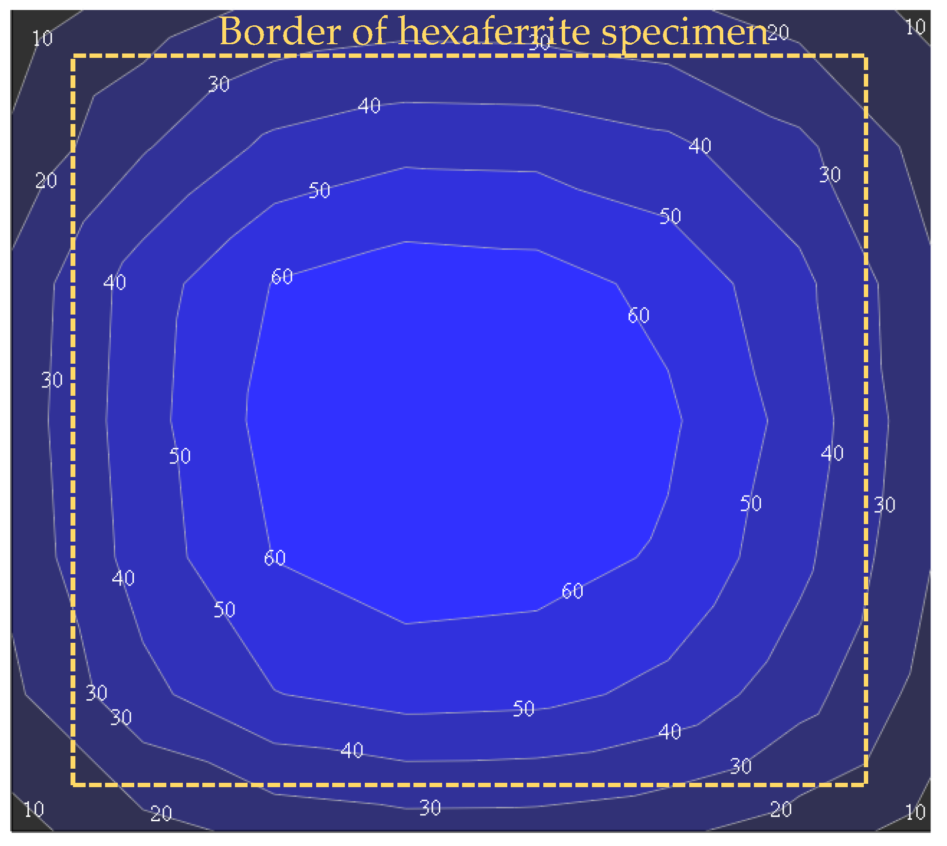
2.2. DC Magnetic Field Profile in Hexaferrite Slab

Distributions of the DC magnetic field HDC on the surfaces of a thin slab of SM-type hexaferrite were mapped by the Hall sensor with an active area of 1.0 × 0.5 mm2. A sample with a surface area of 5.0 × 6.0 mm2 and thickness of 250 ± 3 μm was magnetized to saturation along the c-axis normal to the layer surface.
A contour plot of the normal component of HDC mapped at the height of 3.5 mm above the surface is shown in Figure 2. The measured HDC distributions are similar on both sides of the layer, but the field magnitudes differ slightly due to minor differences in the probe positioning. The measured HDC is fairly uniform above the specimen central area but gradually decreases towards the edges. Such a pattern of HDC suggests that the internal magnetic bias, Hi, in the hexaferrite layer is reasonably homogeneous.
It is necessary to stress that the homogeneity of Hi and remanent magnetization, 4πMr, are the essential prerequisites for the low-loss operation of nonreciprocal ferrite devices. Therefore, La-Co-substituted SM-type hexaferrite slab with inherently strong magneto-crystalline anisotropy, high 4πMr and strong Hc is particularly apt for these applications. Small spatial variations of the demagnetizing field due to the shape of the hexaferrite specimens can be mitigated similarly to [11] where the inhomogeneous DC magnetic bias was applied externally to compensate for the effects of shape and aspect ratio of the hexaferrite specimen.

3. Self-Biased Microstrip Junction Circulators

The junction resonator on the hexaferrite substrate is the core element of the self-biased circulator enabling its nonreciprocal response. Hexaferrite, magnetized along the z-directed c-axis, is described by the Polder tensor of permeability [21]
μ =   μ 0 μ j κ 0 j κ μ 0 0 0 1
where
μ = 1 + ω 0 ω m ω 0 2 ω 2
κ = ω ω m ω 0 2 ω 2
ω 0 = γ H i + j Δ H
ω m = γ 4 π M r
ω is an angular frequency, 4πMr is the remanent magnetization, ω 0 is the complex-valued angular frequency of ferrimagnetic resonance, Hi = Hc is the internal DC magnetic bias equal to the average magnitude of the coercive magnetic field, imposed by the magneto-crystalline anisotropy of hexaferrite, Δ H is the ferrimagnetic resonance linewidth, and γ = 2.8 GHz/kOe is the gyromagnetic ratio.
The geometry of hexaferrite-based Y-junction circulators can be initially approximated with the aid of the models developed in [22,23,24] for the stripline circulators with externally biased ferrite resonators. Bosma’s model [22] defines the approximate relation between circulator operating frequency ω , radius R of the disk-shaped junction resonator, and the hexaferrite relative permittivity ε f and effective permeability μe
k R ε f μ e 1.84
where k = ω/c is the free space wavenumber, c is the speed of light in free space,
μ e = μ 2 κ 2 μ = ω 0 + ω m 2 ω 2 ω 0 ω 0 + ω m ω 2
is an effective permeability and the frequency of the transverse ferrimagnetic resonance
ω = Re ω 0 ω 0 + ω m
Numerical estimates of (2), (3) and (7) show that at the hexaferrite parameters specified in Table 1, μ ≈ 1.23 + 0.002j,   κ ≈ 0.069 + 0.002j, μe ≈ 1.226 + 0.002j are in the middle of the Ku band. It is noteworthy that the magnetic losses of hexaferrite at these frequencies are commensurate to the dielectric losses despite Δ H of the hexaferrite is much larger than that of the soft ferrites. This is the result of the operating frequency offset from the transverse ferrimagnetic resonance (8) at ω/2π ≈ 54.5 GHz, which is dictated by the trade-off between the hexaferrite magnetic loss and gyrotropy at the operating frequencies.
The junction resonator radius R ≈ 0.99 mm was initially obtained from the circulation condition (6) at the hexaferrite parameters specified in Table 1. This approximation of R was about 6% larger than the resonator radius Rd deduced from the full-wave simulations, summarized in Table 2. It should be noted that the accuracy of (6) was also limited by the model assumption that the junction resonator is bounded by the magnetic wall at its circumference. Therefore, the junction resonator radius had to be adjusted to account for the effects of fringing fields and discontinuities of the resonator joints with the output transformers. The correction of R was proposed in [24] but the resulting R values were about 30% smaller than those obtained from the full-wave simulations.
The full-wave EM simulations in CST MW Studio were adopted here for the analysis and modelling of the circulator performance. The correct value of R was particularly important for the design of the self-biased circulator where the internal magnetic bias could not be adjusted without remagnetizing the entire hexaferrite resonator and/or altering its composition. Thus, the microstrip circulators on hexaferrite substrates were analysed and optimised using the parameters specified in Table 1 and the initial value of R obtained from (6).

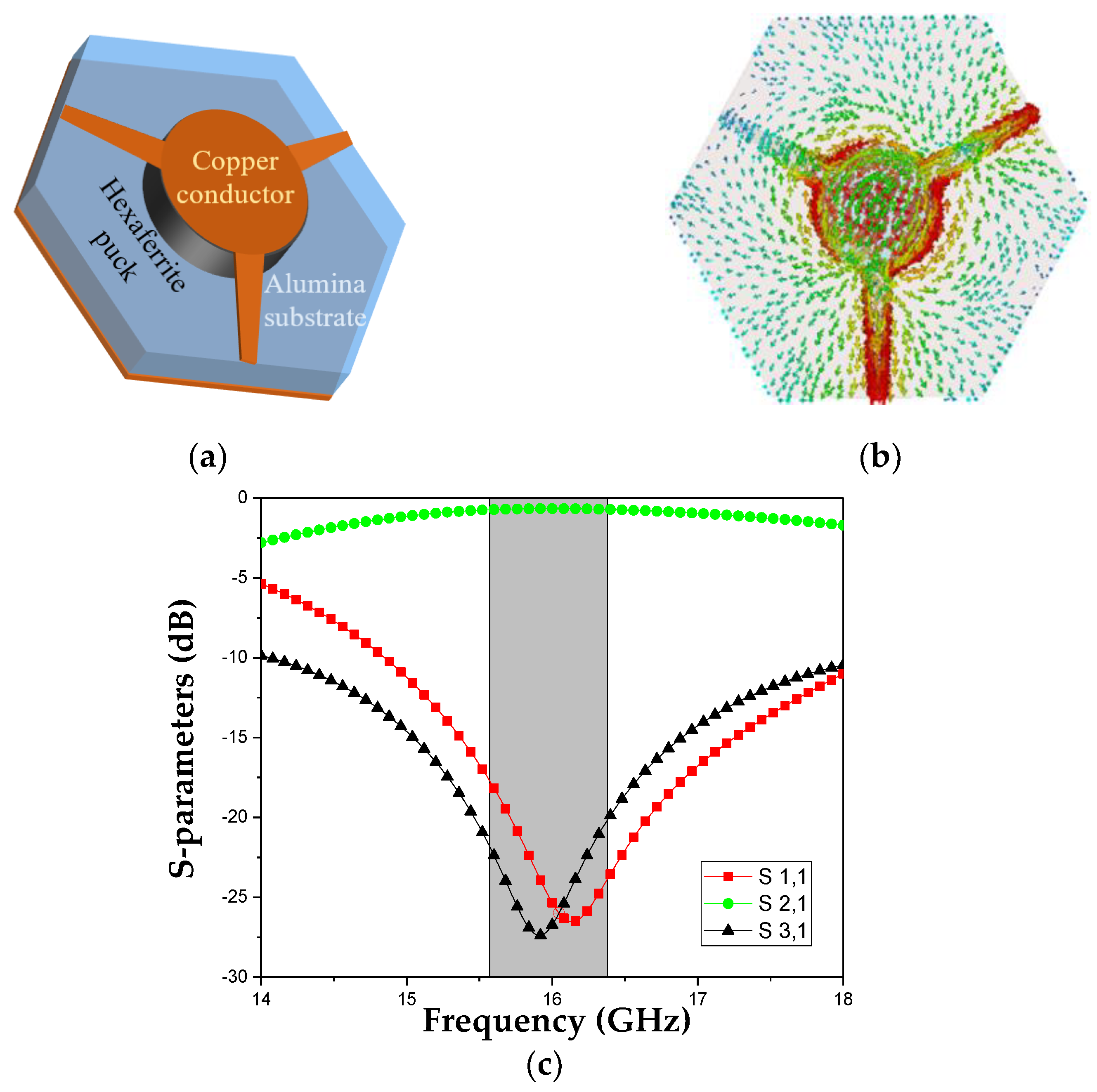
3.1. Analysis of Losses in Self-Biased Microstrip Circulators

High ILs are a major problem in the design of self-biased hexaferrite circulators. Recent progress in the synthesis of hexaferrite materials has enabled magnet-free microstrip and waveguide junction circulators with ILs below 1 dB in the frequency band 30–40 GHz [10,11]. However, at lower frequencies, the ILs in the microstrip circulators on hexaferrite substrates remain stubbornly high, exceeding 1.5 dB in the Ku band [8].
In the conventional microstrip circulator with the cross-section shown in Figure 3a, ILs are incurred by both a junction resonator and matching transformers located on the same hexaferrite substrate. Their individual contributions to the total IL depend on the junction resonator shape, and the substrates of different thicknesses are required for the same operating frequency [1,2]. Namely, the substrate of a disk-shaped junction resonator has to be thicker than that of the apex-fed triangular resonator but thinner than the side-fed triangular resonator. The matching transformers have to be adjusted for each substrate thickness, too. Table 2 summarises the simulated IL, return loss (RL) and isolation (Iso) of the disk and triangular-shaped junction circulators with centre frequency f0 = 16 GHz, and Rd is the radius of the disk-shaped resonator and atri is the side length of the equilateral triangular resonator. The hexaferrite substrates have the same material parameters specified in Table 1 but different thicknesses ts.
Table 2 shows that the RL and Iso of all three types of junction resonators are commensurate. But the IL in the circulator with the disk-shaped resonator is lower than ILs in both circulators with triangular resonators. The circulator with the disk-shaped junction resonator on the hexaferrite substrate also exhibits a slightly lower IL than the circulator on the stacked hexaferrite-Duroid substrate reported in [8]. Further optimization of the circulator layout, including the use of tapered matching transformers, noticeably improves the RL and Iso across a 5.6% frequency band, highlighted grey in Figure 3c. But the IL is barely improved and remains high.
The causes of the stubbornly high IL and the effect of hexaferrite substrate thickness ts on the IL in the disk-shaped junction circulator were examined first. The simulated characteristics of the circulator with several different ts are summarized in Table 3. They show that as the hexaferrite substrate becomes thinner, FBW broadens whilst the RL and Iso remain high. But the reduction of the IL at smaller ts is marginal, and the IL decrement becomes even smaller at thinner substrates.
To identify the causes of the circulator’s high losses, the RF magnetic field distribution was evaluated on the surface of La-Co-substituted SM-type hexaferrite substrate with a disk-shaped junction resonator and matching transformers. The inspection of the magnetic field pattern in the circulator, Figure 3b, reveals two important features:
  • Hot spots exist in the small peripheral regions of the junction resonator near ports 1 and 2 only.
  • Standing wave patterns appear in the matching transformers.
A strong magnetic field at the edges of the junction resonator unavoidably increased the dissipative losses. The contribution of the edge to the overall losses was determined by the localisation of the total power flow at the circumference of the junction resonator, which was proportional to the ratio ts/Rd. Therefore, the IL in the circulators with thinner substrates should be lower, which was confirmed by the simulation results as shown in Table 3.
The field distribution in the matching transformers located on the hexaferrite substrate has the standing wave pattern seen in Figure 3b. Such a pattern causes significant losses that are commensurate or even exceed the losses in the junction resonator itself. To discriminate the individual contributions of the transformers and junction resonator to the total loss, the circulator substrate was modified—the hexaferrite substrate outside the junction resonator disk was replaced by the low-loss alumina substrate of the same thickness as illustrated by Figure 4a. Then the matching transformers were located on the alumina substrate [7]. This modification has several advantages. First, the transformers have no magnetic losses. Second, alumina has a smaller refractive index than hexaferrite puck and increases the field confinement to the junction resonator by reducing the parasitic effect of fringing fields. Thus, the circulator with the composite hexaferrite–alumina substrate has a significantly lower IL as discussed next.

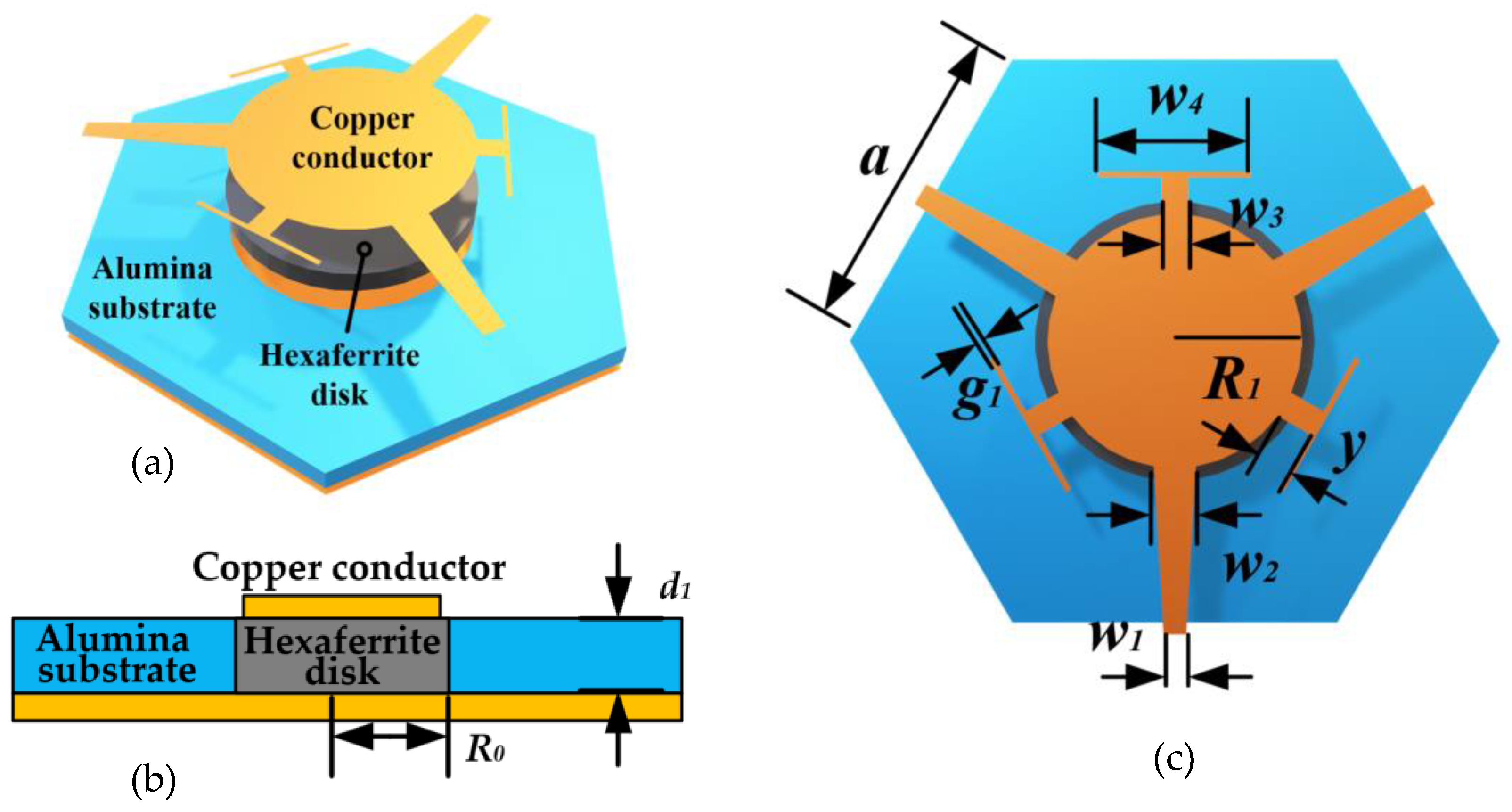
3.2. Self-Biased Microstrip Circulator on Composite Substrate

A circulator with the hexaferrite–alumina substrate of thickness ts = 0.16 mm and the layout shown in Figure 4a was simulated using the hexaferrite parameters specified in Table 1 and the alumina relative permittivity εd = 9.8 and tanδd = 0.0001. Even in the basic circulator layout with the quarter-wave matching transformers, the IL at centre frequency f0 = 16 GHz nearly halved by decreasing from 1.33 dB to 0.79 dB at the RL of 17.5 dB and isolation of 33.2 dB remaining practically unchanged. This is a significant improvement of the IL as compared with the case of the whole circulator on the hexaferrite substrate, illustrated in Table 3. This was the result of the field confinement to the hexaferrite junction resonator and the transformer placement on the low-loss alumina substrate. The FBW of 2.5%, obtained in such a circulator with the composite substrate, remained rather narrow. It was limited by the basic quarter-wave transformers and their suboptimal coupling to the junction resonator. These shortcomings were remedied by the use of the tapered matching transformers that provide a better coupling to the junction resonator.
The circulator layout with tapered impedance transformers on the alumina substrate is shown in Figure 4a. Its IL is further reduced to 0.66 dB at an RL of 25.3 dB and Iso of 26.7 dB at centre frequency f0 = 16 GHz. The RL over 17 dB and Iso over 20 dB were achieved across the FBW over 5% of the highlighted grey area in Figure 4c. Thus, both IL and FBW are noticeably improved here as compared to the circulator with the quarter-wave transformers. A pattern of the RF magnetic field on the substrate surface is shown in Figure 4b. It demonstrates a fairly smooth wave flow through the junction resonator and matching transformers. Further reduction of the IL can be achieved by optimizing the matching transformers and the hexaferrite with a narrower line of ferrimagnetic resonance ΔH.
The effects of fabrication tolerances and variations of the dimensional and material parameters on the circulator characteristics were assessed. The sensitivity analysis showed that deviations of the junction resonator diameter and internal magnetic field Hi from their nominal values have a stronger effect on the circulator performance than the other parameters. But their effect is limited to a shift of the centre frequency that can be readily adjusted by conditioning the magnetic bias or dimensions of the hexaferrite junction resonator.

4. Self-Biased Microstrip Circulators at Low GHz Frequencies

The analysis of the self-biased circulators in Section 3 was based on the averaged parameters of hexaferrite materials. They were deduced from the measurements whereas the actual distribution and magnitude of the DC magnetic bias in the hexaferrite specimens cannot be obtained directly. Namely, the magnitude and orientation of the internal DC magnetic field inside the polycrystalline hexaferrite layer depend not only on the grain size and density but also on their orientation. In the flat specimens, internal magnetic bias was also inhomogeneous as illustrated by the magnetic field pattern in Figure 2. But the effect of the nonuniform magnetic bias was somewhat mitigated with the aid of the more complicated matching circuits and transformers adjusted for the specified operational frequencies as discussed below.

4.1. Requirements to the Hexaferrite Materials for the Low GHz Self-Biased Circulators

For hexaferrite use at the low GHz frequencies, its internal magnetic bias Hi became smaller than the frequency of 4πMr. Therefore, the circulators had to be analysed in the two limiting cases of weak and strong internal demagnetisation separately, viz.
-
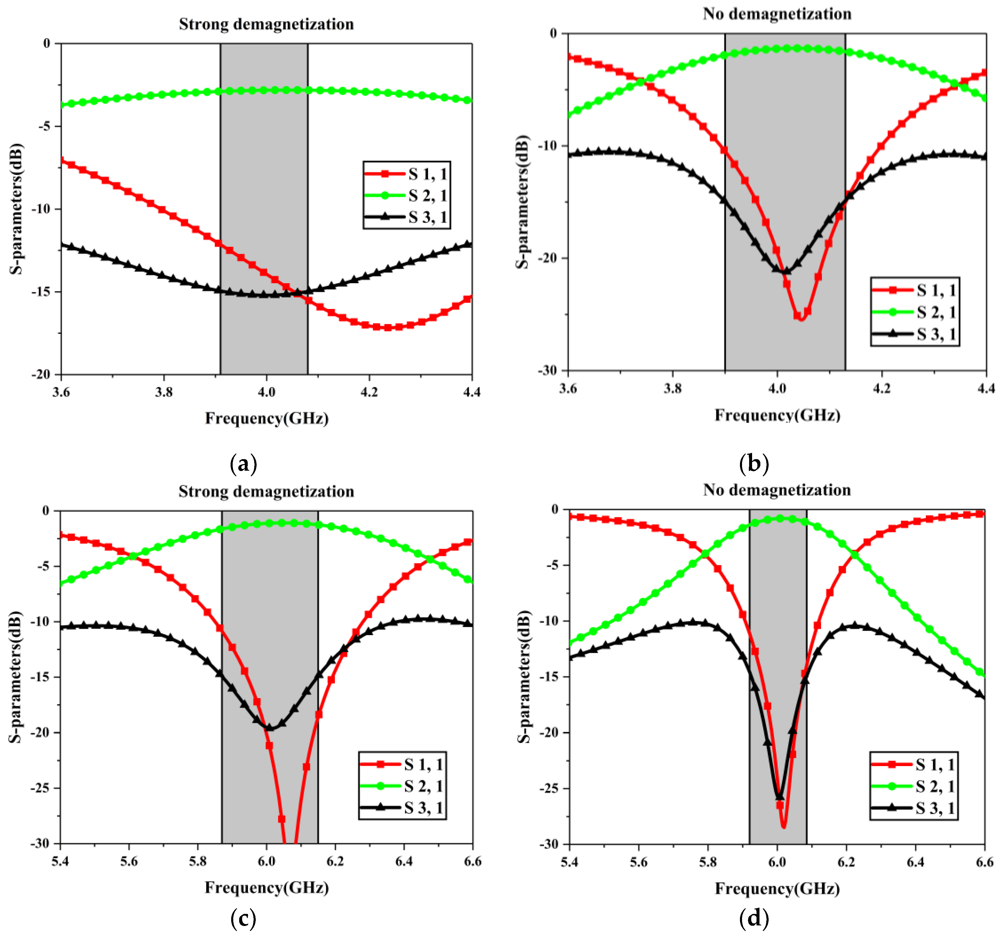
The internal magnetic bias is Hi = Ha − weak demagnetisation (ND).
-
The internal magnetic bias is Hi = Ha – 4πMr − strong demagnetisation (SD).
Hi defines the FMR frequency as
f FMR = γ H i
where γ = 2.8 GHz/kOe is the gyromagnetic ratio and fFMR varies in the wide range
γ ( H a 4 π M r ) f FMR     γ H a
The geometrical parameters of the junction resonator strongly depend on Hi and differ significantly in the two limiting cases.
The operational frequency of the self-biased circulator had to be away from the f FMR frequency to avoid high losses. But it should not be too far from the f FMR to exploit the hexaferrite gyrotropy. Therefore, the internal magnetic bias Hi of the hexaferrite must be carefully tailored to the desired operational frequency. This causes serious difficulties because Ha should be notably larger than 4πMr but small enough for the use at the low GHz frequencies. Therefore, the existing hexaferrite materials developed for the mm-wave frequencies do not meet these requirements.
The losses and the operational band of the circulators are critically dependent on the FMR linewidth ΔH, especially at low GHz frequencies. But synthesis and fabrication of hexaferrites with low Ha and narrow ΔHH ≤ 500 Oe) remain the challenging tasks. The recently developed SM-type hexaferrites have allowed the circulator losses to be reduced below 0.7 dB at the frequencies of 16 GHz as demonstrated in Section 3 but their use at lower frequencies requires further investigations.

4.2. Self-Biased Microstrip Circulators at Low GHz Frequencies

The self-biased microstrip circulators were analysed at frequencies 4 and 6 GHz using the commercially available hexaferrites 08СЧА5В and 08СЧА1В with the parameters are specified in Table 4 [25]. It is necessary to note that the anisotropy field Ha of these hexaferrites is too strong for the considered operational frequencies that results in a weak gyrotropy. Therefore, the designed circulators have narrow bandwidths and high losses at the specified frequencies.
Similar to the circulator discussed in Section 3, a composite substrate was made of a hexaferrite disk embedded in the surrounding alumina layer of the same thickness. The circulator layout with the impedance transformers and advanced matching circuits is shown in Figure 5. The matching circuits were modified for the lower frequency use and to alleviate the limitations imposed by the parameters of the existing hexaferrite materials. Three outstretched lengths of the transmission lines with extension stripes at the ends were added for the impedance matching of the junction. The dimensions of the junction resonators and the matching circuits are summarised in Table 5 for the ND and SD cases.
The S-parameters of the self-biased circulator with the hexaferrite 08СЧА5В were simulated at the centre frequency 4 GHz. Figure 6a,b show the two extreme cases of SD and ND of the hexaferrite disk with internal magnetic bias Ha = 6 kOe and FMR linewidth ∆H = 2.5 kOe. In the SD case, shown in Figure 6a, the isolation exceeds −15dB when frequency varies from 3.92 to 4.08 GHz, i.e., a fractional bandwidth (FBW) is 4%. The RL is above 12.4 dB and the IL varies from 2.8 dB at a centre frequency to 2.9 dB at the band edges. In the ND case shown in Figure 6b, the FMR frequency is further away from the operational band, and the internal magnetic bias is lower. This results in the lower IL ranging from 1.3 dB to 1.9 dB and the RL above 10.7 dB across the specified operational band. But the Isolation band at the level of -20 dB is narrower here, varying from 3.98 GHz to 4.05 GHz.
The characteristics of the self-biased circulator in the 6 GHz band are illustrated in Figure 6c,d. A hexaferrite 08СЧА1В was used here. It has a larger Ha = 11 kOe and the same ∆H = 2.5 kOe. The simulation results in the SD case show that the IL is notably lower, varying from 1.1 dB at the centre frequency to 1.6 dB at the band edges, whilst RL is above 11.2 dB at the band edges. The frequency band of Isolation at the level of −15 dB ranges from 5.87 to 6.15 GHz and the FBW is 4.7%. In the case ND, the IL is lower and varies from 0.8 dB at the centre frequency to 1.3 dB at the band edges, whilst the RL is above 11.6 dB at the band edges. The frequency band of Isolation at the level of -15 dB varies from 5.92 to 6.08 GHz that corresponds to the narrower FBW of 3.7%.
The circulator BW, IL, RL and isolation are the interdependent characteristics. Therefore, their optimal values cannot be realised simultaneously. As a result, some trade-offs can be made in the design of the circulator transformers. The effect of the matching circuit dimensions w2 and w4 on the circulator S-parameters is illustrated in Figure 7 for the case of strong demagnetisation. It shows that a higher transmission and wider bandwidth can be obtained at the cost of reducing isolation. By changing w2 from 0.7 mm to 1.1 mm, the transmission FBW at the level of −3 dB widens from 9.05% to 12.53%, but the IL increases for 0.34 dB and the isolation band becomes narrower and shallower at a larger w2. A trade-off between the IL and isolation exists when increasing the w4, which is the length of the matching strips at the end of the outstretched arms shown in Figure 5c. It is seen in Figure 7c that the IL increases from 1.3 dB to 1.36 dB when w4 increases from 3 mm to 5 mm. But the opposite trend of deepening and widening the isolation curves is observed in Figure 7d. Thus, better matching circuits are necessary for the design of the self-biased circulators in the low GHz frequency bands.

5. Conclusions

The mechanisms of RF loss in self-biased microstrip circulators on hexaferrite substrates have been examined, and a means of significant loss reduction in the three frequency bands are discussed. The La-Co-substituted hexaferrites with strong magneto-crystalline anisotropy are used for the design of the self-biased circulators in the Ku, X and C bands.
The pattern of the DC magnetic field is mapped first above the hexaferrite layer surface. It suggests that the magnetic bias is fairly uniform inside a thin hexaferrite layer. The hexaferrite parameters retrieved from the measurement data are used for the full-wave analysis of the self-biased microstrip circulators. It is found that the insertion losses are slightly lower in the circulators with thinner hexaferrite substrates, and this is attributed to a weaker effect of the fringing field at the edges of the junction resonators.
The causes of the high losses in self-biased circulators were examined and individual contributions of the matching transformers and junction resonators were separated. Our analysis has revealed that the matching transformers, located on the hexaferrite substrate, make a major contribution to the circulator’s overall losses. To reduce the circulator losses, it is suggested that a composite hexaferrite–alumina substrate be used, where the hexaferrite disk is confined to a junction resonator only whilst the matching transformers are placed on the surrounding alumina substrate. Then the ILs are reduced by more than half. Merits of such an arrangement are illustrated by an example of the Ku band circulator on the hexaferrite–alumina substrate where the IL can be reduced to 0.66 dB at the RL over 17 dB and isolation over 20 dB across the FBW over 5%. These significant improvements of the IL and FBW of the self-biased circulators have made them viable candidates for integration in the RF front-end modules and active antennas.
The self-biased circulators for the low-GHz communications bands have been examined in the C and X bands. In the C band, the 4 GHz self-biased circulators with 08СЧА5В hexaferrite are analysed separately in the extreme cases of the strong and weak demagnetisations. It is found that when the hexaferrite substrate is strongly demagnetised, circulator ILs are high and vary from 2.8 to 2.9 dB at isolation about -15 dB in the FBW of 4%. In the case of weak demagnetization, the IL is lower, varying from 1.3 to 1.9 dB. In the X band, the self-biased circulators are simulated with 08СЧА1В hexaferrite. In the case of strong demagnetisation, the ILs of the circulator are notably lower, varying from 1.1 dB to 1.6 dB across the FBW of 4.7%. In the case of weak demagnetization the operational frequency is farther away from the FMR. This results in the lower ILs varying from 0.8 to 1.3 dB, but the obtained operational bandwidth remains narrow.
The presented analysis demonstrates the great potential of the self-biased circulators for the current and future communications systems operating in the low and mid GHz frequency bands.

Author Contributions

Conceptualization, Y.H. and A.S.; investigation, S.J., L.K. and T.E.; methodology, validation, writing—original draft and visualization, L.K. and S.J.; writing—review and editing, Y.H. and A.S. All authors have read and agreed to the published version of the manuscript.

Funding

This research was funded by Huawei Technologies Sweden AB.

Data Availability Statement

Restrictions apply to the availability of these data. Data is available with the permission of the author.

Acknowledgments

We would like to acknowledge the help and comments from other colleagues at the University of Liverpool and Huawei Technologies Sweden.

Conflicts of Interest

The authors declare no conflict of interest.

References

  1. Helszajn, J. The Stripline Circulator; John Wiley & Sons: Hoboken, NJ, USA, 2008; ISBN 9780470264140. [Google Scholar]
  2. Linkhart, D.K. Microwave Circulator Design; Artech House: Boston, MA, USA, 2014; ISBN 9781608075836. [Google Scholar]
  3. Adams, R.S.; O’Neil, B.; Young, J.L. The Circulator and Antenna as a Single Integrated System. IEEE Antennas Wirel. Propag. Lett. 2009, 8, 165–168. [Google Scholar] [CrossRef]
  4. Chen, Y.; Geiler, A.L.; Sakai, T.; Yoon, S.D.; Vittoria, C.; Harris, V.G. Microwave and Magnetic Properties of Self-Biased Barium Hexaferrite Screen Printed Thick Films. J. Appl. Phys. 2006, 99, 08M904. [Google Scholar] [CrossRef]
  5. Geiler, A.L.; Harris, V.G. Atom Magnetism: Ferrite Circulators—Past, Present, and Future. IEEE Microw. Mag. 2014, 15, 66–72. [Google Scholar] [CrossRef]
  6. Harris, V.G. Modern Microwave Ferrites. IEEE Trans. Magn. 2012, 48, 1075–1104. [Google Scholar] [CrossRef]
  7. O’Neil, B.K.; Young, J.L. Experimental Investigation of a Self-Biased Microstrip Circulator. IEEE Trans. Microw. Theory Tech. 2009, 57, 1669–1674. [Google Scholar] [CrossRef]
  8. Wang, J.; Yang, A.; Chen, Y.; Chen, Z.; Geiler, A.; Gillette, S.M.; Harris, V.G.; Vittoria, C. Self-Biased Y-Junction Circulator at Ku Band. IEEE Microw. Wirel. Compon. Lett. 2011, 21, 292–294. [Google Scholar] [CrossRef]
  9. Peng, B.; Xu, H.; Li, H.; Zhang, W.; Wang, Y.; Zhang, W. Self-Biased Microstrip Junction Circulator Based on Barium Ferrite Thin Films for Monolithic Microwave Integrated Circuits. IEEE Trans. Magn. 2011, 47, 1674–1677. [Google Scholar] [CrossRef]
  10. Fitchorov, T.; Geiler, A. Miniaturized, Low-Cost, Self-Biased Circulators for Space and Airborne Applications; Earth Science Technology Forum: Annapolis, MD, USA, 14–16 June 2016. [Google Scholar]
  11. Laur, V.; Vérissimo, G.; Quéffélec, P.; Farhat, L.A.; Alaaeddine, H.; Laroche, E.; Martin, G.; Lebourgeois, R.; Ganne, J.P. Self-Biased Y-Junction Circulators Using Lanthanum- and Cobalt-Substituted Strontium Hexaferrites. IEEE Trans. Microw. Theory Tech. 2015, 63, 4376–4381. [Google Scholar] [CrossRef]
  12. Self Biased Circulators and Isolators, Metamagnetics Inc. Available online: https://www.mtmgx.com/rf-microwave-smt-circulators-isolators/ (accessed on 13 November 2022).
  13. Kodera, T.; Sounas, D.L.; Caloz, C. Artificial Faraday Rotation Using a Ring Metamaterial Structure without Static Magnetic Field. Appl. Phys. Lett. 2011, 99, 031114. [Google Scholar] [CrossRef]
  14. Kodera, T.; Sounas, D.L.; Caloz, C. Magnetless Nonreciprocal Metamaterial (MNM) Technology: Application to Microwave Components. IEEE Trans. Microw. Theory Tech. 2013, 61, 1030–1042. [Google Scholar] [CrossRef]
  15. Reiskarimian, N.; Krishnaswamy, H. Magnetic-Free Non-Reciprocity Based on Staggered Commutation. Nat. Commun. 2016, 7, 11217. [Google Scholar] [CrossRef] [PubMed]
  16. Sounas, D.L.; Soric, J.; Alù, A. Broadband Passive Isolators Based on Coupled Nonlinear Resonances. Nat. Electron. 2018, 1, 113–119. [Google Scholar] [CrossRef]
  17. Hessien, M.M.; Radwan, M.; Rashad, M.M. Enhancement of Magnetic Properties for the Barium Hexaferrite Prepared through Ceramic Route. J. Anal. Appl. Pyrolysis 2007, 78, 282–287. [Google Scholar] [CrossRef]
  18. Drung, D.; Abmann, C.; Beyer, J.; Kirste, A.; Peters, M.; Ruede, F.; Schurig, T. Highly Sensitive and Easy-To-Use SQUID Sensors. IEEE Trans. Appl. Supercond. 2007, 17, 699–704. [Google Scholar] [CrossRef]
  19. Labeyrie, M.; Mage, J.; Robinson, T. Characterisation of Strontium Hexaferrite for Millimeter Waves Applications. IEEE Trans. Magn. 1986, 22, 976–980. [Google Scholar] [CrossRef]
  20. Baker-Jarvis, J.; Vanzura, E.J.; Kissick, W.A. Improved Technique for Determining Complex Permittivity with the Transmission/Reflection Method. IEEE Trans. Microw. Theory Tech. 1990, 38, 1096–1103. [Google Scholar] [CrossRef]
  21. Lax, B.; Button, K.J. Microwave Ferrites and Ferrimagnetics; McGrow-Hill: New York, NY, USA, 1962. [Google Scholar]
  22. Bosma, H. On Stripline Y-Circulation at UHF. IEEE Trans. Microw. Theory Tech. 1964, 12, 61–72. [Google Scholar] [CrossRef]
  23. Fay, C.E.; Comstock, R.L. Operation of the Ferrite Junction Circulator. IEEE Trans. Microw. Theory Tech. 1965, 13, 15–27. [Google Scholar] [CrossRef]
  24. Wu, Y.S.; Rosenbaum, F.J. Wide-Band Operation of Microstrip Circulators. IEEE Trans. Microw. Theory Tech. 1974, 22, 849–856. [Google Scholar] [CrossRef]
  25. Hexaferrite Materials. Available online: https://www.domen.ru/files/upload/2020-12-24_15:46:22_25d13f31ce5136b6.pdf (accessed on 12 November 2022). (In Russian).
Figure 1. Hysteresis curves of magnetization 4πM(Hex) normalized to the saturation magnetization 4πMs ≈ 4500 Gs for the M-type (red line) and SM-type (blue line) hexaferrites. DC magnetic field Hex is directed along the easy c-axis.
Magnetism 03 00010 g001
Figure 2. Pattern of the normal component of DC magnetic field HDC measured in Oe at the height of 3.5 mm above the hexaferrite slab with a surface area of 5.0 × 6.0 mm2 and thickness of 250 μm.
Magnetism 03 00010 g002
Figure 3. Self-biased disk-shaped junction circulator on hexaferrite substrate of thickness ts = 0.17 mm biased by the internal magnetic field Hi normal to the surface. (a) microstrip circulator cross-section; (b) pattern of the RF magnetic field on the substrate top surface at frequency f0 = 16 GHz; (c) the simulated S-parameters.
Magnetism 03 00010 g003
Figure 4. Self-biased disk-shaped junction circulator on a composite hexaferrite–alumina substrate with the internal magnetic bias field Hi normal to the surface. (a) microstrip circulator layout; (b) RF magnetic field distribution on the substrate top surface at frequency f0 = 16 GHz; (c) simulated S-parameters. The junction resonator radius is 0.91 mm; the transformer length is 1.8 mm and the width of the tapered transformers varies from 0.36 mm at the proximity end to 0.14 mm at the distal end; substrate thickness ts = 160 μm and hexagon side length is 5.68 mm.
Magnetism 03 00010 g004
Figure 5. Self-biased microstrip junction circulator with matching circuits: (a) exploded view of the circulator layout. (b) Cross-section of the structure. (c) Top view with the geometrical parameter definitions.
Magnetism 03 00010 g005
Figure 6. The simulation results of the self-biased microstrip circulators for 4 GHz (a,b) and 6 GHz (c,d) in the cases of strong demagnetisation (SD)—(a,c) and no demagnetisation (ND)—(b,d).
Magnetism 03 00010 g006
Figure 7. The simulated characteristics of the 4 GHz self-biased microstrip circulator with strong demagnetisation in the cases of variable w2: (a,b) and w4: (c,d).
Magnetism 03 00010 g007
Table 1. Parameters of La-Co-substituted SM-type hexaferrite substrate.
Ms, kGsMr , kGsHc, kOeεftan δfΔH, OeΔHeff, Oe
4.54.019.1250.002100020
Table 2. Dimensions and characteristics of the circulators on hexaferrite substrates.
Junction
Resonators
ts, mmRd, mmatri, mmRL *, dBIso *, dBIL *, dB
Magnetism 03 00010 i0010.170.93-37.928.41.33
Magnetism 03 00010 i0020.09-2.4633.721.51.66
Magnetism 03 00010 i0030.34-2.0231.525.71.71
* IL, RL and Iso are at frequency f0 = 16 GHz.
Table 3. Characteristics of the disk-shaped junction circulator on hexaferrite substrates of different thicknesses ts at centre frequency f0 = 16 GHz.
ts, mmIL, dBRL, dBIso, dBFBW, %
0.2531.5824.2724.03.5
0.171.3339.728.45.6
0.141.3127.835.46.7
0.121.2926.038.66.9
Table 4. Parameters of the hexaferrite materials [25] used for the circulator simulations.
MaterialMs, kOeMr, kOeHa, kOeεftan δfΔH, Oe
08СЧА5В3.43.066170.0012500
08СЧА1В3.73.3311170.0012500
Table 5. Dimensions in mm of the self-biased circulators for 4 GHz and 6 GHz frequency bands.
f0, GHzCaseaw1w2w3w4g1d1yR0 *
4SD12.00.351.171.14.00.20.41.652.9
ND12.00.080.621.34.00.20.11.753.6
6SD6.00.170.950.63.00.20.20.752.5
ND6.00.080.930.62.80.20.11.302.6
* The hexaferrite disk radius R0 is 5% larger than the junction conductor radius R1.
Disclaimer/Publisher’s Note: The statements, opinions and data contained in all publications are solely those of the individual author(s) and contributor(s) and not of MDPI and/or the editor(s). MDPI and/or the editor(s) disclaim responsibility for any injury to people or property resulting from any ideas, methods, instructions or products referred to in the content.

