Extension of the Application Range of Multipolar Bonded Ring Magnets by Thermosets in Comparison to Thermoplastics


Institute of Polymer Technology, Friedrich-Alexander-Universität Erlangen-Nürnberg, 91058 Erlangen, Germany
*
Author to whom correspondence should be addressed.
Magnetism 2023, 3(1), 71-89; https://doi.org/10.3390/magnetism3010007
Submission received: 21 February 2023
/
Revised: 9 March 2023
/
Accepted: 17 March 2023
/
Published: 20 March 2023
Abstract
:To expand the range of applications of multipolar bonded magnets based on a thermoplastic matrix, the chemical and thermal resistance has to be increased and the reduced orientation in the rapid solidified surface layer has to be overcome. To meet these requirements, the matrix of multipolar bonded magnets can be based on thermosets. This paper investigates in the magnetic properties, especially in the orientation of hard magnetic fillers, the pole accuracy and the mechanical properties of multipolar bonded ring magnets based on the hard magnetic filler strontium-ferrite-oxide and compares the possibilities of thermoplastic (polyamide)- and thermoset (epoxy resin, phenolic resin)-based matrices. It was shown that the magnetic potential of the thermoset-based material can only be fully used with further magnetization. However, the magnetic properties can be increased using thermoset-based compounds compared to thermoplastics in multipolar bonded ring magnets. Further, a model of the orientation and pole accuracy is found in terms of thermoset-based multipolar magnets. In addition, the change of the mechanical properties due to the different matrix systems was shown, with an increase in E-Modulus, Et, and a reduction in tensile strength, σm, and elongation at break, εm, in terms of thermosets compared to thermoplastics.
1. Introduction
Polymer-bonded magnets are based on a matrix material (thermoplastic, thermoset, elastomer) and a hard magnetic filler (e.g., strontium-ferrite-oxide (SrFeO) or neodymium-iron-boron (NdFeB)). In some cases, additives are added to serve specific demands within the application [1]. Until know, the matrix material defines the possible fabrication process of polymer-bonded magnets. Thermoplastic-based systems are therefore fabricated mainly within the injection moulding process, reaching a limitation of the filler content at 60 vol.-% [2] due to the increase in the viscosity [3]. Thermoset-based systems are fabricated in pressing processes [4], with a limitation of the filler grade at approximately 85 vol.-% [2]. Due to the increase in the filler grade, higher magnetic properties can be reached. The benefits of the injection moulding process is in general the freedom of the design of the parts [5], the size accuracy [2], which can even be reached for small and thin-shaped samples [6] and a functional integration, for example by inserting metallic components [7].
The two main fields of polymer-bonded magnets within the application are the sensors and the drive technology, whereby the magnetic excitation of synchronous or direct current (DC) machines are mainly realized in terms of applications in the drive technology [8]. As samples within the drive technology reveal a complex geometry and a more magnetic structure, they have to be fabricated by injection moulding, which limits the possible matrix material. For example, [9] reveals the possibility of integration by fabricating the rotor of a pump motor with integrated paddle by injection moulding with six poles of a permanent magnet placed on the outer diameter of the shaft [9]. Further, [10] realized an injection-moulded rotor with three different magnetic tracks for the commutation, the recording of the speed and the working track for the electro motor [10]. As thermoplastics show a general lack of temperature and media resistance [11], as well as a lack of orientation, mainly on the surface layer due to fast cooling coats [12], the possibility of application fields is limited. Thermoset-based polymer-bonded magnets fabricated by injection moulding reveal the opportunity to expand the applications within the drive technology, not only due to a higher temperature and media resistance, but also due to a lower viscosity and a higher ability of fillers to be orientated, which goes along with an improvement of the magnetic properties, as well as less shrinkage and creep [11]. With that, polymer-bonded magnets based on thermosets could meet the demands, for example, in the drive technology of cooling water pumps or the chemical industry. However, as yet, thermosets are mainly fabricated by the pressing process in terms of polymer-bonded magnets. To expand the possible applications of polymer-bonded magnets, the opportunity of fabricating thermoset-based systems in the injection moulding process has to be presented.
1.1. Magnetic Properties
In order to realize magnetic properties in polymer-bonded magnets, hard magnetic fillers have to be implemented into the material system. The fillers differ in terms of the magnetic properties, geometry and particle size. The two main groups are hard ferrites, such as SrFeO, with a hexagonal geometry and a particle size of 1–10 µm and rare earths, such as NdFeB, with a plate-like structure and a particle size of 100–400 µm. NdFeB reveals a two to three times higher resistance against demagnetization compared to SrFeO [13]. Further, the fillers have to be divided into isotropic and anisotropic magnetic properties, where the remanence Br of anisotropic fillers reaches approximately 85% of the saturation flux density, Bs, and isotropic fillers only 50% [5]. In the case of anisotropic fillers, the magnetic moments have to be orientated. The magnetization can be realized within the production or afterwards by using, for example, impulse magnetization [3]. The orientation within the injection moulding process highly affects the magnetic properties of the sample. With that, a certain outer magnetic field strength has to be reached to realize a proper orientation [2]. The orientation and part-magnetization of the hard magnetic fillers is realized using a permanent magnet or an electromagnetic coil and a current through this conductor within the process [3]. Further increase in the magnetic properties beside the orientation of the hard magnetic fillers can be reached by increasing the filler content or mixing different particle types and/or sizes. However, the general increase in the filler content can result in a particle interaction, which becomes more likely with higher filler grades [14].
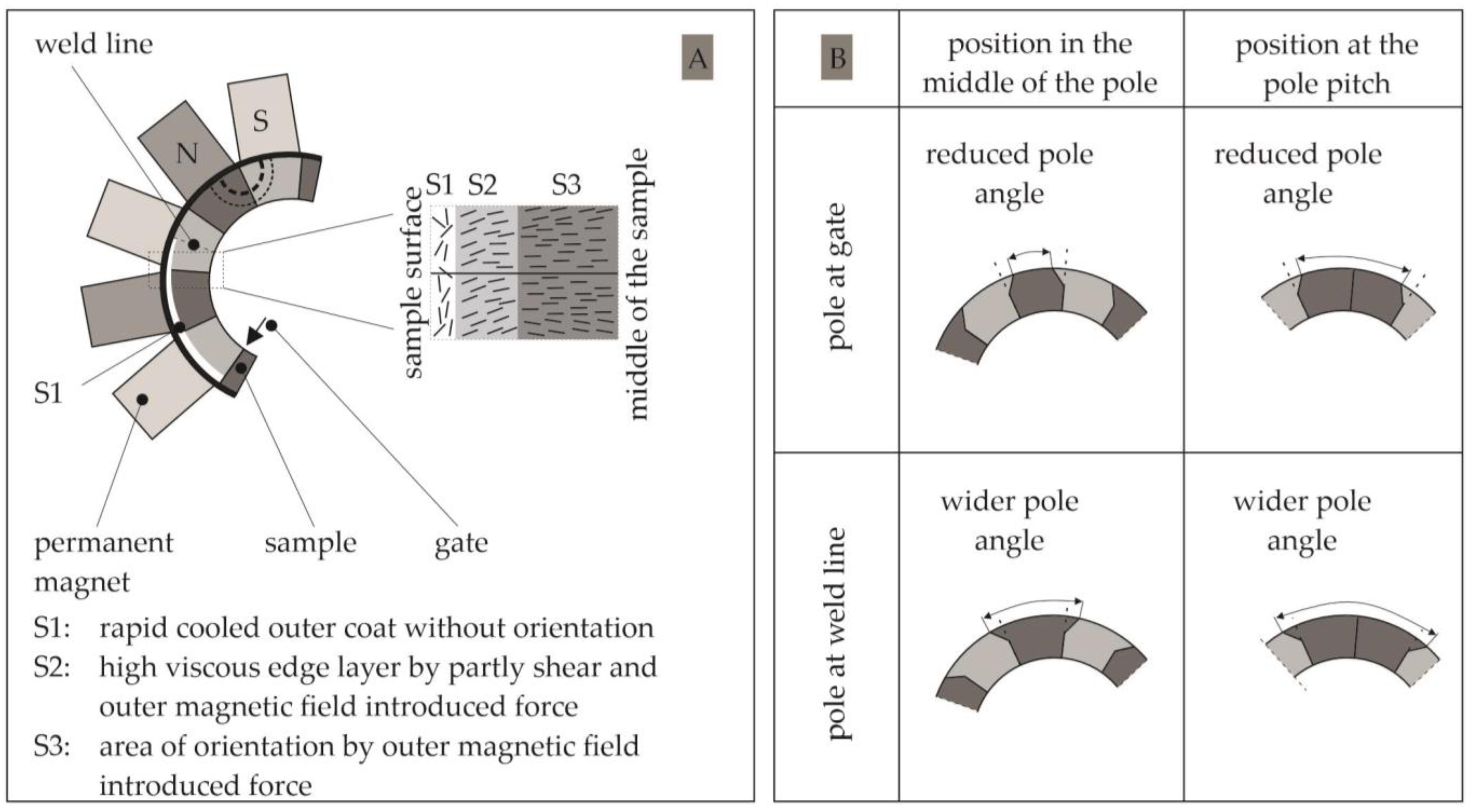
With respect to the polymer-bonded magnets fabricated by the injection moulding process, much research has been carried out in terms of a thermoplastic-based system. The general understanding of polymer-bonded magnets based on thermoplastics can be found in [2], based on a bipolar plate. The main influencing factors on the magnetic properties, such as the holding pressure, ph, and the mass temperature, Tm, have been defined [2]. However, the increase in the mass temperature, Tm, is limited due to filler oxidation processes and the degeneration of the matrix material. Further, a context between the density of the sample and the possible magnetic properties that can be reached was found [15]. Mainly within material systems based on anisotropic fillers, the orientation of the particles has a high impact on the magnetic properties of the sample. Therefore, the filler size distribution plays an important role within the increase in the magnetic properties, as shown in [16], with respect to NdFeB fillers. Ref. [17] applied this basic knowledge to multipolar plates and found a model of orientation in the plate structures. Ref. [12] expanded the understanding to multipolar ring structures and investigated the concept in a second model of orientation with respect to the sample geometry. As shown in Figure 1A, the orientation is only realized due to the outer magnetic field strength in the inner part of the sample. On the outer diameter, a fast cooling of the outer layer takes place, which hinders any kind of orientation. After this phase of rapid cooling, the orientation is influenced by both shear and outer magnetic field introduced forces. This leads to an increase in the orientation grade towards the inner diameter, whereas the highest orientation in terms of many applications should be reached on the outer diameter. Further, the shift of the pole accuracy in terms of the position of the gate (in the pole pitch or the middle of the pole) was investigation and portrayed by a model, as shown in Figure 1B [12].
Thermoset-based polymer-bonded magnets fabricated in an injection moulding process have only been investigated in a few papers. This investigation is realized with a great lack of a system, leading to different statements and a missing basic knowledge of the behaviour of thermoset-based polymer-bonded magnets within the injection moulding process. For example, [18] defined an increase in the magnetic properties by spherical, small particles without investigation of spherical, large or plate-like small particles. A general feasibility of fabricating polymer-bonded magnets based on thermosets within the injection moulding process was proven in [19] with unsaturated polyester resin (UP) and SmFeN with 60 vol.-% filler grade. The magnetic properties could be improved by up to 25% compared with thermoplastic-based material systems on thin plates as sample geometry. However, the thickness of the plate was limited to 0.5 mm due to a temperature-driven increase in the viscosity during curing [19]. The exact chemical mechanism of the impact of the viscosity onto the magnetic properties has yet to be discussed. Ref. [18] revealed that the impact of the outer magnetic field onto the orientation of the hard magnetic fillers is low in terms of thermoset-based material systems, as 50% of the orientation is reached based on flow conditions. This orientation can only be increased by up to 70% in terms of thermoset-based bonded magnets. In terms of thermoplastic-based systems, 60% of the orientation is reached by flow conditions, which is increased up to 95% due to the outer magnetic field [18]. Ref. [20] proved that a pure iron phase within the filler NdFeMo-N supports the growth of magnetic domains in EP-based systems by nucleation [20]. The first methodical attempts to generate a basic and fundamental understanding of thermoset-based polymer bonded magnets, fabricated in the injection moulding process, were made in [21,22], where a material model in terms of the cross-link structures between the filler and the matrix material was found. Further, the influence of this model, or more precisely the influence of the material properties on the magnetic and mechanical properties, was characterized.
1.2. Injection Moulding
The setting of the injection moulding process differs significantly between thermoplastic- and thermoset-based material systems. The plastification of thermoplastics starts at a high temperature in the screw. After injection into the cavity, which reveals a low temperature, the melt is rapidly cooled down with a fast increase in the viscosity [23]. Due to the temperature profile, the viscosity reaches a high value within the cavity, which hinders the orientation of the hard magnetic fillers [24]. In general, thermoplastics reveal a temperature field where they can be melted and solidified several times, as long as the degradation temperature is not reached. Thermoplastics reveal linear carbon chains with a weak physical bond [11].
Thermosets undergo a change in the chemical structure under high temperature, leading to a cross-linking process of the polymer chains. After the curing process, a three-dimensional network based on chemical primary valency bonding is developed. This hinders a second melting of the thermosets and shows one of the main differences between thermoplastics and thermosets [11]. With that, plastification of thermosets in the injection moulding process has to occur at low temperatures so that the temperature-driven curing processes are hindered so that they do not start before the material reaches the cavity. The cavity reveals a high temperature, which first reduces the viscosity and leads to the lowest value of the viscosity in the cavity and secondly triggers the curing process [25]. It is assumed that the orientation of hard magnetic fillers in thermosets is more likely to occur, even in the edge zone of the tool surface, as the minimal viscosity of the material is reached within the cavity.
1.3. Aim of the Paper
This paper aims to investigate the difference between the mechanical and magnetic properties of thermoplastic- and thermoset-based polymer-bonded magnets with the hard magnetic filler SrFeO and a constant filler grade of 55 vol.-%. In detail, a brief material characterization regarding the reaction kinetics and the viscosity behaviour of a polyamide 12 (PA12) as a thermoplastic type and an epoxy resin (EP) as well as a phenolic resin (PF) as two thermoset types is realized. Based on the general differences in the material behaviour of thermoplastics and thermosets, the mechanical and magnetic properties are portrayed and correlated with the material characterization. This fundamental comparison of the two matrix types in terms of polymer-bonded magnets fabricated in the injection moulding process shall reveal the opportunities given by thermoset-based magnets to expand the possible applications.
2. Materials and Methods
2.1. Materials
The matrix material within these experiments was a polyamide 12 (PA12) of type Vestamid BS 1636 (Evonik Industries AG, Essen, Germany), in terms of the thermoplastic matrix, and an epoxy resin (EP) of type Epoxidur EP 368/1 (Raschig GmbH, Ludwigshafen, Germany), as well as a phenolic resin (PF) of type Resinsol EPF 87120 (Raschig GmbH, Ludwigshafen, Germany), in terms of the thermoset matrix. The two thermosets are premixed black powder with resin, hardener, catalyst and, in terms of EP, some carbon black pigments. The exact composition of the mixture is confidential and a business secret of Raschig GmbH. Table 1 reveals the important properties of the matrix materials, where the density, φ, the heat capacity, c, and the peak temperature, Tpeak, are based on our own measurements. The thermal conductivity, λ, is based on the manufacturer specifications. The peak temperature, Tpeak, is defined using a differential scanning calorimetry (DSC) according to DIN EN ISO 11357, with a constant rate of 10 K per minute in terms of PA12 and EP and 5 K per minute in terms of PF. For PA12, Tpeak is defined in the second heating period, and for the two resins, it is defined in the first heating period. Due to the different behaviours of the matrix materials, the setting of the material analysis has to be differentiated to some extent. This is based on the different chemical behaviour of thermoplastics and thermosets.
The experiments were conducted with the hard magnetic fillers of anisotropic strontium-ferrite-oxide (SrFeO) of type OP-71 (Dowa Holdings Co., Ltd., Tokyo, Japan) and a constant filler grade of 55 vol.-%. Table 2 shows the main properties of the filler, which are based on our own measurements.
2.2. Fabrication of the Test Specimens
The production of the test specimens was divided into two parts—the production of the compounds and the fabrication of the test specimens by injection moulding. In the case of PA12-based compounds, a twin-screw extruder (type: ZSE HP-40D, Leistritz AG, Fürth, Germany) was used, where the filler and the polymer granulate was added gravimetrically at different positions along the screw using a doser (K-Tron Deutschland GmbH, Genhausen, Germany). The temperature was set between 180 °C at the entry and 220 °C at the nozzle, with a speed of 90 min−1. The cooling was realized by a vibratory feeder, followed by pelletizing.
In the case of the resin-based compounds, a manual mixing of the two components (matrix material, filler) was realized in the dry state at room temperature. The proportion of the filler and the matrix material was defined using a high-precision weighted device. To realize a homogeneous and sufficient mixing, an optical control took place. This mixed compound was fabricated by a twin-screw extruder (type: Kraus Maffei Berstorff ZSE 25Ax45D, KrausMaffei Group, Munich, Germany) with a speed of 80 min−1. The temperature was set between 50 °C at the entry and 90 °C at the nozzle, to ensure that the material did not cure within the extruder. The cooling was again realized by a vibratory feeder, followed by pelletizing.
The fabrication of the test samples had to be further divided into the ring samples and the plates, which were needed for measurement of the mechanical properties. In the case of PA12, both sample types were produced using an injection moulding machine (type: Demag Ergotech 25/280-80, Sumitomo (SHI) Demag Plastics Machinery GmbH, Schwaig, Germany), with a screw diameter of 18 mm. The processing conditions for both sample types were kept constant, as shown in Table 3.
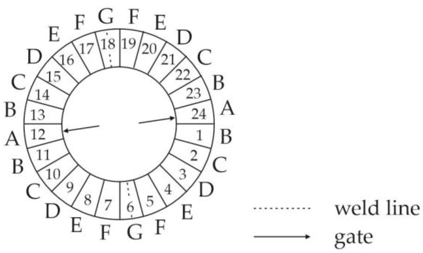
The dimensions of the multipolar bonded ring sample revealed an outer diameter of 30.6 mm, an inner diameter of 22.6 mm and a width of 5 mm. The gating system was a two pinpoint system located at the inner diameter and in the middle of the pole. The sample revealed 24 poles. These poles can be summarized into 7 characteristic poles (A to G), as shown in Figure 2. Between the cavity and the outer permanent magnets, a sleeve was placed to preserve the permanent magnets from damage throughout the injection process. This sleeve was made out of ferro-titanite-cromoni with a low magnetic permeability. The plates had dimensions of 60 × 60 × 2 (mm3), with a film gate.
In the case of the resin-based samples, an injection moulding machine (type: Krauss Maffei KM 80-380 CX DUR/03, KrausMaffei Group, Munich, Germany) with a screw diameter of 30 mm was used, with different parameters relative to the sample type and the matrix material, as shown in Table 3. The different processing conditions, especially in terms of the resin-based samples, are based on the general difference in the reaction kinetics and curing mechanism. As the gel time is yet too long in terms of the EP, and an economic standard has so far not been reached, further optimization of the compound recipe has to be performed.
The dimensions of the multipolar bonded ring sample in terms of the resin-based systems revealed an outer diameter of 50.6 mm, an inner diameter of 22.6 mm and a width of 5 mm. Again, the gating system was a two pinpoint system placed on the inner diameter at the middle of the pole. The material of the sleeve was ferro-titanite-cromoni. The dimension of the plate was 60 × 60 × 2 (mm3), with a film gate.
2.3. Characterization
2.3.1. Differential Scanning Calorimetry (DSC) According to DIN EN ISO 11357
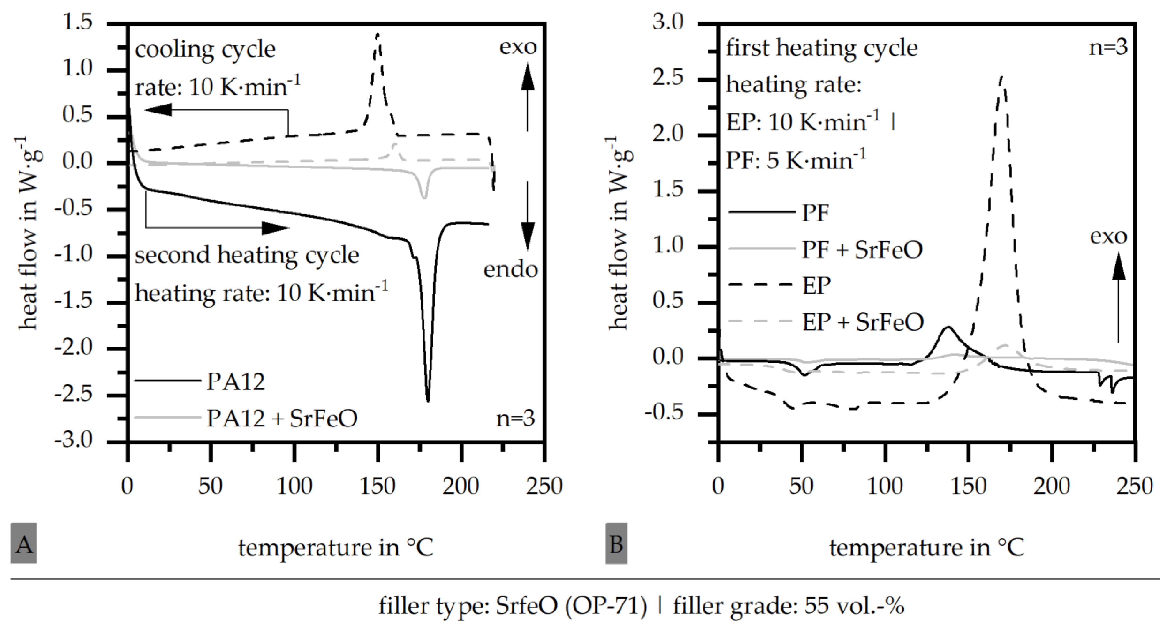
Differential scanning calorimetry (DSC 2500, TA Instruments, New Castle, DE, USA) was used to define the temperature dependent reaction kinetic of the compound. After placing samples of approximately 5 mg in the DSC aluminium, different heating rates were chosen in terms of the sensitivity of the materials towards temperature. Therefore, PA12 and EP was measured with a rate of 10 K per minute and PF with 5 K per minute. The measurements were measured from 0 °C to 220 °C in terms of PA12 and to 300 °C in terms of the two resins. For PA12, two heating cycles were realized. The experiments were performed in a nitrogen atmosphere with a flow rate of 50 mL per minute. To classify the heating process, the specific enthalpy, ΔHges, of the second heating cycle in terms of PA12 and of the first heating cycle in terms of the two resins as well as the corresponding peak temperature, Tpeak, was analysed. It has to be taken into account that in terms of a thermoplastic-based material system, the melting is an endothermal process, where Tpeak reveals the temperature at which most of the crystallites melt. However, polymers do not have a single melt temperature as metals do, but rather display a temperature field in which the melting occurs. Semi-crystalline thermoplastics display crystallites with different thickness of the lamellas. At the beginning of the melt peak, the first crystallites with a rather thin thickness of the lamellas start to melt. In the literature, the peak temperature, Tpeak, is commonly used to characterize the main part of the melting with respect to the fact that the melting expands over a broader temperature section [26]. In terms of thermosets, the curing process is exothermal and the peak temperature, Tpeak, indicates the setting, where most of the curing process is realized. However, the curing process starts at a lower temperature and is finished at a higher temperatures than Tpeak. This temperature is only a parameter to characterize the setting where most of the reaction takes place [11].
2.3.2. Determination of the Viscosity Using a Rotational Viscometer According to DIN EN 6043
The temperature dependence, and with that the dynamic viscosity behaviour, was defined using a rotational viscometer (Discovery Hybrid Rheometer 2, TA Instruments, New Castle, DE, USA) based on two plates with a shearing load. The frequency was kept constant at 1 Hz. In terms of the PA12 matrix material, the characterization took place between 280 °C and 150 °C, with a cooling rate of 5 K per minute. For the two resin types, the samples were analysed between 80 °C and 200 °C, with a heating rate of 5 K per minute. The different gradients of the temperature are based on the different chemical reaction mechanism of thermoplastics and thermosets. After reaching the starting set up, a shell was placed around the sample and the camber was floated with nitrogen. To define the viscosity behaviour, the minimum of the viscosity, ηmin, as well as the route, was analysed.
2.3.3. Determination of the Viscosity Using a High Pressure Capillary Rheometer According to DIN 54811 (Withdrawn by Now)
To define the viscosity under process conditions, the PA12-based compound was further analysed using a high pressure capillary rheometer (type: double capillary rheometer, Malvern Instruments Ltd., Malvern, UK). This characterization is not possible in terms of resin-based materials due to a curing during the measurement. The analyses were held at the three different temperature levels of 260 °C, 280 °C and 300 °C, with a shear rate between 102 and 104 s−1. In terms of the injection moulding process, the relevant shear rate of 103 and 104 s−1 is covered. The data were adjusted using the Rabinowitsch–Weissenberg method, and the route was analysed.
2.3.4. Mechanical Properties According to DIN EN ISO 527
The mechanical properties were based on bar-shaped samples, which were prepared out of plates with dimensions of 60 × 10 × 2 (mm3), with a milling machine. Due to the brittle behaviour of the resin-based samples, the preparation of tensile bars was not possible for all material set ups. A universal tensile testing machine (type: 1464, ZwickRoell GmbH & Co. KG, Ulm, Germany) with a traverse speed of 0.3 mm per minute was used to determine the mechanical properties under standard climate conditions of 23 °C and 50% relative humidity. In the case of the PA12-based materials, the samples were conditioned freshly moulded. The mechanical properties were characterized in terms of the stiffness or representative of the E-Modulus, Et, the tensile strength, σm, and the elongation at break, εm.
2.3.5. Magnetic Properties
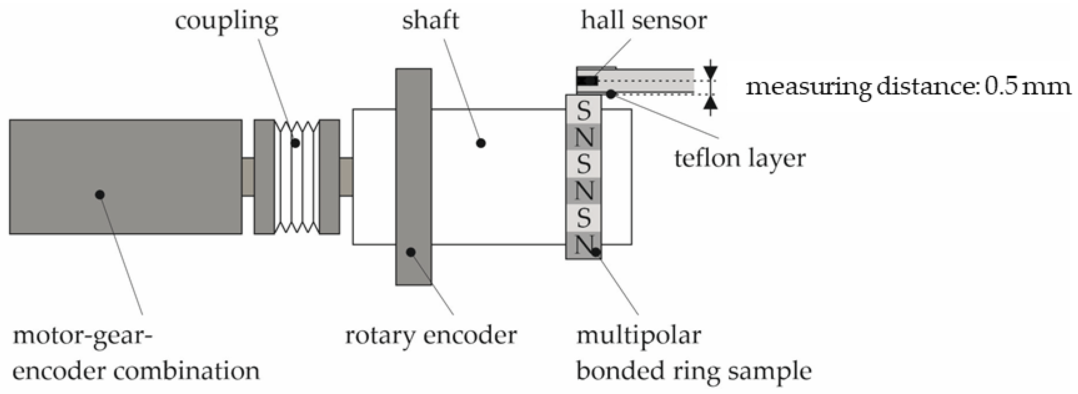
The magnetic properties were first defined before a final magnetization using a test rig, as shown in Figure 3. The samples were picked up by a clamping device at a defined position, and the route of the magnetic flux density relative to the angle of rotation was recorded by a hall sensor (Magnet-Physik Dr. Steingroever GmbH, Cologne, Germany) and a rotary encoder (Heidenhaim GmbH, Traunreut, Germany). The shaft with the sample was driven by a motor with a defined speed and number of revolutions.
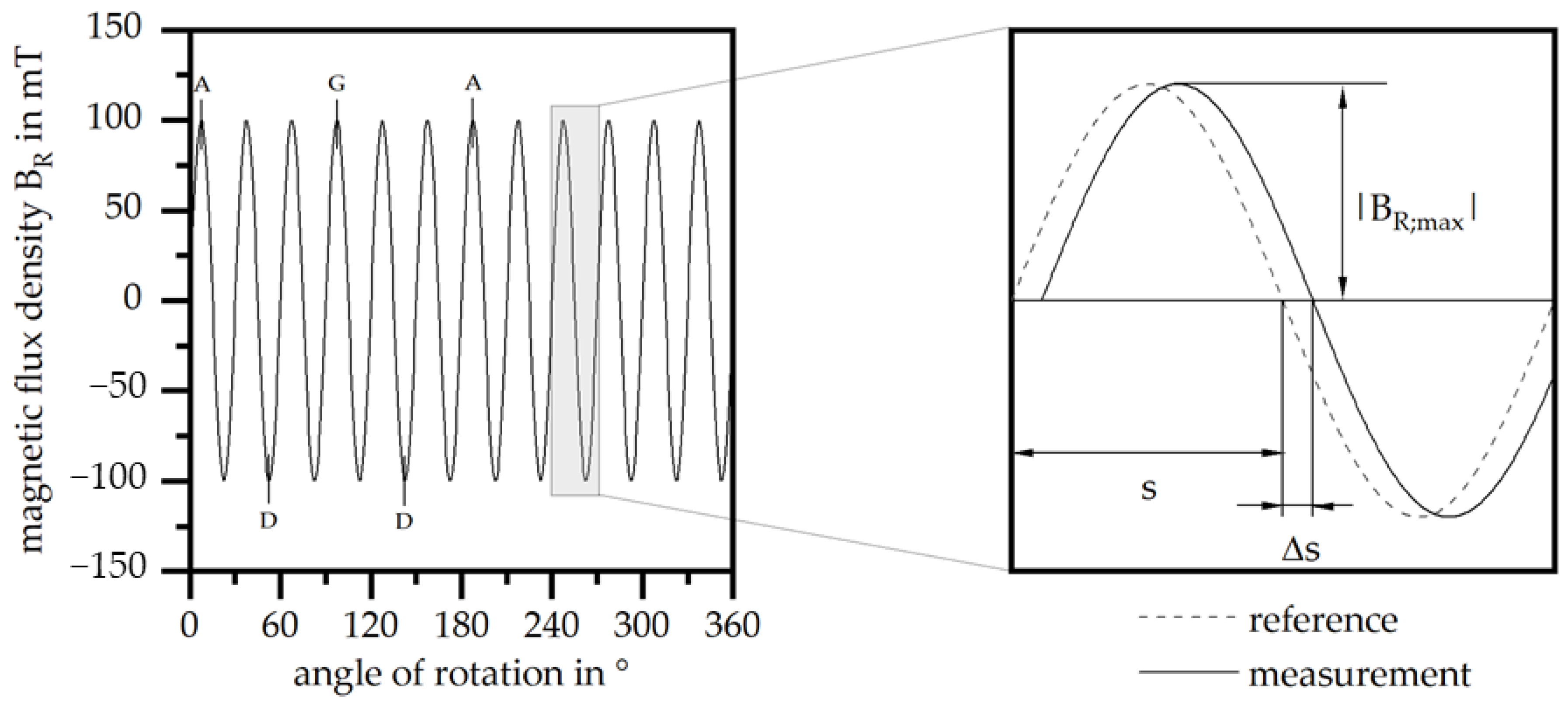
The ring sample was defined into 24 poles with 7 characteristic poles named A to G. With that, A represents the position of the gate and G the position of the weld line. Each peak of the flux density corresponds with one of the characteristic poles. Therefore, the magnetic properties were analysed in terms of the 7 characteristic poles and the maximum of the peak flux density, |BR;max|. Further, the pole accuracy was defined in terms of the shift of the pole angle, Δs. As the multipolar ring samples reveal 24 poles, the ideal pole angle is 15°. The real pole angle, s, is calculated between two zero crossings, and the difference to the ideal pole angle yields Δs. The correlation between the route of the flux density and the maximum of the peak flux density, |BR;max|, as well as the shift of the pole angles, Δs, at the characteristic poles is shown in Figure 4.
To define the maximum of the magnetic properties, samples with dimensions of 5 × 5 × 5 (cm3) were prepared at the characteristic poles A, D and G, with a milling machine. To ensure a final and full magnetization, a pulse magnetizer (type: Im-12220-U-MA-C, Magnet-Physik Dr. Steingroever GmbH, Cologne, Germany) and a magnetic device (type: MV D30 × 30 mm F-TC, Magnet-Physik Dr. Steingroever GmbH, Cologne, Germany) were used. After this step, the remanence, BR, was analysed with a permagraph (type: C-300, Magnet-Physik Dr. Steingroever GmbH, Cologne, Germany).
2.3.6. Filler Orientation
To analyse the orientation of the fillers, samples were prepared out of the multipolar bonded rings using a water-cooled saw with minimal temperature input. The samples were prepared in the region of pole A, near the gate, pole C and D, in the middle of the ring, and G, near the weld line. Further, the preparation was realized to analyse the orientation of the fillers in the middle of the sample width. The prepared samples were embedded in cold-curing epoxy resin (type: Epofix, Struers GmbH, Ottensoos, Germany) and polished. Afterwards, a stereo microscope (type: Axio Zoom.V16, Carl Zeiss AG, Oberkochen, Germany) was used to take images at different positions along the poles and the width. It has to be differed between the position relative to the pole at the pole pitch (position I to III), the middle of the pole (position i and ii) and the position along the width (position 1 to 5). Figure 5 depicts the preparation of the sample out of the multipolar bonded rings (A), the position relative to the pole (B to D) and the position relative to the width (E).
The images were separated between the matrix material and the filler by means of a grey-scale threshold analysis, and the main filler orientation between 0° and 90° was determined based on the longest axis of the individual particles.
3. Results
3.1. Reaction Kinetics According to Differential Scanning Calorimetry (DSC)
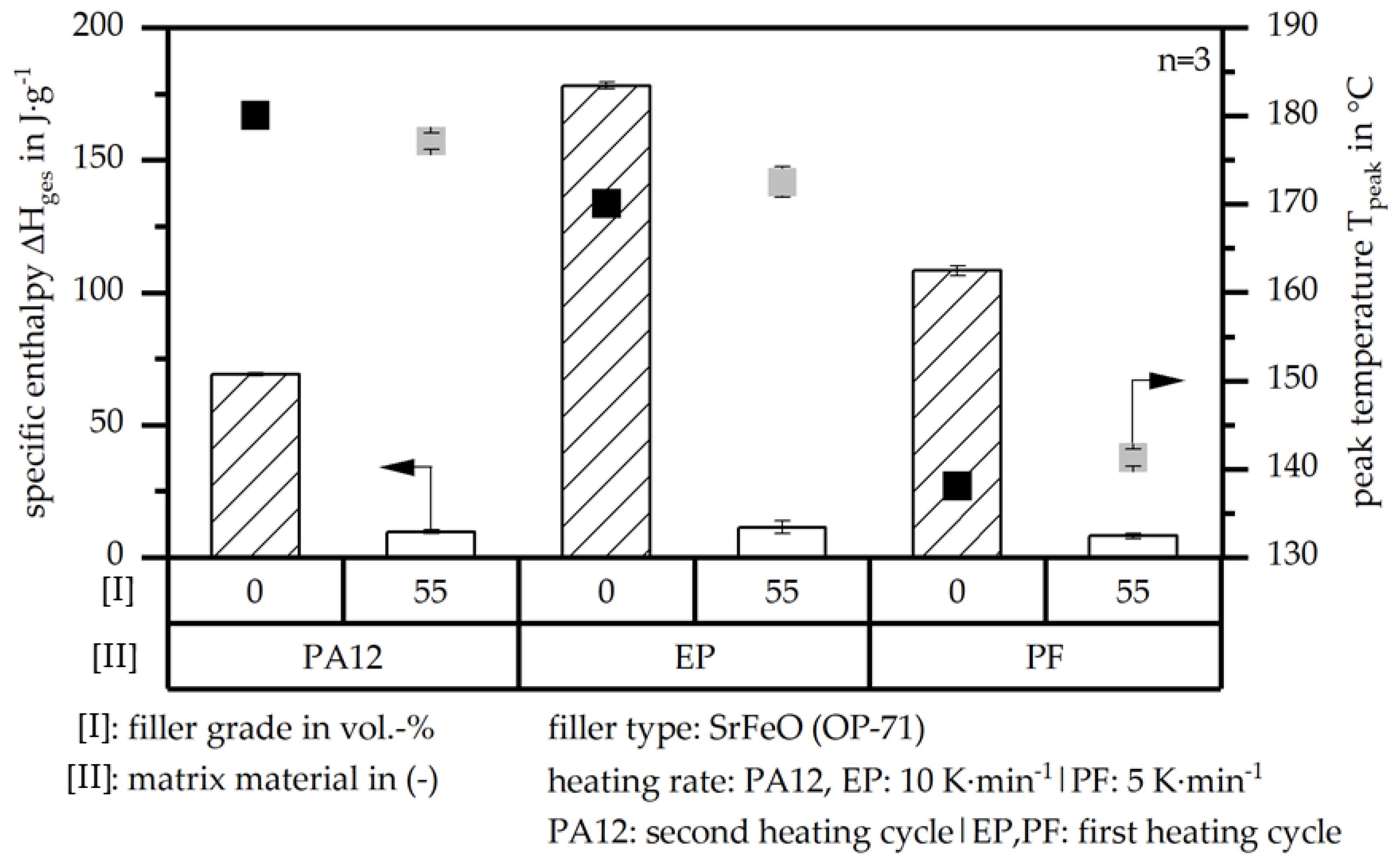
The characterization of the reaction kinetics of the different hard magnetic compounds in comparison to the pure matrix material can be realized with respect to the two parameters of the specific enthalpy, ΔHge, and the corresponding peak temperature, Tpeak, as shown in Figure 6. Further, the full DSC route of the materials is shown in Appendix A, Figure A1. The value of the specific enthalpy, ΔHges, is defined with the DSC measurements at the second heating cycle in terms of PA12-based compounds and at the first heating cycle with respect to the resin-based compounds. Due to the different reaction mechanisms, the heating rate changes throughout the matrix material. In general, ΔHges is significantly reduced in the filled systems compared to the unfilled ones as the filler itself is not reactive in the curing process and reduces the amount of material involved in the curing process. This leads to only a slight difference in ΔHges with respect to the different matrix materials in the filled systems. The peak temperature, Tpeak, is slightly increased within PA12-based compounds in comparison to the unfilled and filled compound, whereas it is reduced in terms of resin-based systems. The level of Tpeak is similar for the two matrix materials, PA12 and EP, as the heat capacity of these two materials is similar. The reduced Tpeak of PF compared to EP is reflected in the mould temperature of the processing conditions according to Table 3.
3.2. Viscosity According to a Rotational Viscometer
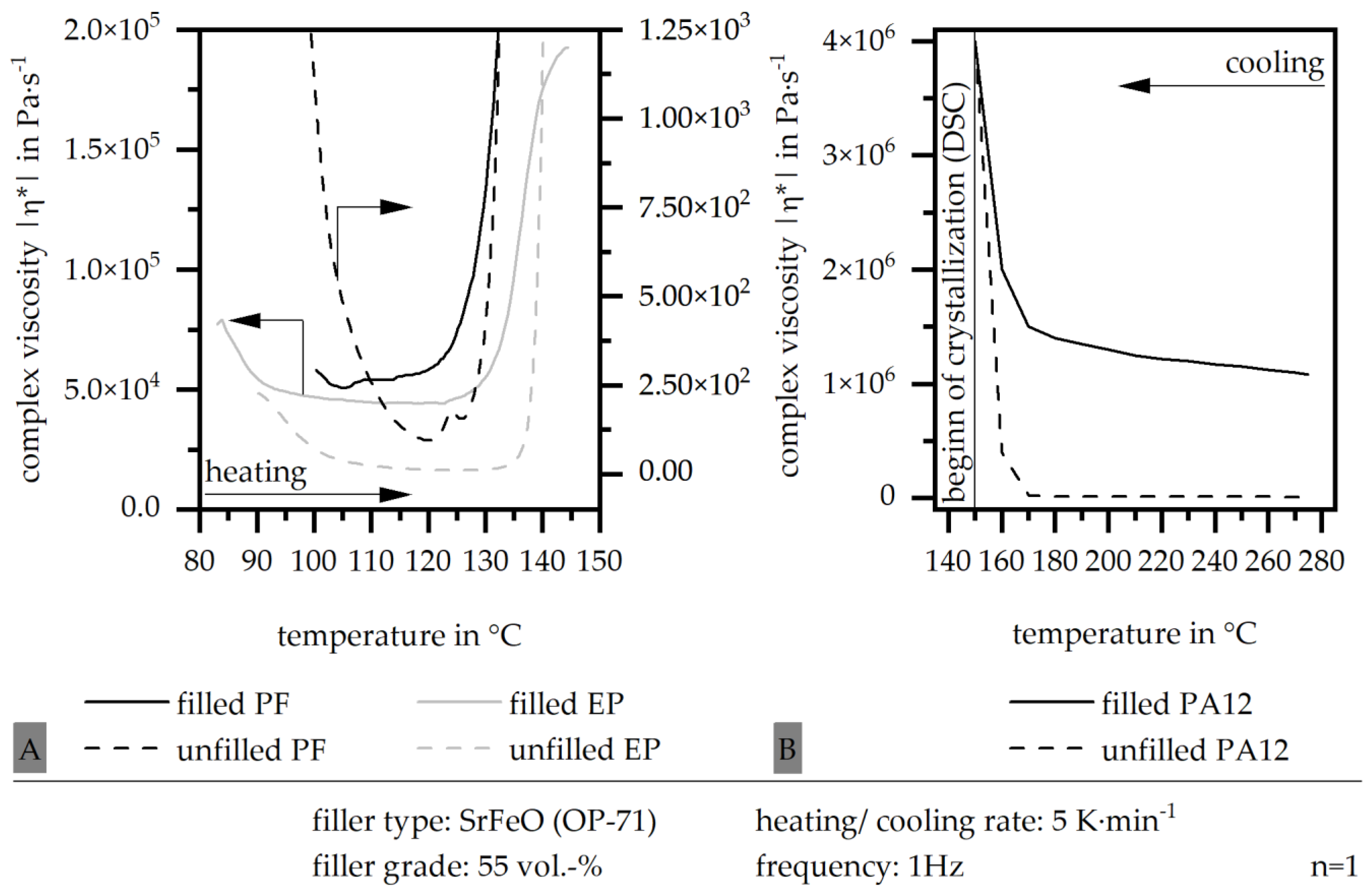
The viscosity based on the rotational viscometer is shown in Figure 7 with respect to the unfilled and filled hard magnetic compounds for the three different matrix materials EP, PF and PA12. The data were generated with a heating cycle in terms of the two resin systems and with a cooling cycle in terms of PA12-based systems, until the beginning of the crystallization has been reached. Is has to be taken into account that the scale of the data differs. In general, the minimum of the viscosity, ηmin, reaches a lower value in terms of the unfilled systems compared to the filled systems in each matrix system. In terms of the resin-based systems, the difference between the unfilled and filled systems is approximately four decades, with PF reaching slightly higher values compared to EP. Within PA12, the highest ηmin is gained, which is approximately 6 decades above the unfilled system and approximately 2 decades above the resin-based systems. With that, a lower viscosity in terms of resin-based hard magnetic compounds with respect to the filler SrFeO can be reached.
3.3. Viscosity According to a High-Pressure Capillary Rheometer
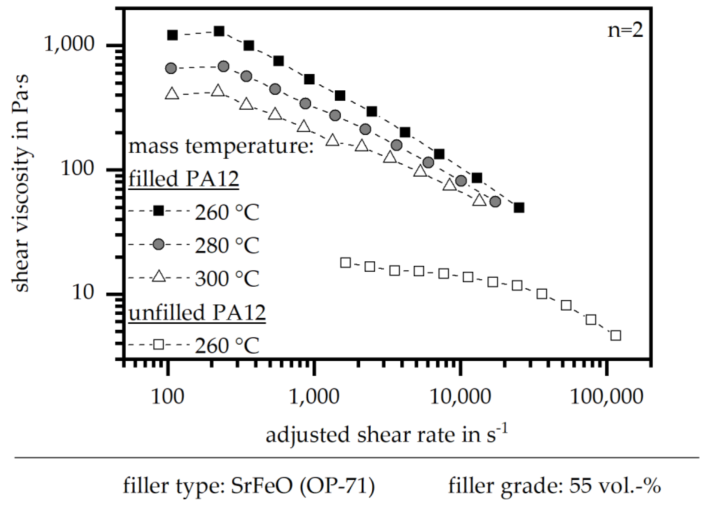
As the shear rate within a rotational viscometer is much lower compared to the injection moulding process, the viscosity has to be defined using a high-pressure capillary rheometer, where the approximated shear rate of the process can be reached between 103 and 104 s−1. However, the measurement conditions do not allow one to analyse thermoset-based materials in a high-pressure capillary rheometer. With that, Figure 8 only depicts the shear viscosity of PA12-based compounds. Again, the value of the viscosity increases in the filled system compared to the unfilled one, with a difference of approximately one and a half decades. Further, the viscosity decreases with higher temperature. It can be assumed that the gab of the minimum of the viscosity is reduced in terms of an unfilled and filled systems due to an increasing shear rate.
3.4. Mechanical Properties
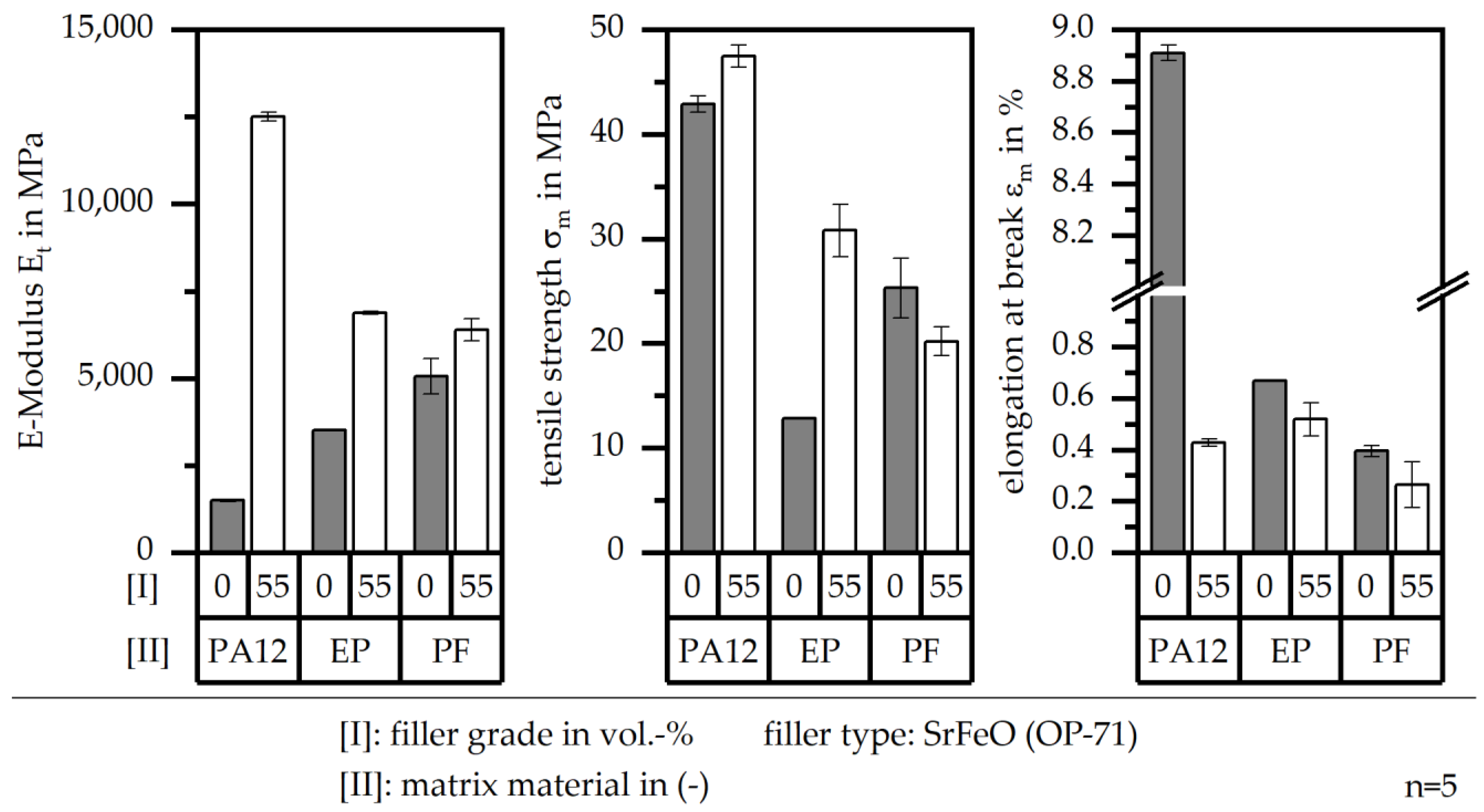
The mechanical properties can be evaluated in terms of the E-Modulus, Et, the tensile strength, σm, and the elongation at break, εm. Figure 9 shows the influence on these three parameters in terms of the matrix material (PA12, EP, PF), and in comparison to unfilled and filled systems. The E-Modulus, Et, is increased in terms of a filled system independent to the matrix material. However, Et in the thermoset-based systems is similar for the filled and the unfilled systems, whereas Et for the PA12-based system is much lower in the case of the unfilled and much higher in the case of the filled compound. The tensile strength, σm, is lower in terms of the resin-based systems compared to PA12. Due to the fillers, σm increases in terms of EP and PA12, but decreases for PF as a matrix material. This goes along with the network structure, which is displayed in [22] in detail. The elongation at break, εm, is decreased for filled systems relative to unfilled systems. Within resin-based systems, εm is much lower relative to unfilled PA12, which goes along with the brittle behaviour of thermosets. However, in the filled PA12 system, εm reaches almost the same value in terms of filled resin-based compounds.
3.5. Magnetic Properties
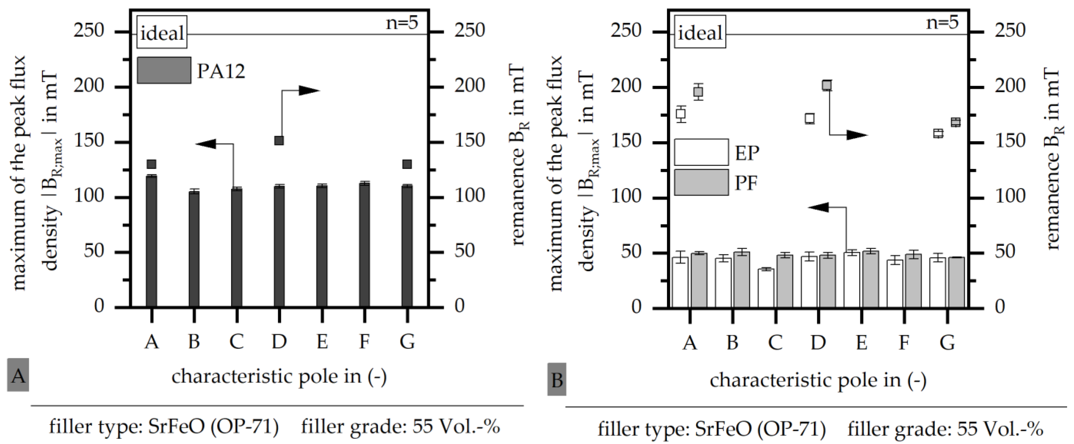
To define the magnetic properties, two different values of the flux density as well as the pole accuracy have to be evaluated. In terms of the flux density, the maximum of the peak flux density, |BR;max|, reveals the magnetic properties in terms of the orientation and part magnetization during the fabrication process. The remanence, BR, depicts the properties after a full magnetization using an impulse magnetizer. With that, the full potential of the material is analysed. Figure 10 depicts the two values of |BR;max| and BR at the characteristic poles for the filled material systems in terms of PA12 (A) and the two resin types (B) as a matrix material. In terms of PA12 matrix material, the difference between the magnetic properties before and after magnetization is similar, which leads to a high magnetization within the cavity during the injection moulding process. The values after magnetization reveal a small increase in terms of the characteristic pole D in the middle, relative to pole A at the gate and pole G at the weld line. The magnetic properties before magnetization are much lower for the two resin types compared to PA12 as a matrix. However, after magnetization these values increase significantly, reaching even higher values compared to PA12. Further, the magnetic properties can be improved in terms of PF as a matrix relative to EP. The values slightly decreased at the characteristic pole G relative to poles A and D. With respect to the ideal magnetic properties, as shown in Figure 10, in terms of the filler grade, the resin-based systems reach 80%, whereas thermoplastic-based systems reach only 60%. This allows a higher usage of the material potential in terms of thermoset-based multipolar bonded magnets.
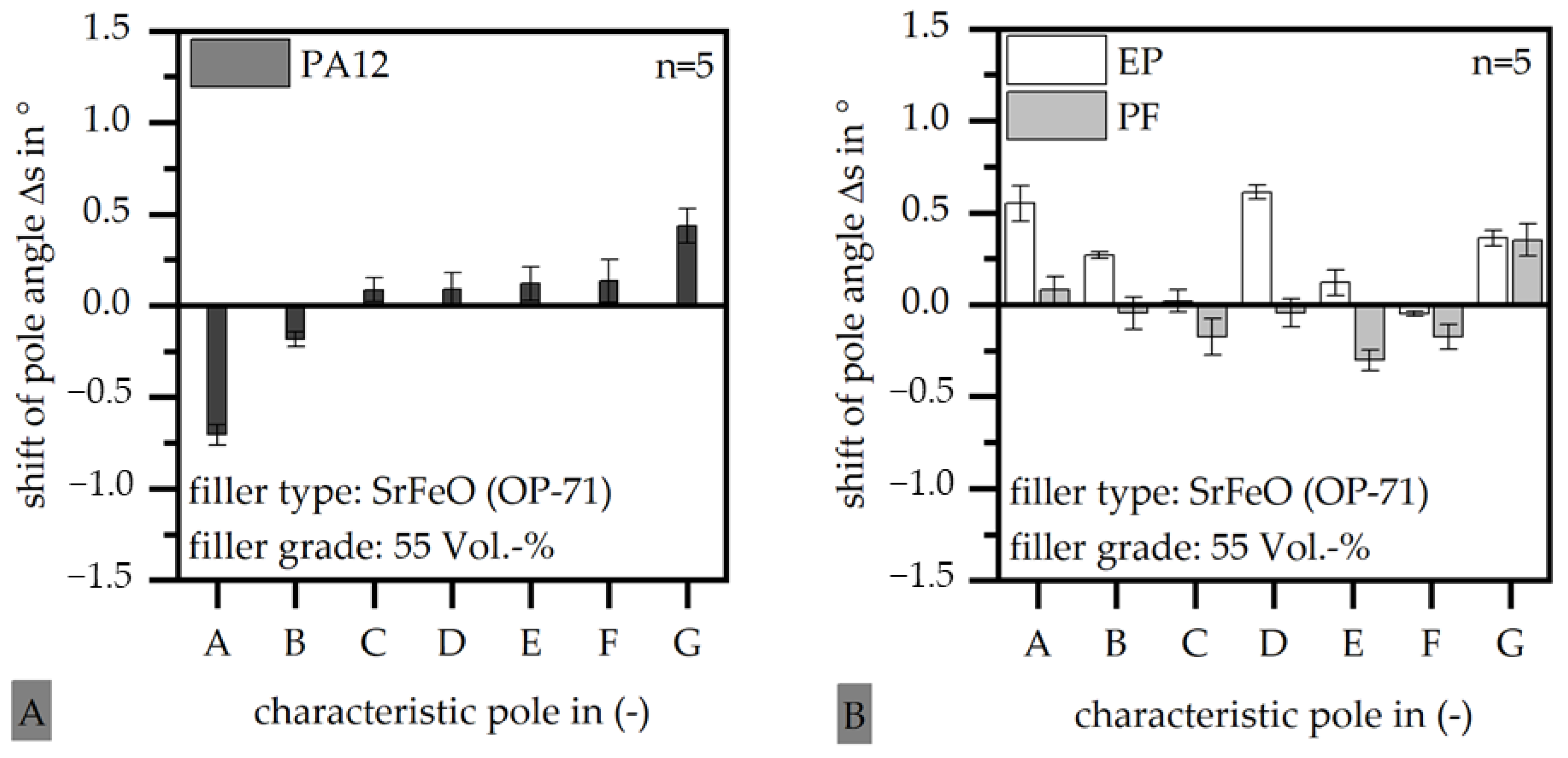
Besides the flux density, the pole accuracy is used to define the magnetic properties. Figure 11 depicts the pole accuracy at the characteristic poles in terms of filled systems with a PA12 matrix (A) and a resin-based matrix (B). In terms of a PA12 matrix, the shift of the pole angle, Δs, is increased at the characteristic poles A and G, but is low in between. In terms of EP-based systems, Δs is similar in its maximal values relative to PA12, but higher relative to PF. For PF-based systems, Δs is significant at position G at the weld line, but negligible for the other positions.
3.6. Filler Orientation
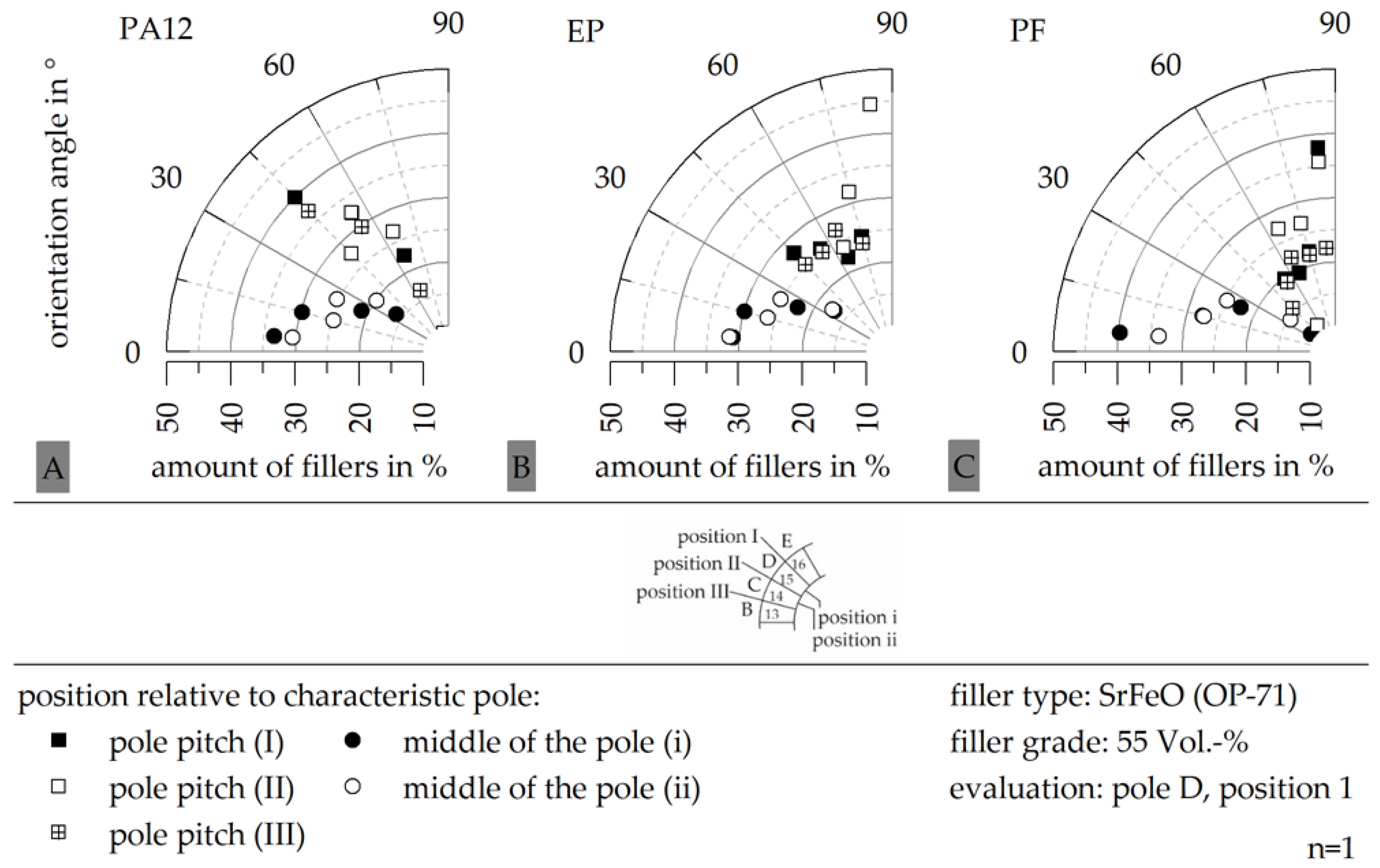
The filler orientation at the characteristic pole D and position 1 relative to the sample width (on the outer diameter) is shown in Figure 12 in terms of different positions around the characteristic pole and for the three different matrix materials, PA12 (A), EP (B) and PF (C), with the filler type SrFeO and a constant filler grade of 55 vol.-%. Due to the outer magnetic field, the orientation angle should be 90° in terms of the pole pitch and 0° in terms of the middle of the pole. Further, the difference in the orientation angle within one position (either pole pitch or middle of the pole) should be as small as possible. In terms of a PA12-based system, the orientation in the pole pitch reaches only 45°, whereas PF-based systems reach 90°. EP-based systems reach an orientation of 90° in the pole pitch I, but have a reduced orientation in positions II and III of only 60°. Further, PF-based systems reach a higher homogeneity in the middle of the pole compared to PA12.
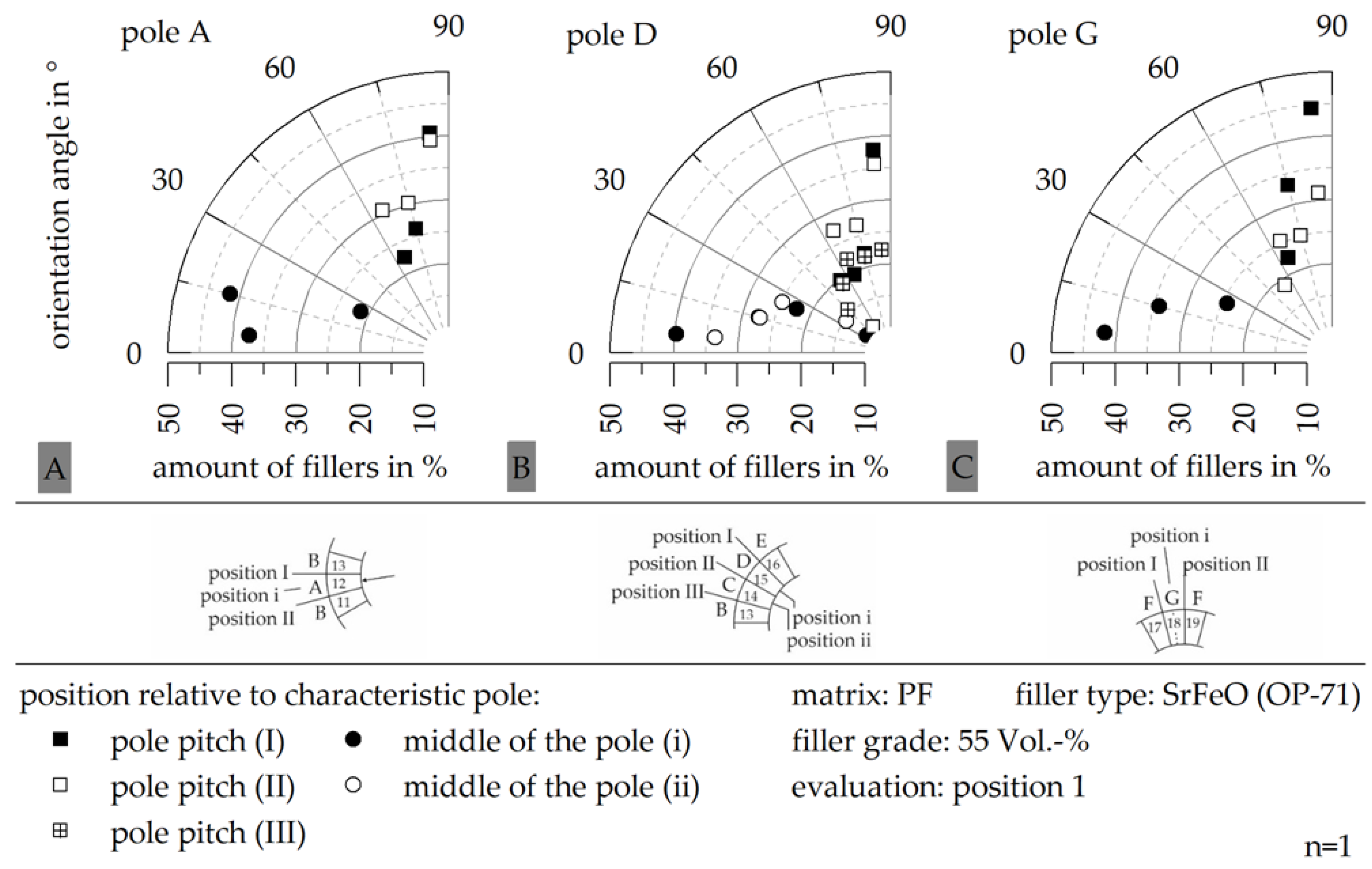
The influence of the characteristic pole on the filler orientation is depicted in Figure 13, exemplary for the matrix material PF at position 1 relative to the sample width. The orientation is slightly reduced in terms of the characteristic pole G at the weld line, where a higher stray field at the pole pitch is reached.
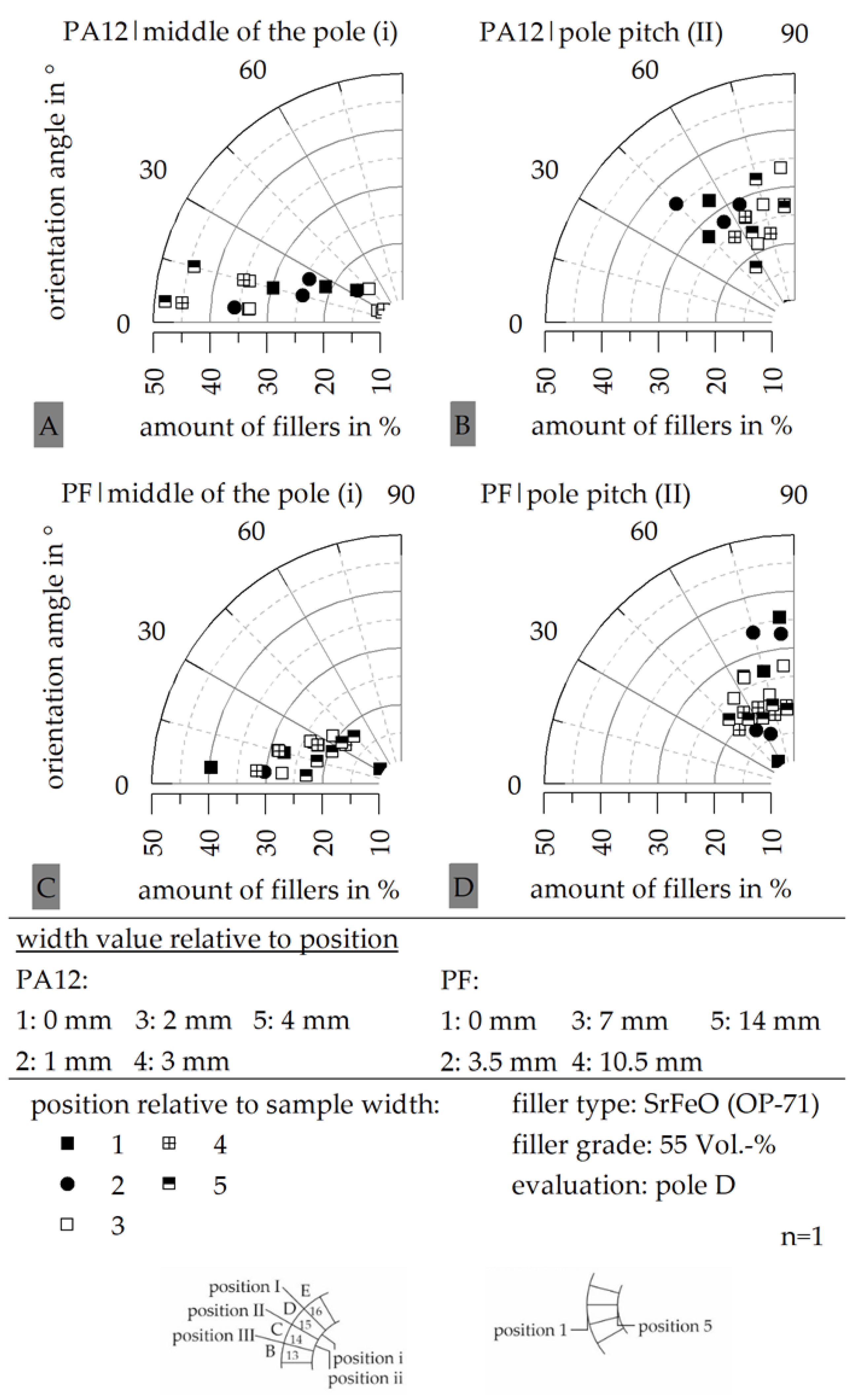
Further, the influence of the position relative to the sample width on the filler orientation has been investigated, as shown in Figure 14, to see the differences of the impact along the width of the sample with respect to the different matrix materials, exemplary for PA12 and PF. In terms of PF-based systems, the filler orientation is highly reduced, with a width greater than 7 mm. This goes along with a reduced strength of the outer magnetic field in the inside of the cavity. In terms of PA12-based systems, the orientation is improved with reaching a position near the inner diameter due to the flow conditions, as shown in [12]. This depicts the different flow conditions and reaction kinetics reached in the thermoplastic- or thermoset-based materials.
4. Discussion
The usage of a different matrix material in polymer-bonded magnets leads to a significant change in the reaction kinetics and viscosity behaviour, which has a high impact on the magnetic and mechanical properties. This correlation was shown within the investigation. The reaction kinetics show a similar behaviour in terms of the value of ΔHges for the three matrix systems as well as Tpeak for PA12 and EP. With that, almost the same amount of enthalpy is needed in the process. However, the time setting is completely different in the thermoplastic- and thermoset-based compounds. The definition of the viscosity for both types of matrix materials is difficult, as the viscosity according to a high-pressure capillary rheometer cannot be defined in terms of a thermoset-based system. With that, the comparison between the viscosity of thermoplastic- and thermoset-based systems can only be realized in terms of a rotational viscometer, which does not correspond to the actual shear rates in the process. However, filled systems based on PA12 reveal a viscosity which is approximately 6 decades higher relative to EP or PF. Further, the viscosity of PF is slightly higher compared to EP. Even if the shear rate does not completely reply to the setting of the fabrication in the injection moulding process, thermoset-based compounds reveal a significantly lower viscosity, which should have a positive effect on the orientation of the hard magnetic fillers and with that on the magnetic properties.
The magnetic properties display that the potential of the thermoset-based systems can only be used if a full magnetization after the fabrication process is ensured. Due to the high temperatures in the mould during the injection moulding process of thermosets, the strength of the outer magnetic field in the cavity is reduced. As the mould temperature is much lower in terms of the thermoplastic-based system, the reduction is only slightly present. If full magnetization after the fabrication is ensured, the potential of the thermoset-based samples in terms of magnetic properties is higher relative to thermoplastic-based systems. In thermoset-based systems, approximately 80% of the ideal magnetic properties can be reached, whereas in thermoplastic-based compounds only 60% can be reached. This change in the usage of the potential magnetic properties goes along with the level of the viscosity reached by each matrix material. As PF-based systems reach the lowest viscosity, the magnetic properties show the greatest level. This further goes along with the orientation reached in the different material systems. Due to the lower viscosity in terms of thermoset-based systems, the orientation in the middle of the pole and the pole pitch is almost exactly the same structure as the outer magnetic field at the outer diameter (reaching 0° in the middle of the pole and 90° in the pole pitch). In terms of thermoplastic-based systems, the orientation in the pole pitch reaches only 45°. This reduction of the orientation in terms of thermoplastic-based systems is not only influenced by the viscosity but is also related to the fast cooling outer coat with respect to [12]. In thermoset-based systems, this fast cooling outer coat does not take place, leading to a two-phase orientation with a region of orientation due to the outer magnetic field (from the outer diameter to the middle of the sample) and a second region towards the inner diameter, where the outer magnetic field strength is too low in terms of the temperature-driven reduction of the magnetic properties. As the system is mainly influenced by the outer magnetic field with respect to the orientation and not disturbed by partly shear induced orientation, the low viscosity can be used to improve the orientation, and with that the magnetic properties, in terms of thermoset-based systems.
The pole accuracy reveals a slight improvement at the position of the gate (characteristic pole A) in terms of the thermoset-based material. Further, the pole accuracy is significantly higher in terms of PF-based systems. Due to the low viscosity in the thermoset-based systems and the flow conditions, the pole accuracy is improved relative to thermoplastic systems for the characteristic poles B to F, but reveal a similar behaviour in both matrix types for the characteristic poles A (gate) and G (weld line).
Besides the magnetic properties, the mechanical properties are further important in terms of the sample properties and possible applications. The thermoset-based systems reveal approximately 50% of the stiffness and the strength relative to thermoplastic-based compounds, but show almost the same brittle behaviour in filled systems. The reduction of Et and σm has to be evaluated in terms of the demands in the application. If higher stiffness or strength is needed in terms of the applications for multipolar bonded magnets, a modification of thermoset-based systems can be discussed. With the matrix materials investigated in this paper, the thermoset-based systems show a significant improvement in the magnetic properties, which goes along with the flow conditions and a low viscosity. The usage of thermoset-based systems leads, on the other hand, to reduction of the mechanical properties in terms of the stiffness and the strength relative to thermoplastic-based systems.
5. Conclusions
The presented investigations show the different behaviour in multipolar bonded magnets with SrFeO as a hard magnetic filler with a constant filler grade of 55 vol.-% and a changing matrix system. Mainly, the impact of the variation of the matrix material onto the mechanical and magnetic properties are revealed with respect to the material characterization. It was shown that the magnetic properties reach higher values in terms of thermoset-based systems after ensuring a full magnetization. This effect goes along with a lower viscosity in thermoset-based compounds as well as different flow conditions, which allow an orientation only due to the outer magnetic field as long as the strength is not too week due to the high temperature in the mould. With that, the mechanism of the orientation in thermoset-based systems is significantly varying relative to the thermoplastic ones, where a fast cooling outer coat and a partly shear induced orientation takes place. Besides the improvement of the magnetic properties, the mechanical properties—specifically the stiffness and the strength—are reduced using a thermoset-based system. The impact of this reduction has to be evaluated in terms of the demand in each application.
Author Contributions
U.R., conceptualization, methodology, validation, investigation, writing—original draft preparation, visualization; D.D., writing—review and editing, supervision, project administration, funding acquisition. All authors have read and agreed to the published version of the manuscript.
Funding
This research was funded by the German Research Foundation (DFG) within the project DFG DR 412/36-1 “Duroplastgebundene spritzgegossene Dauermagneten mit definierter Magnetisierungsstruktur”. We acknowledge financial support by Deutsche Forschungsgemeinschaft and Friedrich-Alexander-Universität Erlangen-Nürnberg within the funding programme “Open Access Publication Funding”.
Data Availability Statement
Restrictions apply to the availability of these data. Data are available with the permission of the author.
Acknowledgments
We want to thank the German Research Foundation (DFG) for funding the project DFG DR 421/36-1 “Duroplastgebundene spritzgegossene Dauermagneten mit definierter Magnetisierungsstruktur” as well as Friedrich-Alexander-Universität Erlangen-Nürnberg for the funding programme “Open Access Publication Funding”.
Conflicts of Interest
The authors declare no conflict of interest. The funders had no role in the design of the study; in the collection, analyses or interpretation of data; in the writing of the manuscript or in the decision to publish the results.
Appendix A
Figure A1.
Route of the DSC measurement of unfilled and filled (SrFeO, 55 vol.-%) hard magnetic compound with different matrix material (PA12 (A); EP, PF (B)).
Figure A1.
Route of the DSC measurement of unfilled and filled (SrFeO, 55 vol.-%) hard magnetic compound with different matrix material (PA12 (A); EP, PF (B)).

References
- Cassing, W.; Kuntze, K.; Ross, G. Dauermagnete: Mess- und Magnetisierungstechnik, 3rd ed.; Expert-Verlag: Renningen, Germany, 2018. [Google Scholar]
- Drummer, D. (Ed.) Prozessführung Beim Spritzgießen Kunststoffgebundener Dauermagnete; Springer: Berlin/Heidelberg, Germany, 2004. [Google Scholar]
- Johannaber, F.; Michaeli, W. Handbuch Spritzgießen, 2nd ed.; Carl Hanser Verlag: München, Germany, 2004. [Google Scholar]
- Ormerod, J.; Constantinides, S. Bonded permanent magnets: Current status and future opportunities (invited). J. Appl. Phys. 1997, 818, 4816–4820. [Google Scholar] [CrossRef] [Green Version]
- Reppel, G.W. Duroplastgepresste Magnete—Werkstoffe, Verfahren und Eigenschaften. In Kunststoffgebundene Dauermagnete: Werkstoffe, Fertigungsverfahren und Eigenschaften; Ehrenstein, G.W., Drummer, D., Eds.; Springer VDI: Düsseldorf, Germany, 2004; pp. 14–36. [Google Scholar]
- Lagorce, L.; Allen, M. Magnetic and mechanical properties of micromachined strontium ferrite/polyimide composites. J. Mircoelectromechanical Syst. 1997, 6, 307–312. [Google Scholar] [CrossRef] [Green Version]
- Kurth, K.; Drummer, D. Improvement of the magnetic properties of injection molded polymer bonded magnets. In Proceedings of the 2013 3rd International Electric Drives Production Conference (Edpc), Nuremberg, Germany, 29–30 October 2013; pp. 1–5. [Google Scholar]
- Hagemann, B. Kunststoffgebundene Magnete in der Antriebstechnik—Möglichkeiten und Grenzen. In Kunststoffgebundene Dauermagnete; Springer VDI: Düsseldorf, Germany, 2004. [Google Scholar]
- Gardocki, A.; Drummer, D. Improvement of the filler orientability during injection molding of Multi polar SmCo Magnets by Premagnetization. In Proceedings of the 2nd International Electric Drives Production Conference (EDPC), Nuremberg, Germany, 15–18 October 2012. [Google Scholar]
- Schliesch, T. Kunststoffgebundener Rotor für Gleichstrommotoren mit unterschiedlichen Werkstoffen und Feldbereichen. In Kunststoffgebundene Dauermagnete; Springer VDI: Düsseldorf, Germany, 2004; pp. 68–88. [Google Scholar]
- Baur, E.; Brinkmann, S.; Osswald, T.; Rudoplh, N.; Schmachtenberg, E. Saechtling Kunststoff Taschenbuch, 31st ed.; Carl Hanser Verlag: München, Germany, 2013. [Google Scholar]
- Kurth, K. Zum Spritzgießen Polorientierter Kunststoffgebundener Dauermagnete. Ph.D. Dissertation, Friedrich-Alexander-Universität Erlangen-Nürnberg, Erlangen, Germany, 2019. [Google Scholar]
- Hering, E.; Martin, R.; Stohrer, M. Physik Für Ingenieure, 12th ed.; Springer Vieweg: Berlin, Germany, 2016. [Google Scholar]
- Ma, B.; Sun, A.; Gao, X.; Bao, X.; Li, J.; Lang, H. Preparation of anisotropic bonded NdFeB/SmFeN hybrid magnets by mixing two powders. J. Magn. Magn. Mater. 2018, 457, 70–74. [Google Scholar] [CrossRef]
- Qin, W.; He, J.; Yao, L. Research on the molding technology of bonded NdFeB Magnets. Appl. Mech. Mater. 2012, 217–219, 1815–1818. [Google Scholar] [CrossRef]
- Duan, B.; Qu, X.; Xu, Z.-Z.; Guo, Y.; Qin, M.-I. Injection molding bonded NdFeB magnet with high magnetic properties. Chin. J. Nonferrous Met. 2004, 9, 1653. [Google Scholar]
- Eimeke, S. Spritzgießen Multipolarer, Kunststoffgebundener Dauermagnete. Ph.D. Dissertation, Friedrich-Alexander-Universität Erlangen-Nürnberg, Erlangen, Germany, 2008. [Google Scholar]
- Maenz, T. Spritzgießtechnische Herstellung Duroplastgebundener Dauermagnete. Ph.D. Dissertation, Technische Universität, Chemnitz, Germany, 2018. [Google Scholar]
- Ohmori, K.; Hayashi, S.; Yoshizawa, S. Injection-molded Sm-Fe-N anisotropic magnets using unsaturated polyester resin. J. Alloys Conpounds 2006, 408, 1359–1362. [Google Scholar] [CrossRef]
- Zhang, H.W.; Hu, B.P.; Han, Z.F.; Jin, H.M.; Fu, Q. Magnetic Properties of NdFe10Mo2N Bonded Magnets. Phys. Status Solidi (A) 1997, 161, 469–474. [Google Scholar] [CrossRef]
- Rösel, U.; Drummer, D. Correlation between the Flow and Curing Behavior of Hard Magnetic Fillers in Thermosets and the Magnetic Properties. Magnetism 2021, 1, 37–57. [Google Scholar] [CrossRef]
- Rösel, U.; Drummer, D. Understanding the effect of material parameters on the processability of injection-molded thermosets-based bonded Magnets. Magnetism 2022, 2, 211–228. [Google Scholar] [CrossRef]
- Stitz, S.; Keller, W. Spritzgießtechnik: Verarbeitung, Maschine, Peripherie, 2nd ed.; Hanser: München, Germany, 2004. [Google Scholar]
- Kurth, K.; Drummer, D. Variation of the Pole Length in Pole-Oriented Bonded Rings due to the Location and Number of Injection Points. J. Polym. 2017, 2017, 824185. [Google Scholar] [CrossRef] [Green Version]
- Hoven-Nievelstein, W. Wir bewegen uns in Richtung Spezialitäten, Kunststoffe—Werkstoffe, Verarbeitung. Anwendung 2008, 6, 24–29. [Google Scholar]
- Ehrenstein, G.W.; Riedel, G.; Trawiel, P. Praxis der Thermischen Analyse von Kunststoffen, 2nd ed.; Carl Hanser Verlag: München, Germany, 2003. [Google Scholar]
Figure 1.
Model of the orientation (A) and pole accuracy (B) in thermoplastic-based multipolar polymer bonded magnets with a ring structure (after [12]).
Figure 1.
Model of the orientation (A) and pole accuracy (B) in thermoplastic-based multipolar polymer bonded magnets with a ring structure (after [12]).

Figure 2.
Multipolar bonded ring sample with 24 poles and definition of 7 characteristic poles (A to G), relative to the position of the gate and the weld line.
Figure 2.
Multipolar bonded ring sample with 24 poles and definition of 7 characteristic poles (A to G), relative to the position of the gate and the weld line.

Figure 3.
Test rig for evaluation of the multipolar bonded ring samples with respect to the magnetic flux density relative to the angle of rotation.
Figure 3.
Test rig for evaluation of the multipolar bonded ring samples with respect to the magnetic flux density relative to the angle of rotation.

Figure 4.
Route of magnetic flux density relative to angle of rotation with characteristic poles [for example: A, D, G] as well as maximum of the peak flux density, |BR;max|, and shift of pole angle, Δs.
Figure 4.
Route of magnetic flux density relative to angle of rotation with characteristic poles [for example: A, D, G] as well as maximum of the peak flux density, |BR;max|, and shift of pole angle, Δs.

Figure 5.
Preparation of the samples for definition of the filler orientation out of multipolar rings (A), position relative to the pole (B–D) and position relative to the width (E).
Figure 5.
Preparation of the samples for definition of the filler orientation out of multipolar rings (A), position relative to the pole (B–D) and position relative to the width (E).

Figure 6.
Reaction kinetics of unfilled and filled (SrFeO, 55 vol.-%) hard magnetic compounds with different matrix materials (PA12, EP, PF) based on DSC measurement.
Figure 6.
Reaction kinetics of unfilled and filled (SrFeO, 55 vol.-%) hard magnetic compounds with different matrix materials (PA12, EP, PF) based on DSC measurement.

Figure 7.
Viscosity of unfilled and filled (SrFeO, 55 vol.-%) hard magnetic compounds with different matrix material (PA12 (A); EP, PF (B)) based on rotational viscometer.
Figure 7.
Viscosity of unfilled and filled (SrFeO, 55 vol.-%) hard magnetic compounds with different matrix material (PA12 (A); EP, PF (B)) based on rotational viscometer.

Figure 8.
Viscosity of unfilled and filled (SrFeO, 55 vol.-%) hard magnetic compounds (matrix material: PA12) based on high pressure capillary rheometer.
Figure 8.
Viscosity of unfilled and filled (SrFeO, 55 vol.-%) hard magnetic compounds (matrix material: PA12) based on high pressure capillary rheometer.

Figure 9.
Mechanical properties of multipolar bonded ring sample based on unfilled and filled (SrFeO, 55 vol.-%) hard magnetic compound with different matrix material (PA12, EP, PF).
Figure 9.
Mechanical properties of multipolar bonded ring sample based on unfilled and filled (SrFeO, 55 vol.-%) hard magnetic compound with different matrix material (PA12, EP, PF).

Figure 10.
Magnetic properties of multipolar bonded ring sample based on filled (SrFeO, 55 vol.-%) hard magnetic compound with different matrix material (PA12 (A); EP, PF (B)).
Figure 10.
Magnetic properties of multipolar bonded ring sample based on filled (SrFeO, 55 vol.-%) hard magnetic compound with different matrix material (PA12 (A); EP, PF (B)).

Figure 11.
Pole accuracy of multipolar bonded ring sample based on filled (SrFeO, 55 vol.-%) hard magnetic compound with different matrix material (PA12 (A); EP, PF (B)).
Figure 11.
Pole accuracy of multipolar bonded ring sample based on filled (SrFeO, 55 vol.-%) hard magnetic compound with different matrix material (PA12 (A); EP, PF (B)).

Figure 12.
Filler orientation in the characteristic pole D at different positions (pole pitch, middle of the pole) at position 1 relative to the width for the filled system with different matrix materials (PA12 (A), EP (B), PF (C)).
Figure 12.
Filler orientation in the characteristic pole D at different positions (pole pitch, middle of the pole) at position 1 relative to the width for the filled system with different matrix materials (PA12 (A), EP (B), PF (C)).

Figure 13.
Filler orientation in the characteristic poles A (A), D (B) and G (C) at different positions (pole pitch, middle of the pole) at position 1 relative to the width for the filled system based on PF.
Figure 13.
Filler orientation in the characteristic poles A (A), D (B) and G (C) at different positions (pole pitch, middle of the pole) at position 1 relative to the width for the filled system based on PF.

Figure 14.
Filler orientation in the characteristic pole D at two positions relative to the characteristic pole (pole pitch, middle of the pole) at different position relative to the width for the filled system and the matrix material PA12 (A,B) as well as PF (C,D).
Figure 14.
Filler orientation in the characteristic pole D at two positions relative to the characteristic pole (pole pitch, middle of the pole) at different position relative to the width for the filled system and the matrix material PA12 (A,B) as well as PF (C,D).


Table 1.
Specification of the matrix material including density, φ, heat capacity, c, and peak temperature, Tpeak (own measurements) as well as thermal conductivity, λ (manufacturer specifications).
Table 1.
Specification of the matrix material including density, φ, heat capacity, c, and peak temperature, Tpeak (own measurements) as well as thermal conductivity, λ (manufacturer specifications).
| Matrix Material | Density φ in g∙cm−3 | Heat Capacity c in J∙g−1∙°C−1 | Thermal Conductivity λ in W∙m−1∙K−1 | Peak Temperature Tpeak in °C |
|---|---|---|---|---|
| Polyamide 12 (PA12) | 1.000 | 1.840 | 0.23 | 180.1 (1) |
| Epoxy resin (EP) | 1.225 | 1.616 | 0.4–0.6 | 170.1 (1) |
| Phenolic resin (PF) | 1.292 | 1.294 | 0.4–0.6 | 138.1 (2) |
DSC: (1): 10 K∙min−1|(2): 5 K∙min−1.
Table 2.
Specification of the hard magnetic filler material including density, φ, heat capacity, c, thermal conductivity, λ, and mean particle size, d50 (own measurements).
Table 2.
Specification of the hard magnetic filler material including density, φ, heat capacity, c, thermal conductivity, λ, and mean particle size, d50 (own measurements).
| Filler Material | Density φ in g∙cm−3 | Heat Capacity c in J∙g−1∙°C−1 | Thermal Conductivity λ in W∙m−1∙K−1 | Mean Particle Size d50 in µm | |
|---|---|---|---|---|---|
| Numerical | Volumetric | ||||
| SrFeO | 5.380 | 0.639 | 2.3 | 4.87 | 1.94 |
Table 3.
Process conditions of the fabrication of ring samples and plates with differentiation between the three matrix materials: PA12, EP and PF.
Table 3.
Process conditions of the fabrication of ring samples and plates with differentiation between the three matrix materials: PA12, EP and PF.
| Matrix Material | PA12 | EP | PF | ||
|---|---|---|---|---|---|
| Sample Type | Ring/Plate | Ring | Plate | Ring | Plate |
| Process Conditions | |||||
| mass temperature, Tm in °C | 280 | 85 | 85 | 85 | 85 |
| mould temperature, TWZ in °C | 80 | 190 | 200 | 180 | 180 |
| holding pressure, ph in bar | 500 | 650 | 250 | 650 | 250 |
| heating time, th in s | - | 200 | 300 | 45 | 120 |
| injection speed, vin in mm∙s−1 | 40 | 15 | 15 | 15 | 15 |
Disclaimer/Publisher’s Note: The statements, opinions and data contained in all publications are solely those of the individual author(s) and contributor(s) and not of MDPI and/or the editor(s). MDPI and/or the editor(s) disclaim responsibility for any injury to people or property resulting from any ideas, methods, instructions or products referred to in the content. |
© 2023 by the authors. Licensee MDPI, Basel, Switzerland. This article is an open access article distributed under the terms and conditions of the Creative Commons Attribution (CC BY) license (https://creativecommons.org/licenses/by/4.0/).
Share and Cite
MDPI and ACS Style
Rösel, U.; Drummer, D. Extension of the Application Range of Multipolar Bonded Ring Magnets by Thermosets in Comparison to Thermoplastics. Magnetism 2023, 3, 71-89. https://doi.org/10.3390/magnetism3010007
AMA Style
Rösel U, Drummer D. Extension of the Application Range of Multipolar Bonded Ring Magnets by Thermosets in Comparison to Thermoplastics. Magnetism. 2023; 3(1):71-89. https://doi.org/10.3390/magnetism3010007
Chicago/Turabian StyleRösel, Uta, and Dietmar Drummer. 2023. "Extension of the Application Range of Multipolar Bonded Ring Magnets by Thermosets in Comparison to Thermoplastics" Magnetism 3, no. 1: 71-89. https://doi.org/10.3390/magnetism3010007