Article

Monopole Antenna Miniaturization with Magneto-Dielectric Material Loading Combined with Metal Parasitic Element

1
Institut d’Electronique et des Technologies du Numérique (IETR), University of Rennes 1, 35000 Rennes, France
2
Directorate General of Armaments (DGA), Innovation and Defense Agency (AID), 75015 Paris, France
3
Thales Six GTS, 49309 Cholet, France
*
Author to whom correspondence should be addressed.
Magnetism 2022, 2(4), 368-379; https://doi.org/10.3390/magnetism2040026
Submission received: 6 October 2022 / Revised: 29 October 2022 / Accepted: 4 November 2022 / Published: 10 November 2022

Abstract

:
In this paper is shown a new way to use Magneto-Dielectric Materials (MDM) in order to miniaturize monopole antennas. It is proposed to load an antenna with MDM to use the relative permeability to achieve the first 17% miniaturization rate. Then, in order to achieve better miniaturization, it is proposed to add metal parasitic plates on both sides of the material to use the relative permittivity to ensure capacitance useful to shift the antenna’s resonant frequency. By combining material loading, metallic plates’ capacitances and matching circuit designed with the real frequency technic, an antenna’s frequency shift from 350 MHz to 200 MHz is achieved corresponding to 43% of height reduction. A matching circuit has been designed to match the antenna at −5 dB. The obtained frequency bandwidth is 15% (185–215 MHz) with a realized gain of over −2.5 dBi.

1. Introduction

MDM combining both dielectric and magnetic properties have been widely investigated for antenna miniaturization. Since the work of Hansen and Burke [1] proves all of the magneto-dielectric materials effect on antennas, a lot of studies have been done in order to miniaturize antennas operating in various environment and frequencies. While analyzing all the works that have been done during the past 20 years, it appears that these materials are mainly used as substrate for printed antennas or as loading for monopole antennas over a ground plane. In the first case, the material is used as a classical substrate with most of the time µr less or equal than εr. This choice was made due to the compromise made by keeping a high refractive index n = (μrεr)1/2 that leads to a high miniaturization and a µr/εr ratio of nearly one to keep an acceptable impedance matching and optimize the antenna’s bandwidth [2,3]. Thus, all the recent works for printed microstrip antennas on MDM substrates are using µrεr [4,5,6,7,8,9,10,11,12]. On the other hand, for antennas placed over a ground plane at low frequencies (UHF–VHF), the loading has to be local in order to optimize the MDM effect and keep reasonable material dimensions. In this case, it has been proven that placing the material in the high-magnetic-field zone mainly uses permeability in order to achieve miniaturization. This kind of loading has been used in the literature [13,14,15,16], and it explains the choice to seek for higher permeability than permittivity because of the low effective permittivity in this zone. These observations show a separation between these two ways to use magneto-dielectric material that leads to two different material properties needed, the first one using µrεr and the second one using µr >> εr. In order to find the right material for the aimed application, most of these works are using laboratory-designed materials [17,18], only dedicated to the aimed antenna application.
Different ways exist to fabricate these materials that give it different mechanical properties, such as spinel-based ferrite and hexagonal-based and composite MDM. The main requirements include a high refractive index and low magnetic and dielectric losses at the application frequency. However, it is difficult to meet these requirements simultaneously. These ceramic substrates are only designed in the laboratory and are not commercially available. Moreover, the mechanical properties are the same as the ceramic substrates that can be difficult to machine and can be brittle, especially if the antenna is used in hard conditions. These mechanical properties depend mainly on the ratio of magnetic and dielectric material. Dispersive MDM are not advantageous over conventional dielectrics in terms of impedance bandwidth. Magnetic materials with low loss and weak dispersion are usually preferable for miniaturization. Frequency dispersion and the loss of magnetic materials are critical because they can degrade antenna efficiency and bandwidth. Thus, the selection of MDM for use in antenna substrate is of great importance.
In the present study, we focus on the implementation of a small antenna that combine the use of a commercial MDM exploiting both its permittivity and permeability and parasitical metallic plates. The aim is to reduce the size of the monopole antenna working in the VHF band by at least 43% to 57%, and the resonant length required is of about 37 cm as a quarter of the electromagnetic wavelength in vacuum. The commercial MDM [19] exhibits almost matching permeability and permittivity as well as low magnetic and dielectric losses in the band of interest [185–215 MHz]. It will be shown in this paper that placing the material in different parts of the antenna will change the effective permittivity and permeability of the antenna’s environment due to the electric and magnetic fields’ strength. It is proposed to place the MDM in the high-current zone, coupled with metal parasitic plates connected to the ground plane around the material in order to make two serial capacitances between the radiating element and the metal plates. These capacitances are useful to shift the antenna resonance frequency to make it easier to match with a matching network at very low frequencies. Thus, by combining material loading, metallic plates’ capacitances, and a matching circuit designed with the real frequency technic [20], an antenna’s frequency shift from 350 MHz to 200 MHz is achieved, corresponding to a 57% of miniaturization factor m (m = f2/f1) and a 43% of size reduction. The antenna’s properties are reasonable for such electrically small antenna and reducing the antenna height leads to a narrowed bandwidth and lower efficiency [21,22,23]. A matching circuit has been designed to match the antenna at −5 dB. The obtained bandwidth is 15% (185–215 MHz), with a realized gain of over −2.5 dBi.
The work will be detailed in four sections. First, in Section 2, more information will be given about the MDM properties. In Section 3 will be developed the antenna’s loading optimization by modifying the antenna shape, adding MDM plates, and finally adding parasitic metallic plates. In Section 4, the matching circuit design and the antenna prototype will be presented. Then, in Section 5, the results will be validated with measurements and will be finally discussed in Section 6.

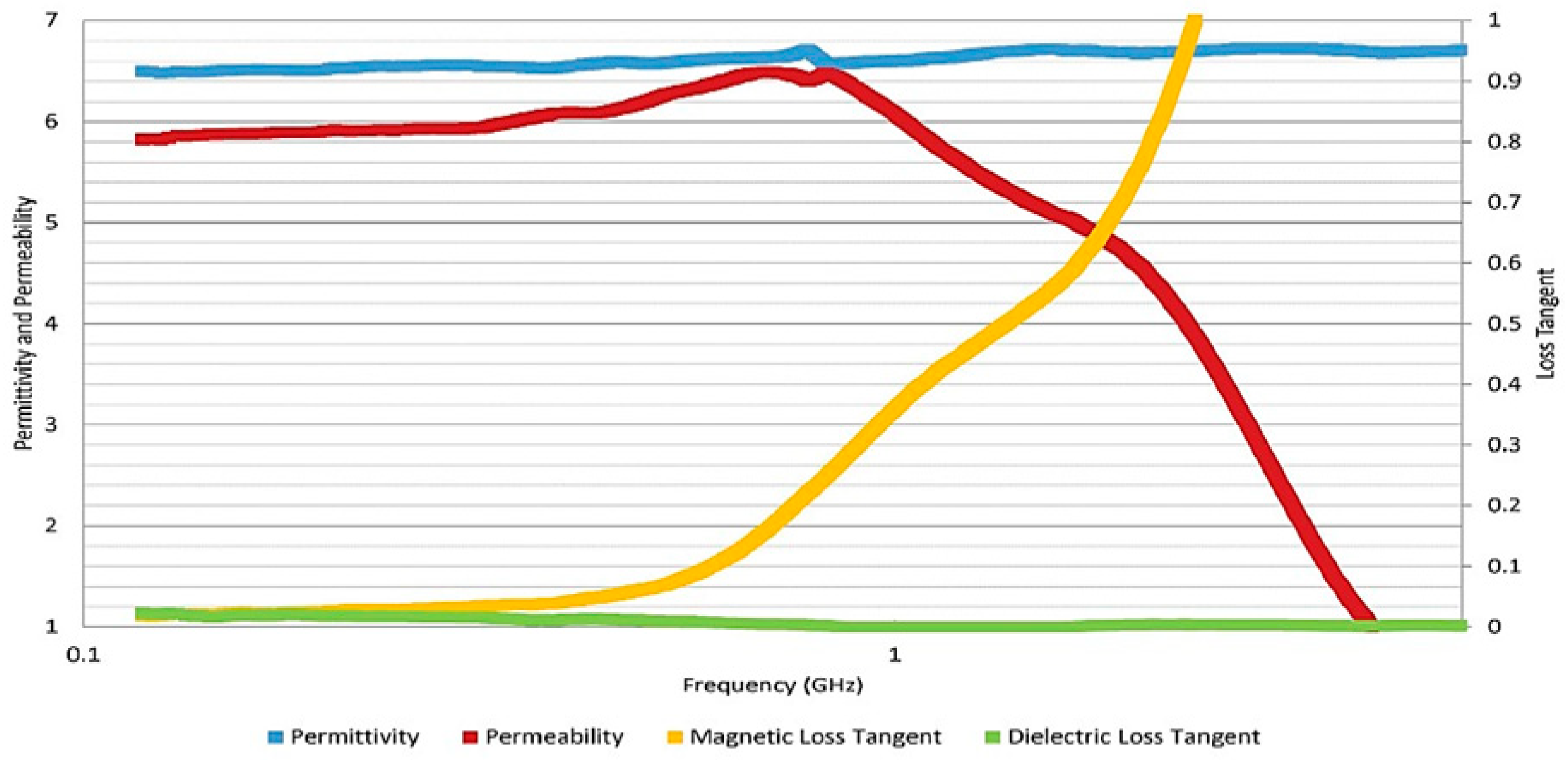
2. Magneto-Dielectric Material (MDM) Properties

The MDM used is MAGTREX™ 555 [19] substrate with 2 mm thickness. In Figure 1, we show the variation of the relative permeability and permittivity and the dielectric and magnetic loss tangent with a frequency range of 10 MHz to 2 GHz. We note that εr is constant and equal to 6.5, whereas μr remains constant up to 600 MHz, having a value of 6, then increases slightly up to a value of 6.5 at 700 MHz and finally decreases. A much lower value of dielectric loss tangent under 10−2 is observed. The value of the magnetic loss tangent remains low at 0.05 up to 400 MHz and then increases to be greater than 0.1 for f = 600 MHz. Hence, an antenna with a base MDM loading can be used in any frequency band from 10 MHz to 400 MHz and will have same factor of reduction in comparison to pure dielectric substrate material.

3. Planar Monopole Antenna Loaded with MDM

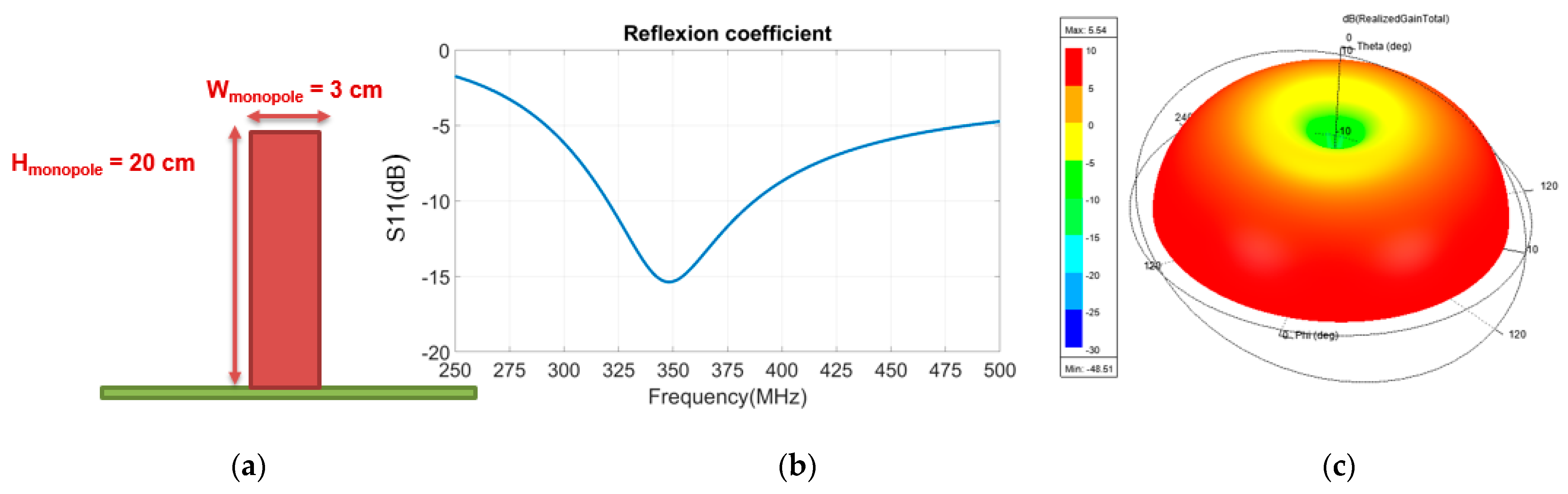
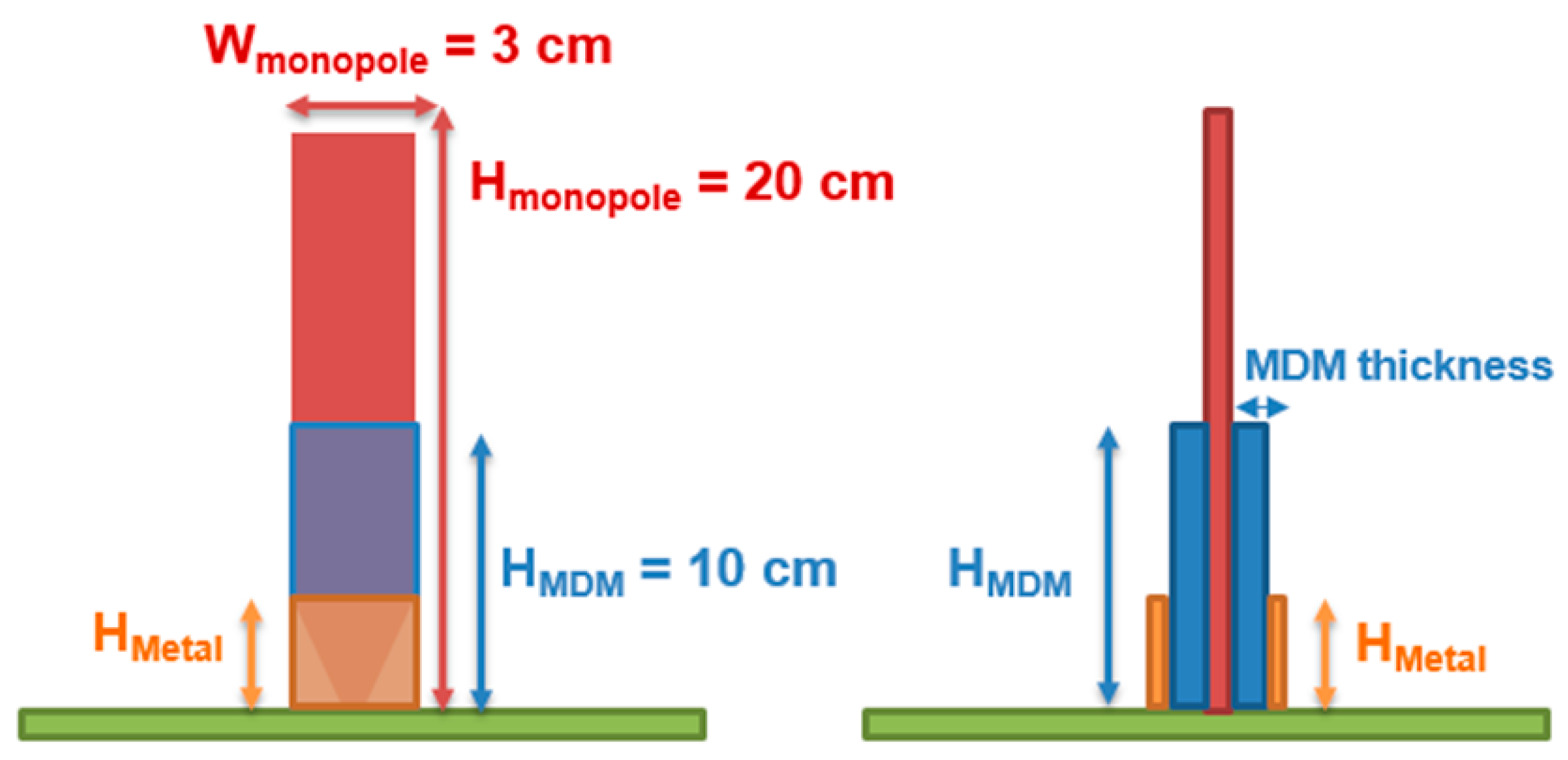
3.1. Specifications and Goal

In this paper, a magneto-dielectric material will be used in order to shift the resonance frequency of a 20 cm height, 3 cm width, and 1 mm thick antenna (Figure 2a) from 350 MHz (Figure 2b) to 200 MHz. During this study, the omnidirectional radiation pattern of the antenna has to be kept (Figure 2c). The realized gain value will be maximized. The main goal is to maximize this ratio and keep the antenna’s properties reasonable (bandwidth, gain, efficiency, and matching). All the results presented before the section «Antenna prototype realization» are EM simulations done with HFSS (High Frequency Structure Simulator) Software.

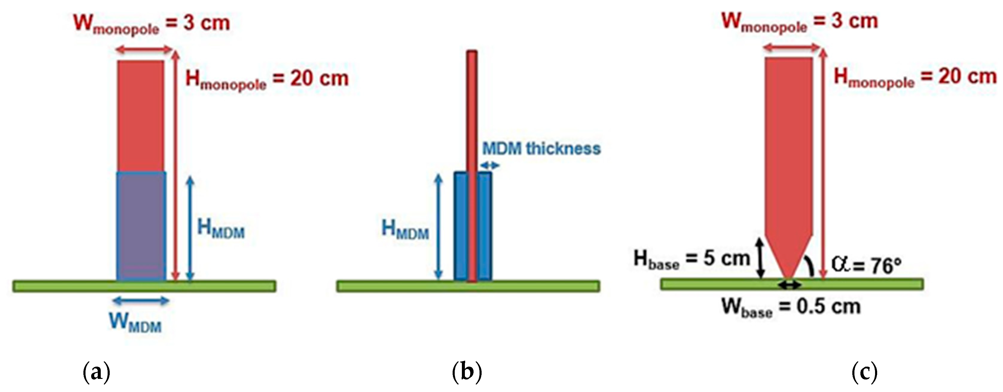
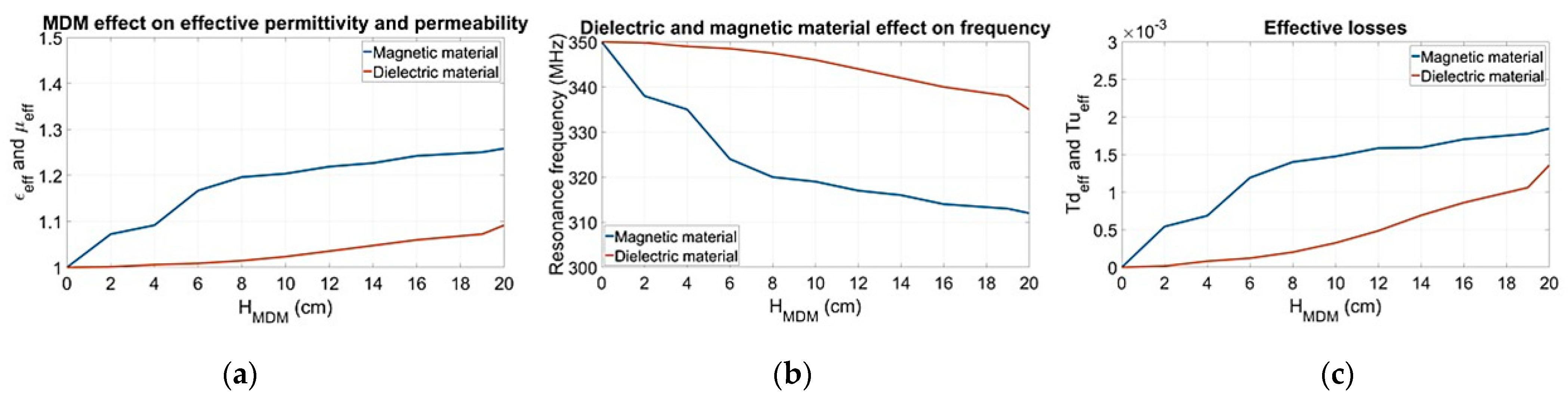
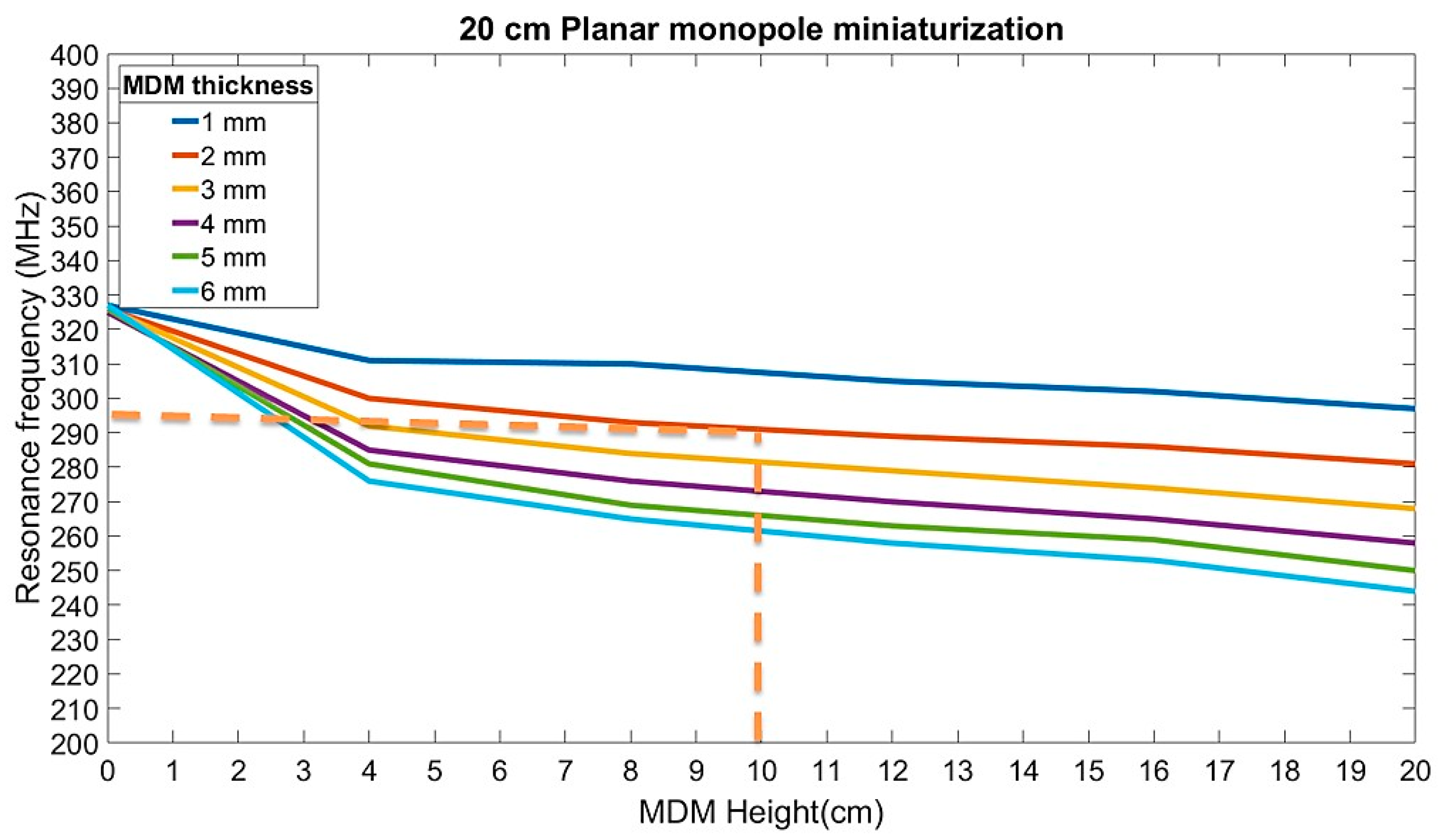
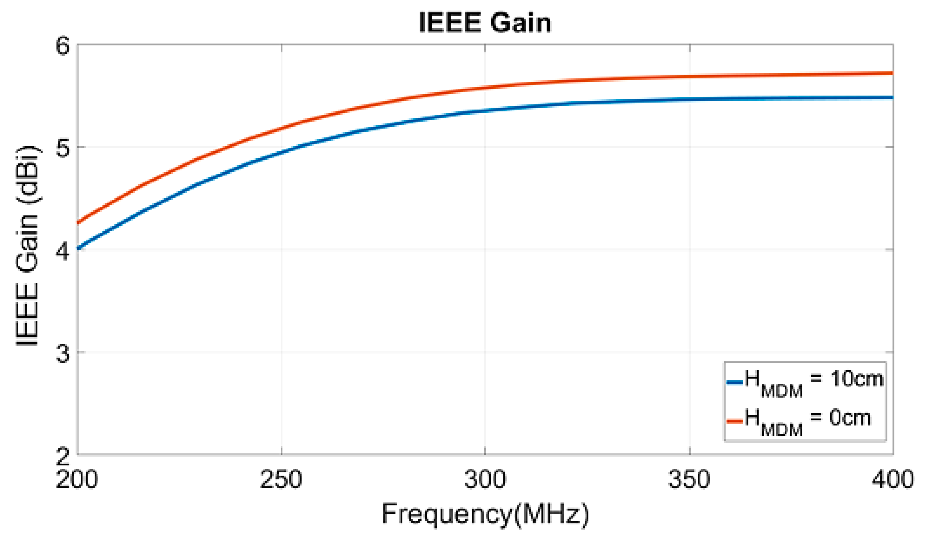
3.2. Impact of the MDM on Planar Monopole Antenna

We have previously shown that placing the MDM close to the source where the intensity of the magnetic field is the highest permits the obtention of an optimal miniaturization rate [13,14,15,16]. In this case, the effective permittivity is very low due to the very low electric field in this zone.
To illustrate these observations, MDM plates are placed on both sides of the antenna (see Figure 3). To demonstrate the effect of both properties, the antenna’s behavior with purely dielectric-material plates and magnetic-material plates is carried out. For the study, the plate’s dimensions are: thickness = 2 mm and width = 3 cm. The height varies from 0 cm (no material) to 20 cm (antenna height). The effective permittivity and permeability can be deduced by determining the shift of resonance frequencies obtained by the material using the following well-known expression [24]:
f 0 , M D M = f 0 , a i r ε e f f μ e f f = f 0 , a i r 1 μ e f f
With   ε e f f = 1 , μ e f f = ( f 0 , a i r f 0 , M D M ) 2 and   with   μ e f f = 1 , ε e f f = ( f 0 , a i r f 0 , M D M ) 2
f0,MDM is the antenna’s resonance frequency with MDM loading, f0,air the antenna’s resonance frequency in the air, and εeff and µeff are the effective permittivity and permeability. As expected, the effective permittivity is nearly one due to the very low electric field value in the loading zone, as shown in Figure 4b. The effective magnetic and dielectric losses (shown in Figure 4c) are determined by using the following equations [24,25]:
tan δ d , e f f = tan δ d 1 ε e f f 1 1 ε r 1
tan δ m , e f f = tan δ m 1 μ e f f 1 μ r
We can note that, when using 2 mm thickness of purely dielectric material (εr = 6.5; tandε = 0.01), its permittivity does not impact the antenna’s resonance frequency unless the material covers all the antenna’s height (Figure 4a), while resonance frequency shifting starts to be significant when a purely magnetic material (µr = 6; tandμ = 0.05) is placed in the lower half of the antenna’s height. With purely dielectric material covering only 10 cm of the monopole antenna, the maximum size reduction obtained will be around 1%, while it will be 8.5% with the magnetic material. So we can obtain almost the maximum miniaturization rate (11%) without covering all of the antenna’s structure. The effective permeability is more than 1.2 at HMDM = 10 cm, whereas the effective permittivity is nearly 1. The impact of the material’s relative permittivity is negligible. In this paper, we firstly optimized the permeability effect by loading the antenna’s base. The permittivity will be used later by adding metal parasitic plates. The second observation is that in order to reduce the material proportions, the material plates have to be placed in the high-current zone to obtain a better miniaturization rate.
The effective losses are shown in Figure 4c. It appears that the magnetic losses are higher than the dielectric ones due to the fact that μeff >> εeff. These losses are still very low <0.002.

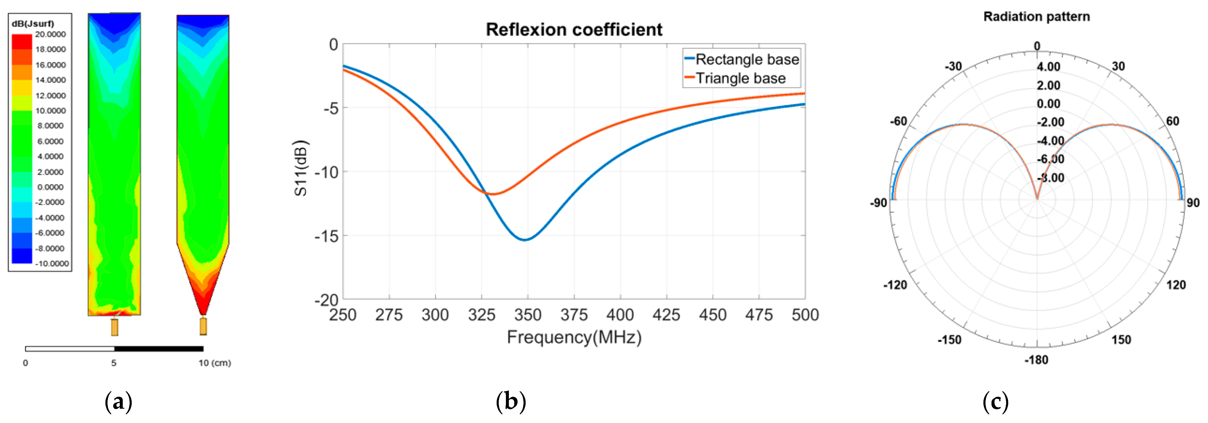
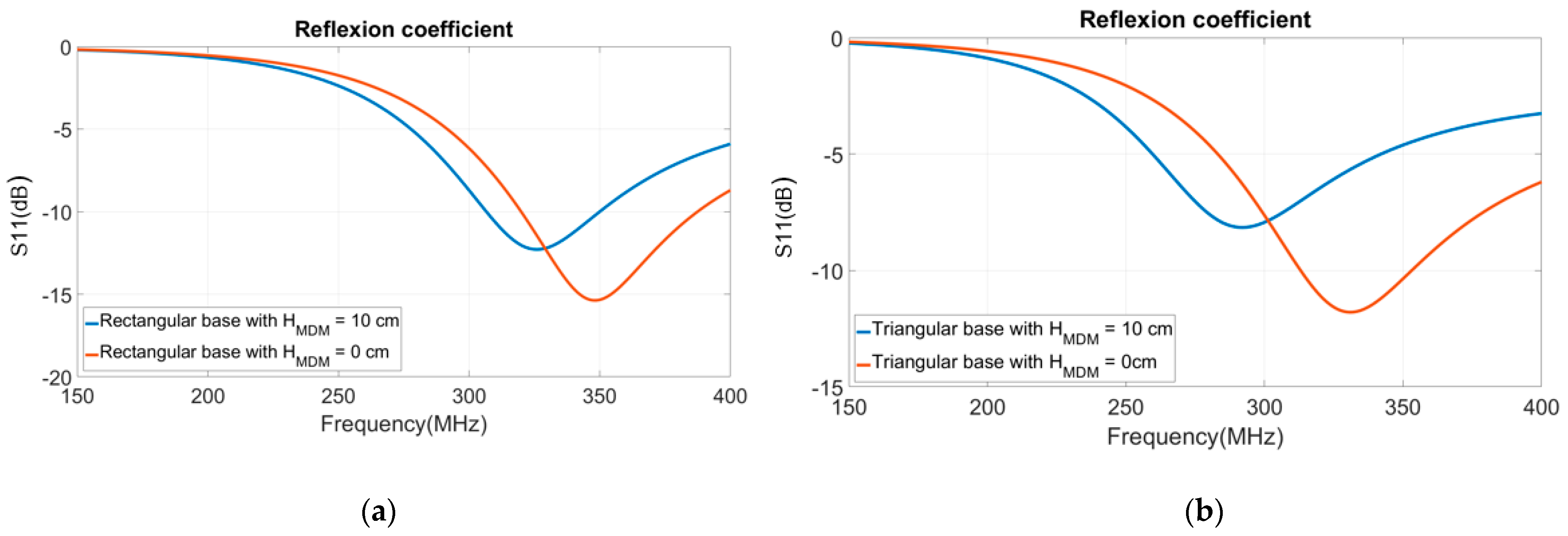
3.3. Modifying the Antenna Shape in Order to Increase the Permeability Effect

In order to optimize the magnetic effect to achieve a better miniaturization rate, it is proposed to reshape the antenna’s base to maximize the current and improve the effect on the effective permeability. Modifying the antenna’s base from a rectangle to a triangle (Figure 3c) increases the resonant length of the antenna that leads to a first frequency shift from 350 MHz to 330 MHz (Figure 5b). We can note that the surface current value increases in the triangular antenna base (see Figure 5a). The radiation pattern and gain is unchanged. (See Figure 5c).
MDM plates are added on both sides of the rectangle’s and the triangle’s antenna bases. These plates are 10 cm height, 3 cm width, and 2 mm thickness.
For the rectangular base, the frequency is shifted from 350 MHz to 318 MHz, corresponding to a 9% miniaturization rate (Figure 6a), and for the triangular one, the frequency is shifted from 330 MHz to 290 MHz, which correspond to a 12% miniaturization rate (Figure 6b). The effective permeability increased by more than 11.8% in this case, from 1.16 to 1.30.
Figure 7 is a useful chart to predict the antenna’s resonance frequency that can be obtained with different material dimensions. As shown in this figure, it is not possible to achieve a 200 MHz resonance frequency with reasonable material’s dimensions. Thus, it is proposed to use two MDM plates with the following dimensions: thickness = 0.2 cm, height = 10 cm, width = 3 cm.
Figure 8 represents the IEEE gain, which is the gain without the matching losses. The antenna loading with MDM reduces the antenna IEEE gain of 0.3 dB, which is negligible due to the small MDM losses, as shown in Figure 8. The antenna gain is still over 5 dB for a 17% miniaturized antenna.

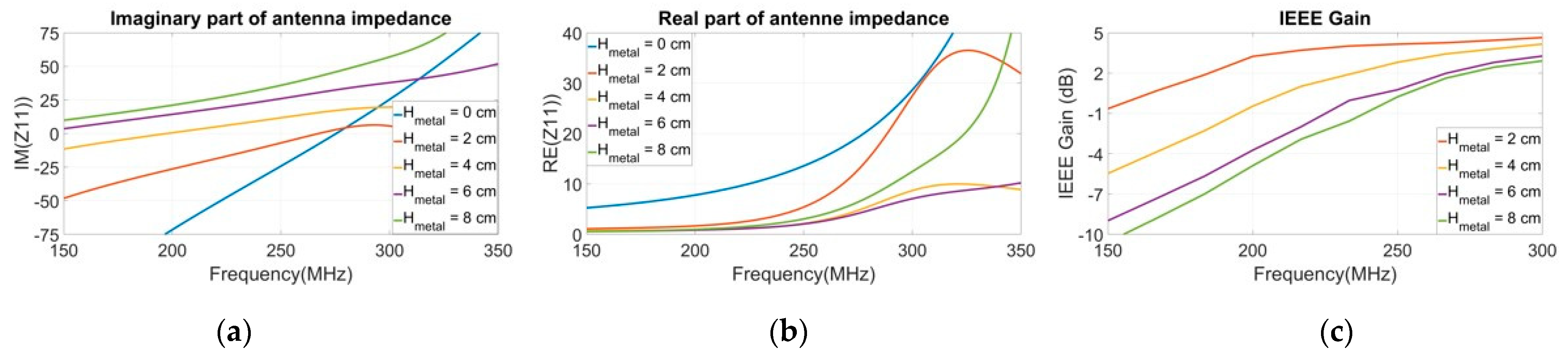
3.4. Adding Metallic Plates in Order to Optimize the Permittivity Effect

Attempting a very high miniaturization rate by shifting the frequency from 350 MHz to 200 MHz with MDM loading would lead to very high material volume (see Figure 7). To optimize the use of MDM, surrounding the material with a metallic sleeve causes a capacitive effect due to the material’s dielectric constant. With this capacitive effect, the antenna miniaturization rate can be significantly improved. The metal parasitic plates have to be placed on the antenna base on both sides of the MDM plates and connected to the ground plane in order to make two parallel capacitances useful in reducing the resonance frequency. The topology is shown in Figure 9.
A parametric study is carried out by changing the metal plates’ height from 0 cm (no metal plates) to 8 cm. The resonance frequency is shifted from 290 MHz (without metallic plate) to lower frequencies (See Figure 10a). The yellow curve (Hmetal = 4 cm) gives a resonant frequency of 200 MHz (aimed frequency). As shown in Figure 10c, adding metallic plates reduces the antenna IEEE gain. For Hmetal = 4 cm, the IEEE gain obtained in the desired frequency band is about −1.5 dBi, which is reasonable for such electrically small antennas (ka = 0.84 < 1 [21]). The parasitic metal plates do not change the radiation patterns shape (Figure 11) but reduce the gain according to Figure 10c.

4. Matching Network and Antenna Prototype Design

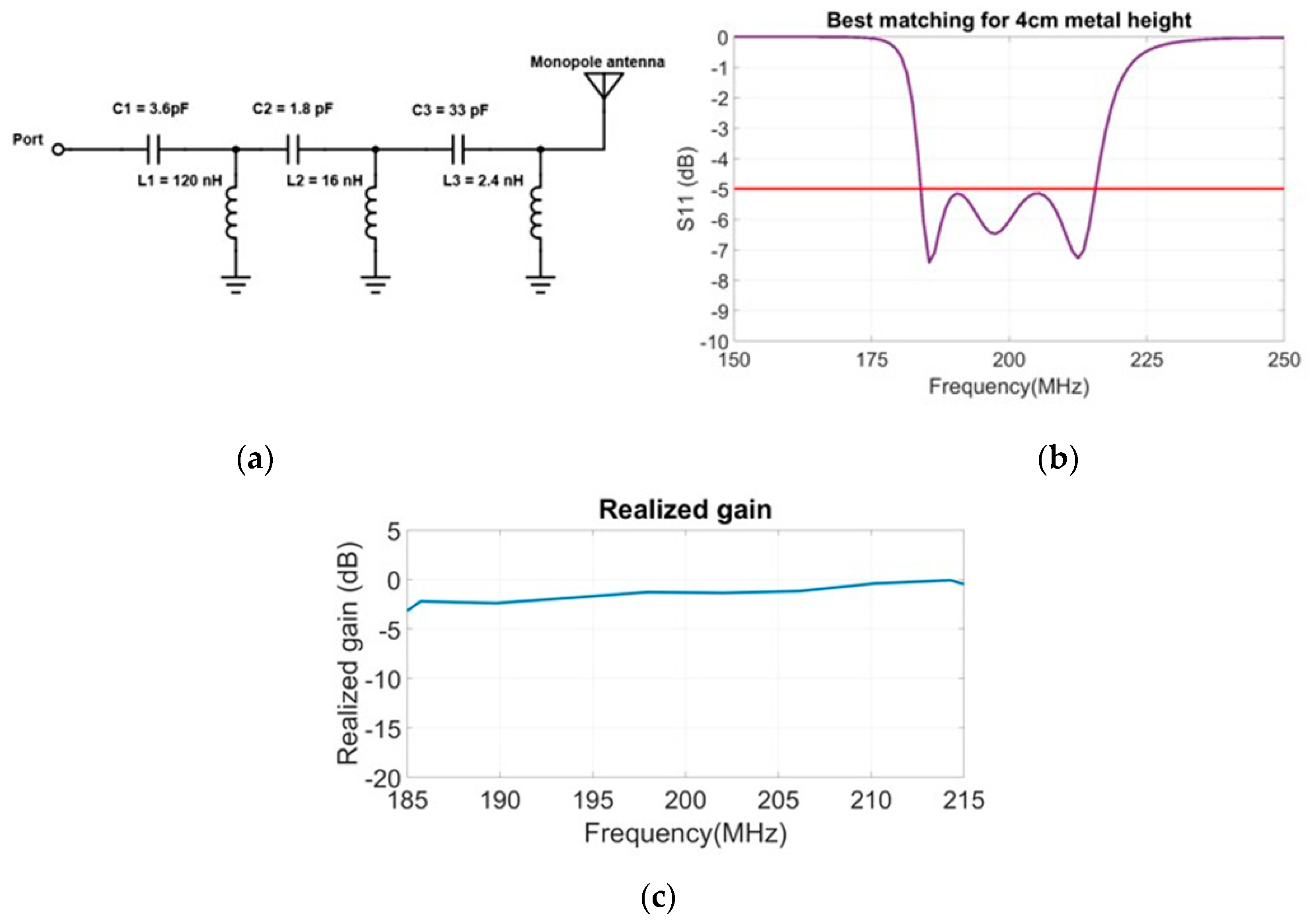
4.1. Matching Network Design with Real Frequency Technic (RFT)

Due to the antenna’s impedance modifications by adding parasitic metal plates, the antenna’s reflection coefficient has to be improved in order to make the antenna work in the aimed bandwidth. The matching circuit is optimized to match the antenna in the [185–215] MHz bandwidth at −5 dB according to the aimed application. To design such a matching circuit, optimization is performed with OptenniLab software. This software allows the use of all of the available circuit topologies (series and parallel) with capacitance and inductance. It is possible to optimize it in order to obtain the maximum available bandwidth and keep good circuit efficiency. In our case, to limit the circuit complexity, the component number is limited to six to avoid as much as possible the effect of the component tolerances. In an ideal case, it would have been possible to increase the bandwidth by adding more components (a maximum of ten components available in the software). This software uses the real frequency technic that is a powerful technic that optimizes the antenna matching using the simulated or measured antenna’s impedance matrix. [20,26] In this case, the simulated antenna’s impedance matrix has been used to design the matching network (see Figure 12a).
A good match at −5 dB is obtained over the required frequency band (see Figure 12b). Due to the matching network’s efficiency optimization made by OptenniLab, the realized gain in the maximum radiated power direction is remaining over −2 dB, which is remarkable for this electrically small antenna (see Figure 12c) [13,14,15,16]. The matching circuit has been designed with CMS components in order to be plugged between the VNA and the antenna prototype for the antenna impedance measurements (see Figure 13b).

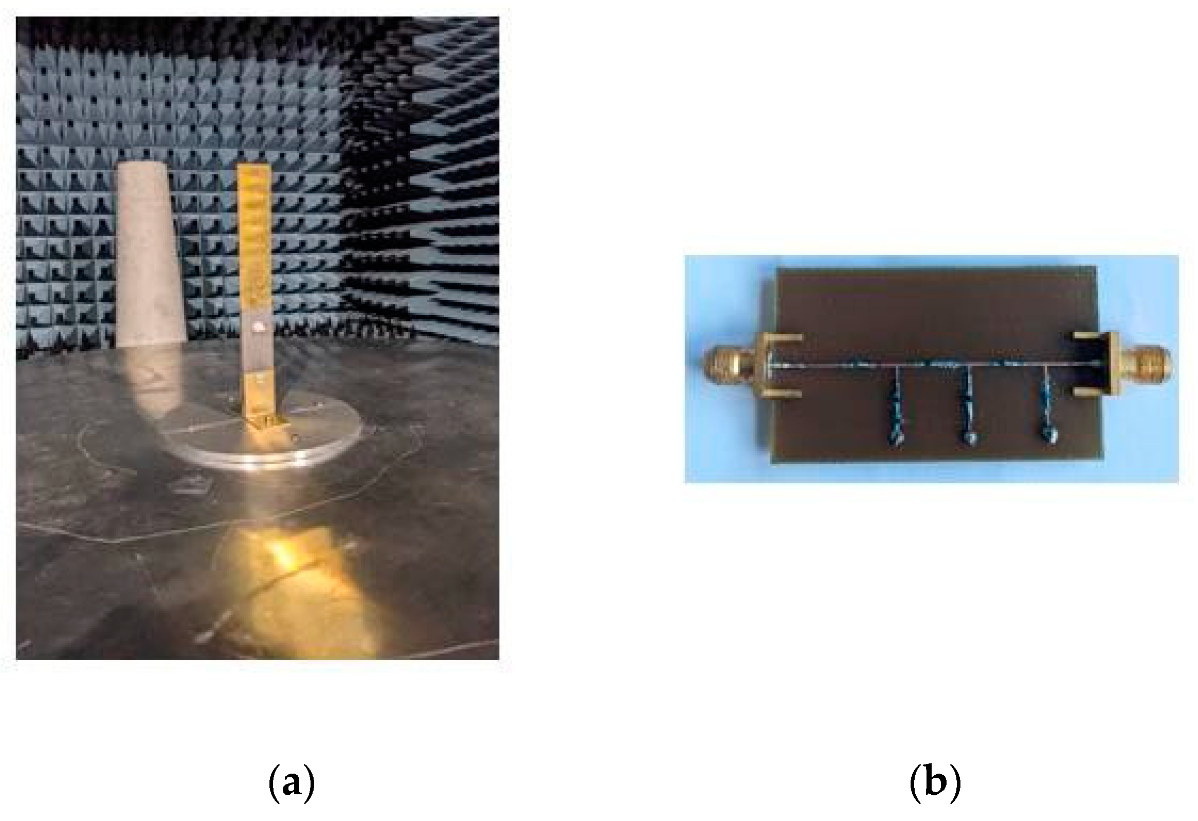
4.2. Antenna Prototype Realisation

To validate these results, an antenna prototype has been designed to match as much as possible the good simulation results. To design this prototype, the radiating element has been designed with brass cut by the water-jet method that permits the obtention of good cutting precision. This radiating element has been soldered with a coaxial feed placed at the center of a 1 m-diameter ground plane wide enough to obtain the right monopole behavior. Reducing this ground-plane size could lead to an antenna’s gain reduction and a radiation pattern’s shape modification. The 2 mm thick, 3 cm width, and 10 cm height MAGTREX™ 555 material has been cut and drilled in order to be fixed on the antenna radiating element with nylon screws. Finally, the square metallic plates have been designed with brass material in order to fix the bottom part over the ground plane and the top part on both sides of the material plates. (Figure 13a).

5. Results

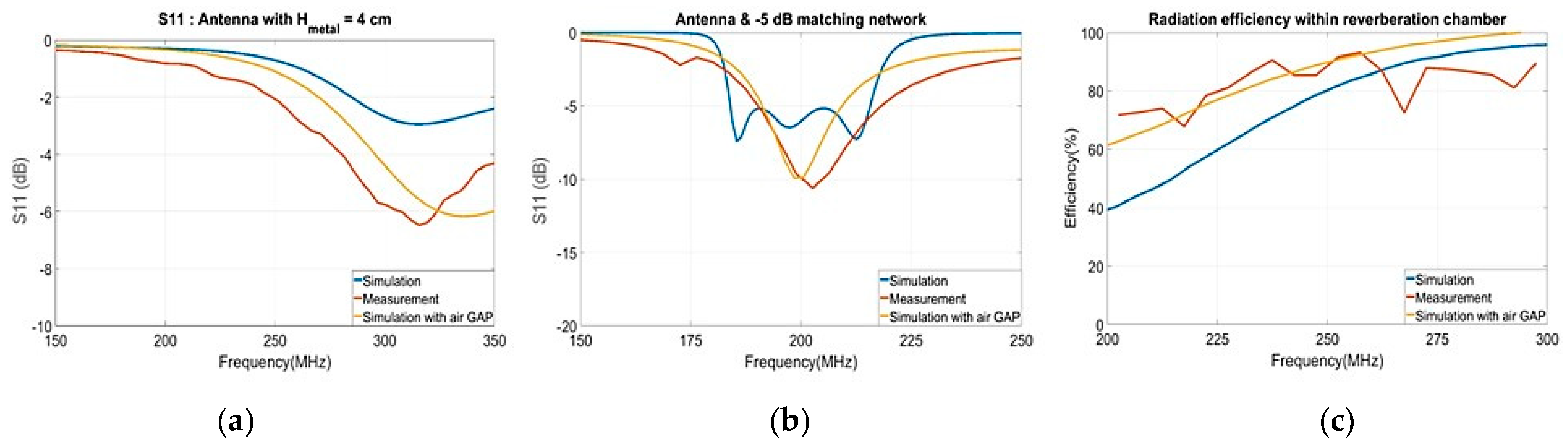
5.1. Impedance Measurements

The antenna prototype was measured in an anechoic chamber. First, as shown in Figure 14a, the antenna impedance is measured without the matching circuit. The measurement are in good agreement with the simulation. The antenna appears to be better-matched than the simulation, due to a 0.2 mm air gap located between the material and the metallic plates in the antenna prototype design. The antenna + matching network reflection coefficient (Figure 14b) is different than the simulation but is still in good agreement. The obtained antenna’s bandwidth is [190–220] MHz, which is the simulated bandwidth shift of 5 MHz to higher frequencies. In order to take account of the air-gap effect, it would have been better to design the antenna matching circuit by using the measured antenna’s impedance matrix.

5.2. Antenna Efficiency Measurement

Finally, a radiation efficiency measurement has been done in reverberation chamber [27] without the matching circuit and in the 200–300 MHz frequency band that is the lower frequency band available for this kind of measurements in this reverberation chamber. (See Figure 14c) These measurements are made in order to compare the simulated (blue curves) and measured (orange curves) antenna’s behavior. The yellow curves show the antenna’s properties simulated with the air gap. The orange curve shows a better radiated efficiency than the simulated one. To explain the increasing of the radiation efficiency, a simulation is made with a 0.2 mm air gap between the material and the metallic plates. It shows an increasing of the antenna’s radiation efficiency that fits with the measurements. This air-gap effect will be studied for future work in order to prove if it is worth it to voluntarily keep or suppress it. In this case, the effect only causes a small frequency shifting of the antenna bandwidth (5 MHz).

6. Discussion

In this paper, a new planar monopole miniaturization working in the VHF frequency band has been realized using a commercial laminate magneto-dielectric material. The magnetic properties of this material makes it useful for UHF and VHF antenna miniaturization. In order to use both the permeability and permittivity to achieve a size reduction of 43% a study has been carried out by first optimizing the antenna’s loading to use the material’s relative permeability in order to obtain a good miniaturization rate (17%). The originality in this work was to combine the MDM with metallic parasitic plates placed on both sides of the material plates to reduce the antenna’s resonance frequency. By adding a simple matching network, the antenna exhibits a bandwidth of 15% for a return loss of −5 dB. The maximum realized gain is over −2 dBi and the efficiency over 70%.

Author Contributions

Supervision, A.S.; Writing—original draft, T.F., A.S., A.-C.T., P.P. (Phillipe Pouliguen), P.P. (Patrick Potier), C.L.M. All authors have read and agreed to the published version of the manuscript.

Funding

This work was carried out in the framework of a PhD financed by the French innovation and defense agency and Thales six GTS.

Acknowledgments

These experiments have been possible with the precious Christophe Guitton’s work who realized the antenna prototype and Gilles Picoult’s expertise who realized the antenna’s matching circuit.

Conflicts of Interest

The authors declare no conflict of interest.

References

  1. Hansen, R.C.; Burke, M. Antennas with magneto-dielectrics. Microw. Opt. Technol. Lett. 2000, 26, 75–78. [Google Scholar] [CrossRef]
  2. Farzami, F.; Forooraghi, K.; Norooziarab, M. Miniaturization of a Microstrip Antenna Using a Compact and Thin Magneto-Dielectric Substrate. IEEE Antennas Wirel. Propag. Lett. 2011, 10, 1540–1542. [Google Scholar] [CrossRef]
  3. Mosallaei, H.; Sarabandi, K. Magneto-Dielectrics in Electromagnetics: Concept and Applications. IEEE Trans. Antennas Propag. 2004, 52, 1558–1567. [Google Scholar] [CrossRef] [Green Version]
  4. Li, Y.; Feng, Q. A Compact UHF Planar Monopole Antenna Using Magnetodielectric Ferrite Substrate. In Proceedings of the 2019 PhotonIcs & Electromagnetics Research Symposium—Spring (PIERS-Spring), Rome, Italy, 17–20 June 2019; pp. 2058–2061. [Google Scholar] [CrossRef]
  5. Zheng, Z.; Wu, X. A Miniaturized UHF Vivaldi Antenna With Tailored Radiation Performance Based on Magneto-Dielectric Ferrite Materials. IEEE Trans. Magn. 2020, 56, 1–5. [Google Scholar] [CrossRef]
  6. Pinsakul, A.; Promwong, S. Artificial Magneto-Dielectric Metamaterial with Microstrip Antenna for Wireless Applications. In Proceedings of the 2019 5th International Conference on Engineering, Applied Sciences and Technology (ICEAST), Luang Prabang, Laos, 2–5 July 2019; pp. 1–4. [Google Scholar] [CrossRef]
  7. Zheng, Z.; Yin, P.; Feng, Q. Low-Profile and Broadband Ferrite-Loaded Antenna for VHF/UHF Applications. In Proceedings of the 2021 International Applied Computational Electromagnetics Society (ACES-China) Symposium, Chengdu, China, 28–31 July 2021; pp. 1–2. [Google Scholar] [CrossRef]
  8. Jain, P.; Bansal, S.; Kumar, N.; Kumar, S.; Gupta, N.; Singh, A.K. Magneto-dielectric properties of composite ferrite based substrate for UHF band microstrip antenna. In Proceedings of the 2017 Progress in Electromagnetics Research Symposium—Spring (PIERS), St. Petersburg, Russia, 22–25 May 2017; pp. 981–983. [Google Scholar] [CrossRef]
  9. Adhiyoga, Y.G.; Rahman, S.F.; Apriono, C.; Rahardjo, E.T. Miniaturized 5G Antenna with Enhanced Gain by Using Stacked Structure of Split-Ring Resonator Array and Magneto-Dielectric Composite Material. IEEE Access 2022, 10, 35876–35887. [Google Scholar] [CrossRef]
  10. Sorocki, J.; Piekarz, I.; Slomian, I.; Gruszczynski, S.; Wincza, K. Realization of Compact Patch Antennas on Magneto-Dielectric Substrate Using 3D Printing Technology with Iron-Enhanced PLA Filament. In Proceedings of the 2018 International Conference on Electromagnetics in Advanced Applications (ICEAA), Cartagena De Indias, Colombia, 10–14 September 2018; pp. 185–188. [Google Scholar] [CrossRef]
  11. Chzhan, A.V.; Podorozhnyak, S.A.; Zharkov, S.M.; Gromilov, S.A.; Patrin, G.S. Induced magnetic anisotropy of Co-P thin, films obtained by electroless deposition. J. Magn. Magn. Mater. 2021, 537, 168129. [Google Scholar] [CrossRef]
  12. Xu, Z.; Cui, J.; Zhang, C.; He, D.; Wang, T. High-frequency magnetic properties and micro-magnetic structure of Co2W-type ferrite with Bi2O3 addition for potential antenna applications. J. Magn. Magn. Mater. 2022, 562, 169815. [Google Scholar] [CrossRef]
  13. Kabalan, A.; Sharaiha, A.; Tarot, A.-C. Electrically Small Wideband Monopole Antenna Partially Loaded with Low Loss Magneto-Dielectric Material. Magnetism 2022, 2, 17. [Google Scholar] [CrossRef]
  14. Finet, T.; Sharaiha, A.; Tarot, A.-C.; Pouliguen, P.; Potier, P. Low profile folded monopole antenna higly miniaturized by the use of low loss magnetodielectic materials in the VHF frequency band. In Proceedings of the 2021 IEEE Conference on Antenna Measurements & Applications (CAMA), Antibes Juan-les-Pins, France, 15–17 November 2021; pp. 202–203. [Google Scholar] [CrossRef]
  15. Batel, L.; Delaveaud, C.; Pintos, J.-F. Miniaturization of a Monopolar Wire-Plate Antenna Using Magneto-Dielectric Material. In Proceedings of the 2019 International Workshop on Antenna Technology (iWAT), Miami, FL, USA, 3–6 March 2019; pp. 91–94. [Google Scholar] [CrossRef]
  16. Vassallo, F.A.; Duncan, K.J.; Boylston, O.; Kratch, A.; Bennett, D.T.; Correa, J.C. UHF SATCOM antenna ground plane height reduction using Ni-Zn magneto-dielectric materials. In Proceedings of the 2016 USNC-URSI Radio Science Meeting, Fajardo, PR, USA, 26 June 2016–1 July 2016; pp. 93–94. [Google Scholar] [CrossRef]
  17. Mattei, J.-L.; Huitema, L.; Queffelec, P.; Pintos, J.; Minard, P.; Sharahia, A.; Jamnier, B.; Ferrero, F.; Staraj, R.; Souriou, D.; et al. Suitability of Ni-Zn Ferrites Ceramics with Controlled Porosity as Granular Substrates for Mobile Handset Miniaturized Antennas. IEEE Trans. Magn. 2011, 47, 3720–3723. [Google Scholar] [CrossRef]
  18. Mattei, J.-L.; le Guen, E.; Chevalier, A. Dense and half-dense NiZnCo ferrite ceramics: Their respective relevance for antenna downsizing, according to their dielectric and magnetic properties at microwave frequencies. J. Appl. Phys. 2015, 117, 084904. [Google Scholar] [CrossRef]
  19. MAGTREX 555. Available online: https://www.rogerscorp.com/advanced-electronics-solutions/magtrex-555-high-impedance-laminates (accessed on 5 October 2022).
  20. Ramahi, M.; Mittra, R. Design of a matching network for an HF antenna using the real frequency method. IEEE Trans. Antennas Propag. 1989, 37, 506–509. [Google Scholar] [CrossRef]
  21. Chu, L.J. Physical limitations of omni-directionalantennas. J. Appl. Phys. 1948, 19, 1163–1175. [Google Scholar] [CrossRef]
  22. Harrington, R.F. Effect of antenna size on gain, bandwidth, and efficiency. J. Res. Natl. Bur. Stand.-D Radio Propag. 1960, 64D, 1. [Google Scholar] [CrossRef]
  23. Best, S.R. A discussion on the quality factor of impedance matched electrically small wire antennas. IEEE Trans. Antennas Propag. 2005, 53, 502–508. [Google Scholar] [CrossRef]
  24. Rialet, D.; Sharaiha, A.; Tarot, A.-C.; Delaveaud, C. Estimation of the Effective Medium for Planar Microstrip Antennas on a Dielectric and Magnetic Truncated Substrate. IEEE Antennas Wirel. Propag. Lett. 2012, 11, 1410–1413. [Google Scholar] [CrossRef]
  25. Pucel, R.A.; Mass, D.J. Microstrip propagation on magnetic substrates—Part I: Design theory and part II: Experiment. IEEE Microw. Theory Technol. 1972, MTT-20, 304–308. [Google Scholar] [CrossRef]
  26. Carlin, H.; Yarman, B. The double matching problem: Analytic and real frequency solutions. IEEE Trans. Cir-Cuits Syst. 1983, 30, 15–28. [Google Scholar] [CrossRef]
  27. Krouka, W.; Sarrazin, F.; Sol, J.; Philippe, B.; Elodie, R. Biased Estimation of antenna Radiation Efficiency within Reverberation Chambers Due to Unstirred Field: Role of Antenna Stirring. IEEE Trans. Antennas Propag. 2022, 70, 9742–9751. [Google Scholar] [CrossRef]
Figure 1. MAGTREX™ 555 radioeletric properties.
Magnetism 02 00026 g001
Figure 2. (a) Planar monopole antenna geometry. (b) Reflection coefficient versus frequency. (c) 3D radiation pattern at 350 MHz.
Magnetism 02 00026 g002
Figure 3. (a) Loaded monopole antenna with MDM—front view, (b) side view, (c) triangle base antenna dimensions.
Magnetism 02 00026 g003
Figure 4. (a) Monopole antenna resonance frequency. (b) Effective permittivity and permeability. Effective losses tangent. (c) versus purely magnetic and dielectric material height.
Magnetism 02 00026 g004
Figure 5. (a) Surface current for rectangular and triangular monopole antenna bases, (b) reflection coefficient for rectangular and triangular antenna bases, (c) radiation pattern at 350 MHz (rectangle) and 330 MHz (triangle).
Magnetism 02 00026 g005
Figure 6. Reflection coefficient versus the frequency of a loaded monopole: (a) Rectangular base antenna, (b) triangular base antenna.
Magnetism 02 00026 g006
Figure 7. Resonance frequency evolution of the monopole antenna versus MDM height for different values of MDM thickness.
Magnetism 02 00026 g007
Figure 8. Monopole gain versus frequency with and without MDM loading.
Magnetism 02 00026 g008
Figure 9. Final antenna topology.
Magnetism 02 00026 g009
Figure 10. Effect of various metallic plates’ height on the antenna: (a) imaginary part of the impedance, (b) real part of the impedance, (c) IEEE gain.
Magnetism 02 00026 g010
Figure 11. Radiation pattern: (a) elevation plane, (b) azimuth plane.
Magnetism 02 00026 g011
Figure 12. Matching network for −5 dB matching: (a) designed circuit, (b) antenna + circuit S11, (c) antenna + circuit realized gain.
Magnetism 02 00026 g012
Figure 13. Reflection coefficient versus frequency of a loaded monopole: (a) rectangular base antenna, (b) triangular base antenna.
Magnetism 02 00026 g013
Figure 14. Simulated and measured final antenna: (a) Reflection coefficient without matching network, (b) reflection coefficient with the matching network, (c) radiation efficiency without matching network.
Magnetism 02 00026 g014
Publisher’s Note: MDPI stays neutral with regard to jurisdictional claims in published maps and institutional affiliations.

