Article

Development and Usability of a Prototype Upper Extremities Lever-Driven Exercise System

by
Themistoklis Tsatalas
1,2,*,
George Bellis
1,
Evangeli Karampina
1,3,
Charalampos Krommidas
2,
Fotios Tsilfoglou
4,
Athanasios Patas
4,
Christos Fotos
4,
Christos Kokkotis
1,3,
Athanasios Z. Jamurtas
2 and
Giannis Giakas
1,2
1
Biomechanical Solutions, 43100 Karditsa, Greece
2
Department of Physical Education and Sport Science, University of Thessaly, 42100 Trikala, Greece
3
Department of Physical Education and Sport Science, Democritus University of Thrace, 69100 Komotini, Greece
4
Polytech S.A., 41222 Larisa, Greece
*
Author to whom correspondence should be addressed.
BioMed 2023, 3(1), 32-49; https://doi.org/10.3390/biomed3010003
Submission received: 5 November 2022 / Revised: 23 December 2022 / Accepted: 23 December 2022 / Published: 27 December 2022

Abstract

:
The purpose of this paper is to present the design, construction, and technical aspects of a prototype upper extremities lever-driven exercise system, called FIT-WHEEL (Functional and Intelligent Training system for WHEELchair users), as well as the preliminary experimental measurements conducted to test the device’s usability in healthy individuals. FIT-WHEEL was developed to provide a training modality that combines the known benefits of eccentric exercise and lever-propelled wheelchairs. Eleven healthy male participants performed, seven days apart, a moderate intensity concentric and eccentric exercise protocol on FIT-WHEEL consisting of 30 trials of both upper extremities at 30% of peak concentric and peak eccentric force, respectively. At the end of each exercise bout, participants completed a number of valid and reliable instruments examining attitudes, intention and enjoyment during concentric or eccentric exercise on the FIT-WHEEL system as well as the usability of the two exercise protocols on the novel lever-driven exercise system. Statistical analyses revealed high scores in all the examined parameters (attitudes, intention, enjoyment, and usability) in both eccentric and concentric exercise protocols, without any significant differences emerging between them. Moreover, total mechanical work during eccentric exercise was 18.3% higher compared to concentric exercise performed on the FIT-WHEEL training system (p = 0.001). The preliminary experimental results discussed serve as an initial step to implement lever-driven eccentric exercise in wheelchair dependent populations in the future and evaluate the potential long-term benefits and limitations.

1. Introduction

It is widely recognized that physical activity enhances physical health and psychological well-being, promotes functional independence and social participation, decreases the risk of secondary health conditions, and consequently leads wheelchair users to improved quality of life [1,2,3]. This population group relies mainly on upper extremities to exercise and failing to do so results in progressive physical deconditioning, decreasing functional capacity as well as significant financial burden [1,4,5]. Despite the benefits, wheelchair users engage in limited physical activity and have lower physical fitness compared to the general population [1,4,6]. It has been reported that approximately 50% of patients with spinal-cord injury (SCI) that use wheelchairs do not exercise at all and 15% participate in physical activity below the threshold required to induce health benefits [4].
Several barriers are associated with physical activity adherence in wheelchair users, including lack of accessible facilities and adaptive exercise modalities, limited one-on-one support from health professionals due to high expenses, safety considerations, secondary health conditions and inability to tailor exercise to accommodate the individual needs and the varied levels of physical condition of wheelchair users [7,8,9]. With these concerns in mind, novel specialized exercise modalities easily accessible at home, in local rehabilitation centers and fitness facilities, may contribute to increased enjoyment and motivation to exercise in wheelchair users. Commercially available exercise options such as concentric arm crank ergometers [10,11], wheelchair ergometers [12,13,14], and adaptive rowing that incorporates functional electrical stimulation [10,15] fail to meet this need, given that they are either difficult to access in the community or are expensive.
The research group of Elmer et al. [16,17] developed a novel eccentric arm cycle ergometer that can be employed to perform eccentric exercise in the upper extremities with lower levels of cardiorespiratory demand and perceived exertion compared to standard concentric arm crank ergometers. Moreover, Elmer et al. found that seven weeks of eccentric arm cycling conducted at a moderate intensity increased upper extremity strength in a healthy cohort significantly more than concentric exercise [18] and recently implemented eccentric arm cycling safely and efficiently in manual wheelchair users [19]. These findings underline the prospect of taking advantage of the high-intensity and low-cost nature of eccentric exercise [20,21] as a training and rehabilitation method for wheelchair users. However, an important factor to consider during exercise in wheelchair users is not to exacerbate shoulder, elbow and wrist pain which stems from chronic overuse related to wheelchair propulsion [22]. Arm crank ergometry is conducted in front of the body and predominantly engages muscles of the anterior upper extremities [14]. Therefore, a safer and more functional eccentric exercise modality could be optimal to lessen strength imbalance between the anterior and posterior upper extremities muscles that progressively develops due to repetitive wheelchair propulsion.
A potential approach to eccentrically exercise the upper body could be based on a lever-driven training modality. Lever-propelled wheelchairs are commercially available and are more mechanically efficient and less straining for the joints compared to the standard manual wheelchairs [12]. The upper extremities follow a cyclic trajectory in the sagittal plane (single degree of freedom movement) at the ventral level [23]. Additionally, lever propulsion offers an improved force distribution between the anterior and the posterior musculature and a more natural positioning of the shoulder, arm and wrist compared to the crank-propelled and standard manual wheelchairs [12,23]. As a result, upper body pain and injuries are reduced [12].
The purpose of this paper is to present the design and technical aspects of a prototype upper body lever-driven exercise system, called FIT-WHEEL (Functional and Intelligent Training system for WHEELchair users), as well as the preliminary experimental measurements conducted to test the device’s usability in healthy individuals. FIT-WHEEL was developed to provide a training option which engages safely and efficiently both the anterior and posterior upper extremity muscles and combines the known benefits of eccentric exercise and lever propulsion to improve the strength and endurance capacity of wheelchair users. We hypothesized that no differences will be found in usability scores between the eccentric and concentric mode of exercise employed on the FIT-WHEEL training system in healthy individuals. However, considerably higher mechanical work was anticipated during the eccentric exercise protocol compared to the respective concentric protocol performed with equivalent intensity.

2. Materials and Methods

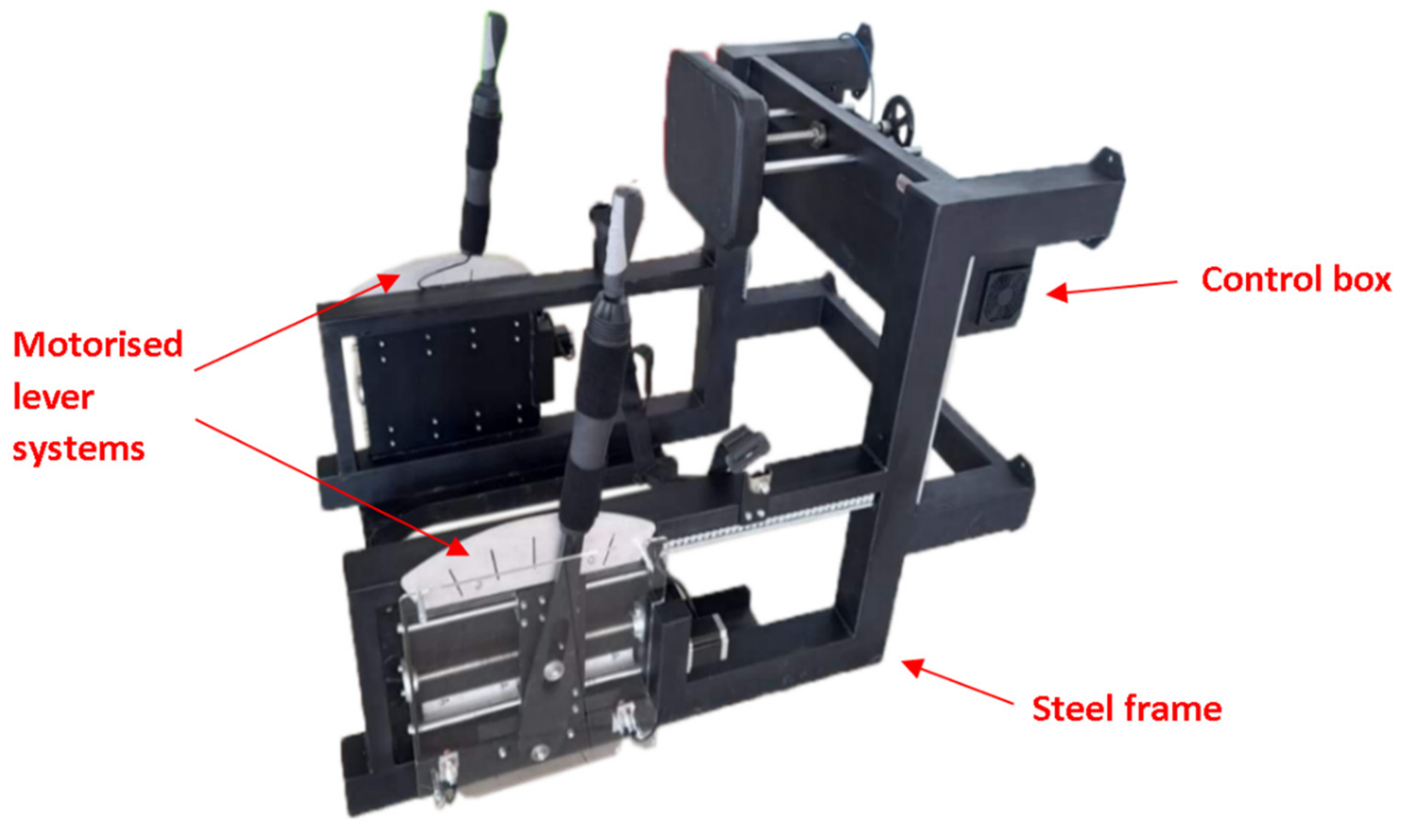
2.1. Device Overview

In this section, an overview of the essential components of the device is provided. As shown in Figure 1, FIT-WHEEL consists of a steel frame that is used as a “chassis” on which every other part is mounted on two motorised lever systems, one for each upper extremity that provide different training modes (eccentric, concentric or isometric exercise) to the user and the control box which contains the power supply, the motion control, data acquisition and connectivity systems.
In Figure 2, the front part of the device is presented. The empty space between the two levers is where the user accesses the device, by moving backwards, while being on the wheelchair. The existing rails on the bottom of the steel frame are designed to guide the wheelchair in proper place, approximately in the middle and secure it from side movements. For the suitable dimensioning of the rails and the steel frame, a variety of wheelchair dimensions available on the market were considered. As shown in Figure 2, the FIT-WHEEL design includes a two-point seat belt, which the user fastens and adjusts horizontally around the belly before exercising on the training device. The steel frame offers multiple spots where the two parts of the belt can be threaded, so that more than one belt can be used if necessary and secures the user in a stationary position.
In Figure 3a, the rear view of the device is depicted. The control box is mounted on the steel frame, behind the user. Additionally, on the back of the user, there is a position regulator. It includes a hard pillow, the position of which can be adjusted by turning the screw shaft. Proper linear regulation of the pillow is essential, so that the user’s upper extremities come to a safe and ergonomic range of motion during exercise (Figure 3b).
As a general description of the essential components of the device and their function is already provided, an overview on safety features is presented (Figure 4). The user is secured in a stationary position, as the belt is fastened around the belly restrains forward movement, the back leans against the position regulator and restrains backward movement and the wheelchair guiding rails in the bottom of the steel frame restrain lateral movement. The device does not displace during operation, as any reaction force produced is absorbed by the steel frame, causing only internal mechanical strain. The user’s extremities stay away from any steel frame surface that could cause injuries and any moving mechanical parts—except the lever grips—are kept away from user’s body.

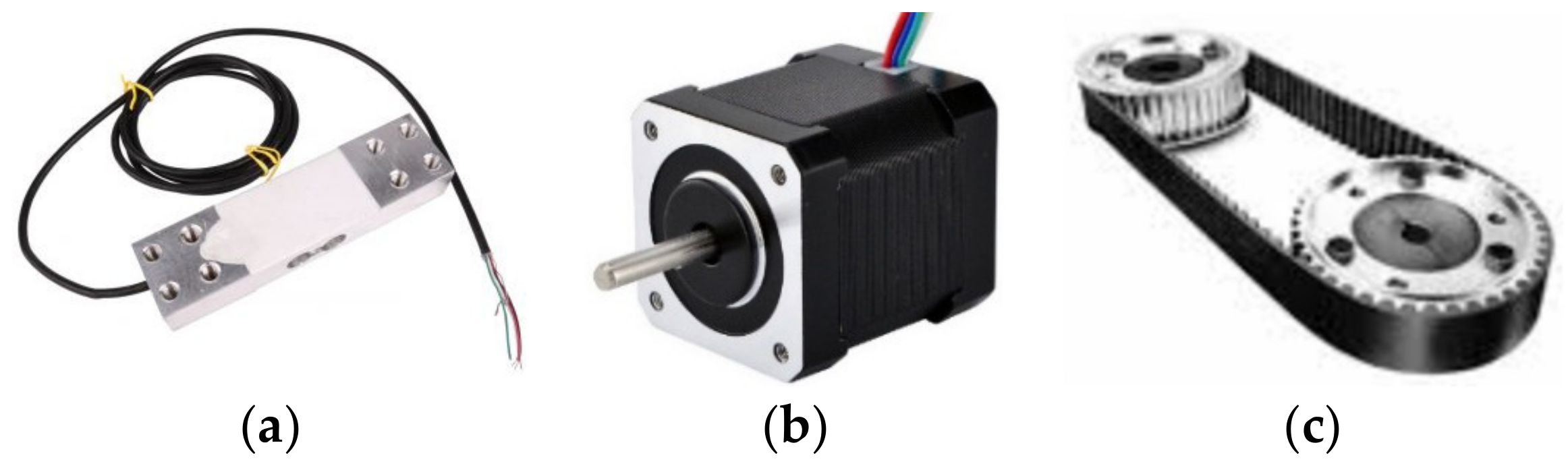
2.2. Technical Description of the Device Main Components

The following descriptions provide further information on the selected materials and parts as well as the design features, crucial parameters and constraints taken into account.

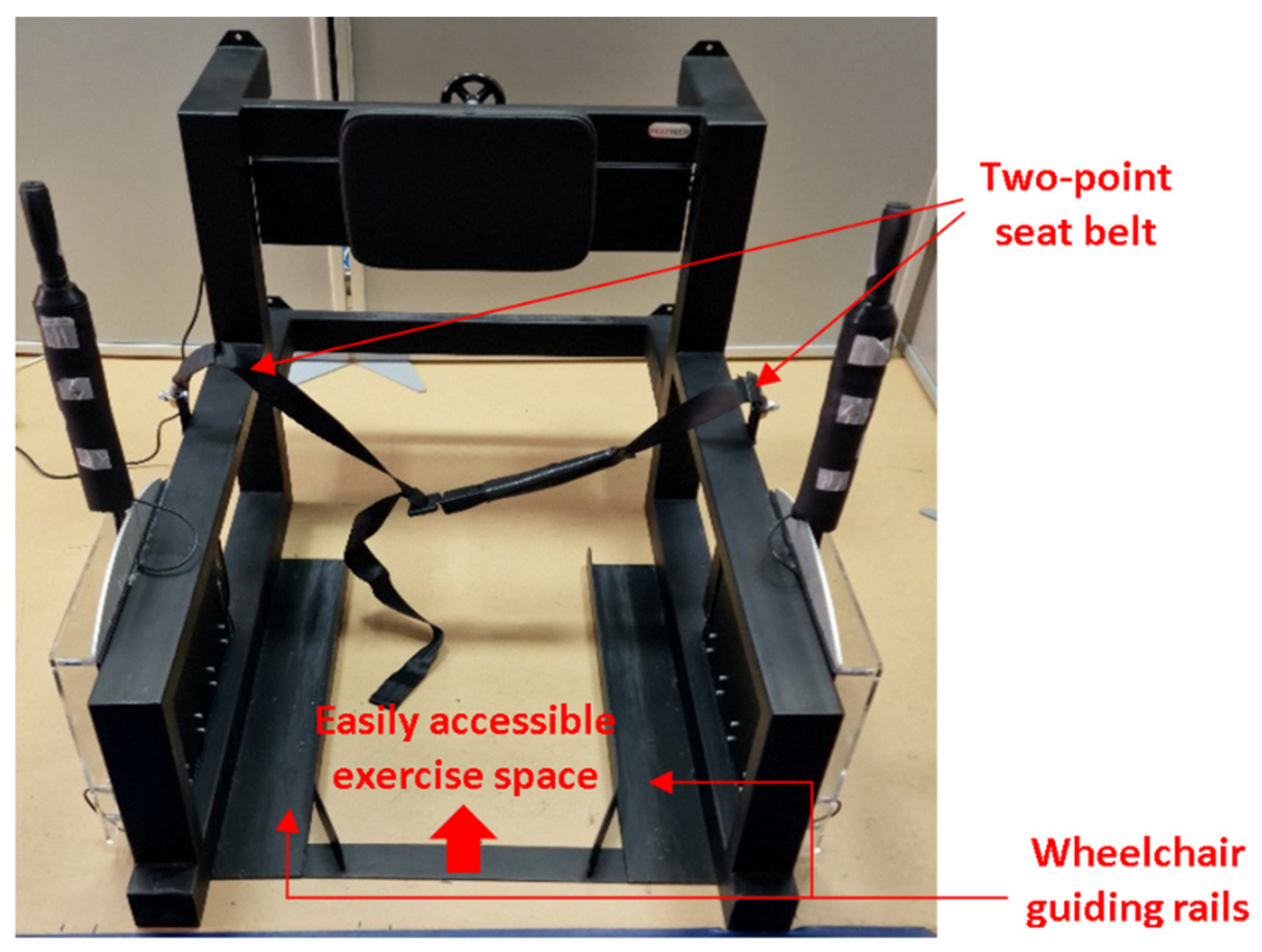
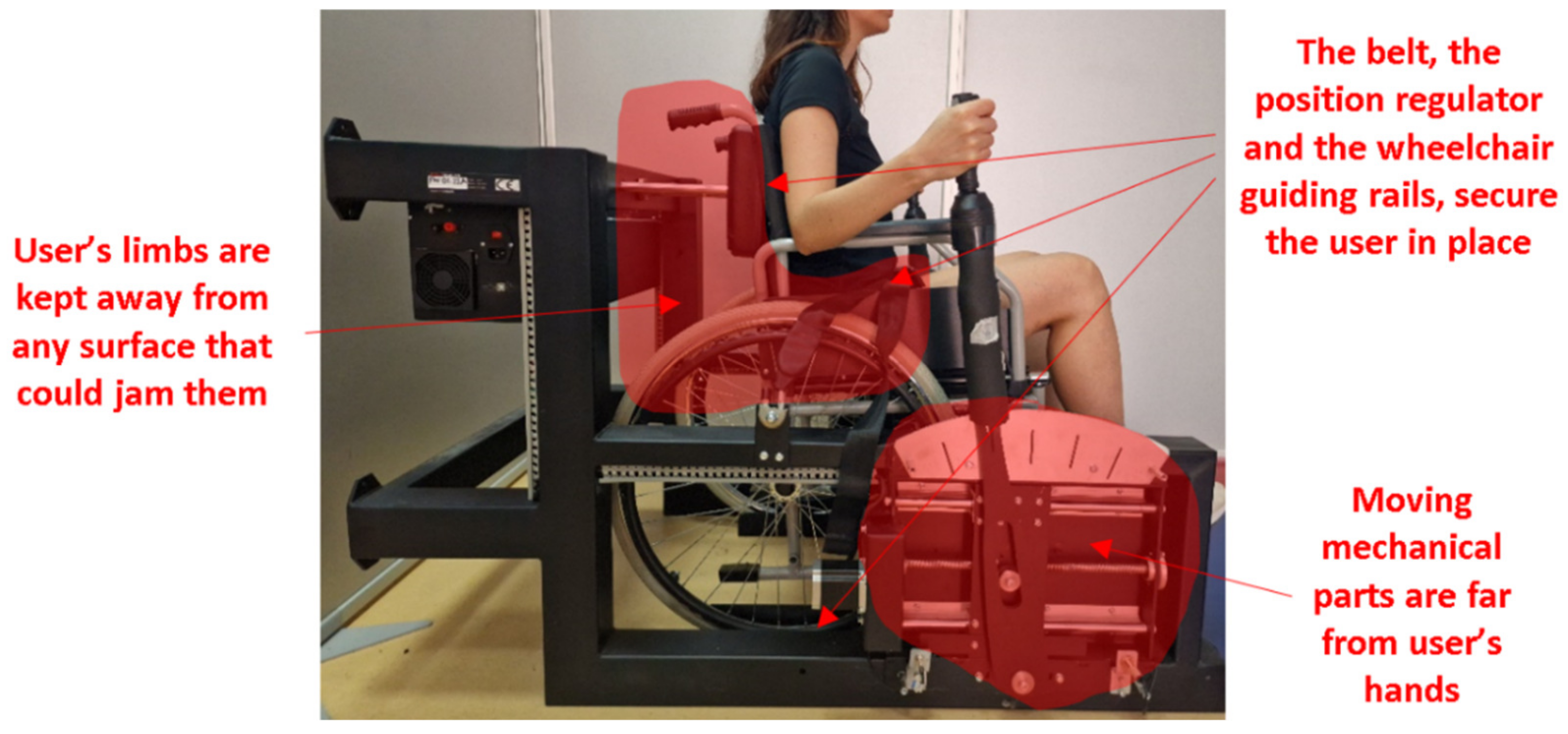
2.2.1. Technical Description of the Steel Frame

The basic structure on which every other part is mounted on is described as the steel frame (Figure 5). This steel structure is assembled with precision cut and welded hollow tubes. The design and dimensioning offer easy accessibility and safe and ergonomic operation for the end users. Other parameters that were considered for the design were the endurance to maximum estimated mechanical strain, the need for portability and the minimized weight. The wheelchair guiding rails in the bottom of the structure are fabricated from bended metal sheet, welded on the structure. On the rear side of the structure, wall mounting steel plates are welded, providing an option of mounting the device on the wall. The steel frame is electrostatically painted to avoid any rust appearance.

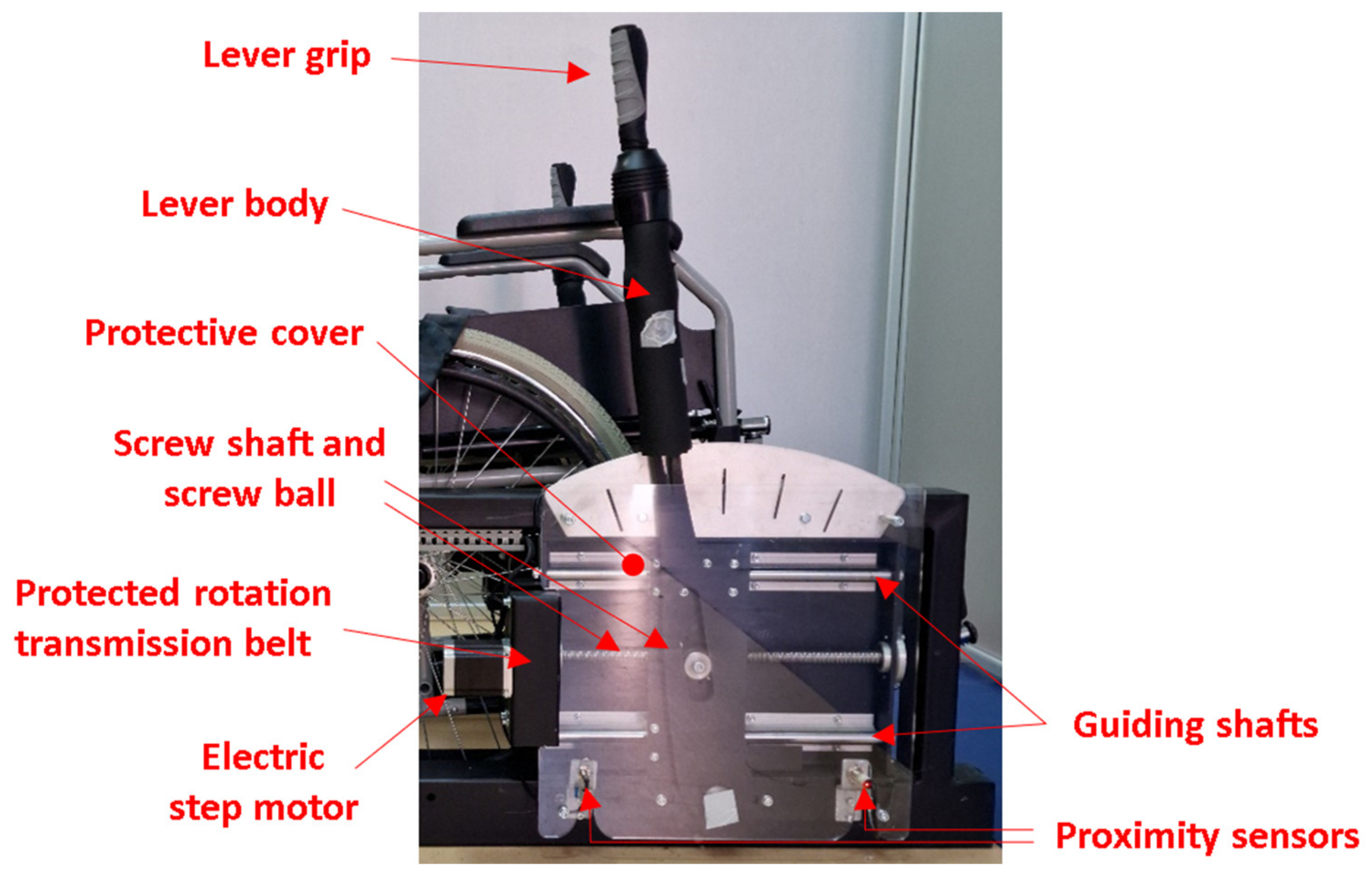
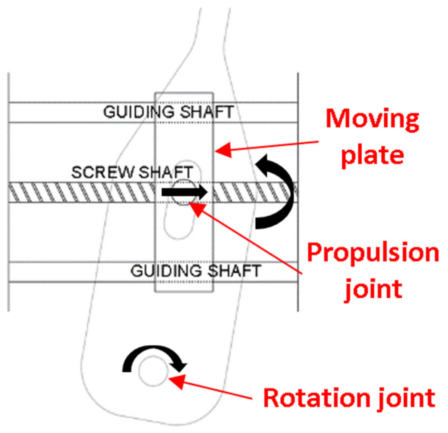
2.2.2. General Description of the Motorised Lever System

A description of the function and the essential elements of the otorized lever system follows. In the picture below (Figure 6), the basic parts of the system are tagged to offer a better understanding.
Lever grips are fabricated from firm elastic polymer and the different colouring offers a better perception of position from user’s peripheral vision. The base of each lever grip is mounted on a load cell, which is bolted on top of the lever body. Load cells are sensors that respond in linear proportion to the strain applied on them (Figure 7a). The specific load cells that were used have a nominal maximum measuring load of 100 kg. These strain sensors produce analog signals that are acquired and converted to the proportional force. The lever body is fabricated from aluminum and is painted in black color. It is also coated with a soft black foam polymer sheet, creating a surface similar to a protective cushion.
The kinetic power that is necessary to counteract the user’s resistance is offered to each lever through an electric step motor (Figure 7b). The rotative power of the motor is transmitted to the motion system of each lever via a belt, surrounded by a protective covering (Figure 7c). This design configuration significantly reduces the propagated vibrations of the motor to the screw shaft. It should be noted that a transmission ratio of 1:1 was selected for the belt.
The innovative design of the motion system allows for a lightweight construction, where the size and maximum power of the electric motors, gears, power supplies and other supporting elements—which are usually heavy—are kept to a minimum size. If the levers were propelled through its center of rotation, the required torque for the operation would be significantly large. For this reason, the motion system of the levers is engineered, as displayed in Figure 8. Each lever rotates freely around a rotation joint, and a propulsion joint is mounted on a moving plate and forces the lever to move. The moving plate is guided through a pair of linear guiding shafts and a rotating screw shaft–ball screw system. The direction of rotation of the step motor defines the direction of rotation of the screw shaft, thus resulting in the direction of the motion of the lever.
While the motion of the step motors is fully controllable, sometimes small distortions occur, especially when actual conditions shortly exceed operational range conditions. For this reason, the motorised lever system performs during operation a calibration procedure in every repetition. Two proximity sensors (Figure 6) serve this purpose for each lever system. In every repetition, when the step motors motion commands are terminated, commands for the proximity sensors to measure levers’ actual position follow. The position values are acquired from the controller inside the control box, are compared to the supposed positions and then a quick repositioning takes place. The correction of the position is usually zero, or fluctuates in a scale of magnitude of a couple of millimeters. This process ensures that levers will not move out of range due to small dispositionings that sometimes occur and can finally sum up. Additional technical information and design parameters of the motorised lever system are described in Appendix A.

2.2.3. Technical Description of the Control Box

Another essential part for the operation of the FIT-WHEEL device is the control box. It is manufactured from bended steel sheet parts that are electrostatically painted and assembled with the use of screws. The box provides properly configured slots that serve the placement of a power plug and an on/off button as well as the routing of input and output cables for signal, power and data transmission. It is used as a protective casing that contains electric and electronic components that serve the operation of the two motorised lever systems and are described below.
A development board Arduino Mega 2560 (Figure 9a) is used as the controlling system of the FIT-WHEEL device. The ATmega2560 microcontroller microchip that is embedded on the board is loaded with a purpose-built microcode that serves all the functions of FIT-WHEEL and provides interconnectivity with smart devices, through a USB port, offering a variety of operational features. Among the functions that the controller serves are the following:
  • Analog to digital signal acquisition from the embedded loadcells on the lever grips;
  • Motion command outputs for the step motors of the lever systems;
  • USB interconnectivity for real time data input and output;
  • Proximity sensors signal acquisition and lever positioning calibration process coordination.
This specific development board functions in the voltage level of 5V DC, so every direct electric interaction with the board, such as power input, input signal and output signal, are also set to function at 5V DC.
The motion control of each step motor is carried out using a DQ542MA step motor driver (Figure 9b). This is a device that provides female plugs for the electric power input, the motion command input and the inverted power output to the step motor. The electric power input is 48V DC, in sequence with the nominal maximum voltage that the selected step motors are designed for. The motion commands are dictated by the microcontroller, as described above and are provided as electric pulse signals of 5V. The power output to the step motor are the exact pulse signals that are provided as motion commands, inverted to the voltage level of the power input, which is 48V.
The DC electric power supply of 48V (Figure 9c) is also mounted on the internal of the steel sheet of the box in a way that the cooling fan inlet area gets a direct external air supply. The electric supply device is connected to the control box external power plug and converts the electrical grid power to 48V DC. The device has a power output of 500Watts, mainly consumed by the step motors that require such a scale of magnitude of electric power for their function.
Finally, a custom electronic board was designed and built with the use of an electronics prototyping breadboard. This electronic board is powered by the 48V DC power supply and includes voltage regulators for the conversion of the voltage input of 48V DC to an output of 10V DC and 5V DC. The output of 10V is used for the excitation of the loadcells that are embedded to the lever grips. The 5V output powers the microcontroller board and the proximity sensors. The total power output of the regulators is about 5Watts.

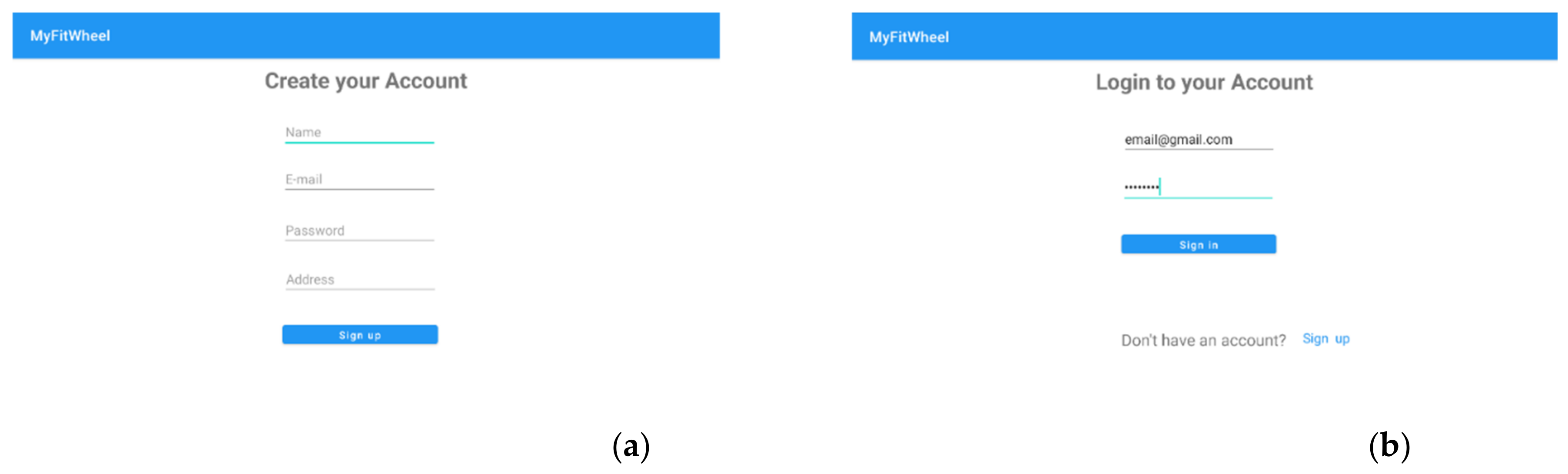
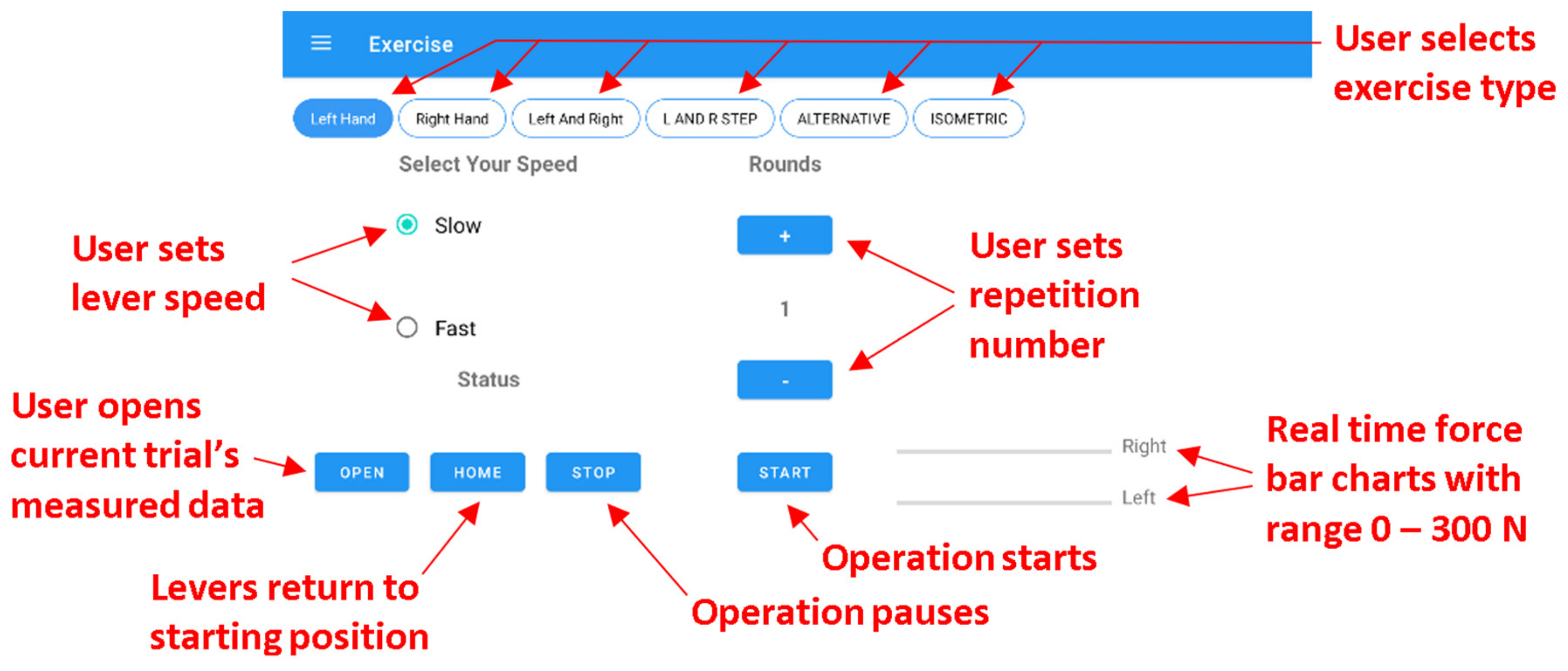
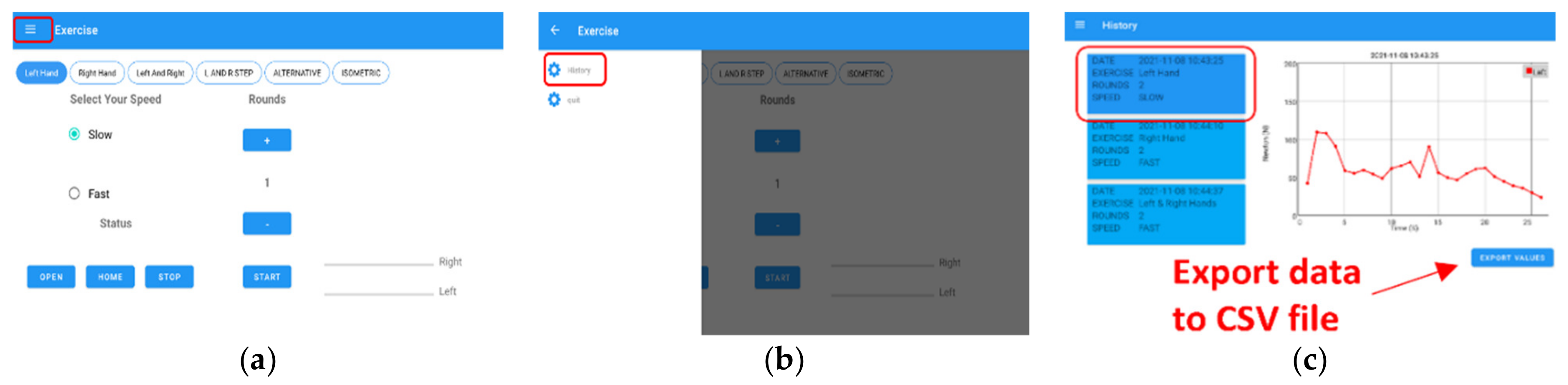
2.2.4. FIT-WHEEL Supporting Software Description

Android smart devices, such as tablets or smart phones, can be used through a USB cable that is connected to the development board USB port and the micro-USB port of the smart devices. An application (app) is developed that can be loaded to every android smart device and control the operation of FIT-WHEEL. Each user creates an account (Figure 10a) and can log in (Figure 10b) to access the control panel of the app.
When users access the control panel, they can select various features (Figure 11). The bar of features on top sets the type of exercise that the user prefers to practice. The first three choices correspond to exercising eccentrically or concentrically both upper extremities, or separately the left or right extremity. “L AND R STEP” feature offers the choice of exercising left and right extremities periodically, with intermediate breaks of 5 s. In “ALTERNATIVE” choice levers operate in a countermovement motion pattern. In “ISOMETRIC” option, the levers can be moved to different stationary positions and the user applies force isometrically. Several other features are available, such as to set the levers speed as “fast” or “slow”, the number of repetitions per session as well as real time force evaluation based on the applied force on the lever grips.
Users can also access previous training sessions data, which are logged to their account, through the menu presented in Figure 12. These data are stored in an online database and can also be accessed from other smart devices on which the app is installed. It should be noted that an administrator version of the app is also currently being tested, on which additional features are included. The administrator has the option to access the exercise data of multiple users, which can be used for rehabilitation or research purposes. Finally, datasets can be exported to CSV files for further processing.

2.3. Experimental Testing

2.3.1. Participants

As part of a larger study comparing the metabolic and cardiorespiratory responses between eccentric and concentric exercise on FIT-WHEEL, its usability was evaluated in eleven (n = 11) healthy, moderately active, male physical education students (age: 21.1 ± 1.7 years; body height: 180.9 ± 4.7 cm; body mass: 77.7 ± 3.6 kg). The volunteers were instructed to refrain from any unaccustomed strenuous exercise of the upper extremities (e.g., eccentric exercise) and not to use any analgesic medications or nutritional supplements during the experimental testing. The study was conducted in line with the principles of the Declaration of Helsinki. Approval was also obtained by the Ethics Committee of the Department of Physical Education and Sport Science at University of Thessaly, Greece (Date 13/10/2021/Ref. No. 3-1). A signed consent form was obtained from all the volunteers prior to their participation in the experimental procedure.

2.3.2. Experimental Protocol

The participants visited the biomechanics laboratory on three different occasions at the same time of the day. During the first visit, the participants initially were instructed on proper concentric/eccentric exercise technique and were familiarized with the operation of the novel lever exercise system. The intensity of exercise was progressively increased during familiarization trials to avoid muscle soreness, similarly to previous studies employing eccentric exercise of the upper or lower extremities [18,19,24,25]. Additionally, baseline peak concentric (PeakCON) and peak eccentric (PeakECC) force measurements of both upper extremities were collected, as the participants pushed (i.e., performing concentric actions) or resisted (i.e., performing eccentric actions) synchronously both levers by applying maximum voluntary force throughout the range of motion with a constant angular velocity. Participants sat in the wheelchair with the wheels locked in place and the position regulator (Figure 4) was adjusted individually so that the user’s upper extremities come to a safe and comfortable range of motion, without reaching full elbow extension. The constant velocity used was the “slow” speed option provided by the FIT-WHEEL system and set as aforementioned at VSLOW = 5.75 cm/sec. During the second and third visits (7 days apart), the participants performed in random order a moderate intensity concentric and eccentric exercise protocol consisting of 30 trials of both upper extremities at 30% of PeakCON or PeakECC, respectively. At the end of each exercise bout, participants completed a number of valid and reliable instruments examining attitudes, intention and enjoyment during concentric or eccentric exercise on the FIT-WHEEL system as well as the usability of the two exercise protocols on the novel lever-driven exercise system. Moreover, the total mechanical work during concentric and eccentric exercise was calculated to compare the mechanical work differences between the two exercise protocols employed.

2.3.3. Instruments

To test the applicability of the FIT-WHEEL upper extremities exercise system the following instruments were delivered immediately after the concentric and eccentric exercise protocols, respectively:
  • Attitudes. Six items were employed to evaluate attitudes towards exercise with the FIT-WHEEL system based on Ajzen’s [26,27] recommendations and previous studies in new technology systems [28]. Participants’ responses were given on a 7-point Likert scale from 1 (“I find concentric or eccentric exercise with the FIT-WHEEL system … very bad or very useless or very unpleasant”) to 7 (“I find concentric or eccentric exercise with the FIT-WHEEL system … very good or very useful or very pleasant”);
  • Intention. Three items were used to capture participants’ intention to use the FIT-WHEEL system based on Ajzen’s [26,27] guidelines and previous research [28] (e.g., “I intend to use the FIT-WHEEL system for exercise” or “If I gain access, I intent to use the FIT-WHEEL system for exercise”). All answers were given on a 7-point Likert scale from 1 (Very Unlikely) to 7 (Very Likely);
  • Enjoyment. Four items of the Intrinsic Motivation Inventory’s enjoyment subscale [29] were used to assess participants’ enjoyment while exercising concentrically or eccentrically with the FIT-WHEEL system (e.g., “I enjoyed concentric or eccentric exercise with the FIT-WHEEL system very much” or “Exercising concentrically or eccentrically with the FIT-WHEEL system was fun”). The participants responded on a 5-point Likert scale from 1 (Strongly Disagree) to 5 (Strongly Agree);
  • Usability. A short and modified version of Brooke’s usability scale [30] was used to assess the FIT-WHEEL system’s usability during the concentric and eccentric exercise protocols. Totally, seven items were delivered to capture participants’ perceived usability of the FIT-WHEEL system (e.g., “I thought that the FIT-WHEEL system was easy to use” or “I found the FIT-WHEEL system very complex”), while their responses were given on a 5-point Likert scale ranging from 1 (Strongly Disagree) to 5 (Strongly Agree). Participants’ responses in three items with a negative meaning (e.g., “I found the FIT-WHEEL system very complex”) were revised.
It is important to mention that all the above-mentioned instruments have already been translated into the Greek language and have been used previously in studies with a Greek population [31,32,33].

2.3.4. Statistical Analyses

The IBM SPSS Statistics software version 26 was used to analyse the data. The level of significance was set at p < 0.05. Shapiro-Wilks test was initially used to check normal distribution in both exercise protocols (concentric, eccentric). Results showed that the variables of total mechanical work, intention to use and usability of the FIT-WHEEL system had normal distribution (p > 0.05), while the variables of attitudes towards exercise with the FIT-WHEEL system and enjoyment during exercise with the FIT-WHEEL system were not normally distributed (p < 0.05). Descriptive statistics (means and standard deviations) as well as Cronbachs’ α reliability index and Spearman’s correlations among the examined variables in both exercise protocols were also calculated. Then, separate paired samples t-tests were computed to explore possible differences between concentric and eccentric exercise protocols on total mechanical work, intention to use the FIT-WHEEL system and its usability. Finally, separate Wilcoxon signed-rank non-parametric tests were used to examine possible differences between concentric and eccentric exercise protocols on attitudes towards exercise with the FIT-WHEEL system and enjoyment during exercise with the FIT-WHEEL system.

3. Results

Descriptive statistics, Cronbach’s α reliability index, and Shapiro-Wilks test for checking normality regarding attitudes, intention, enjoyment and usability variables in both exercise protocols (concentric, eccentric) are presented in Table 1. Reliability analysis showed acceptable values (α > 0.70) in most of the examined variables. Correlation analysis with Spearman’s index showed high correlations between concentric and eccentric exercise protocols for participants’ enjoyment (rs = 0.604, p < 0.05), intention (rs = 0.842, p ≤ 0.001), and attitudes (rs = 0.847, p ≤ 0.001), but not for the usability scale (rs = 0.124, p = 0.716).
Paired samples t-tests showed that total mechanical work (averaged for left and right upper extremity) during concentric exercise was 18.3% lower compared to eccentric exercise performed on the FIT-WHEEL training system (t10 = −4.69, p = 0.001). Moreover, paired samples t-tests revealed no significant differences between concentric and eccentric exercise protocols on intention to use the FIT-WHEEL system (t10 = −1.067, p = 0.311) and its usability (t10 = −1.564, p = 0.149). Similarly, Wilcoxon signed-rank tests revealed no significant differences between concentric and eccentric exercise protocols on attitudes towards exercise (Z = −1.132, p = 0.257) and enjoyment during exercise with the FIT-WHEEL system (Z = −1.777, p = 0.08). Detailed results for every participant regarding attitudes, intention, enjoyment and usability variables in both exercise protocols are given in Table 2.

4. Discussion

A lever-driven quasi-isokinetic exercise system was developed with the potential to improve upper body strength and aerobic capacity while performing eccentric, concentric or isometric actions of the upper extremities. FIT-WHEEL’s inexpensive design is based on two motorised levers, to the left and to the right of the user, one for each upper extremity. Each lever system is an independent mechanical construction that is built from smaller parts easily found on the market, such as electric step motors, step motor drivers, guide shafts, screw shafts, bearings etc. Both lever systems are mounted on a properly designed and constructed steel frame and are connected to a power supply and a microcontroller that dictates commands for the motion patterns of the levers. The microcontroller also acquires the analog signals of two load cells, embedded in the hand grips of the levers, which measure the reaction force of the user during training repetitions. Hand force measurements serve both data collection and the integration of the system with real-time interactive applications to provide feedback to the user. Other mechanical elements are also included on the device, such as a user position regulator, which contribute to a safe and ergonomic function. The acronym FIT-WHEEL incorporates the project’s major concepts, that are Functional, “Intelligent” Training system for Wheelchair users.
FIT-WHEEL is functional because it is designed to be able to accommodate each user’s specific needs by applying the eccentric, concentric or isometric training mode with individualized intensity and duration of exercise and can be used at each user’s own safe and accessible home environment. FIT-WHEEL users can access the device and exercise with it, while being on their wheelchairs, so that they do not require any kind of assistance. A novel advantage of the FIT-WHEEL system is the integration of the benefits of eccentric exercise [20,21] and lever-driven wheelchair operation [12] while training the upper extremities. Compared to concentric exercise, the eccentric phase of exercise takes place while muscles lengthen under tension. This type of exercise offers a functional advantage compared to conventional concentric training, due to low-energy cost of force production and subsequent lower fatigue of the trainee [21]. Given that less effort is necessary, it is easier for the users to train more frequently and mark more extensive exercise results. For the first time a specialized exercise modality for wheelchair users is developed emphasizing eccentric exercise in combination with the less strenuous [12,23] lever-driven wheelchair operation. Considering that total mechanical work during eccentric exercise was found in our experimental testing to be 18.3% higher compared to concentric exercise performed with equivalent intensity on the FIT-WHEEL training system, strength capacity and physical health in general has the potential to be improved efficiently without risking injuring the upper extremities of the end users.
The acronym of the exercise system includes the term “intelligent”, because FITWHEEL can support the rehabilitation process on a personalized basis, providing real-time and archived individual feedback via the FIT-WHEEL app operated on smart devices. A new app version is currently developed which can also integrate with real-time interactive video games and provide gamified exercise by pushing or resisting the levers. The integration of the FIT-WHEEL system with a gamified environment can contribute to an enjoyable and meaningful participation in a virtual community while exercising and increase motivation and adherence [34].
A second purpose of the present study was to examine the usability and feasibility of the FIT-WHEEL system while employing the eccentric and concentric exercise mode in healthy individuals. According to Sauro et al. [35], “usability is defined as a combination of the users’ perception of efficiency, effectiveness, and satisfaction of a product within a specific intended context and is critical to facilitate uptake of any new technology”. The preliminary findings of our study revealed high scores in all the examined parameters (attitudes, intention, enjoyment, usability) in both eccentric and concentric exercise protocols, without any significant differences emerging between them. It seems that both exercise protocols on the FIT-WHEEL system were usable and tolerable in a specific sample of young, healthy, male adults, even though the mechanical work during the eccentric protocol was higher compared to the respective concentric protocol. This observation is in line with the research group of Elmer et al. [16,18,19] who also found no significant differences on usability and likeability between eccentric and concentric arm cycling in healthy participants as well as in individuals with spinal cord injury.
A limitation given the preliminary nature of the present study was the small sample size (n = 11) of the recruited group of healthy, male individuals. This may explain the low reliability values obtained in some of the examined variables, particularly in the usability scale. Additional research is needed to determine the usability of the proposed lever-driven exercise system and the feasibility to induce long-term health benefits in a larger population that will also include female participants as well as wheelchair users (e.g., individuals with spinal cord injury or various upper extremities impairments). A next step would be to explore if the implementation of a lever-driven eccentric exercise training intervention can enhance wheelchair specific fitness [36,37] and everyday functional capacity of the users (e.g., lever propelled wheelchair propulsion efficiency), and decrease shoulder pain by improving force distribution between the anterior and posterior upper extremities muscles. Moreover, given that FIT-WWHEEL is a prototype construction under testing, a next version could offer more safety provisions, better functionality and durability. Future improvement goals may include (a) the development of easily accessible emergency stop buttons close to both upper limbs and/or touch sensors that would identify the removal of hands from lever grips and automatically stop the motion of levers to avoid injuries of the end users and (b) a more lightweight construction and faster moving levers.

5. Conclusions

This paper highlighted the design, construction, and technical aspects of a new lever-driven quasi-isokinetic exercise system that can be used while performing eccentric, concentric or isometric actions of the upper extremities. The application of the FIT-WHEEL system in healthy male individuals showed that both eccentric and concentric exercise modes were perceived usable, safe and likable, and potentially can be used as an alternative training modality to improve upper body strength and aerobic capacity. A novel advantage of the proposed system compared to commercially available exercise options is the integration of the benefits of eccentric exercise as well as the mechanically efficient and less injurious lever-driven wheelchair operation while training the upper body. The preliminary experimental results discussed serve as an initial step to implement lever-driven eccentric exercise in wheelchair dependent populations in the future and evaluate potential long-term benefits and limitations.

6. Patents

Patent requests have been submitted to the Industrial Property Organisation (Greece) and to the European Patent Office (EPO).

Author Contributions

Conceptualization, T.T.; methodology, T.T. and C.K. (Charalampos Krommidas); software, F.T., A.P. and C.F.; validation, G.B, F.T., A.P., C.K. (Christos Kokkotis). and T.T.; investigation, T.T., E.K. and C.K. (Charalampos Krommidas); data curation, C.K. (Charalampos Krommidas) and C.K. (Christos Kokkotis); writing—original draft preparation, T.T., G.B. and C.K. (Charalampos Krommidas); writing—review and editing, T.T., A.Z.J. and G.G.; visualization, G.B.; supervision, T.T. and G.G.; project administration, T.T.; funding acquisition, T.T. All authors have read and agreed to the published version of the manuscript.

Funding

This research has been co-financed by the European Regional Development Fund of the European Union and Greek national funds through the Operational Program Competitiveness, Entrepreneurship and Innovation, under the call RESEARCH–CREATE–INNOVATE (project code: T1EDK-05425).

Institutional Review Board Statement

The study was conducted according to the guidelines of the Declaration of Helsinki, and approved by the Ethics Committee of the University of Thessaly (protocol code 3-1 and date of approval 13 October 2021).

Informed Consent Statement

Informed consent was obtained from all subjects involved in the study.

Data Availability Statement

The data collected and analysed during the study are not publicly available, but are available from the corresponding author on reasonable request.

Conflicts of Interest

The authors declare no conflict of interest. The funders had no role in the design of the study; in the collection, analyses, or interpretation of data; in the writing of the manuscript; or in the decision to publish the results.

Appendix A

On this section part, a closer look on technical information and design parameters of the motorised lever system is provided. An essential design parameter for FIT-WHEEL device is that the motion pattern of the levers resembles linear motion. Specifically, levers move in a total arc of 20° (Figure A1a). Because of the slight angle of rotation that is ±10° of the central position, the motion during exercising, is like linear motion pattern. Given that the length of each lever from the center of rotation to the top of the grip is 83 cm (Figure A1b), moving in a range of an arc of ±10° resembles an almost linear displacement of total of 27 cm, that is considered an ergonomic range of motion for the average sized human body.
As linear displacement of the propulsion joint causes an almost proportionate linear displacement of the top of the levers grip, it is expected that these two points will move in an analogy of their distances from the rotation joint. This also applies to the moving velocity of the two points. Furthermore, the application of force on the top of the grip loads the propulsion joint on an inverse proportion of these distances. For example, a displacement of 1cm of the propulsion joint, will cause a displacement of the top of lever’s grip, of 6.9 cm, in a respective velocity of 6.9 m/sec. Consequently, a force of 6.9N applied by the user on the top of lever’s grip, will cause the occurrence of a load of 1N on the propulsion joint. Force and velocity of the propulsion joints are defined through the step motors’ RPM (i.e., revolutions per minute for the rotating shaft) and the maximum rotational torque that is finally conveyed as linear force on the screw shaft–ball screw system that drives the propulsion joint. Step motors that were selected for FIT-WHEEL manufacturing, are ACT 23HS8440-23 step motors, with step angle of 1.8°, and two phases that operate in 48V and 4A per phase. Essential parameters for the function of the system are mentioned bellow:
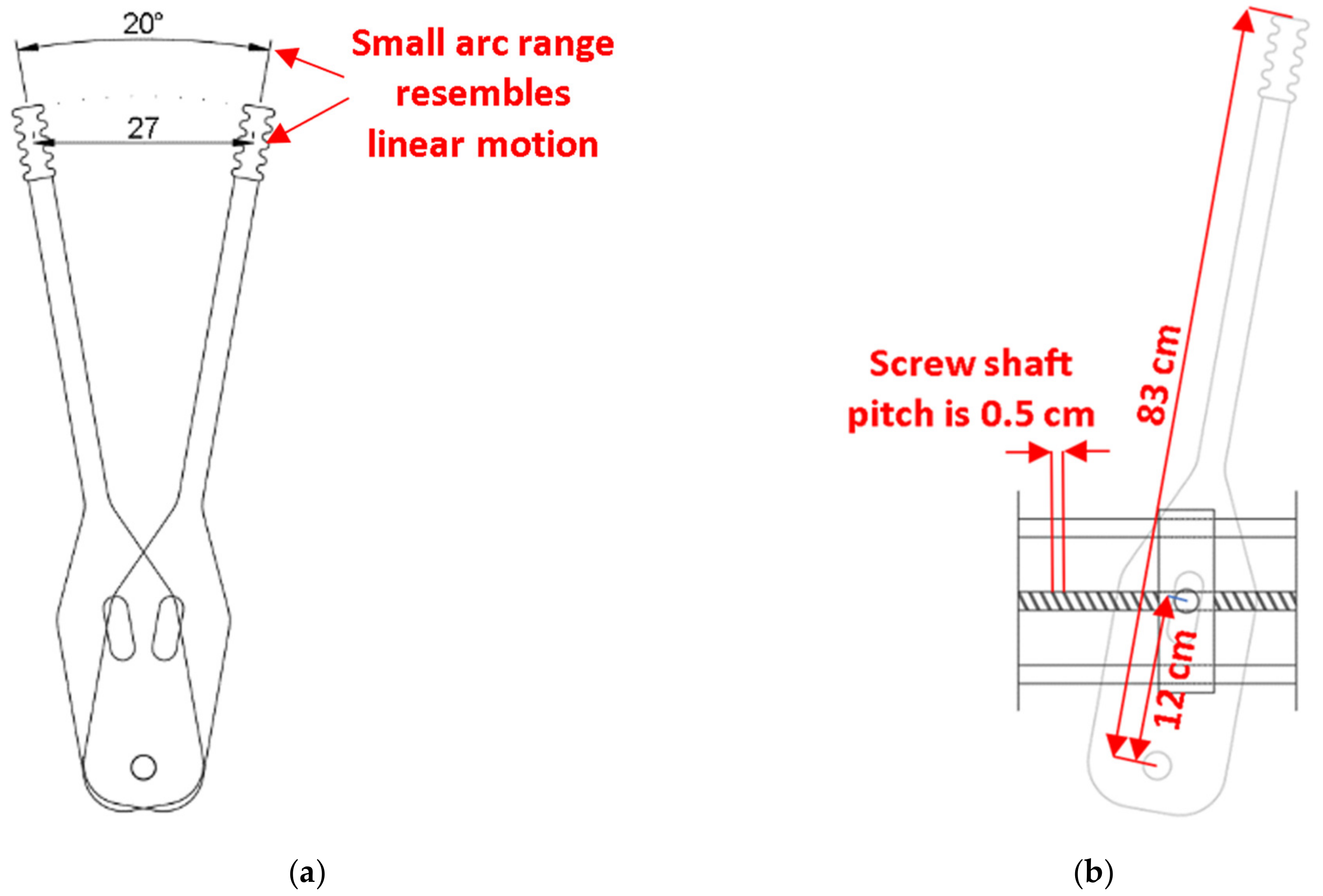
  • The transmission ratio of the transmission belt is 1:1;
  • Each power lever system is set to operate in two different speeds, where the “fast” and the “slow” speed respectively correspond to 200 RPM and 100 RPM for the motor shaft.
Figure A1. (a) Pattern of motion is almost linear; (b) Dimensions of each power lever system.
Biomed 03 00003 g0a1
The following formula converts the torque of the screw axis, that is powered by the step motor, in linear force of the propulsion joint: F = T × 2 × pi/L where F is the linear force, T is screw axis torque and L is the axial pitch of the screw shaft, which is 0.5 cm as presented in Figure A1b for the specific shaft selected. As a result, the maximum nominal load that FIT-WHEEL prototype is designed for, according to the given formula, is F = 2,072 N. As mentioned above, the force on the propulsion joint is inversely proportionate to the force on the top part of the levers’ grip, by 6.9 times. Consequently, Fmax = 300 N, where Fmax is the maximum load that can occur to the top part of levers’ grip as a reaction force from the user, until maximum torque is reached to the step motor shafts and they stop rotating. Based on the mentioned operating conditions and the described geometrical characteristics of the mechanical elements of the motorised lever systems, “fast” and “slow” speed of the motors cause the top point of the lever grips to move under the speed of VFAST = 11.5 cm/sec and VSLOW = 5.75 cm/sec, respectively.

References

  1. Selph, S.S.; Skelly, A.C.; Wasson, N.; Dettori, J.R.; Brodt, E.D.; Ensrud, E.; Elliot, D.; Dissinger, K.M.; McDonagh, M. Physical Activity and the Health of Wheelchair Users: A Systematic Review in Multiple Sclerosis, Cerebral Palsy, and Spinal Cord Injury. Arch. Phys. Med. Rehabil. 2021, 102, 2464–2481.e2433. [Google Scholar] [CrossRef] [PubMed]
  2. Smith, E.M.; Sakakibara, B.M.; Miller, W.C. A review of factors influencing participation in social and community activities for wheelchair users. Disabil. Rehabil. Assistive Technol. 2016, 11, 361–374. [Google Scholar] [CrossRef] [PubMed] [Green Version]
  3. Valent, L.; Dallmeijer, A.; Houdijk, H.; Talsma, E.; van der Woude, L. The effects of upper body exercise on the physical capacity of people with a spinal cord injury: A systematic review. Clin. Rehabil. 2007, 21, 315–330. [Google Scholar] [CrossRef] [PubMed]
  4. Miller, L.E.; Herbert, W.G. Health and economic benefits of physical activity for patients with spinal cord injury. Clin. Outcomes Res. 2016, 8, 551–558. [Google Scholar] [CrossRef] [PubMed] [Green Version]
  5. Van Koppenhagen, C.F.; Post, M.; De Groot, S.; Van Leeuwen, C.; Van Asbeck, F.; Stolwijk-Swüste, J.; Van Der Woude, L.; Lindeman, E. Longitudinal relationship between wheelchair exercise capacity and life satisfaction in patients with spinal cord injury: A cohort study in the Netherlands. J. Spinal Cord Med. 2014, 37, 328–337. [Google Scholar] [CrossRef] [Green Version]
  6. Martin Ginis, K.A.; Latimer, A.E.; Arbour-Nicitopoulos, K.P.; Buchholz, A.C.; Bray, S.R.; Craven, B.C.; Hayes, K.C.; Hicks, A.L.; McColl, M.A.; Potter, P.J.; et al. Leisure Time Physical Activity in a Population-Based Sample of People With Spinal Cord Injury Part I: Demographic and Injury-Related Correlates. Arch. Phys. Med. Rehabil. 2010, 91, 722–728. [Google Scholar] [CrossRef]
  7. Roberton, T.; Bucks, R.S.; Skinner, T.C.; Allison, G.T.; Dunlop, S.A. Barriers to Physical Activity in Individuals with Spinal Cord Injury: A Western Australian Study. Aust. J. Rehabil. Couns. 2011, 17, 74–88. [Google Scholar] [CrossRef]
  8. Scelza, W.M.; Kalpakjian, C.Z.; Zemper, E.D.; Tate, D.G. Perceived barriers to exercise in people with spinal cord injury. Am. J. Phys. Med. Rehabil. 2005, 84, 576–583. [Google Scholar] [CrossRef]
  9. Lee, S.Y.; Lee, J.A.; Chung, H.J.; Kim, H.J.; Kim, Y.C.; Kim, H. Subjective Perception of Individuals with Physical Disabilities Regarding Exercise Equipment Use. Inquiry (United States) 2021, 58, 00469580211010429. [Google Scholar] [CrossRef]
  10. Sawatzky, B.; Herrington, B.; Choi, K.; Ben Mortenson, W.; Borisoff, J.; Sparrey, C.; Laskin, J.J. Acute physiological comparison of sub-maximal exercise on a novel adapted rowing machine and arm crank ergometry in people with a spinal cord injury. Spinal Cord 2022, 60, 694–700. [Google Scholar] [CrossRef]
  11. Wong, R.N.; Stewart, A.L.; Sawatzky, B.; Laskin, J.J.; Borisoff, J.; Mattie, J.; Sparrey, C.J.; Mortenson, W.B. Exploring exercise participation and the usability of the adaptive rower and arm crank ergometer through wheelchair users’ perspectives. Disabil. Rehabil. 2021, 44, 3915–3924. [Google Scholar] [CrossRef]
  12. Flemmer, C.L.; Flemmer, R.C. A review of manual wheelchairs. Disabil. Rehabil. Assistive Technol. 2016, 11, 177–187. [Google Scholar] [CrossRef]
  13. Pelletier, C.A.; Ditor, D.S.; Latimer-Cheung, A.E.; Warburton, D.E.; Hicks, A.L. Exercise equipment preferences among adults with spinal cord injury. Spinal Cord 2014, 52, 874–879. [Google Scholar] [CrossRef] [Green Version]
  14. Bjerkefors, A.; Tinmark, F.; Nilsson, J.; Arndt, A. Seated double-poling ergometer performance of individuals with spinal cord injury—A new ergometer concept for standardized upper body exercise. Int. J. Sports Med. 2013, 34, 176–182. [Google Scholar] [CrossRef]
  15. Ye, G.; Grabke, E.P.; Pakosh, M.; Furlan, J.C.; Masani, K. Clinical Benefits and System Design of FES-Rowing Exercise for Rehabilitation of Individuals with Spinal Cord Injury: A Systematic Review. Arch. Phys. Med. Rehabil. 2021, 102, 1595–1605. [Google Scholar] [CrossRef]
  16. Elmer, S.J.; Marshall, C.S.; McGinnis, K.R.; Van Haitsma, T.A.; Lastayo, P.C. Eccentric arm cycling: Physiological characteristics and potential applications with healthy populations. Eur. J. Appl. Physiol. 2013, 113, 2541–2552. [Google Scholar] [CrossRef]
  17. Elmer, S.J.; Danvind, J.; Holmberg, H.C. Development of a novel eccentric arm cycle ergometer for training the upper body. Med. Sci. Sports Exerc. 2013, 45, 206–211. [Google Scholar] [CrossRef]
  18. Elmer, S.J.; Anderson, D.J.; Wakeham, T.R.; Kilgas, M.A.; Durocher, J.J.; Lindstedt, S.L.; LaStayo, P.C. Chronic eccentric arm cycling improves maximum upper-body strength and power. Eur. J. Appl. Physiol. 2017, 117, 1473–1483. [Google Scholar] [CrossRef]
  19. Lytle, L.L.; Dannenbring, J.L.; Kilgas, M.A.; Elmer, S.J. Eccentric Arm Cycling: A Potential Exercise for Wheelchair Users. Arch. Phys. Med. Rehabil. 2019, 100, 914–922. [Google Scholar] [CrossRef]
  20. Hoppeler, H. Moderate load eccentric exercise; A distinct novel training modality. Front. Physiol. 2016, 7, 483. [Google Scholar] [CrossRef]
  21. LaStayo, P.; Marcus, R.; Dibble, L.; Frajacomo, F.; Lindstedt, S. Eccentric exercise in rehabilitation: Safety feasibility, and application. J. Appl. Physiol. 2014, 116, 1426–1434. [Google Scholar] [CrossRef] [PubMed] [Green Version]
  22. Liampas, A.; Neophytou, P.; Sokratous, M.; Varrassi, G.; Ioannou, C.; Hadjigeorgiou, G.M.; Zis, P. Musculoskeletal Pain Due to Wheelchair Use: A Systematic Review and Meta-Analysis. Pain Ther. 2021, 10, 973–984. [Google Scholar] [CrossRef] [PubMed]
  23. Skendraoui, N.; Bogard, F.; Murer, S.; Ahram, T.Z.; Fiok, K.; Taiar, R. The musculoskeletal contribution in wheelchair propulsion systems: Numerical analysis. In AHFE International Conference on Ergonomics in Design, 2018; Springer: Cham, Switzerland, 2019; Volume 777, pp. 251–260. [Google Scholar] [CrossRef]
  24. Tsatalas, T.; Karampina, E.; Mina, M.A.; Patikas, D.A.; Laschou, V.C.; Pappas, A.; Jamurtas, A.Z.; Koutedakis, Y.; Giakas, G. Altered Drop Jump Landing Biomechanics Following Eccentric Exercise-Induced Muscle Damage. Sports 2021, 9, 24. [Google Scholar] [CrossRef] [PubMed]
  25. Tsatalas, T.; Giakas, G.; Spyropoulos, G.; Sideris, V.; Kotzamanidis, C.; Koutedakis, Y. Walking kinematics and kinetics following eccentric exercise-induced muscle damage. J. Electromyogr. Kinesiology 2013, 23, 1229–1236. [Google Scholar] [CrossRef] [PubMed]
  26. Ajzen, I. Constructing a Theory of Planned Behavior Questionnaire. Available online: https://people.umass.edu/aizen/pdf/tpb.measurement.pdf (accessed on 10 May 2022).
  27. Ajzen, I. Attitudes, Personality and Behavior, 2nd ed.; Open University Press/McGraw-Hill: Maidenhead, England, 2005. [Google Scholar]
  28. Rasimah, C.M.Y.; Ahmad, A.; Zaman, H.B. Evaluation of user acceptance of mixed reality technology. Australas. J. Educ. Technol. 2011, 27, 1369–1387. [Google Scholar] [CrossRef]
  29. McAuley, E.D.; Duncan, T.; Tammen, V.V. Psychometric properties of the intrinsic motivation inventoiy in a competitive sport setting: A confirmatory factor analysis. Res. Q. Exerc. Sport 1989, 60, 48–58. [Google Scholar] [CrossRef]
  30. Brooke, J. SUS—A quick and dirty usability scale. In Usability Evaluation in Industry; Jordan, P.W., Thomas, B., McClelland, I.L., Weerdmeester, B., Eds.; Taylor & Francis Ltd.: Bristol, UK, 1996; pp. 189–194. [Google Scholar]
  31. Krommidas, C.; Galanis, E.; Tzormpatzakis, E.; Hasandra, M.; Hatzigeorgiadis, A.; Morres, I.D.; Comoutos, N.; Theodorakis, Y. The Effects of Acute Exercise and Virtual Reality Tasks on Children’s Memory Function and Exercise Preference. Int. J. Kinesiol. Sport. Sci. 2022, 10, 7–17. [Google Scholar] [CrossRef]
  32. Papacharisis, V.; Goudas, M. Perceptions about exercise and intrinsic motivation of students attending a health-related physical education program. Percept. Mot. Ski. 2003, 97, 689–696. [Google Scholar] [CrossRef]
  33. Touloudi, E.; Hassandra, M.; Galanis, E.; Goudas, M.; Theodorakis, Y. Applicability of an Immersive Virtual Reality Exercise Training System for Office Workers during Working Hours. Sports 2022, 10, 104. [Google Scholar] [CrossRef]
  34. Mat Rosly, M.; Mat Rosly, H.; Davis Oam, G.M.; Husain, R.; Hasnan, N. Exergaming for individuals with neurological disability: A systematic review. Disabil. Rehabil. 2017, 39, 727–735. [Google Scholar] [CrossRef]
  35. Sauro, J.; Lewis, J.R. Quantifying the User Experience: Practical Statistics for User Research; Morgan Kaufmann: Burlington, MA, USA, 2016. [Google Scholar]
  36. Van Der Scheer, J.W.; De Groot, S.; Tepper, M.; Gobets, D.; Veeger, D.H.E.J.; Van Der Woude, L.H.V.; Woldring, F.; Valent, L.; Slootman, H.; Faber, W. Wheelchair-specific fitness of inactive people with long-term spinalcord injury. J. Rehabil. Med. 2015, 47, 330–337. [Google Scholar] [CrossRef] [Green Version]
  37. Haisma, J.A.; Van Der Woude, L.H.V.; Stam, H.J.; Bergen, M.P.; Sluis, T.A.R.; Bussmann, J.B.J. Physical capacity in wheelchair-dependent persons with a spinal cord injury: A critical review of the literature. Spinal Cord 2006, 44, 642–652. [Google Scholar] [CrossRef]
Figure 1. An overview of the device.
Biomed 03 00003 g001
Figure 2. Front view of the device.
Biomed 03 00003 g002
Figure 3. (a) Rear view of the device; (b) proper positioning of the user, ensuring a safe and ergonomic position during exercise.
Biomed 03 00003 g003
Figure 4. An overview of safety parameters taken into account during the design of the device.
Biomed 03 00003 g004
Figure 5. 3D drawing of the steel frame during the design process.
Biomed 03 00003 g005
Figure 6. Basic parts of the otorized lever systems.
Biomed 03 00003 g006
Figure 7. (a) 100 kg Load cells measure the reaction force on the hand grips; (b) electric step motors power the levers; (c) power is transmitted from motors through belts.
Biomed 03 00003 g007
Figure 8. Mechanical parts of the levers motion system.
Biomed 03 00003 g008
Figure 9. (a) Controller board; (b) step motor driver; (c) power supplies.
Biomed 03 00003 g009
Figure 10. (a) Sign up tab on FIT-WHEEL app; (b) sign in tab on FIT-WHEEL app.
Biomed 03 00003 g010
Figure 11. Control panel tab on the FIT-WHEEL app.
Biomed 03 00003 g011
Figure 12. (a) First; (b) second; (c) third step to access exercise data on the FIT-WHEEL app.
Biomed 03 00003 g012
Table 1. Descriptive statistics, reliability index, and Shapiro-Wilks test for checking normality in both exercise protocols (concentric and eccentric).
Exercise ProtocolVariablesM ± SDαShapiro-Wilksp-Value
Concentric exerciseAttitudes6.03 ± 0.820.900.8290.023
Intention5.00 ± 0.880.850.8930.153
Enjoyment4.07 ± 0.360.550.9550.707
Usability3.70 ± 0.450.560.8700.077
Eccentric exerciseAttitudes5.89 ± 0.570.790.8450.037
Intention5.18 ± 0.980.880.9720.905
Enjoyment3.84 ± 0.490.740.7930.008
Usability3.95 ± 0.310.520.9600.775
M = Mean; SD = Standard Deviation; α = Cronbach’s α reliability index.
Table 2. Descriptive statistics (means and standard deviations) and Shapiro-Wilks test for checking normality in both exercise protocols (concentric and eccentric).
Concentric Exercise ProtocolEccentric Exercise Protocol
AttitudesIntentionEnjoymentUsabilityAttitudesIntentionEnjoymentUsability
NM ± SDM ± SDM ± SDM ± SDM ± SDM ± SDM ± SDM ± SD
P16.33 ± 0.524.00 ± 1.004.75 ± 0.504.29 ± 0.536.17 ± 0.754.67 ± 0.584.50 ± 1.003.71 ± 0.49
P26.00 ± 1.106.00 ± 0.004.00 ± 0.823.14 ± 0.586.17 ± 0.756.33 ± 0.583.75± 0.503.43 ± 0.79
P36.50 ± 0.555.67 ± 0.584.50 ± 0.584.00 ± 0.586.50 ± 0.555.67 ± 0.584.50 ± 0.584.14 ± 0.38
P46.17 ± 0.984.33 ± 0.584.00 ± 0.823.14 ± 1.255.50 ± 1.223.33 ± 0.583.25 ± 0.504.00 ± 0.58
P56.00 ± 0.006.33 ± 0.584.00 ± 0.823.29 ± 0.696.00 ± 0.006.00 ± 0.004.50 ± 1.004.14 ± 0.69
P67.00 ± 0.005.00 ± 1.004.25 ± 0.504.29 ± 0.496.33 ± 0.525.00 ± 0.004.25 ± 0.504.43 ± 0.53
P76.67 ± 0.526.00 ± 0.003.75 ± 1.263.71 ± 0.956.33 ± 0.826.67 ± 0.583.50 ± 1.294.00 ± 0.58
P86.17 ± 0.755.00 ± 0.004.00 ± 0.824.00 ± 0.385.67 ± 0.525.00 ± 0.003.50 ± 0.584.00 ± 0.58
P96.33 ± 0.524.00 ± 1.004.25 ± 1.503.86 ± 0.696.17 ± 0.414.00 ± 1.003.50 ± 1.003.71 ± 0.49
P104.00 ± 0.894.67 ± 0.583.75 ± 0.503.14 ± 1.134.50 ± 1.055.33 ± 0.583.50 ± 0.584.29 ± 0.49
P115.17 ± 0.754.00 ± 1.003.50 ± 0.583.86 ± 0.005.50 ± 0.555.00 ± 1.003.50 ± 0.583.57 ± 0.53
N = Number of Participants; P1–P11 = Participants; M = Mean; SD = Standard Deviation.
Disclaimer/Publisher’s Note: The statements, opinions and data contained in all publications are solely those of the individual author(s) and contributor(s) and not of MDPI and/or the editor(s). MDPI and/or the editor(s) disclaim responsibility for any injury to people or property resulting from any ideas, methods, instructions or products referred to in the content.

