
Reference Electrodes

1
Institut für Chemie, Chemnitz University of Technology, D-09107 Chemnitz, Germany
2
Department of Electrochemistry, Institute of Chemistry, Saint Petersburg State University, 7/9 Universitetskaya nab., St. Petersburg 199034, Russia
3
State Key Laboratory of Materials-Oriented Chemical Engineering, School of Energy Science and Engineering, Nanjing Tech University, Nanjing 211816, China
*
Author to whom correspondence should be addressed.
Encyclopedia 2023, 3(2), 478-489; https://doi.org/10.3390/encyclopedia3020033
Submission received: 7 February 2023
/
Revised: 5 April 2023
/
Accepted: 10 April 2023
/
Published: 13 April 2023
(This article belongs to the Section Material Sciences)
Definition
:A reference electrode is a half-cell (an electrode) with a stable, well-defined and highly reproducible electrode potential. A vast number of electrodes have been developed for different applications. They are briefly presented. For the common types, the advantages and drawbacks are discussed. Practical hints for daily use are provided.
1. Introduction
In electrochemistry, an electronically (n-) conducting material (a metal, graphite, n-doped semiconductor, etc.) or hole-conducting (p-doped semiconductor) material brought into contact with ionically conducting material (an electrolyte solution, an ionic liquid, a solid ion conductor) forms an electrode. At the plane of contact, an electrochemical double layer (sometimes a slightly oversimplified electric double layer) is formed. Because the two phases are immiscible and have vastly different properties strongly related to the mobile charge carriers in both phases at the phase boundary, strong electric fields (with a field strength of up to 109 V·m−1) are established. Upon the initial contact, both phases may not be in thermodynamic equilibrium. Such equilibrium can be established by suitable redox reactions. Some species from the electronically conducting phase are oxidized, leaving negative charges behind, or some species from the ionically conducting phase may be reduced, taking up electrons from the other phase. In both cases (and more options are conceivable), differences in the electrostatic potentials in both phases (the Galvani potential difference) are established. The formation of the electrode potential is the result [1]. This definition of an electrode as being essentially equivalent to an electrochemical half cell is only one option [2]. Another one focuses entirely on the electronically conducting phase (a platinum electrode or a lead electrode), as specified in [3]. For reasons discussed elsewhere [4], this certainly simpler approach (because of shortness and convenience) is less precise, although more popular.
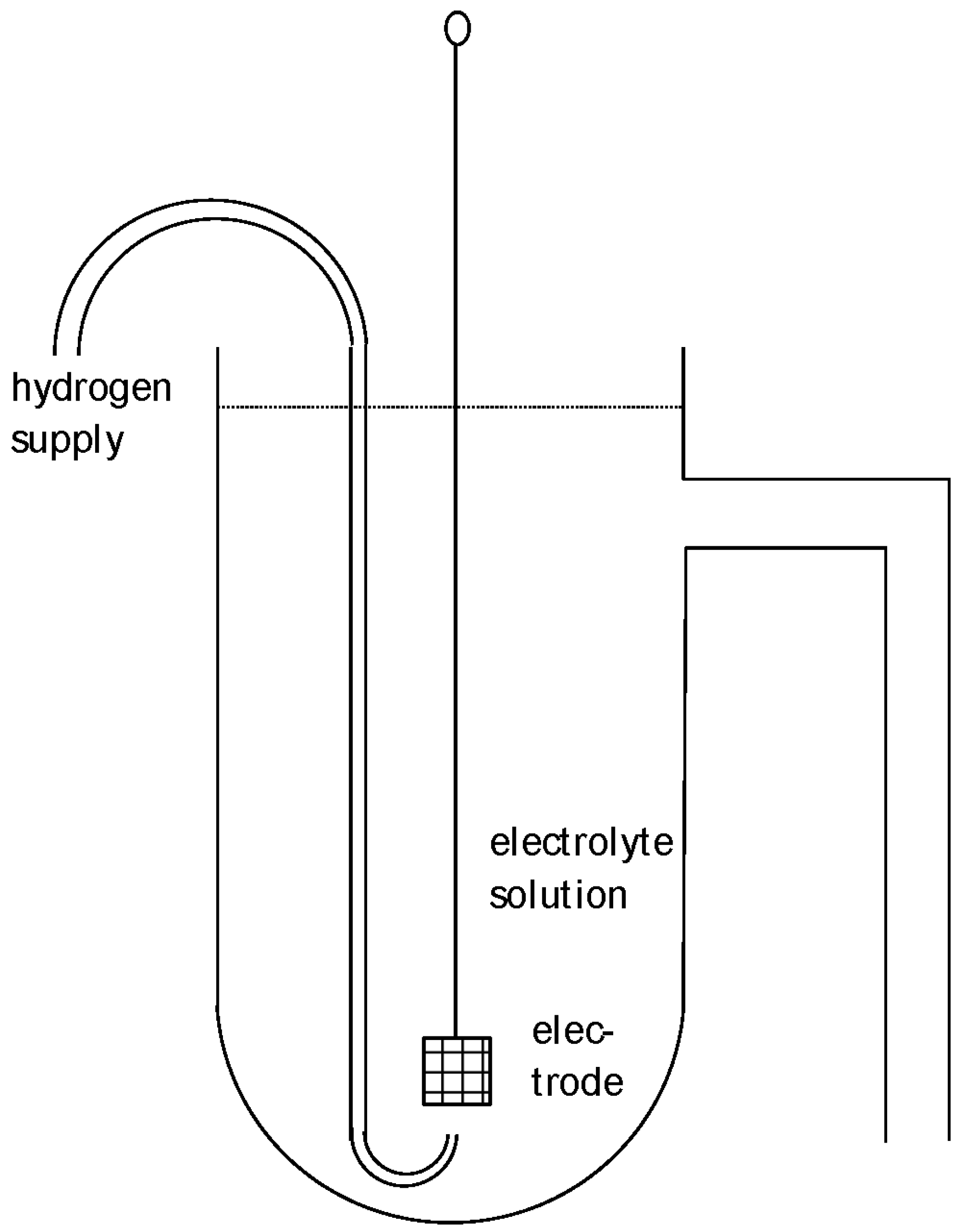
Measurement of a single electrode’s potential (or absolute potential) is not feasible, as has been discussed extensively in a vast body of literature conclusively reviewed in [5]; an update has been provided in [6]. An electric voltage U defined as the difference between two electrode potentials (in this text, the highly recommended but frequently ignored distinction between potential and voltage is maintained; the use of the same unit, which is possibly the cause of frequent confusions, is no contradiction) can nevertheless be measured (in units of voltage V) easily with high precision. The obtained results obviously do not enable the assignment of the electrode potentials to the electrodes used. To resolve this problem, one electrode potential under well-defined conditions has arbitrarily been defined as being zero at all temperatures. This electrode is the standard hydrogen electrode. In this electrode, as an electronically conducting phase, a piece of inert metal, most commonly platinized platinum, is brought into contact with an ionically conducting phase composed of an aqueous solution with a unit of proton activity saturated with hydrogen gas at a unit of pressure activity. The electrode’s reaction establishing the electrode is the hydrogen electrode’s reaction with a zero net current at equilibrium, i.e., hydrogen evolution and hydrogen oxidation proceed at the same rate:
H2 + 2 H2O ⇄ 2 H3O+ + 2 e−
This SHE is sometimes called the normal hydrogen electrode (NHE) as initially suggested 1898 by Nernst with a hydrogen pressure of 1 atm and 1 M sulfuric acid. Sometimes, it has been proposed that because the term refers to “normal” as obsolete concentration information, it should be avoided. The SHE is the primary standard for determining the electrode potential. A typical design is shown in Figure 1. Further electrodes combined with the SHE yield an electrochemical cell (combined of two half-cells) with two electric connectors enabling the measurement of voltage, specifically the cell’s voltage. The electric connectors of both terminals should be identical in order to avoid any electric contributions from metallic contacts. Measurement must be performed with zero current in order to avoid any shift in the electrode potentials; for details see, e.g., [7,8,9,10]. Because the electrode potential of the SHE has been set to zero, the measured cell voltage is equal to the electrode potential of the second electrode. The voltage of this cell may be called the cell potential because the numerical value is equivalent to the value of the electrode potential of the other electrode. This usage does not help; it only results in confusion and should be avoided.
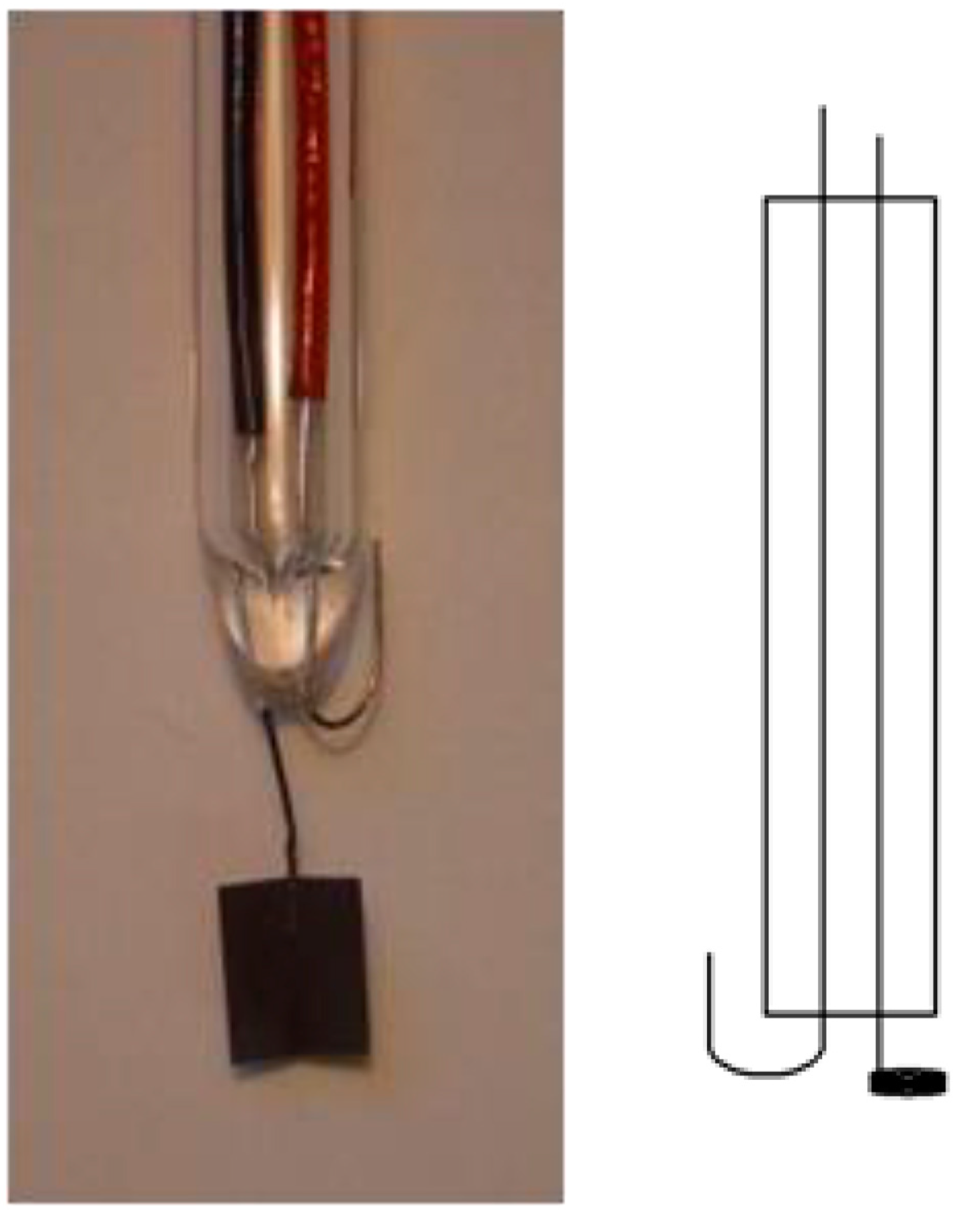
Because the use of a reference electrode needing a continuous supply of high-purity hydrogen gas is a rather unwelcome experimental detail in many applications [7,8,9,10,11,12], alternative options have been suggested. A setup initially suggested by Giner [13] (for further developments and simplification details, see [8,9]) is depicted below in Figure 2. This electrode has also been called a dynamic hydrogen reference electrode (DHRE).
At the large area of a platinized platinum electrode, hydrogen is formed by applying a small electric current supplied by an external power source [8], with the wire electrode serving as an oxygen-developing electrode. Because the current density j0 at the hydrogen electrode is negligibly small, its electrode potential hardly deviates from the other potential. Thus the electrode potential of hydrogen depending only on the proton activity in the surrounding electrolyte solution is controlled. Accordingly, the electrode is called a relative hydrogen electrode RHE (with an electrode potential relative to the proton activity). The pressure activity of hydrogen depends on the surrounding pressure; in most cases, it will be unity. Frequently, RHE is spelled out as “reversible hydrogen electrode”. This does not make sense for two obvious reasons: To be useful as a reference electrode, it must be reversible (in whatever meaning of this term); in addition, this term lacks information about the pH dependence of this electrode. Nevertheless, even a plain hydrogen electrode is sometimes called a reversible hydrogen electrode—an obvious pleonasm [14]. This report is also noteworthy because it describes the technology of hydrogen electrodes from before 1964 as desirable laboratory equipment.
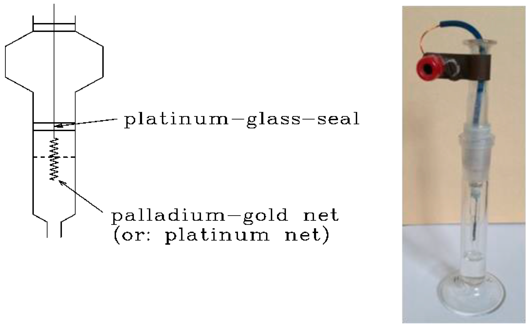
The need for an external power supply with the Giner electrode (even only a single D-size alkaline cell with a simple Ohmic resistor of 15 kΩ [8]) has stimulated further developments, resulting in the self-contained reference electrode described first by Will [15,16]. A schematic cross-section and a typical sample are shown in Figure 3. The hydrogen gas is formed by the electrolyte solution already present in the glass tube and the metal wick inside as the cathode, with an external second electrode as the anode. Hydrogen is formed, the gas bubble establishes a pressure activity of unity, whereas the proton activity controls the electrode potential of the RHE. This electrode has sometimes been called a convenient hydrogen electrode (CHE). Depending on the glass-to-metal seal atop the gas bubble (e.g., its sealing quality), the gas bubble may stay in place for many weeks. With proper storage preventing the access of dioxygen, the electrode is ready for use for the said period of time.
A general drawback of RHEs is noteworthy. The actual exchange current density of the hydrogen electrode’s reaction established at the electrode depends on the proton activity. In the range between strongly acidic and alkaline values, it drops to low values [17,18]. Thus, a fundamental requirement for reference electrodes is the following. If a large exchange current density keeping the electrode unpolarized (or non-polarizable) vanishes to some extent, the hydrogen electrode potential may become instable. Accordingly, all types of hydrogen electrodes should preferably be used in strongly acidic or alkaline solutions. In other solutions, they may be used (because of their major advantage: they do not introduce any other ionic species into the electrolyte solution) only with frequent calibration.
Certainly, the hydrogen electrode as depicted in Figure 1 suffers from inherent practical limitations, whereas the latter designs described above are more or less convenient to handle with associated major advantages. Accordingly, the claim reported elsewhere [19] that the standard hydrogen electrode has lost its practical importance should be limited—if assumed to be valid at all—to the electrode shown in Figure 1. The other hydrogen electrodes (RHEs) enjoy considerable popularity because of their obvious advantages.
Nevertheless, there remain circumstances (neutral electrolyte solutions, long-term unattended use etc.) requiring other reference electrodes beyond SHEs and RHEs. They are secondary references; they will be presented in the following section.
2. Beyond the Hydrogen Electrode: Practical Realizations
An electrode must meet some requirements for practical use as a reference electrode. This does not exclude the electrodes not mentioned below from being used as a reference; the literature is full of such applications. However, these examples, in most cases, have major limitations which exclude them from being presented below.
These requirements are as follows:
- The charge transfer reaction must proceed quickly and reversibly, i.e., with a large exchange current density j0. Although a reference electrode should operate at zero current, by mistake, a small current might flow sometimes, even only temporarily. With large values of j0, equilibrium and the correct resting potential are quickly attained again, and any deviations are minimal (non-polarizable electrodes).
- The electrode potential must be stable over time.
- The electrode potential should be independent from temperature changes.
- The electrode should be of a low-impedance design, and any obstructions to the free movement of ions providing the ionic connection between the reference electrode and the working electrode under study should be avoided.
Although systems sometimes do not meet all these requirements under all conditions, some of them are very close to this.
Many metal–metal ion electrodes meet these requirements; they are called electrodes of the first kind [20]. The electrode reaction of a typical electrode with a preferable one-electron transfer suitable as a reference is the silver–silver ion electrode
Ag ⇄ Ag+ + e−
The electrode potential is given by the Nernst equation
containing the number of electrons transferred (equal to 1, the usage of the variable n or z seems to be variable in the literature, see e.g., [3,6], with the latter usage observed correctly here), the activities are those of silver ions and of metallic silver. The latter is equal to one because silver is present as an element. Accordingly, Equation (4) can be simplified into
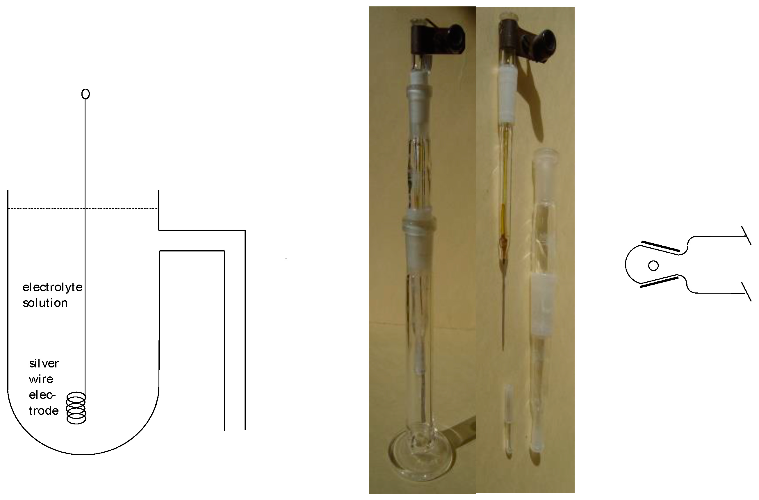
A schematic sketch and typical practical forms are shown in Figure 4. In order to minimize the exchange of the liquid (electrolyte solution) inside the reference electrode, in the subsequent experimental setup, various forms of liquid junctions establishing an ionically conducting connection have been developed. A ground glass sleeve diaphragm is shown schematically in Figure 4; further options have been described elsewhere [2,6].
Because, in practical applications, determination of the silver ions’ activity may be inconvenient, the concentrations of silver are used and reported. This system is also used frequently with organic electrolyte solutions, wherein the ferrocene–ferrocenium redox system (see below) is a popular point of reference. Thus, the experimental data measured with the silver–silver ion reference electrode are converted to the ferrocene–ferrocenium scale by running a CV with the latter redox system in solution and an inert metal wire as the working electrode [7,21].
In practical applications, the preparation of a reference electrode of the first kind is still somewhat inconvenient because the correct concentrations need to be established by weighing the salts. Systems where the concentrations/activities are established by, for example, a solubility equilibrium are preferred. These so-called electrodes of the second kind [17] are the most popular secondary reference electrodes.
In a silver–silver chloride electrode, the electrode reaction is
Ag + Cl− ⇄ AgCl + e−
A silver wire coated with silver chloride (easily deposited by keeping the silver wire at a sufficiently high electrode potential in a chloride-containing electrolyte solution) is placed in contact with an electrolyte solution containing chloride ions with well-defined activity (or a more convenient concentration). A schematic design is shown in Figure 5.
The chloride activity is fixed by adding specific chloride concentrations (e.g., 0.1 M, 1 M or saturated KCl). The electrode potential is, accordingly,
Typical electrode potential values for SHEs are listed in Table 1.
The diaphragm (a porous ceramic or a porous glass plug, a wick of thin platinum wires or a wetted ground glass stopper (or sleeve) placed exactly into an opening of the reference electrode vessel) keeps the electrolyte solutions inside and outside separate, thus prohibiting excessive mixing. Because they also provide the pathways of ion movement needed to establish an electrolytic connection, they are a potential source of contaminations moving in possibly both directions. The rates of leakage of the electrolyte solution across the diaphragm depend strongly on the effective pressure difference and the type of diaphragm. They range from fractions of a milliliter to a few milliliters per day. Differences in the composition of electrolyte solutions inside and outside of the reference electrode, possibly involving ions with different mobilities, may result in the diffusion potential drop across the diaphragm, in the range of fractions of a millivolt up to a few millivolts [2,16]. In precision measurements, this must be taken into account [1].
Another construction with a large surface area of AgCl-coated silver particles providing a large surface area of AgCl particles that is effective in establishing the equilibrium of solubility is depicted in Figure 6. This design avoids a diaphragm and its associated problems, but the much easier exchange of solutions may result in more chloride entering the working electrode’s compartment, and/or components of the latter compartment contacting the silver and the silver halide particles, with potential contamination effects. To reduce the exchange of the electrolyte solutions, the large opening depicted in Figure 6 can be replaced by a very tiny pore-like opening. The reduced flow of the solution comes with increased electrolyte resistance, increasing the risk of electric interference.
The assembly of such reference electrode requires weighing of the halides and preparation of their solutions with exact concentrations. Saturated solutions are prepared simply by adding an excess amount of halide (most frequently KCl) to the solvent. The solubility of the halide thus determines the chloride’s concentration/activity. This unfortunately enhances an unwelcome property of this reference electrode: large concentrations of chloride are present; they may contaminate the electrolyte solutions of the investigated electrodes (working electrodes). Because chloride ions tend to adsorb strongly on many, mostly metallic, surfaces and either influence the electrode’s reactions or accelerate corrosion, chlorides are not welcome. If possible, an RHE without chloride ions may be an option. Another one is the use of one of the chloride-free reference electrodes of the second kind as described below.
In a neutral sulfate-containing electrolyte solution, mercury may show a one-electron transfer electrode reaction
with the electrode potential according to the Nernst equation
This mercury–mercurous sulfate reference electrode has the considerable advantage of being free of chloride ions. Most frequently, a sulfate concentration controlling the activity of mercurous ions by the equilibrium of solubility is either established by using solutions saturated with K2SO4 or a defined concentration of sulfuric acid or K2SO4. When low sulfate concentrations are used, the electrode potential should be checked frequently. A schematic design is shown in Figure 7.
In alkaline electrolyte solutions, the movement of hydroxide ions into the reference electrode may cause unwelcome reactions of the constituents inside (e.g., the decomposition of calomel). For alkaline electrolyte solutions, the mercuric oxide reference is a more suitable option. The potential-controlling reaction is
Hg + 2 OH− ⇄ HgO + 2 e− + H2O
The electrode potential depends on the activity of the hydroxyl ions, which, in turn, controls the activity of the Hg2+-ions:
Their construction is similar to the one shown above in Figure 7, with mercury(II) oxide instead of Hg2SO4. Because strongly alkaline solutions may attack the glass used, the construction materials should be selected accordingly.
Possibly, the most frequently used reference electrode is the calomel electrode [22]. The compound Hg2Cl2 determining the concentration of Hg+-ions derives its name from Greek (“kalos” meaning “beautiful” and “melos” meaning “black”) because it can disproportionately yield finely dispersed metallic mercury, which appears black. The electrode reaction is
2 Hg + 2 Cl− ⇄ Hg2Cl2 + 2 e−
The activity of chloride ions controls the electrode potential according to
For practical reasons, the concentrations are commonly specified. Some typical potential values of the electrodes filled with solutions of the most frequently used concentrations of KCl are listed in Table 2. KCl is generally preferred because the similar ionic mobilities of chloride and potassium ions result in very small diffusion potentials. In some experimental settings, potassium ions are not acceptable, and thus sodium chloride is substituted.
The solubility of calomel, and particularly of KCl, depends significantly on the temperature. Accordingly, the potential of the saturated calomel electrode also depends on the temperature. An equation describing this relationship has been reported for a 1 M KCl concentration [23]:
E [Vint.] = 0.2801 − 2.75 × 10⁻⁵(T − 25 °C) − 2.5 × 10⁻⁶(T − 25 °C)2 − 4 × 10⁻⁹(T − 25 °C)
A schematic design is shown in Figure 8.
At T > 80 °C, calomel decomposes. The reaction starts at around 35 °C according to
Hg2Cl2 ⇄ Hg + HgCl2
For a thallium amalgam (40%) combined with thallium chloride, a reference electrode that is stable up to 135 °C can be prepared.
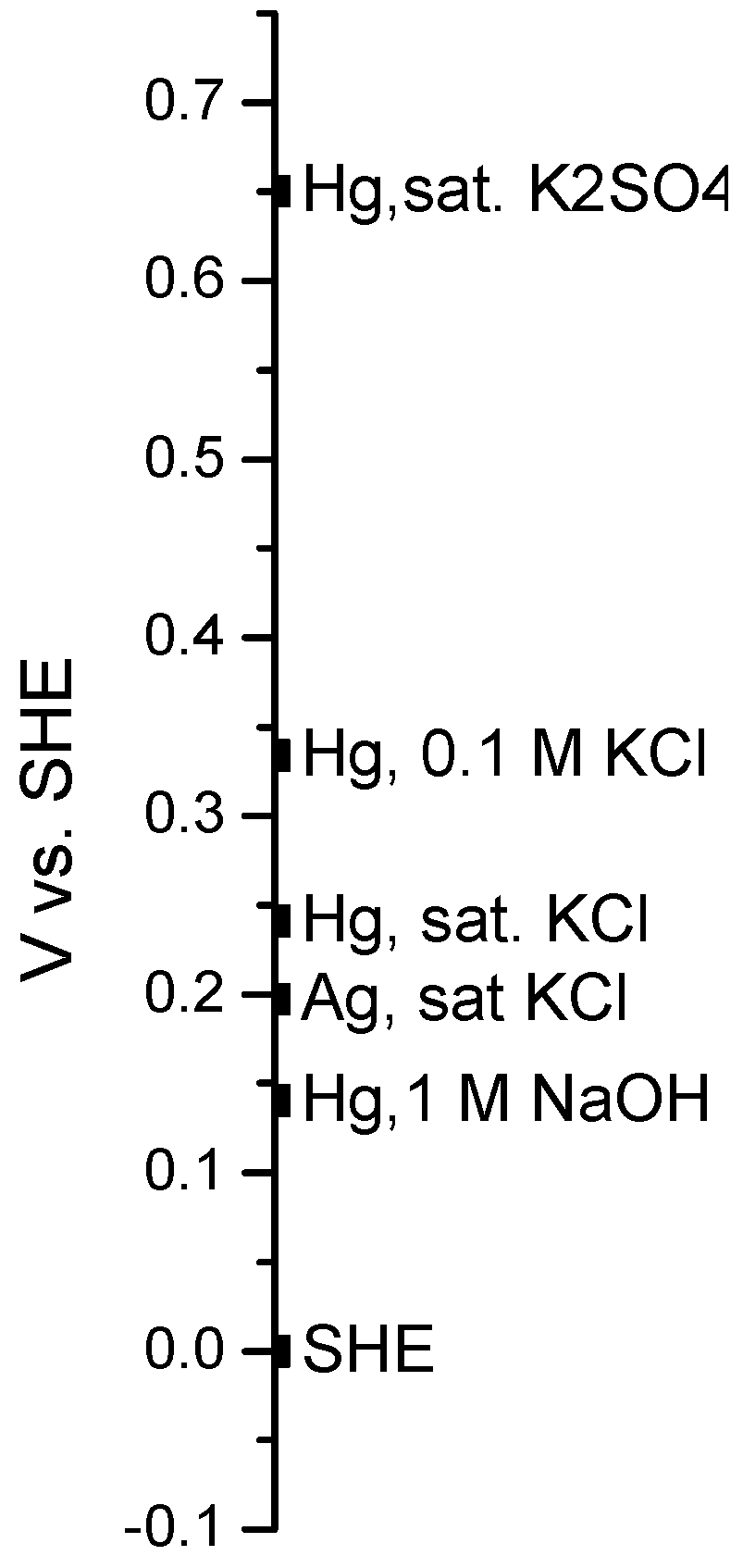
The electrode potentials of selected reference electrodes can be displayed conveniently with respect to that of the SHE as shown below in Figure 9.
Electrodes of the third kind, which have two sparingly soluble solids instead of one (see above), have been reported [17]. A typical example is metallic zinc in contact with a solution containing calcium ions and saturated with zinc oxalate and calcium oxalate. The electrode potential is given by the Nernst equation according to:
The activity of zinc ions is controlled by the activity of oxalate and the solubility constant KZnOx according to
The activity of oxalate ions is
This combination yields:
Obviously, this electrode is useful for determining the activities of calcium ions, its use as a reference electrode has not been reported.
Further reference electrodes, mostly utilizing the concept of the electrodes of the second kind with, for example, silver and silver bromide or silver iodide or silver sulfide, have been described.
A quasi-reference or pseudo-reference electrode (the terms appear to be synonymous) is an electrode composed in the simplest case of a metal wire (e.g., an AgCl-coated silver wire) immersed into the studied electrolyte solution, which establishes an electrode potential that is sufficiently stable within the timeframe of the experiment without matching the requirements for a reference electrode listed above. Because this potential cannot be calculated (the Nernst equation does not apply), the potential of this pseudo-reference must be checked versus another real reference electrode. In this check, care must be taken to keep the pseudo-reference electrode in its electrolyte solution.
3. Practical Hints
Reference electrodes should be stored in suitable electrolyte solutions when not in use. In the case of the secondary electrodes presented above, the storage solution should be the same as the solution inside the electrode, but there is no need to add the barely soluble metal salts needed to establish the electrode potential (e.g., AgCl, Hg2Cl2). Hydrogen electrodes should be kept in the solution used inside them (electrodes according to Will) or in pure water (all others). Drying may cause damage to the platinized electrode.
From time to time, the electrode potential should be measured against either a primary reference electrode or against another reference electrode stored under carefully controlled conditions and used only for this purpose. Whether deviations of 1 to 2 mV are a sufficient reason to take the reference electrode apart, clean all the components and reassemble the reference electrode depends on the required precision of the studied system. In reference electrodes with a porous diaphragm, this may cause deviations when the diaphragm is clogged by deposits or contaminated otherwise, and extensive soaking in water or suitable solutions may help. Use of a ground glass diaphragm instead may sometimes be preferable because it can be taken apart and cleaned easily. Another option that is suitable for establishing a liquid junction enabling electrolytic connection is the use of a small hole (pore) or capillary. Given the advantages of this approach, experimental setups providing a simplified method of establishing a controlled small flow of liquid have been developed [28].
4. Trends and Developments
Two trends stimulated by the technological developments and ever-increasing applications are particularly noteworthy: miniaturization and solid-state electrodes. Numerous reference electrodes are combined with working electrodes operating as ion-sensitive and/or ion-selective electrodes. In many cases, the electrochemical cell obtained by this combination of two half-cells should operate in environments requiring a size as small as possible (e.g., biomedical applications). Some of the designs sketched above can be miniaturized straightforwardly.
This development is matched by the progress of all solid-state reference systems [29,30]. Except for mercury in most of the mercury-based systems described above, the only liquid component in the reference electrodes is the electrolyte solution. Liquid electrolyte solutions may leak from the reference electrode into the electrochemical cell and leakage into the environment, particularly when the electrode has been mechanically damaged. In addition, liquid components interfere with miniaturization. Gelled, polymeric or solid electrolytes are frequently applied. A common concept starts with a silver wire or a silver dot on an inert substrate, which also provides the electrical connection. A coating of AgCl is applied. A further coating of AgCl mixed with KCl and a polymeric binder (e.g., polyvinylchloride) functions as a solid electrolyte. A final polymer coating with a tiny hole instead of a diaphragm provides a connection to the environment.
The growing importance of ionic liquids has increased interest in reference electrodes that are compatible with these electrolytes; recent developments have been discussed [31,32].
Further trends deal with the use of materials causing environmental concerns. Accordingly, the use of mercury is avoided when possible.
5. Conclusions
Currently, the already large number of available reference electrodes that cover a wide range of sizes and are suitable for many different operating conditions will grow further, given the increasing impact of electrochemical methods in devices and processes almost everywhere. Based on a well-established range of operating principles, new material, production processes and practical challenges will result in new models meeting the ever more demanding challenges of application.
Funding
Financial support was provided through the research projects at St. Petersburg State University (grant Nos. 26455158 and 70037840) is appreciated. Preparation of this entry has been supported in various ways by the Alexander von Humboldt Foundation, Deutscher Akademischer Austauschdienst, Fonds der Chemischen Industrie, Deutsche Forschungsgemeinschaft, National Basic Research Program of China and the Natural Science Foundation of China.
Institutional Review Board Statement
Not applicable.
Informed Consent Statement
Not applicable.
Data Availability Statement
Not applicable.
Conflicts of Interest
The authors declare no conflict of interest.
References
- Holze, R. Landolt-Börnstein, Numerical Data and Functional Relationships in Science and Technology, New Series, Group IV: Physical Chemistry, Electrochemistry, Subvolume A, Electrochemical Thermodynamics and Kinetics; Martienssen, W., Lechner, M.D., Eds.; Springer: Berlin/Heidelberg, Germany, 2007; Volume 9. [Google Scholar]
- Bard, A.J.; Inzelt, G.; Scholz, F. (Eds.) Electrochemical Dictionary; Springer: Berlin/Heidelberg, Germany, 2012. [Google Scholar]
- Quack, M.; Stohner, J.; Strauss, H.L.; Takami, M.; Thor, A.J.; Cohen, E.R.; Cvitas, T.; Fry, J.; Holström, B.; Kuchitsu, K.; et al. (Eds.) Quantities, Units and Symbols in Physical Chemistry; RSC: Cambridge, UK, 2007. [Google Scholar]
- Wu, Y.; Holze, R. Electrochemical Energy Conversion and Storage; Wiley-VCH: Weinheim, Germany, 2022. [Google Scholar]
- Trasatti, S. The “absolute” electrode potential-the end of the story. Electrochim. Acta 1990, 35, 269–271. [Google Scholar] [CrossRef]
- Inzelt, G.; Lewenstam, A.; Scholz, F. (Eds.) Handbook of Reference Electrodes; Springer: Berlin/Heidelberg, Germany, 2013. [Google Scholar]
- Holze, R. Experimental Electrochemistry: A Laboratory Textbook, 2nd ed.; VCH-Wiley: Weinheim, Germany, 2019. [Google Scholar]
- Caton, R.D., Jr. Topics in chemical instrumentation: LXXIII. Reference electrodes. J. Chem. Educ. 1973, 50, A571–A578. [Google Scholar] [CrossRef]
- Pletcher, D. A First Course in Electrode Processes, 2nd ed.; The Royal Society of Chemistry: Cambridge, UK, 2009. [Google Scholar]
- Bard, A.J.; Faulkner, L.R. Electrochemical Methods, 2nd ed.; Wiley: New York, NY, USA, 2001. [Google Scholar]
- Holze, R. Eine einfache Wasserstoffbezugselektrode. CHEMKON 2003, 10, 87–88. [Google Scholar] [CrossRef]
- Roscher, J.; Holze, R. Messungen mit Wasserstoffelektroden ohne Druckgas—Measurements with a hydrogen electrode without pressured gas. CHEMKON 2022, 29, 408–411. [Google Scholar] [CrossRef]
- Giner, J. A practical reference electrode. J. Electrochem. Soc. 1964, 111, 376–377. [Google Scholar] [CrossRef]
- Zamora Zeledón, J.A.; Jackson, A.; Stevens, M.B.; Kamat, G.A.; Jaramillo, T.F. Methods—A Practical Approach to the Reversible Hydrogen Electrode Scale. J. Electrochem. Soc. 2022, 169, 066505. [Google Scholar] [CrossRef]
- Will, F.G.; Hess, H.J. Morphology and Capacity of a Cadmium Electrode. J. Electrochem. Soc. 1973, 120, 1–11. [Google Scholar] [CrossRef]
- Will, F.G. A self-contained miniature hydrogen reference electrode. J. Electrochem. Soc. 1986, 133, 454–455. [Google Scholar] [CrossRef]
- Vielstich, W. Brennstoffelemente; Verlag Chemie: Weinheim, Germany, 1965. [Google Scholar]
- Ernst, S.; Hamann, C.H. The pH-dependence of the hydrogen exchange current density at smooth platinum in alkaline solution (KOH). J. Electroanal. Chem. 1975, 60, 97–100. [Google Scholar] [CrossRef]
- Kahlert, H. Reference electrodes. In Electroanalytical Methods; Scholz, F., Ed.; Springer: Berlin/Heidelberg, Germany, 2010; pp. 291–308. [Google Scholar]
- Kortüm, G. Lehrbuch der Elektrochemie, 5th ed.; Verlag Chemie: Weinheim, Germany, 1972. [Google Scholar]
- Holze, R. Electrode Potentials: Conversion Scales and Calculations. In Comprehensive Coordination Chemistry III Vol. 2; Elsevier: Amsterdam, The Netherlands, 2021; pp. 119–128. [Google Scholar]
- Ives, D.J.G.; Janz, G.J. Reference Electrodes; Academic Press: New York, NY, USA, 1961. [Google Scholar]
- Chateau, H. Déterminations précises des potentiels de référence données par les électrodes au calomel entre 5 et 70 °C. J. Chim. Phys. 1954, 51, 590–593. [Google Scholar] [CrossRef]
- Honold, F.; Honold, B. Ionenselektive Elektroden; Birkhäuser Verlag: Basel, Switzerland, 1991. [Google Scholar]
- Oehme, F. Ionenselektive Elektroden; Huethig Buch Verlag: Heidelberg, Germany, 1991. [Google Scholar]
- Zoski, C.G. (Ed.) Handbook of Electrochemistry; Elsevier: Amsterdam, The Netherlands, 2007. [Google Scholar]
- Alnoush, W.; Black, R.; Higgins, D. Judicious selection, validation, and use of reference electrodes for in situ and operando electrocatalysis studies. Chem. Catal. 2021, 1, 997–1013. [Google Scholar] [CrossRef]
- Anderson, E.L.; Troudt, K.; Bühlmann, P.B. Easy-to-Make Capillary-Based Reference Electrodes with Controlled, Pressure-Driven Electrolyte Flow. ACS Sens. 2021, 6, 2211–2217. [Google Scholar] [CrossRef] [PubMed]
- Guth, U.; Gerlach, F.; Decker, M.; Oelßner, W.; Vonau, W. Solid-state reference electrodes for potentiometric sensors. J. Solid State Electr. 2009, 13, 27–39. [Google Scholar] [CrossRef]
- Gellings, P.J.; Bouwmeester, H.J.M. (Eds.) The CRC Handbook of Solid State Electrochemistry; CRC: Boca Raton, FL, USA, 1997. [Google Scholar]
- Lindner, E.; Guzinski, M.; Khan, T.A.; Pendley, B.D. Reference Electrodes with Ionic Liquid Salt Bridge: When Will These Innovative Novel Reference Electrodes Gain Broad Acceptance? ACS Sens. 2019, 4, 549–561. [Google Scholar] [CrossRef] [PubMed]
- Frenzel, N.; Hartley, J.; Frisch, G. Voltammetric and spectroscopic study of ferrocene and hexacyanoferrate and the suitability of their redox couples as internal standards in ionic liquids. Phys. Chem. Chem. Phys. 2017, 19, 28841–28852. [Google Scholar] [CrossRef] [PubMed] [Green Version]
Figure 1.
Schematic design of a hydrogen reference electrode.

Figure 2.
Schematic cross-section (right) and typical sample of a hydrogen electrode according to Giner.
Figure 2.
Schematic cross-section (right) and typical sample of a hydrogen electrode according to Giner.

Figure 3.
Schematic cross-section (left) and practical sample of an RHE according to Will.

Figure 4.
Schematic design of a silver–silver ion reference electrode (left). Practical form assembled and disassembled (middle), not yet filled with the electrolyte solution, and with a stopper/sleeve diaphragm. (Right) Another form of ground glass sleeve diaphragm.
Figure 4.
Schematic design of a silver–silver ion reference electrode (left). Practical form assembled and disassembled (middle), not yet filled with the electrolyte solution, and with a stopper/sleeve diaphragm. (Right) Another form of ground glass sleeve diaphragm.

Figure 5.
Schematic cross-section of a simple Ag–AgCl-reference electrode.

Figure 6.
Schematic cross-section and photograph of a Ag–AgCl-reference electrode.

Figure 7.
Schematic cross-section of a simple mercury–mercurous sulfate reference electrode (left), its components (middle) and the assembled device (right).
Figure 7.
Schematic cross-section of a simple mercury–mercurous sulfate reference electrode (left), its components (middle) and the assembled device (right).

Figure 8.
Schematic cross-section of a simple calomel reference electrode (left) and the assembled example (right).
Figure 8.
Schematic cross-section of a simple calomel reference electrode (left) and the assembled example (right).

Figure 9.
Selected reference electrode potentials with respect to that of the SHE.


Table 1.
Electrode potentials for a standard hydrogen electrode of various silver/silver chloride electrodes.
Table 1.
Electrode potentials for a standard hydrogen electrode of various silver/silver chloride electrodes.
| Aqueous Solution | ESHE/V |
|---|---|
| Saturated with KCl | 0.197 |
| 1 M KCl | 0.236 |
| 0.1 M KCl | 0.289 |
| 0.222 |
Table 2.
Electrode potentials for the standard hydrogen electrode of calomel electrodes at T = 25 °C with various chloride concentrations [19].
Table 2.
Electrode potentials for the standard hydrogen electrode of calomel electrodes at T = 25 °C with various chloride concentrations [19].
| Aqueous Solution | ESHE/V |
|---|---|
| Saturated with KCl | 0.2444 |
| 3.5 M KCl | 0.2466 at T = 40 °C |
| 1 M KCl | 0.2801 |
| 0.1 M KCl | 0.3337 |
Disclaimer/Publisher’s Note: The statements, opinions and data contained in all publications are solely those of the individual author(s) and contributor(s) and not of MDPI and/or the editor(s). MDPI and/or the editor(s) disclaim responsibility for any injury to people or property resulting from any ideas, methods, instructions or products referred to in the content. |
© 2023 by the authors. Licensee MDPI, Basel, Switzerland. This article is an open access article distributed under the terms and conditions of the Creative Commons Attribution (CC BY) license (https://creativecommons.org/licenses/by/4.0/).
Share and Cite
MDPI and ACS Style
Roscher, J.; Holze, R. Reference Electrodes. Encyclopedia 2023, 3, 478-489. https://doi.org/10.3390/encyclopedia3020033
AMA Style
Roscher J, Holze R. Reference Electrodes. Encyclopedia. 2023; 3(2):478-489. https://doi.org/10.3390/encyclopedia3020033
Chicago/Turabian StyleRoscher, Jessica, and Rudolf Holze. 2023. "Reference Electrodes" Encyclopedia 3, no. 2: 478-489. https://doi.org/10.3390/encyclopedia3020033