1. Introduction
In recent years, power systems have been experiencing a rapid transformation due to the ever-increasing integration of Renewable Energy Sources (RES) and distributed generation [
1]. These resources allow for a significant reduction in the carbon footprint, but pose several challenges from the monitoring and control point of view. Based on natural phenomena beyond human control, RES are inherently volatile and hardly predictable. Moreover, RES are typically operated in Direct Current (DC) mode and require dedicated power converters to be interconnected to the rest of the grid [
2]. Such an interface relies on fast-switching power electronics that do not contribute to the overall system inertia [
3,
4] and inject spurious contributions in the harmonic and supraharmonic range [
5,
6]. It is thus reasonable to expect that the power signals are going to be subject to higher distortion rates and faster dynamics, making the system prone to sudden contingencies or even blackouts (as proven by the recent events in California [
7] or South Australia [
8]).
In order to address this challenge, the monitoring and control infrastructure shall rely on a suitable measurement system, characterized by remarkable performance in terms of both accuracy and latency [
9,
10]. In this sense, a promising solution is represented by Phasor Measurement Units (PMUs) that produce time-stamped measurements of voltage and current phasors, frequency and rate-of-change-of-frequency (ROCOF). The time-stamp is referred to a common and traceable time reference and thus allows to aggregate and compare synchronized measurements taken at different grid nodes [
11,
12].
Such a distributed measurement infrastructure can be realized by interconnecting different devices in different locations. A complete refurbishment of each grid substation is practically unfeasible and therefore one of the first challenges to solve is represented by the interoperability, i.e., the capability of interconnecting instruments from different manufacturers and with different specifications [
13]. In this sense, the IEC 61850 [
14] constitutes the framework for the development of a fully digital and inter-operable substation, where the different Intelligent Electronic Devices (IED) communicate with each other using the same protocols and data formats [
15,
16,
17]. In particular, the IEC 61850-9-2 introduces the Sampled Value (SV) protocol for the transmission of the secondary output of Non-Conventional Instrument Transformer (NCIT) [
18]. In the typical measurement setup, a Stand Alone Merging Unit converts the analog output of the NCIT into a digital stream of SV and publishes them on the substation network. In this way, the SV are available not only for storage and post-processing applications in the control room, but also for an on-line estimation process as performed by IEDs [
16], PMUs [
19,
20] or Power Quality Instruments (PQIs) [
21,
22]. The recent literature has proposed several approaches for calibration of NCIT [
23,
24] or related instrumentation [
25]. Furthermore, the synchronization aspects have been addressed [
26], but not so much attention has been given to the possible repercussions on real power systems’ operations.
In this regard, it is worth noticing that both the publisher (e.g., the SAMU) and the subscriber (e.g., the PMU) are disciplined to a common time reference with different synchronization requirements, as dictated by the corresponding reference standards. To this end, there exist several possible configurations. In a fully digital substation, it is reasonable to expect that both devices are connected to the same PTP clock and configured with the same profile (for instance, power or utility profile). If the SAMU supplies a complete time-stamp (as defined in IEC TR 61850-90-5 [
27]), the PMU can operate without the local clock input. Another possibility is to use the optional SV time-stamp field as defined in IEC 61850-9-2. Nevertheless, in this transition period, the possibility of independent time sources cannot be discarded a priori.
From a normative point of view, the recent IEC/IEEE Std 60255-118-1 [
28] includes the Annex E for synchrophasor measurements using SV inputs with specific performance requirements in terms of estimation accuracy and reporting latency. Following a conservative approach, the Annex proposes to consider the PMU measurements as invalid as soon as the SAMU looses its time reference. Nevertheless, the recent literature has proposed an alternative approach that would allow us to maintain the continuity of PMU service, yet flagging the measurements as less reliable [
20]. As defined in IEEE Std C37.118.2 [
29], the PMU measurement data packet contains a 32-bit field FRACSEC consisting of two components: a 24-bit unsigned integer for the fractional second, and an 8-bit message for the time quality flag. The latter accounts for the quality of the time information as well as the leap second status. In more detail, the time quality is expressed in seven classes, ranging from normal operation to clock failure. Each class is associated with a worst-case accuracy of the clock source, quantified in terms of deviation between the full second transition and the Coordinated Universal Time (UTC), e.g., the hexadecimal code 4 corresponds to a worst-case deviation of 1
s.
In this paper, we consider the case of a measurement chain where the SAMU and the PMU are disciplined by two independent clocks. On the SAMU side, the temporary loss of the GPS antenna causes the absence of the time reference. Even after the restoration of the antenna connection, it is likely to expect several minutes before the SAMU is actually locked to UTC. In the meantime, the SAMU keeps producing the SV stream, but the packets time-stamp is flagged as unreliable. On the PMU side, despite the device is still locked to UTC, the PMU time quality shall be updated to not be synchronized until the SAMU synchronization has been restored. As a consequence, a similar event may cause a service interruption lasting even tens of minutes [
30]. On the other hand, modern PMUs rely on clocks characterized by remarkable performance in terms of short-term stability and resolution in the order of sub-millisecond scale [
31,
32,
33]. Based on this consideration, this paper proposes a novel approach for a faster comeback to quasi-normal operating conditions. By suitably time-stamping the incoming SV packets, the PMU assesses the deviation of the SAMU full second transition from the UTC one. In this way, the PMU is able to update its time quality flag autonomously at each second. This solution does not guarantee the accuracy of the PMU measurements but provides a preliminary assessment of the measurement chain consistency. Instead of waiting the full restoration of the GPS signal, the control room can consider the PMU measurements and weights their reliability with a quantitative index.
The considered configuration has been reproduced in laboratory controlled conditions by implementing the SAMU and PMU functionalities in two industrial controllers with real-time clocks and operating systems. Extensive simulations have been performed to characterized the resolution and accuracy of the proposed method in both ideal and realistic conditions. The obtained results confirm the potential of the proposed approach and provides useful insights towards a more flexible and smart organization of digital substations. Indeed, we prove the possibility of autonomously update the PMU time quality in nearly 150 s, whereas waiting for the full restoration of the synchronization chain could cost several minutes. In this sense, the paper main novelty contribution shall be identified in the methodology of SV time-stamping and in the lightweight algorithm for time quality assessment.
The paper is organized as follows.
Section 2 introduces the measurement problem and the research motivation.
Section 3 provides some details about the implementation of the SAMU and PMU functionality within two industrial controllers and characterize the PMU capability of time-stamping the SV packets characterized by stationary (nominal and off-nominal) or time-varying publishing period.
Section 4 describes the measurement setup for the experimental validation.
Section 5 presents the proposed method and validates its performance in a real-world experiment. Finally,
Section 6 provides some closing remarks and outlines the future steps of the research activity.
2. Research Motivation
Modern substations are rapidly transitioning towards a fully digital and automated communication and control paradigm. The different IEDs installed in the substation do not operate independently and autonomously, but communicate with each other and with the control room in order to achieve a prompter and more efficient response to unexpected or even potentially dangerous events.
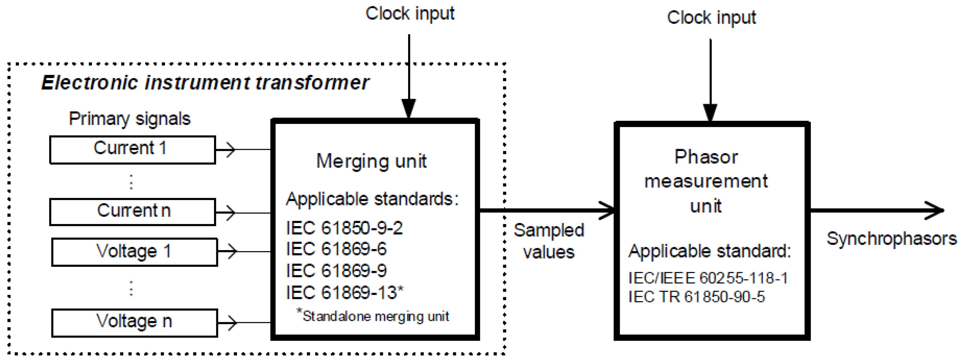
The IEC 61850 introduces the infrastructure and defines the message data types and performance requirements for the IED communications. In this regard,
Figure 1 presents the typical measurement chain. The power signals of interest are acquired via a suitable instrument transformer. A merging unit collects the digitized signals (e.g., three-phase voltage and current), and encloses them in a SV stream. The digital data stream is published over the substation network and made available to other measurement and control devices. For instance, a PMU may retrieve the SV stream and process it in order to produce the corresponding measurements of phasor, frequency and rate of change of frequency (ROCOF).
In the framework of IEC 61850, the communication relies on an Ethernet physical layer. It is thus reasonable to assume that also the synchronization signals could be transmitted over the same network, e.g., via a Precision Time Protocol (PTP). A single PTP clock, aligned to UTC via a GPS antenna, could provide an accurate and stable synchronization to all the IEDs installed in the substation, with a remarkable advantage in terms of cabling reduction and implementation costs. In order to address the challenging requirements typical of power system applications, a specific PTP profile is defined in the IEC 61850-9-3. The so-called Utility profile introduce stringent requirements for the grandmaster, transparent and boundary clocks. The objective is to guarantee an end-user timing accuracy not exceeding 1 s even in a network configuration consisting of 15 transparent clocks and/or 3 boundary clocks. In the same profile, a specific field clockClass accounts for the synchronization status and allows for discriminating between normal operations, loss and recovery of the synchronization. In particular, during the restoration after a synchronization loss, the clock status is progressively updated based on the expected time error: holdover, 1 s, 250 ns, recovered.
Indeed, it is important to underline that synchronization status has a crucial role for PMU measurements. Most PMUs use the external time-source signal not only to define the full second transition and thus the measurement time-stamp, but also to discipline the internal clock. As a consequence, an erroneous or a missing synchronization may affect not only the reporting time reference and thus the correct aggregation with other PMU measurements, but also the estimated quantities, particularly the phase angle and its derivatives (i.e., frequency and ROCOF).
In this regard, the IEC/IEEE Std 60255-118-1 defines a performance target for PMUs in normal operating conditions of a Total Vector Error (TVE) not larger than 1%. In the absence of magnitude errors, this corresponds to a phase angle error of 10 mrad. At a nominal system rate of 50 Hz, such a phase angle is equivalent to a timing error of nearly 32 s. This explains the importance of accurately determining the PMU time quality: values over 10 s could be associated with a measurement chain that is prone to large TVEs.
Based on these considerations, the configuration in
Figure 1 provides significant advantages. First of all, the adoption of a predefined and common data format guarantees a full-interoperability between any SAMU or PMU compliant with the pertinent standards. Moreover, the possibility of separate (and possibly independent) time sources for SAMUs and PMUs guarantees a redundant and effective control of the synchronization state of the two devices. In this regard, it is worth noticing that both SAMU and PMU packets include indicators of the synchronization status and quality of the respective device.
At the SAMU level, the synchronization signal triggers the publishing of the SV packet with packet count 0, that shall correspond to the full second transition. Each SV packet contains a SmpSync field that denotes the status of the merging unit synchronization. More precisely, the merging unit can be classified as synchronized or not. In the first case, the filed discriminates three clock categories: global area, local area and unspecified local area. The lower the quality of the clock, the higher the uncertainty propagated to the following elements in the measurement chain, i.e., the PMU.
In a PMU with digital inputs, the synchronization signal can be used to time-stamp the measurement data packets but also to check the consistency of the SV input stream (e.g., with a check on the SV packet latency). The PMU measurement data packets include several fields related to the synchronization status and quality. In the STAT field, the PMU Sync Error bit is set to 1 in the absence of a valid external time synchronization (e.g., loss of satellite tracking, time input connection failure or time source no more locked to UTC). In the FRACSEC field, instead, 32 bits are organized in two words. The first 24 bits represent the time elapsed since the last UTC full second. The last eight bits include the PMU Time Quality (PMU_TQ) flag. More precisely, three bits express the maximum time error with respect to UTC ranging in seven different levels from 100 ns to 10 ms. Finally, another two bits are used to quantify the Unlock Time, i.e., the count of seconds elapsed since the last loss of synchronization was detected.
Based on all these information, it is possible to accurately track the synchronization status of the entire measurement chain and promptly detect any fault or service interruption. In this sense, it is worth noticing that the PMU Std adopts a quite conservative approach. In the presence of a synchronization loss, the PMU measurements are flagged as unreliable until the synchronization source has returned to normal steady-state operations. In a hierarchical perspective, it is necessary that the PTP clock first, and the SAMU second, restore their time source integrity before the PMU can resume its normal operation. In GPS-based systems, this may take up to few tens of minutes, causing significant restrictions in many grid services as state estimation, fault location and power flow control.
On the other hand, modern PMUs rely on high-performing industrial controllers, typically equipped with real-time operating systems. In most cases, the internal clock is characterized by remarkable performances in terms of short-term stability and time-stamp accuracy. In this paper, we propose an alternative approach for the definition and update of the PMU Time Quality that would allow to reduce the time needed to come back to sufficient accuracy levels and thus restart crucial PMU-based grid applications. After the loss of synchronization, the PMU evaluates the received SV packets based on its internal clock. In this way, the PMU can check the consistency of the SV publishing period and verify the time deviation between the expected full second transition and the arrival time of the SV with count index equal to zero. This value can be considered as a rough estimation of the deviation of the SAMU clock with respect to UTC. By properly tracking the oscillations of this value, it is possible to update accordingly the PMU_TQ flag. Even if this is neither an accurate nor a traceable measurement method, with a sufficient confidence interval it is possible to restart the PMU operation when the time quality comes back within 10 µs. The overall accuracy would be sub-optimal, but anyway preferable than a complete absence of information.
3. SV Time-Stamping Functionality
This Section describes a possible implementation of SV time-stamping functionality within a PMU with digital inputs. In view of a full observability and controllability of the different synchronization and processing stages, in this paper we do not employ commercial SAMUs or PMUs. Conversely, the SAMU and the PMU functionalities are implemented in two industrial controllers, namely a NI cRIO-9040 and a NI cRIO-9068 (National Instruments, Austin, TX, USA). Further details about the realization and characteristics of the PMU based on digital inputs (briefly, SV-PMU) are available in [
20]. Each controller is equipped with high-performance processing units running Linux Real-Time (RT) operating systems, and a GPS receiver for locking their internal clock to UTC. By means of a point-to-point connection, the SV packets output by the SAMU are directly transmitted to the PMU. In this sense, the delay introduced by the two Ethernet adapters and the cable can be considered negligible.
From a programming point of view, the NI cRIO-9040 replicates the main functionalities of a SAMU. As soon a new full second transition is detected, the reference SAMU starts its SV data stream with a publishing period that can be either stationary or time-varying. At this stage of the research, the SV publishing period can be defined with a quantization level of 1 s, but a finer resolution would be possible by exploiting the FPGA board of the same controller. In a similar way, the NI cRIO-9068 includes a packet sniffer functionality that allows for capturing and decoding only the SV packets of interest. Each packet is time-stamped according to the internal time base and the time difference between consecutive packets is computed.
In this Section, the sensitivity of the SV-PMU clock oscillator through two different measurement approaches is considered. The first method consists of time-stamping a SV stream published with a stable and constant publishing rate, which reproduces the normal operation of a synchronized SAMU. The second method, instead, evaluates the time-stamping functionality when the SV stream is sent with a non-constant publishing period between packets. This condition may occur for example if there are: synchronization losses in the reference time system, internal malfunctions of the publisher or some troubles in the communication system.
In order to characterize the time-stamping performance with constant SV publishing periods, we apply the following calibration procedure. The SAMU encodes and sends out a series of SV packets, using the features of specific functions included within an ad hoc Shared Object library. This library is an extended version of the one presented in [
20] with additionally functionalities dedicated to the publishing of SV packets in real-time. In this context, the function designed to send the packets out of the Ethernet adapter is called once for each SV within the run of a timed loop. The execution frequency of such a loop is regulated by the
internal clock. In this regard, it is worth mentioning that the FPGA Timekeeper library of the cRIO-9040 guarantees a lock to UTC within 100 ns. By properly programming the IED, we can control the SV publishing process guaranteeing a sufficiently accurate and stable publishing period (typically in the order of hundreds microseconds).
On the receiver side, each packet subscribed by the SV-PMU is time-stamped. In order to determine the publishing period of the packet stream, the difference between current and previous SV time-stamp is calculated each time.
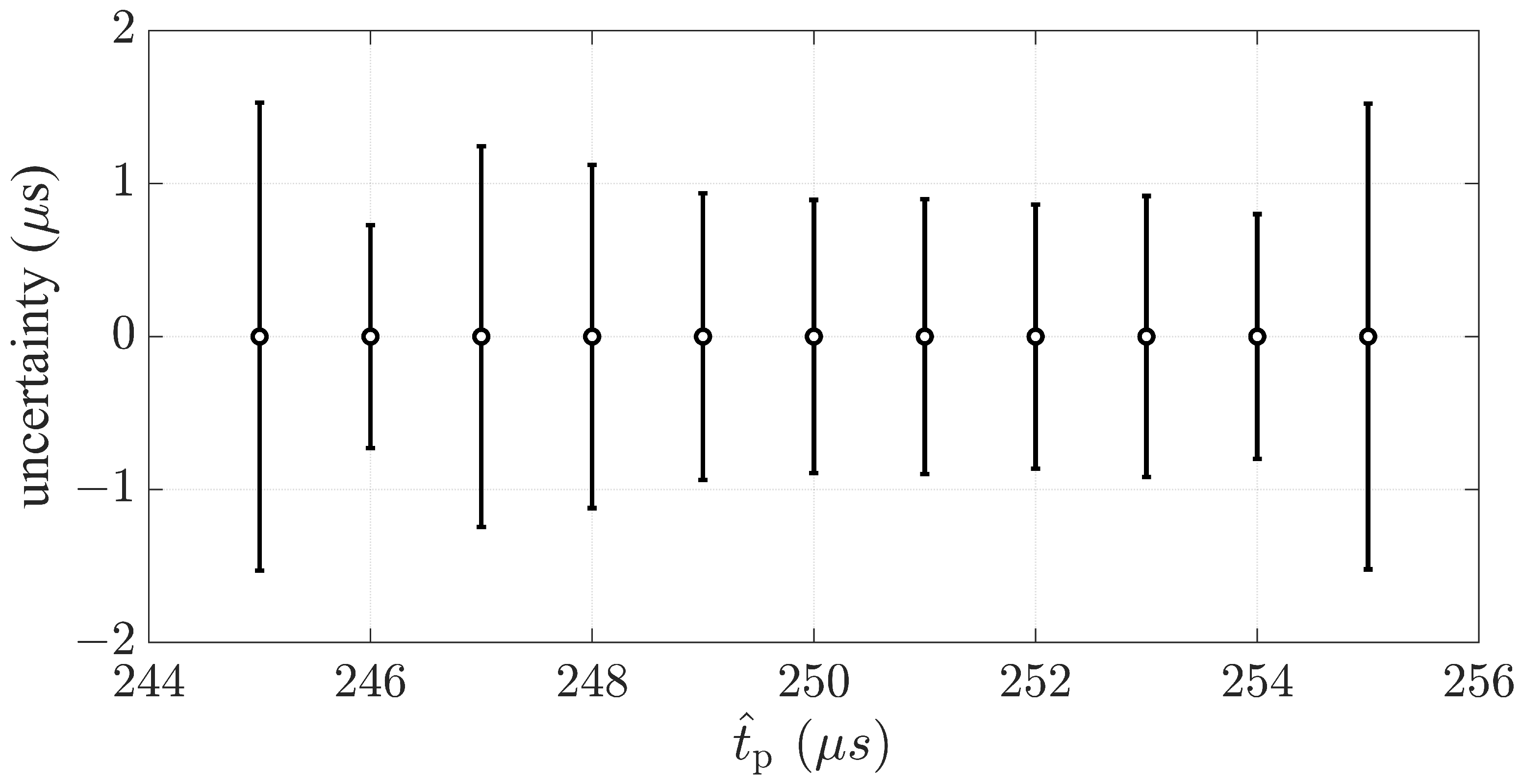
Figure 2 shows the symmetric uncertainties affecting the time periods elapsing between the SV packets as measured by the SV-PMU. Each of these uncertainties corresponds to two standard deviations determined from the values, computed by taking the difference between
time-stamped SV packets, normally distributed around the corresponding nominal publishing period
. For this uncertainty evaluation, eleven nominal publishing periods have been chosen within the interval ranging between 245 and 255
s, whose limits represent a 5
s deviation from 250
s, which corresponds to a common publishing period adopted by many commercial SAMUs.
There are two main considerations we can draw from the results presented in
Figure 2: first,
of the computed publishing periods lie within the 1
s margin, or slightly above, for each nominal publishing period; second, no trend for uncertainty as a function of nominal publishing period is visible. This is important because it allows for assuming that the uncertainty settles on the 1
s, which represents the resolution given by the instrument clock, regardless of the measured publishing period.
In order to characterize the reactive response of the SV-PMU in computing the time-stamp difference between packets from a SV stream, whose publishing rate is not constant, sinusoidal variations have been considered. In this way, we can continuously measure all the SV time-stamp differences within the defined range of values that deviate from the nominal publishing period. Furthermore, a sinusoidal function allows to test the flexibility of the receiver clock by varying: the amplitude (), corresponding to the maximal deviation from the nominal publishing period, and the frequency (f) at which this deviation varies.
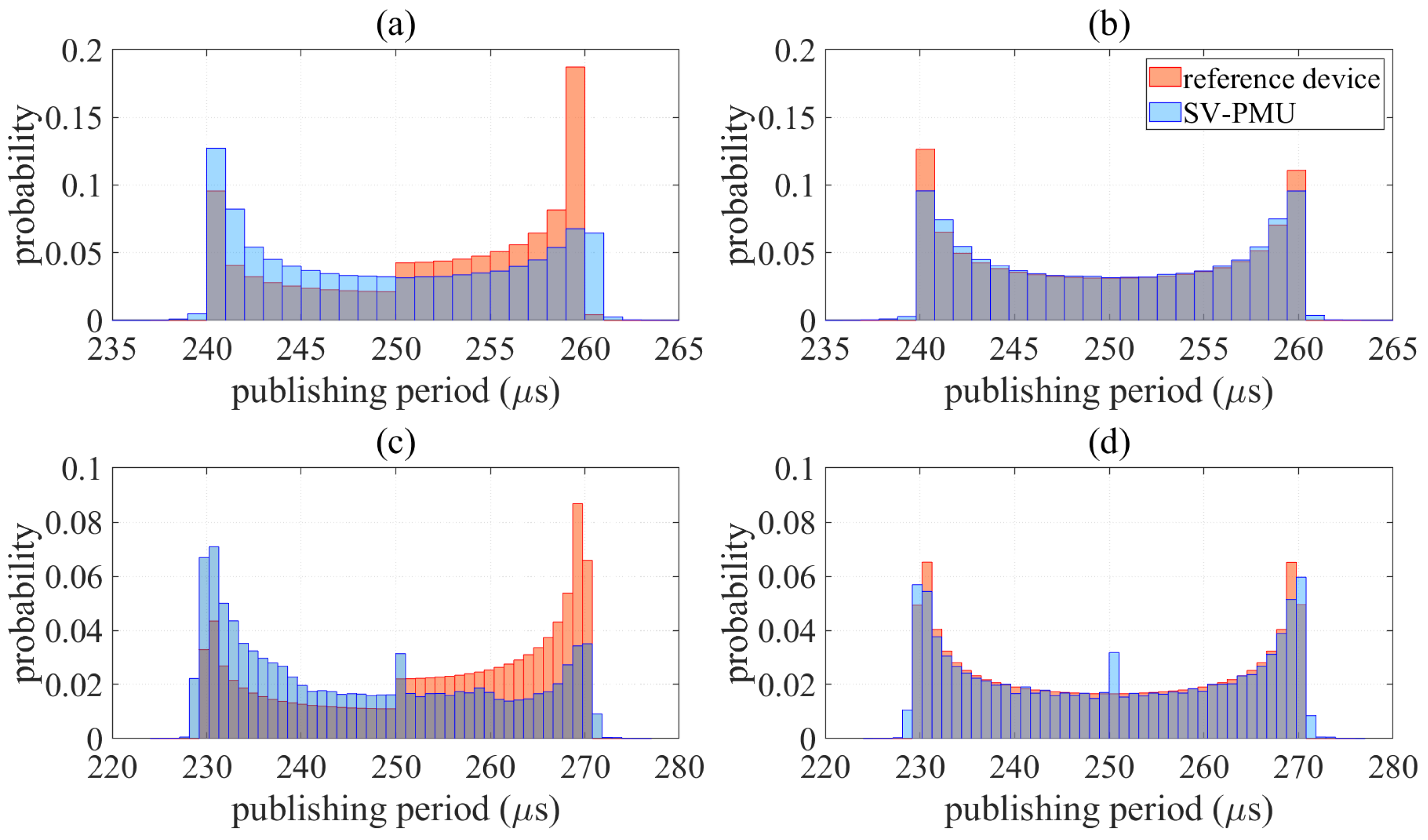
Figure 3 compares the distributions of 120,000 publishing periods measured between packets sent by the reference SAMU and packets received by the SV-PMU. The time periods between the published SV deviate from the nominal publishing period of 250
s according to a sinusoidal function. Four characterization measurements has been performed with sinusoidal deviations realized by combining two different amplitudes and frequencies. A comparison of the histograms suggests that the SV-PMU appears to be more affected by the increase in frequency than the increase in amplitude of the publishing rate variation. The SV-PMU distributions shown in
Figure 3b,d in fact, reproduce better the distributions calculated with the values of the reference SAMU than in the case shown in
Figure 3a,c.
In all the considered configurations, the SV time-stamping functionality does not lose a noticeable number of packets, neither it does introduce outliers. Indeed, the recovered distributions are extremely similar to the original ones, as measured at the reference device side. In this sense, it is reasonable to say that an analysis of the distribution of the SV time-stamps would allow to detect oscillatory publishing rates and thus trigger suitable control actions and checks on the SAMU.
The statistic results presented in
Figure 3 demonstrate the reliability of the SV-PMU in measuring the periods between SVs not published with a constant rate. The limits of
for the frequency at which the packets can be correctly time-stamped by the device is far beyond the values needed for the measurements presented in this article.
4. Measurement Setup
This Section describes the measurement setup used to characterize the proposed method in plausible operating conditions. In order to perform tests in the presence of synchronization issues, a modular measurement architecture, composed of an industrial real-time controller equipped with an FPGA chip and expansion boards, is taken into account. In particular, the first device is the compact RIO (cRIO)9040 that has been developed to replicate the behaviour of a commercial SAMU with the further functionality of simulating the acquisition of SVs through sending packets conforming to the IEC 61850-9-2 standard [
18]. The second device is the cRIO 9068, equipped with a real-time controller and FPGA module. Both devices are equipped with Linux Real-Time O.S.
Time synchronization is performed through the absolute UTC reference provided by the NI-9467 synchronization boards equipped with a stationary GPS receiver with sub-microsecond accuracy. The NI-9467 boards provide the synchronized PPS (pulse-per second) signal to the FPGA and, through the dedicated libraries (FPGA Timekeeper API), allow the different clocks of the prototyping devices to be regulated. For instance, a typical NI cRIO real-time controller has a drift of ±40 ppm, and the FPGA module has a drift of ±100 ppm, which will cause time drifts up to several seconds per day if not synchronized.
In the test characterization, the PPS signal is considered to discipline the FPGA module, allowing for the time tag to be executed up to each FPGA clock tick. To replicate possible synchronization problems encountered in commercial SAMUs equipped with internal GPS receiver, synchronizing signal loss and recovery events is realized in a laboratory environment. In fact, by acting on the GPS antenna connected to the NI-9467 board, it is possible to simulate the absence of the synchronizing signal. In a real context, the lack of the synchronizing signal can be caused by various factors, such as the momentary presence of an obstacle that interferes with the visibility of the satellites or by intentional actions to degrade the synchronizing signal. As shown in
Figure 4, the effect of disconnection of the synchronizing signal causes a momentary absence of the signal that disciplines the FPGA clock, causing a time-dependent drift. When the synchronizing signal is restored, the clock of the FPGA changes from a free-running state to a disciplined state.
However, during the restoration of the synchronizing signal, the FPGA clock takes a variable time to re-establish acceptable synchronization values in order to satisfy requirements for SVs-based applications. The re-establish time to sufficient synchronization value depends on hardware and software factors such as the type of clock employed in the FPGA and the libraries for managing the synchronization discipline. It is possible to observe in
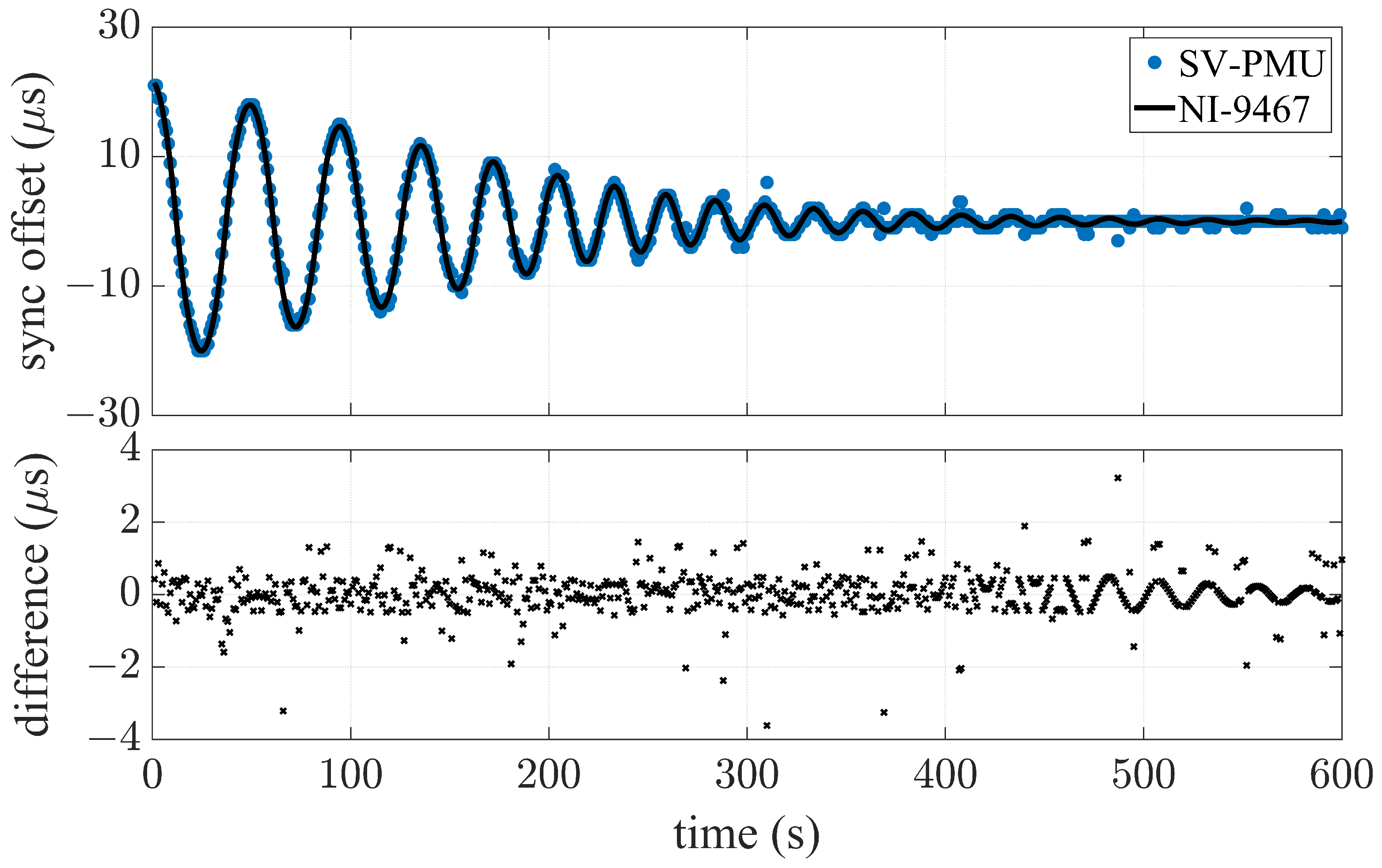
Figure 5 the time trend of the offset obtained as the difference between the time-stamp received by the synchronization board and the time-stamp of the FPGA module with a reporting rate given by the synchronizing signal PPS.
In the considered measurement setup, it is not possible a deterministic model of the clock considered in the GPS receiver NI-9467 due to the absence of specifications in the official datasheet. Nevertheless, based on the different datasets obtained during the experimental characterization, it is reasonable to assume that a synchronization loss induces a damped oscillation whose magnitude, frequency and damping parameters depend on the loss duration and other environmental factors [
34].
5. Time Quality Evaluation
This Section describes an experimental validation of the proposed time-stamping functionality. This analysis aims at quantifying the actual sensitivity in the presence of anomalies in the synchronization chain. To this end, we propose a novel method to autonomously detect and update variations in the PMU time quality and we assess its performance in plausible operating conditions.
More specifically, we considered the case of synchronization failing due to disconnection of the GPS antenna from the NI-9467 board in the reference SAMU system for a few minutes. Such a communication malfunction causes the interruption of the PPS signal output from the FPGA that represents the SAMU synchronization source (see
Figure 4). This leads to a value change in the SV field SmpSync, whose integer is set to 0 indicating an absence of synchronization signal. When the antenna is reconnected, the PPS signal is immediately resumed thus causing the value of the SmpSync field to change again considering the SAMU as synchronized. What it can be observed is instead an offset between the PPS and the GPS signal due to the readjustment of the NI-9467 board oscillator.
Assuming that the SAMU publishes packets with a constant sampling rate, such an offset may affects the time period in correspondence of the PPS transition,
. This is defined as the difference between the time-stamps of the SV packet corresponding to PPS rising edge and the time-stamp of the previous packet. Since the SAMU relies on the PPS to periodically adjust the start of the SV stream, a synchronization offset greater than 1
s leads to a time period offset
, which is defined as the difference between
and the nominal publishing period
as follows:
It is worth mentioning, that in the following presented results we have considered, without loss of the generality, a nominal publishing period of 250
s. In this case, each packet contains the information of a single SV, or more technically: the number of ASDUs (Application Service Data Unit) per frame is equal to 1 (see [
18]). This means therefore that the SV are sent with a configuration whereby the publishing rate is equivalent to the sampling rate, namely:
. Similar results can be achieved, by considering also the other sampling and publishing rate configurations listed in the IEC 61869-9 standard [
35].
Figure 5 shows the comparison between the offset from the synchronization signal measured each PPS transition by the reference system and
as determined by the SV-PMU. For this test, the communication with the GPS antenna has been cut for 10 min and 20 s. It can be noticed that, during this time, the NI-9467 board clock is affected by an offset of 20
s from the GPS time. When the connection is resumed, the reference system oscillator is re-disciplined and, after ten minutes, the offset decreases to values that fall within the typical uncertainty of the instrument.
The bottom plot of
Figure 5 reveals the reliability of the SV-PMU in detecting anomalies in the synchronization of the SAMU with respect to the reference time. The difference between the offset values measured by the reference system and the SV-PMU is comparable, for the most of cases, to the accuracy level of the tested instrument as characterized in
Section 3. It is interesting to notice that the sinusoidal pattern, visible after about 480 s of measurements, occurs when the synchronization offset falls below the 1
s resolution of the SV-PMU.
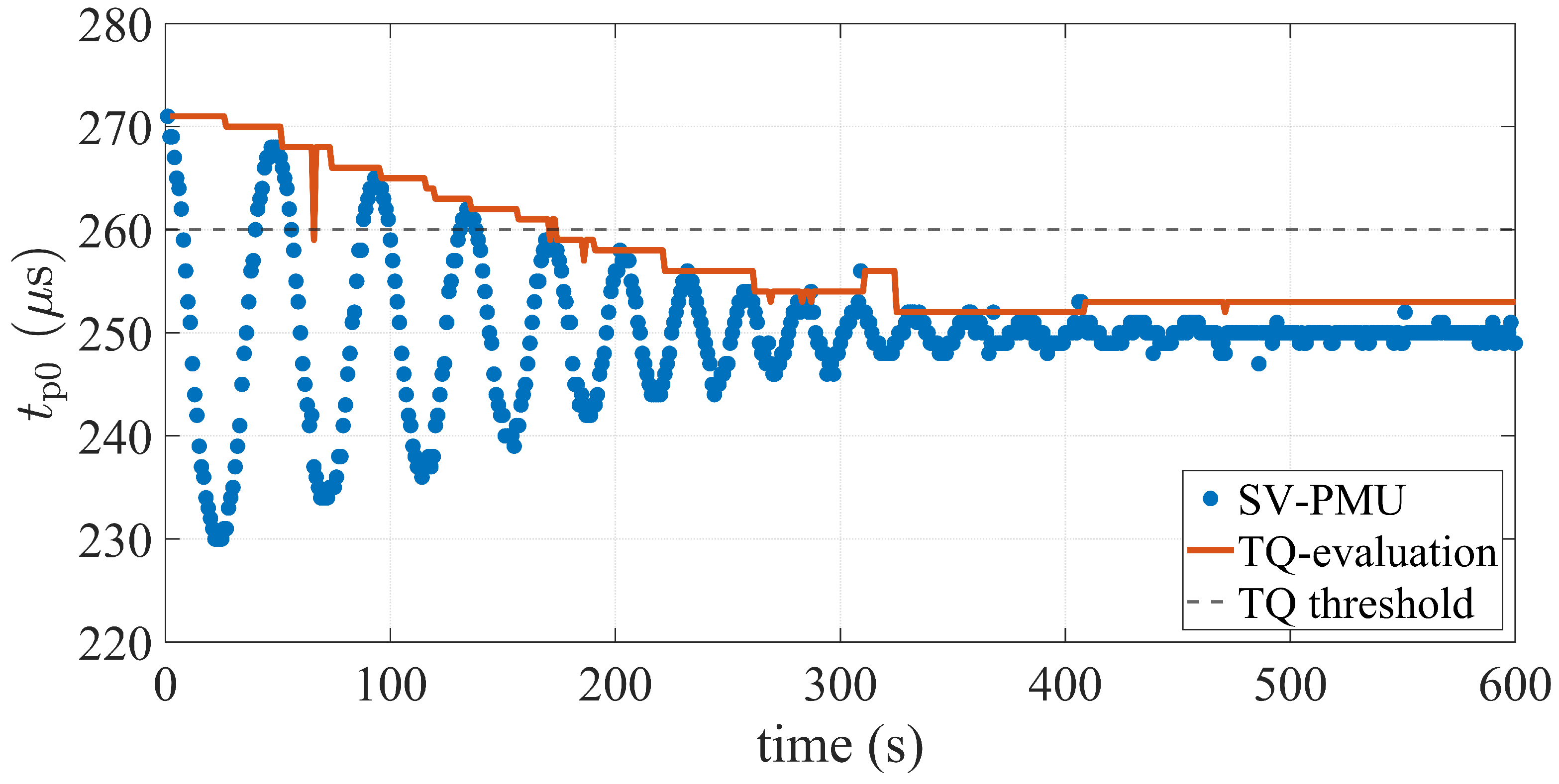
Proven that the SV-PMU is able to measure the offset from the reference time synchronization system with high accuracy, it is reasonable to attempt to provide a real-time estimation of the synchronization status through the update of a time quality index. To this end, a dedicated algorithm, summarized as a pseudo-code in Algorithm 1, has been written and implemented in the Decoder part of the SV-PMU Software structure [
20]. In the following, the main lines of the code that updates the PMU_TQ flag are described.
In the Decoder part of the SV-PMU Software, when the SV packet belonging to the stream of interest is identified, the code performs two actions in parallel. On the one side, it extracts the sample count and the measured current and voltage values, and, on the other side, the arrival time of the SV packet is obtained in terms of an absolute time-stamp provided by the timekeeper running on the FPGA. The proposed time quality evaluation algorithm is added as a new parallel task inside the Decoder loop. In the first if-statement, and its previous value are analyzed and according three different considerations, namely: either the absolute value of is the highest value reached or is detected as a peak, or even the previous value is detected as an outlier peak, the current time quality value is then set. In the first two cases, takes the absolute value of , whereas in the third, it is set to its next-to-last value. If none of these three conditions is satisfied, is set to its previous value.
Subsequently, the value of is checked. If it is below the chosen time quality threshold TQ, the counter increases, otherwise the count is set to 0. This conservative condition implies that the value of is required to fall below the TQ threshold for a specified number of consecutive seconds before updating the status of the PMU_TQ flag. The fulfillment of this condition in this algorithm requires the counter to exceed five consecutive iterations, i.e., five seconds. This value has been chosen on the basis of empirical observations of re-synchronization curves in order to avoid the undesirable impact of certain oscillations that can be misidentified by the algorithm.
The results of the reliability of Algorithm 1 are illustrated in
Figure 6 using the example of reference clock synchronization malfunction previously presented. It can be appreciated how the time quality levels, evaluated at each full second transition, are consistent with the offsets
from the nominal publishing period
corresponding to the detected peaks.
| Algorithm 1: TQ-evaluation in RT |
![Metrology 03 00006 i001]() |
The sparse outliers occurring during the ten measured minutes modify the curve instantly, but do not affect the final result. This is because of the condition set at lines of Algorithm 1, which prevents an outlier mistaken for a peak from representing a problem in terms of the time quality level reported by SV-PMU. Should this occur, during the subsequent iteration of the algorithm (i.e., the second after) it would be possible to detect this failure and revert it to the next-to-last valid value. Thus, these misdetected peaks only have the effect of reproducing isolated dips or spikes, whose value is not maintained for more than one second. Nevertheless, the real time condition prevents these values from being removed.
The outlier occurring after 66 seconds in
Figure 6 is a good example to understand the contribution of this condition on the robustness of the algorithm. Without implementing it in fact, the current time quality variable
would be set to the false peak value and kept for 6 seconds until the next true peak. Hence, as this value falls below the time quality threshold, it would lead to an improper update of the PMU_TQ flag.
By taking as an example the time quality threshold of 10 µs depicted in
Figure 6, it is worth noticing that the values evaluated by the algorithm falls below this line starting at 2 min 54 s from the beginning of the analysis while remaining there until the end. This means that the PMU_TQ flag contains useful information on the synchronization status seven minutes earlier than the reference clock system is completely re-locked to the GPS signal. Exploiting this additional information therefore, could enable a faster comeback to quasi-normal operating conditions.
6. Conclusions
In modern digital substations, the coexistence of different IEDs implies a large variety of possible configurations for the devices’ communication and synchronization. In particular, this paper considers the measurement chain of a PMU that receives as input the SV data stream output by a SAMU. Both the PMU and the SAMU are equipped with independent GPS antennas that guarantee a stable lock to UTC. In this regard, it is though worth mentioning that the two IEDs shall comply with different requirements as specified by the corresponding standards.
If the SAMU loses its lock to UTC, a strict application of the standards’ requirements would imply the entire measurement chain to be not synchronized. As a consequence, also the PMU measurements would be considered invalid until the full restoration of the SAMU synchronization. Such a process could take up to some tens of minutes, with severe consequences on the operation continuity of several PMU-based monitoring and control services (e.g., fault detection or state estimation).
However, a similar approach may prove to be excessively conservative, since it does not take into account neither the remarkable stability of the internal clocks of modern SAMUs and PMUs (even when not disciplined by external sources) nor the potential benefits of such a redundant synchronization configuration.
In order to address this challenge, this paper proposes an alternative approach for the real-time update of the PMU Time Quality flag. Based on the assumption that the PMU internal time-base is still locked to a stable and traceable reference, it is possible to time-stamp the incoming SV packets and evaluate their statistical distribution with respect to UTC time. This analysis is performed in real-time and allows for retrieving useful information about the SAMU synchronization status and upload accordingly the PMU Time Quality flag.
It is worth noticing that the proposed approach does not represent a metrologically rigorous assessment of SAMU synchronization. Indeed, the accuracy and reliability of the obtained results are strongly dependent on the precision and resolution of the PMU time-stamping functionality. Nevertheless, given the remarkable performance of modern industrial controllers, the proposed method may represent a valuable alternative solution in the presence of synchronization losses. In fact, in any monitoring and control system, a partial yet not-fully reliable observation is preferable to a complete absence of information.
In the paper, we characterized the performance of the proposed method in a plausible implementation of the full measurement chain by means of commercially available industrial controllers. We evaluated the accuracy of the time-stamping functionality in the presence of both stationary and oscillatory publishing periods. Based on this test, the PMU has been proven capable of time-stamping the SV packets with a resolution of 1 µs and of tracking time-varying trends with oscillations up to few Hz. Then, we reproduced a typical behavior of a SAMU losing its lock to the external time reference. The proposed method allowed to re-assess the PMU Time Quality within 10 µs in few hundreds of seconds, i.e., several minutes before the SAMU is actually come back to complete and stable synchronization.


