1. Introduction
In the last decades, three-dimensional printing technology has emerged as a novel tool, utilized both for industrial and domestic prototyping. In contrast to conventional manufacturing techniques, three-dimensional printing relies on automated processes using molds to shape a structure in an additive manner by depositing sub-millimeter layers of material [
1]. This allows for greater flexibility in product design, enabling the manufacturer to produce complex geometries and reduce the number of assembly steps required. The ability to create prototypes and iterate designs quickly also reduces the time required to bring a product to the market. Even though some limitations of three-dimensional printing technology exist, such as relatively small-sized printed objects, limited choice of materials for manufacturing, or potential additional steps for material polishing after printing, three-dimensional printing continues to evolve and improve, and it is likely to become an integral part of the manufacturing world.
Having said that, the application of three-dimensional printing has expanded beyond traditional manufacturing into various fields, including the production of low-cost measuring instruments, e.g., optical measurements devices. The opportunity of fabricating custom designed devices, as shown in previous works, such as spectrometers [
2], interferometers [
3], or polarimeters [
4], allows for the creation of specialized instruments, which were previously impossible to create without specific expertise and manufacturing environment. The possible customization of three-dimensional printed models allows for the quick and accurate creation of complex instruments that can be tailored to specific optical systems, which can lead to better performance and precision [
1].
One particular example of the possible importance of three-dimensional technologies is the field of biological research, a constantly evolving area, with growing demand for improved spatial resolution, imaging volume, and high throughput. While there are many commercially available solutions for those specific imaging tasks, they are often expensive, difficult to modify, and lack sufficient documentation to enable users to adapt them for new purposes. Three-dimensional manufacturing has enabled researchers to address these challenges, making the fabrication of adapters, chambers and other accessories more convenient, and they can be easily assembled to an existing microscope stage, increasing its capabilities for various applications, including live-cell imaging or microfluidic experiments [
5].
In their work, Tyson et al. [
6] demonstrated the possibility of developing a custom laboratory equipment that is adapted for use with a brain tissue-clearing technique. A three-dimensional-printed brain-slicing chamber, together with a combined antibody staining and imaging chamber, were produced at a fraction of the cost of commercial equipment.
In another recent work, Villena et al. [
7] presented an affordable, three-dimensionally printed, portable, robotic, mobile-based slide scanning microscope. The device was operated via smartphone with a control app, and it was connected and fully integrated with a telemedicine web platform, where digitized microscopy images were analyzed. The microscope was evaluated in two clinical scenarios with histology and stool samples; however, the device was not compared to a commercially available one.
On the other hand, three-dimensional printing can sometimes, as mentioned earlier, produce a rough surface finish, which can impact the optical performance of instruments, as shown in the work of Li et al. [
8]. Additional post-processing steps may be required to achieve the necessary surface finish, which is discussed in detail in the work of Sharkey et al. [
9].
As previously mentioned, microfluidic devices are an innovative part of today’s biology and science world. Their ability of processing or controlling small volumes of fluid (picolitre range) within micro-channels, ranging in size from tens to hundreds of micrometers [
10], enables scientists to marginally lower the cost of studies, analysis, and research compared to those carried out in a proper laboratory. However, such small objects have very demanding requirements for the utilized optical detection system, one of which is appropriate access for fluid connection and control, usually “from above” [
11]. Due to these specifics, as well as experimental setups, results are monitored with commercial inverted optical microscopes because they enable the user to observe the object from below, keeping the space above the sample free for use [
12]. Because of the positioning of the objective lens underneath the sample, inverted microscopes allow imaging of samples that are attached to the bottom of a container. Inverted microscopes may also have a range of objective lenses with different magnifications, allowing for both high-resolution imaging of small features and a wider field of view for larger structures. In addition to traditional brightfield microscopy, inverted microscopes can also be used with a range of imaging techniques, including fluorescence microscopy, phase contrast microscopy, and differential interference contrast microscopy. These techniques can help to visualize specific features or components within the microfluidic system, such as fluorescently labeled particles or cells.
An example device for “inverted” observations based on a three-dimensional printed microscope was demonstrated by Salguedo et al. [
13] for the observation of mycobacterium tuberculosis colonies. The authors utilized a smartphone, an external 9 V battery, a traditional optical system based on two separate lenses, and three-dimensional manufactured parts to construct a cheap and reliable tool for the observation of the growth of tuberculosis colonies.
However, the average price of a fully equipped microfluidic-dedicated inverted, epifluorescent, heated-stage, programmable microscope for time-lapse observations is no less than 120,000 euros. As a result, the cost of doing microfluidic studies rises to prohibitive levels [
14]. Not only that, but these commercial microscopes are often designed to be used as stationary devices, and their dimensions or weight were never of concern. Another problem is the general design of the device, which the producer strictly defines. This can be seen as a limitation for many scientists and end-users because it does not allow them to manipulate the design according to their needs. All these are drawbacks of commercial inverted microscopes and are a concern for many scientists, laboratories, and developing countries, which utilize microfluidics in their studies.
To the best knowledge of the authors, there is still an existing gap in the development of inverted microscopes using three-dimensional manufacturing techniques. The analysis of existing low-cost three-dimensionally printed inverted microscopes, which were found in the literature, shows relatively low flexibility in terms of construction and utilized parts, as well as the requirement of external battery in order to power the electronics, which makes these microscopes not suitable for long experiments. The present paper discusses the engineering and manufacturing process of a low-cost three-dimensionally printed inverted microscope. However, this is in contrast with the microscope presented in [
13]. The proposed device is utilized specifically for microfluidic experiments and, in contrast to [
13], does not require a smartphone or an external 9 V battery in order to visualize the observed object. After the additional construction steps are presented, several microfluidic experiments are conducted and visualized with the device. In the concluding section of the paper, the benefits and future modifications of the presented prototype are discussed.
2. Prototype Development
2.1. Three-Dimensional-Design and Printing
The prototype was based on the idea of an affordable, portable, three-dimensionally printed inverted microscope. The project was designed from the beginning with the specific optical system in mind, thus remaining lightweight and easy to use. It consists of thirty-three pieces (not including the camera), most of which were designed using the Shapr3D CAD software. The microscope consists of three subsystems: light, optical, and body.
Each part was three-dimensionally printed using a resin- type three-dimensional printer Sonic Mini 4K, produced by the Taiwanese company Phrozen. The used resin was Phrozen ABS-like Resin-gray-50 µm. The printing parameters were a layer height of 0.050 mm, a bottom layer count of 6, an exposure time of 2.500 s, a bottom exposure time of 35.000 s, a transition layer count of 6, a transition type of linear, a transition time decrement of 4.640 s, a waiting mode during printing that is defined as light-off delay, a light-off delay of 10.000 s, and a bottom light-off delay of 10.000 s. Additionally, the following characteristics were included: a bottom lift distance of 6.000 mm, a lifting distance of 6.000 mm, a bottom retract distance of 6.000 mm, a bottom lift speed of 60.000 mm/min, a lifting speed of 60.000 mm/min, a bottom retract speed of 150.000 mm/min, and a retract speed of 150.000 mm/min.
The goal of our prototype was to design a microscope, which builds on the above-mentioned work [
13]. The dimensions of the proposed three-dimensionally printed microscope (presented in
Section 2.4) are considerably smaller than the ones from the work of Salguedo et al. [
13]. Additionally, considering the need of an external battery for energy supply in the work of [
13], the aim of our design was to provide a way to use the microscope for long time-lapses without relying on the capacity of the external electrical source. Therefore, we decided to use a USB cable to power our device (light source and camera), which also eliminated the need for a smartphone.
2.2. Light Subsystem
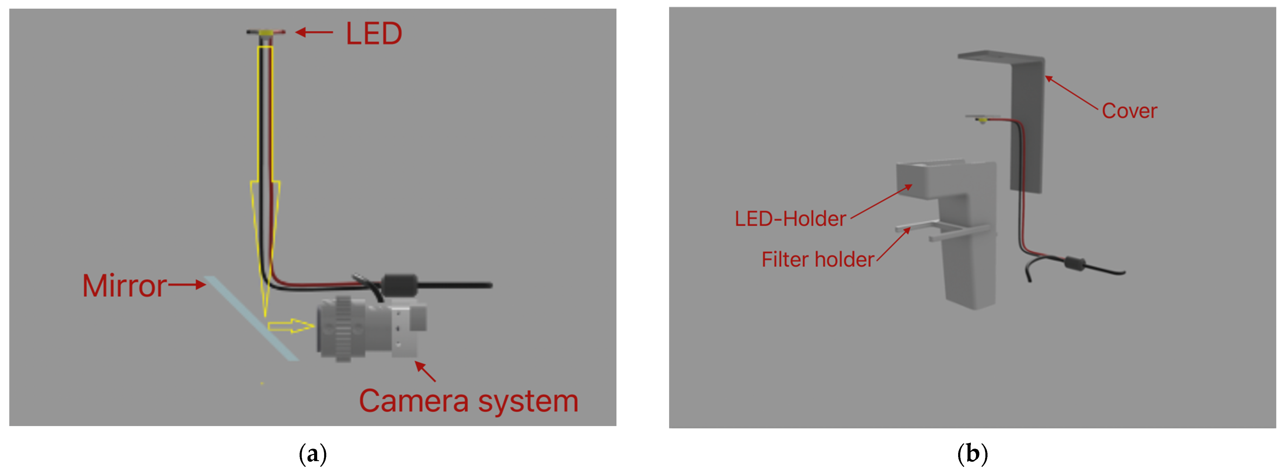
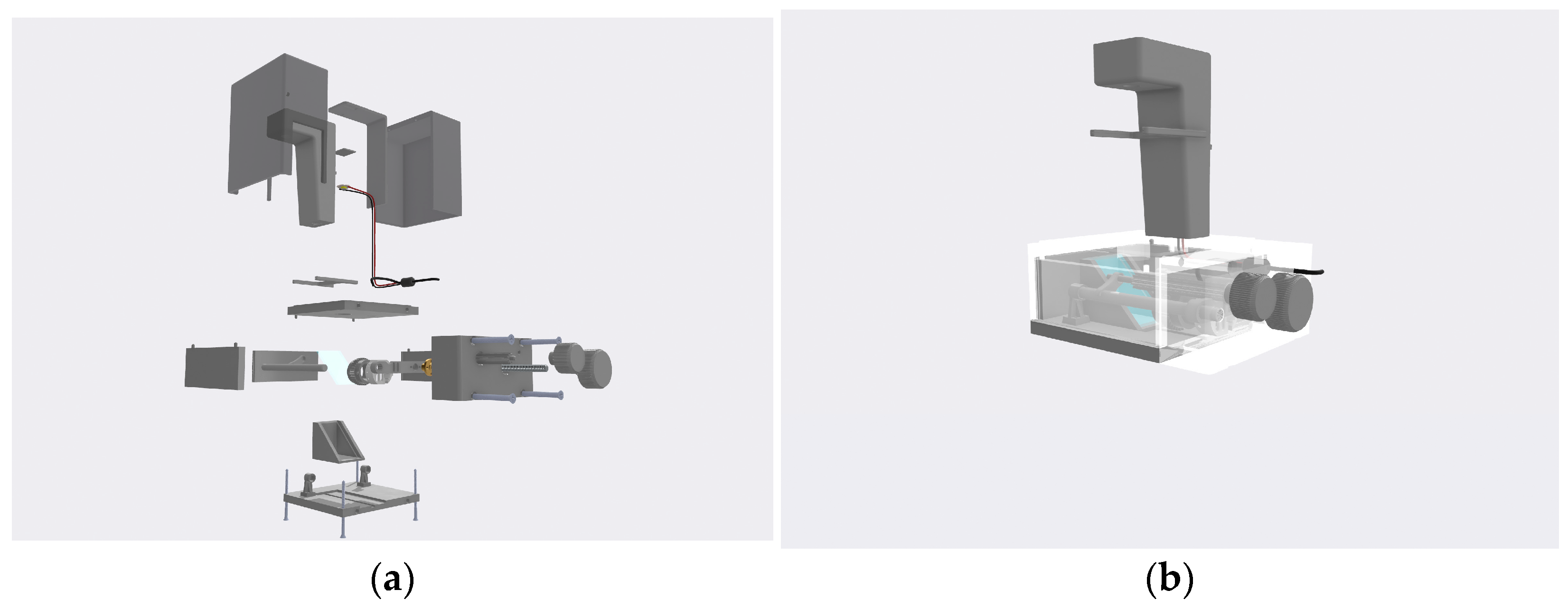
The main function of the light subsystem is to provide enough light for the sample to be visible, as shown in
Figure 1a. This system consists of a white LED with 1 W power, positioned 12 cm above the sample. The LED is housed in a three-dimensionally printed LED–holder attached to the main platform, as shown in
Figure 1b. The electronics for the camera and the LED light are powered using a 5 V USB connection with the computer. The light system also has a detachable part, housing a white cellulose filter, which filters the light so that there is no flickering visible when using the camera. The LED is glued to a three-dimensionally printed piece, which allows it to slide into place in the designated holder. The holder also has a cover that sits on top to prevent damage to the cables and dust accumulation.
2.3. Optical Subsystem
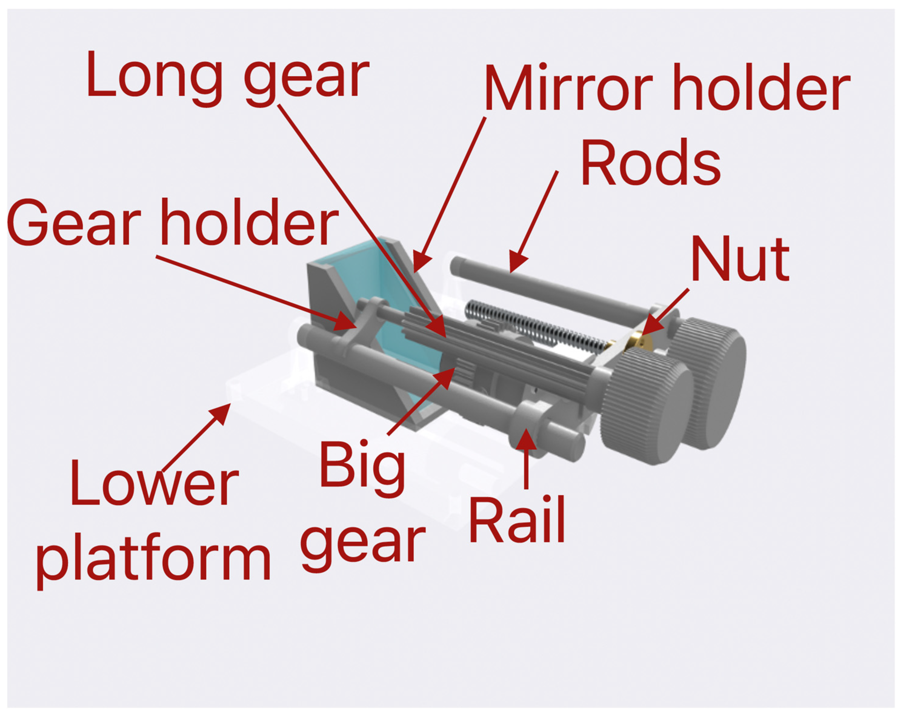
Our three-dimensionally printed microscope has an optical system that uses a simple design, which allows it to be printed at home or in the lab. The main function of this system is to allow focusing, magnification, and observation of the sample. It is based on a mirror placed at a 45-degree angle relative to the sample plane, thus reflecting the light passing through and aiming it towards the camera, as shown in
Figure 2. The mirror is standard and inexpensive. The dimensions of the mirror are 63 mm × 38 mm × 4 mm. It is housed in a designated holder. In this way, it can be adjusted on the platform for optimal viewing angles.
To reduce the price of the optical system and to avoid complications arising from the physical separation of the two lenses, we preferred to extract the optics from a digital microscope camera [
15] with the following parameters:
Image Sensor: 0.3 M HD CMOS Sensor
Photo resolution: 640 × 480
Video Capture Resolution: 640 × 480
Focus Range: Manual Focus from 15~44 mm
Frame Rate: Max. 30 f/s
Magnification: 1600×
Video Format: AVI
Snapshot Format: JEPG/BMP
PC Interface: USB3.0 and USB2.0 and USB1.1
Power Supply: USB Port (5 V DC)
This camera has a magnification of 1600× and has a focusing function. This focusing system consists of a focusing gear, which is fixed to the camera with small screws, as well as a long gear that meshes with the focusing gear via teeth and a rotating knob, which is glued to the long gear and sits outside the microscope. This way, when the knob is rotated from the motion is transferred through the gears to the camera, it allows the focusing to be performed from the outside of the microscope.
To be able to fit the camera in the limited space provided by the platform, it has been stripped out from its casing. Magnification is obtained through a change in the focusing distance. This is performed by sliding the camera on two rods. This action is controlled by a trapezoidal screw, nut, and rotating knob. When rotating the knob, it rotates the trapezoidal screw in the nut. The trapezoidal nut is attached to the camera through a connecting element. Thus, the rotating motion is converted into a translational one and allows the user to move the camera inside the microscope without the need for touching the camera. The light emitted from the LED enters the optical system vertically and is reflected from the mirror horizontally towards the camera, as shown in
Figure 1a. The camera is connected to a computer through a USB and is controlled through the in-built camera app of the computer operating system. In this way, it can be used for real-time observations, for taking snapshots of the samples, or for recording time-lapse observations of the sample.
2.4. Body Subsystem
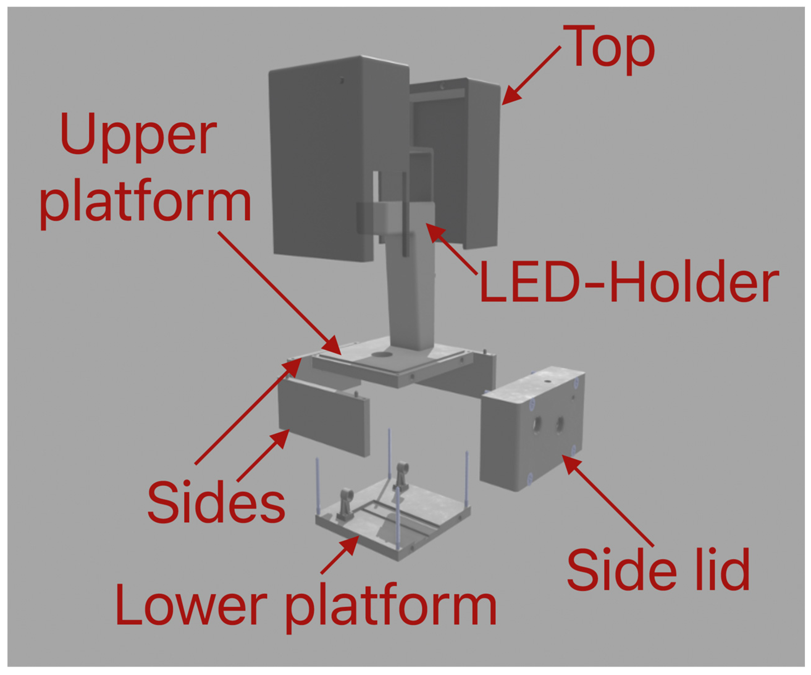
The main function of the body subsystem is to act similar to a skeleton to which all other subsystems are attached and integrate them into one working system. The body of the microscope consists of two platforms (upper and lower), three sides, one side lid, top lid, and an LED unit, as shown in
Figure 3. The upper platform has a size of 130 mm × 135 mm × 13 mm, which is enough for observing samples on microfluidic chips. The lower platform consists of dimensions of 130 mm × 135 mm × 10 mm. It has a channel in which the mirror holder and the mirror can be adjusted to the camera and the holders for the rods on each side of the camera. These holders act as the final part of the optical system and allow the camera to be positioned above the platform to observe the light reflected from the mirror. Three parts (sides) are situated between the upper and lower platforms. Two of them have fixing elements to connect with the upper platform. The third one slides between the other two. Both platforms and all the sides are fixed to each other using four M4 screws with a length of 67 mm. In this way, the construction is durable and easy to build. To this construction, a side lid is bolted using four M6 screws with a length of 48 mm. The function of the side lid is to enlarge the interior space so that the camera has more room to zoom in and zoom out. The side lid also houses the two rotating knobs, with which the main functions of the optical system (focusing and zooming) are controlled. The LED unit is mounted on top of the upper platform using three M3.5 screws with a length of 15 mm. The LED unit houses the LED cables and has an external attachment to filter the light. The top lid is made up of two parts to allow for easier printing process. After printing, both sides are glued together. The dimensions of this part are 130 mm × 135 mm × 155 mm. The function of the lid is to prevent unwanted light and dust from entering the system. It can be easily removed if the conditions of the room allow for it. In
Appendix A, the assembly process of the whole device is shown.
2.5. Microscope Magnification
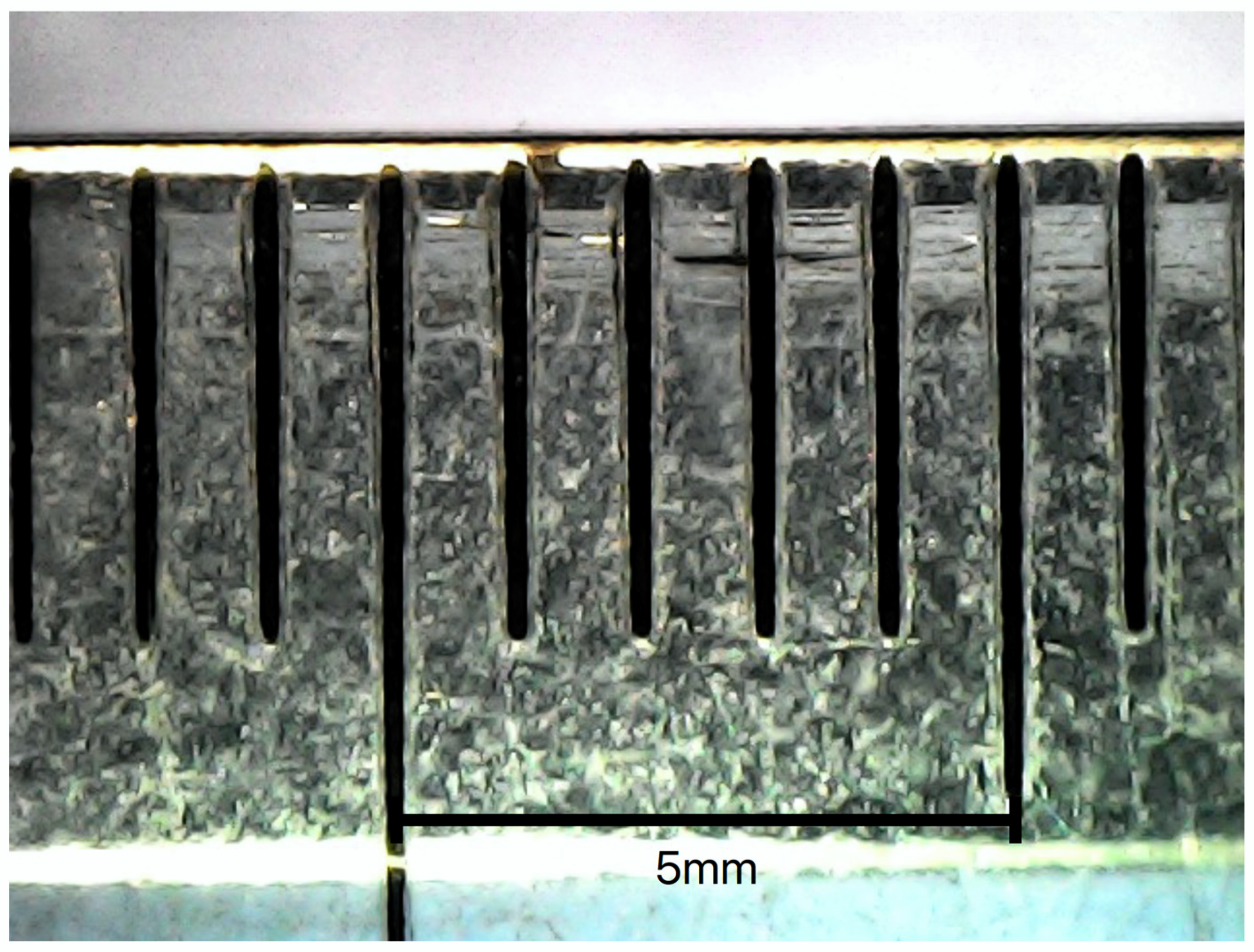
In order to determine the maximum magnification of the three-dimensionally printed inverted microscope we have designed, a picture of a ruler shown in
Figure 4 was taken. The measurement of the actual distance directly from the figure was taken. The 5 mm shown in
Figure 4 correspond to 14.5 cm, which equals a maximum magnification of 29×.
3. Results
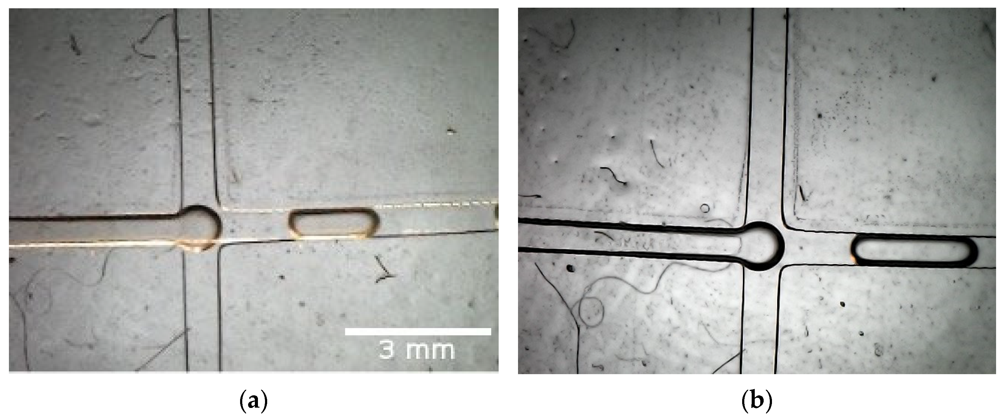
After the microscope was constructed, several microfluidic experiments were conducted to observe the quality of the designed chips. All devices were created from polydimethylsiloxane (PDMS) and poured into a three-dimensionally printed resin mold. The procedure was already described in our previous work [
16]. In the first experiment, a flow-focusing junction for droplet generation was created, similar to the one described in [
17]. Lysogeny broth (LB) with
Escherichia coli (
E. coli) cells was used as a continuous phase in the main channel (width × height—600 µm × 600 µm), as shown in
Figure 5a, and mineral oil was used as a dispersed phase in the two side channels (width × height—600 µm × 600 µm). The cells were cultured in the LB medium and left overnight in a shaker incubator at 37 °C before the beginning of the experiment. In the second case, distilled water (DW) was utilized as a continuous phase.
Figure 5 presents the resulting droplets. Bigger droplets were observed in the second experiment, as described in [
18], mainly due to the lower viscosity of pure DW, compared to the LB medium with cells inside. As described in our previous work, these big-sized droplets characterize the so-called dripping regime, in which pressure gradients across the droplet play important roles in the bubble generation.
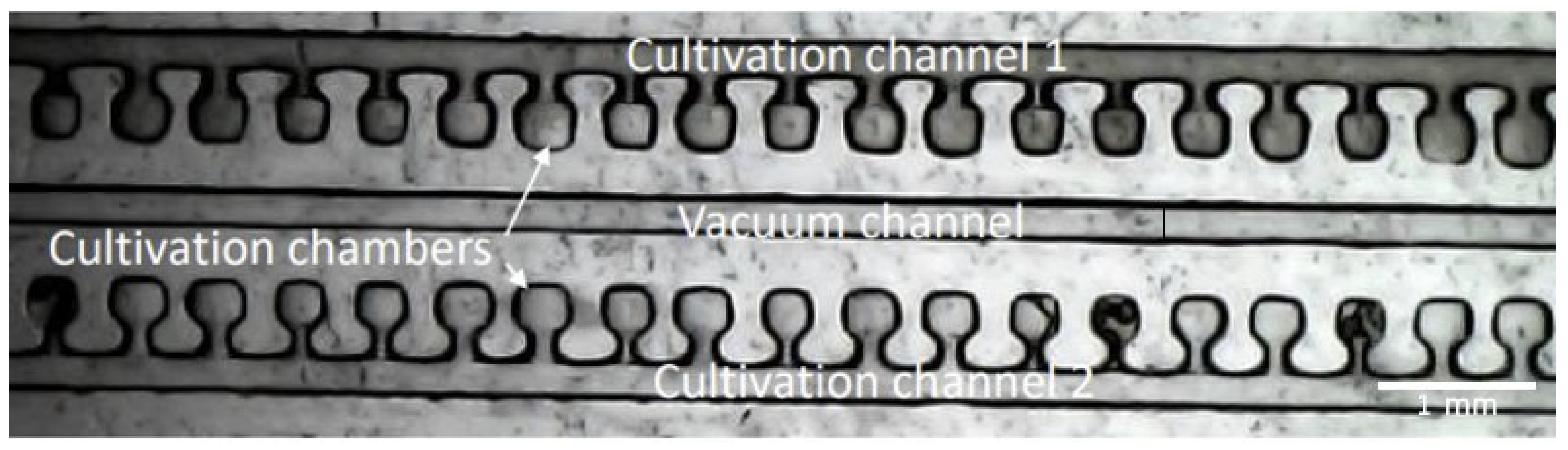
In the second experiment, we utilized the capacity of PDMS for gas permeability and developed a device for the rapid screening of bacterial antibiotic susceptibility. Bacterial cells (
E. coli) were isolated in cultivation chambers (300 µm × 300 µm × 200 µm height) with the help of the vacuum-sucking channel (220 µm × 220 µm). After the chambers were loaded with cells, the first cultivation channel was filled with Chloramphenicol antibiotic (CA) + LB, using a syringe pump at a constant flow rate. The second cultivation channel was utilized to replicate the natural habitats of the bacteria and filled only with LB as a nutrient-rich medium. The device was then placed on a 37 °C heated plate to achieve optimal cell growth conditions. Bacteria cell growth was then monitored visually. A detailed description of the results was carried out in [
16].
Figure 6 shows a picture made with the above-described inversed microscope of the novel chip 1 h after the filling of the chambers and cultivation channels. With the help of the device and the microscope, we were able to successfully populate more than 100 cultivation chambers and monitor bacterial growth in the presence/absence of antibiotic compounds. As visible in
Figure 6, a clear difference between the chambers with pure LB (Cultivation channel 1) and the chambers with LB + CA (Cultivation channel 2) is present. A bacterial growth is detected in the channel without antibiotics (lower pixel intensity). With the help of a microscope, one can easily detect antibiotic resistance after approximately 6 h [
16], without the need for single-cell analysis. Even though the results of other studies regarding antibiotic susceptibility screening look more promising, the proposed microscope offers an affordable tool for point-of-care diagnostics.
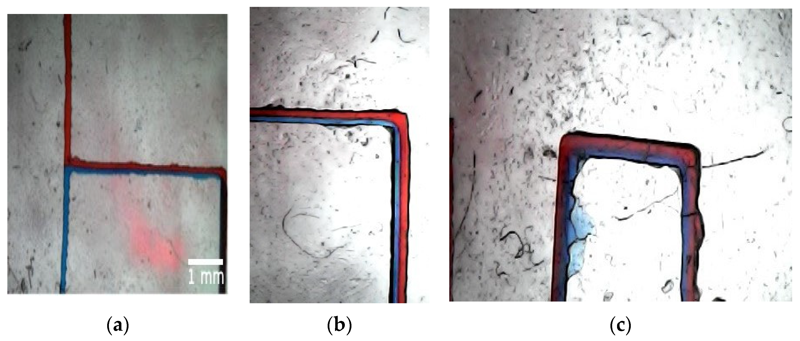
In the last conducted experiment, we discussed the concept of fluid mixing in microfluidic channels. In this passive mixing, solutes from two fluids diffuse across their interface downstream along a channel, generating a concentration gradient normal to the flow direction. In our case, the two miscible fluids, DW + azorubine dye in red and DW + triarylmethane dye in blue, were introduced into a T-mixer from two separate channels, each having size of 200 µm in width and 200 µm in depth. Both liquids had a volume flow rate of 9.9 mL/h.
As mentioned in the introduction section, the fluid flow in microfluidics is characterized by a small Reynolds number (Re < 10) due to the small channel sizes. The Reynolds number is defined as uL/ν, where u is the flow velocity in the microchannel, L is the characteristic length of the microchannel, and ν is the kinematic viscosity of the fluid. In our case, the viscosity of pure water was taken into account, since the volume fractions of the two dyes were negligibly small (around 1%) compared to the whole volume of the fluid. With a characteristic length L of 200 µm, we have a Re = 0.15 for the discussed case.
As shown in
Figure 7a a clear interface between the two fluids is distinguishable. When the two liquids mix, the solution turns into purple color, showing the extent of diffusion and the development of mixing,
Figure 7c.
4. Discussion and Future Improvements
It is visible from
Figure 5 that the camera successfully captures the presence of
E. coli in the droplets. However, it is still difficult to observe the bacteria at the single-cell level, even at the maximum zoom setting.
Our objective in this project was to design and manufacture an inverted microscope suitable for biological labs and microfluidics and at the same time to be reliable and incredibly cheap compared to fully equipped commercial inverted microscopes.
Table 1 summarizes a comparison between our three-dimensionally printed inverted microscope and a professional commercial microscope.
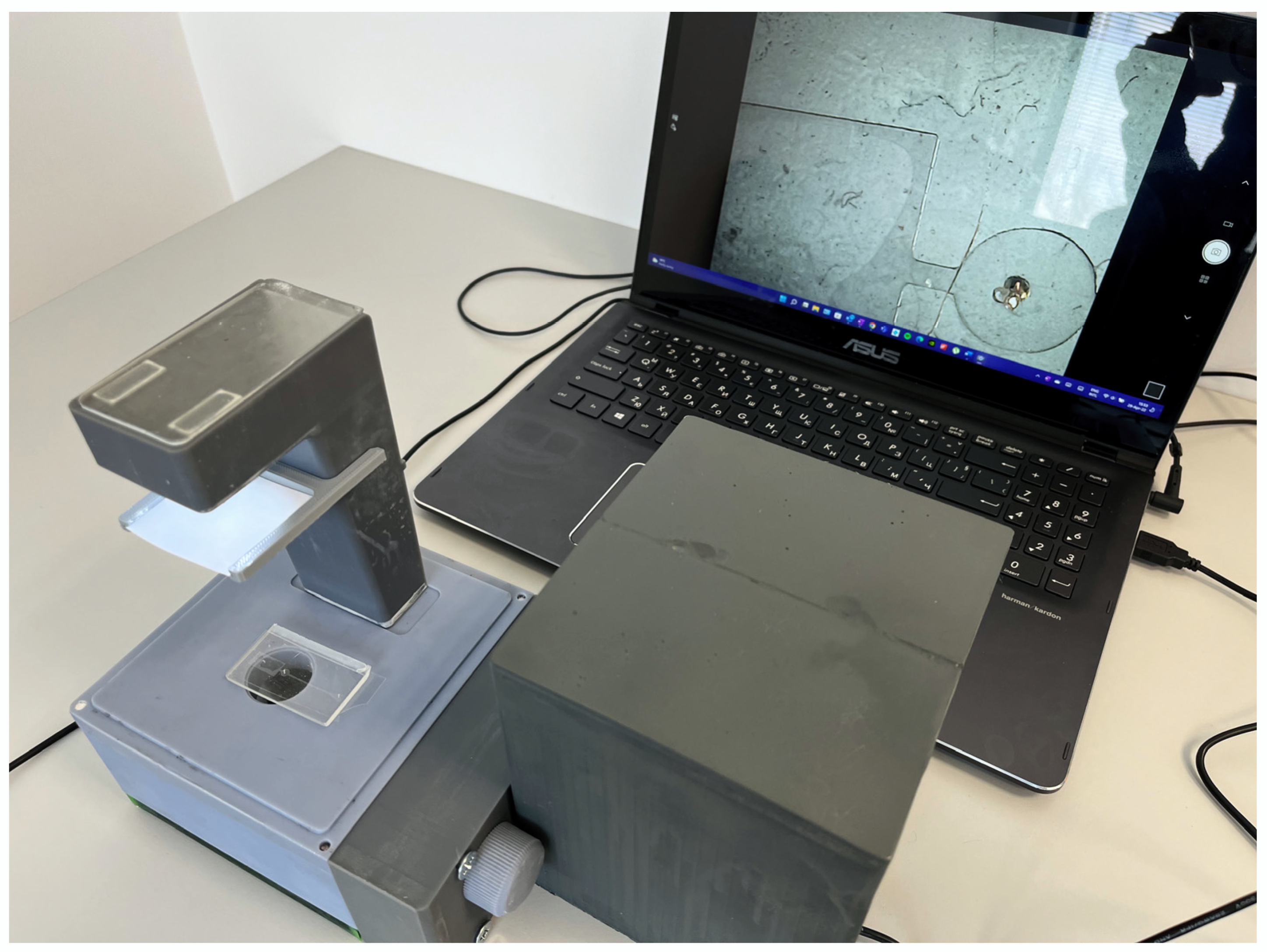
Figure 8 shows our low-cost three-dimensionally printed inverted plug-and-play optical instrument for microfluidics imaging, which is fully assembled and connected to a computer using the USB interface. In many laboratories around the world, resources are not enough to afford a commercial inverted microscope, which greatly limits the capabilities for observation. With our microscope, we demonstrate that observation of microfluidic devices can be successfully carried out at 1/2000 of the cost, without losing the main function of a commercial inverted microscope, i.e., it magnifies and focuses the image obtained from the passage of the light through the sample. There are a couple of existing low-cost microscopes around the world, which are commercially available. However, the main advantage of the proposed device is that it offers the end-user the flexibility to modify most of the parts according to their needs or even increase the functionality if needed. It also shows that ultra-high resolution and definition are not necessary for the correct interpretation of results using microfluidic devices.
When comparing our system to other low-cost three-dimensionally printed inverted microscopes, which were found in the literature [
13], several main advantages of the presented microscope should be outlined:
Compact and lightweight design (
Table 1)—the dimensions of the model proposed here were found to be considerably smaller compared to the one described in [
15].
The costs for producing the proposed device (around 60 EUR, including the camera) were found to be lower compared to [
13].
Compared to the microscope of Salguedo et al. [
13], in which an external battery is used to power the light and the observation relies on the smartphone battery, we included a direct USB connection to a computer, which allowed for long experiments (more than 12 h) without a need to recharge or replace batteries.
In the future, our project will continue to evolve with the introduction of new parts and functions, such as upgraded camera quality, a heated stage, which will allow for optimal cell growth conditions and for monitoring this growth, an ultra-violet light source enabling fluorescence experiments, such as [
18], magnetic construction for easier assembly, improved zoom function and internal space, and weight-saving materials and solutions, such as thinner wall constructions. These improvements will allow our microscope to gain another functionality of professional inverted microscopes and keep the price at a relatively low level. Additionally, the introduction of a new camera with a bigger sensor and higher resolution will further improve the quality of the images captured and will offer a better view of the processes inside the channels. As previously described, the maximum magnification of the microscope is 29× (
Figure 4). This, however, may not be enough for some studies. This is why, in future iterations in combination with a new camera with better resolution, an additional lens could be used and placed directly below the opening for the sample and above the mirror. This will allow for an increase in the maximum magnification, and, depending on the desired magnification, it could be possible to change the lens to a better one. This will further enhance the abilities of our three-dimensionally printed inverted microscope.

 ,
, 


