

Design and Concept of Renewable Energy Driven Auto-Detectable Railway Level Crossing Systems in Bangladesh

 , , ,
, , ,  ,
,  and
and 
Abstract
:1. Introduction
2. Automatic Level Crossing System Architecture and Components
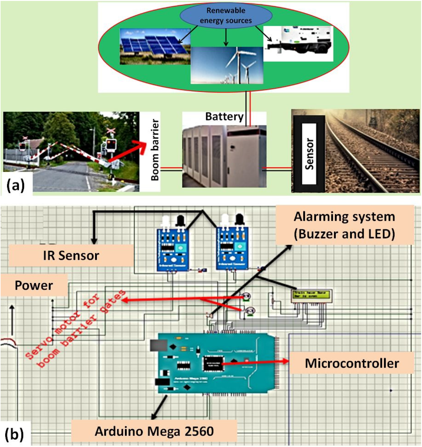
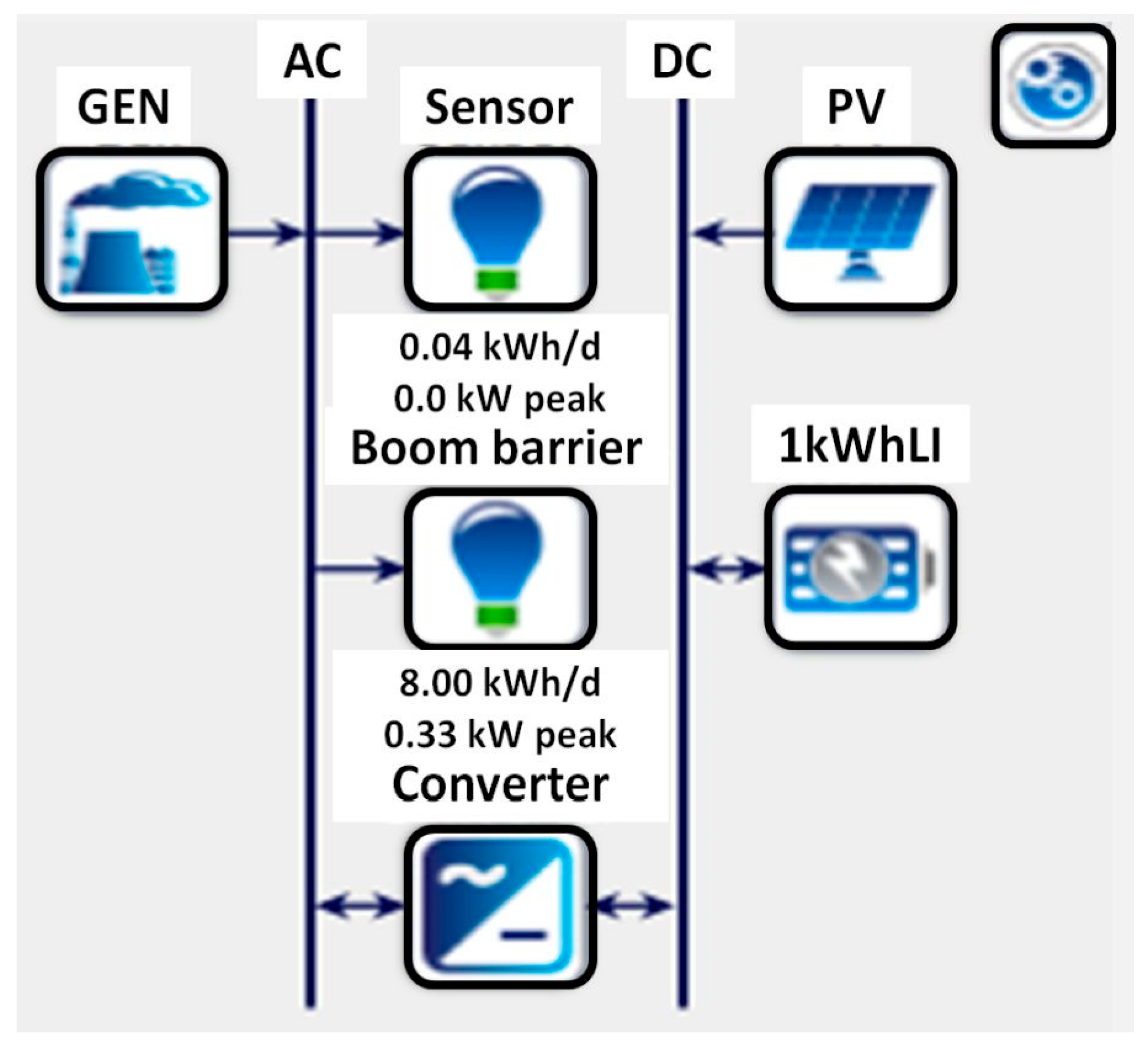
2.1. Architecture of the Automatic Level Crossing System
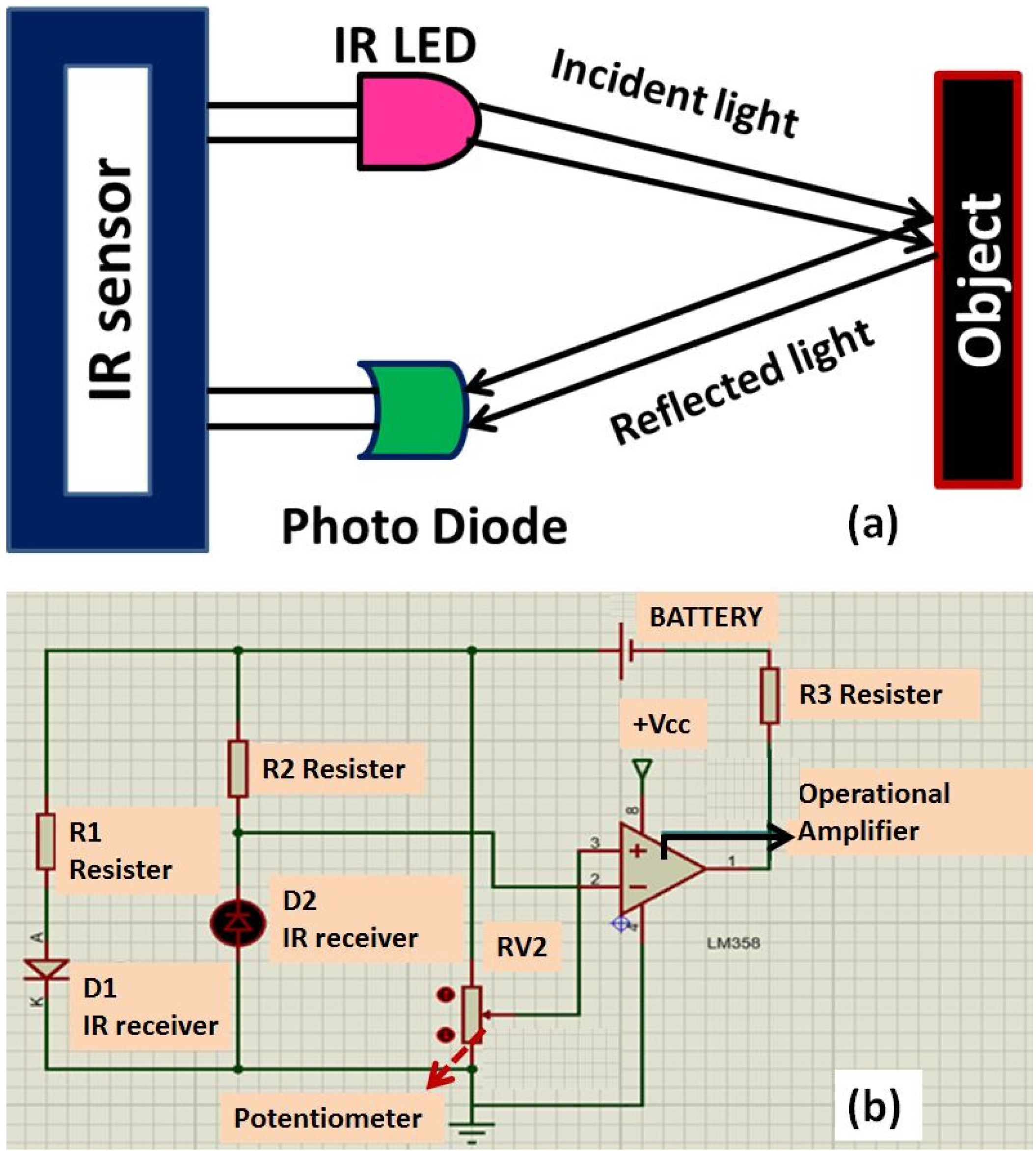
2.2. Sensor
2.3. Battery
3. Power Generation System Components and Simulation Results
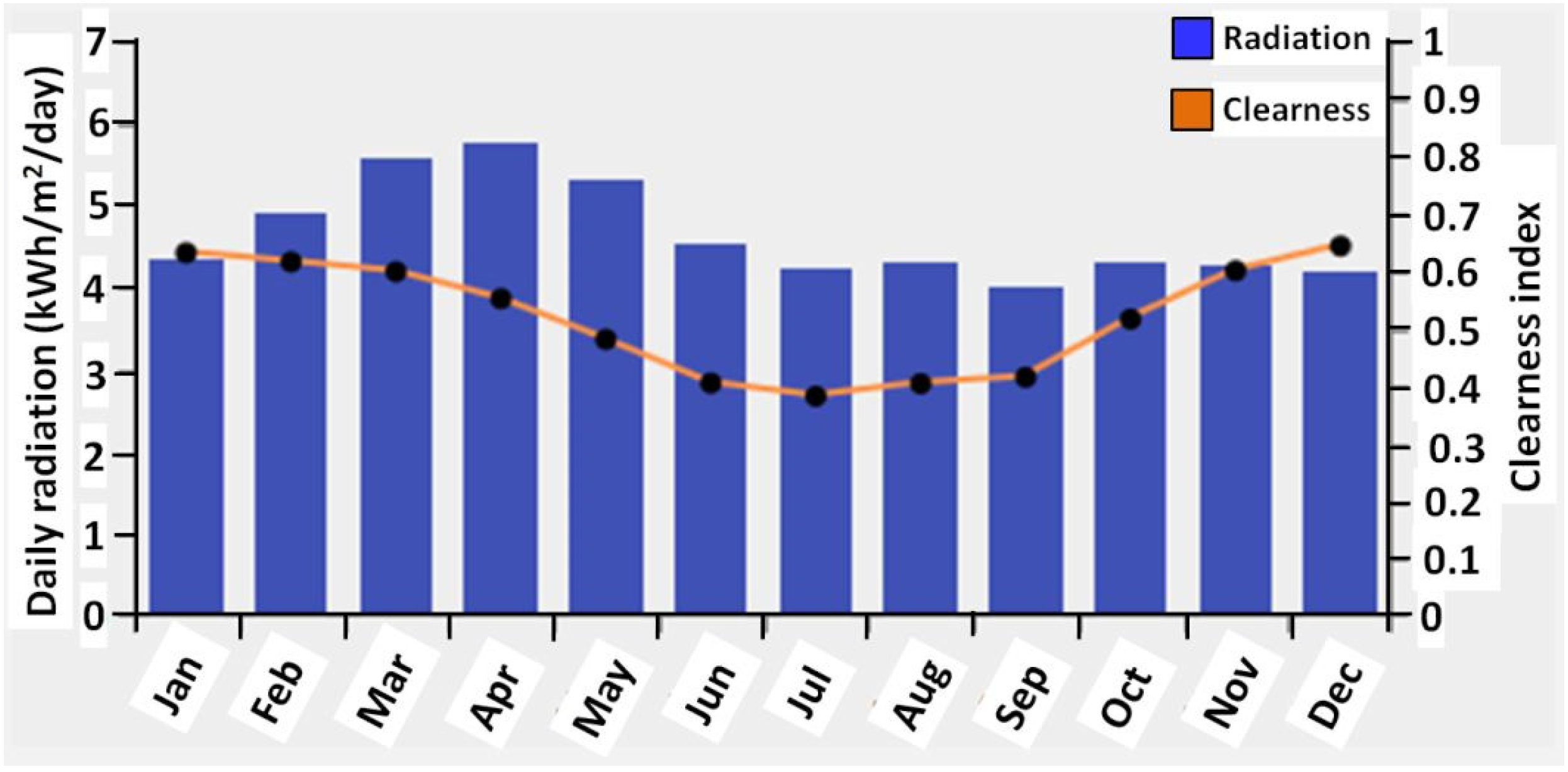
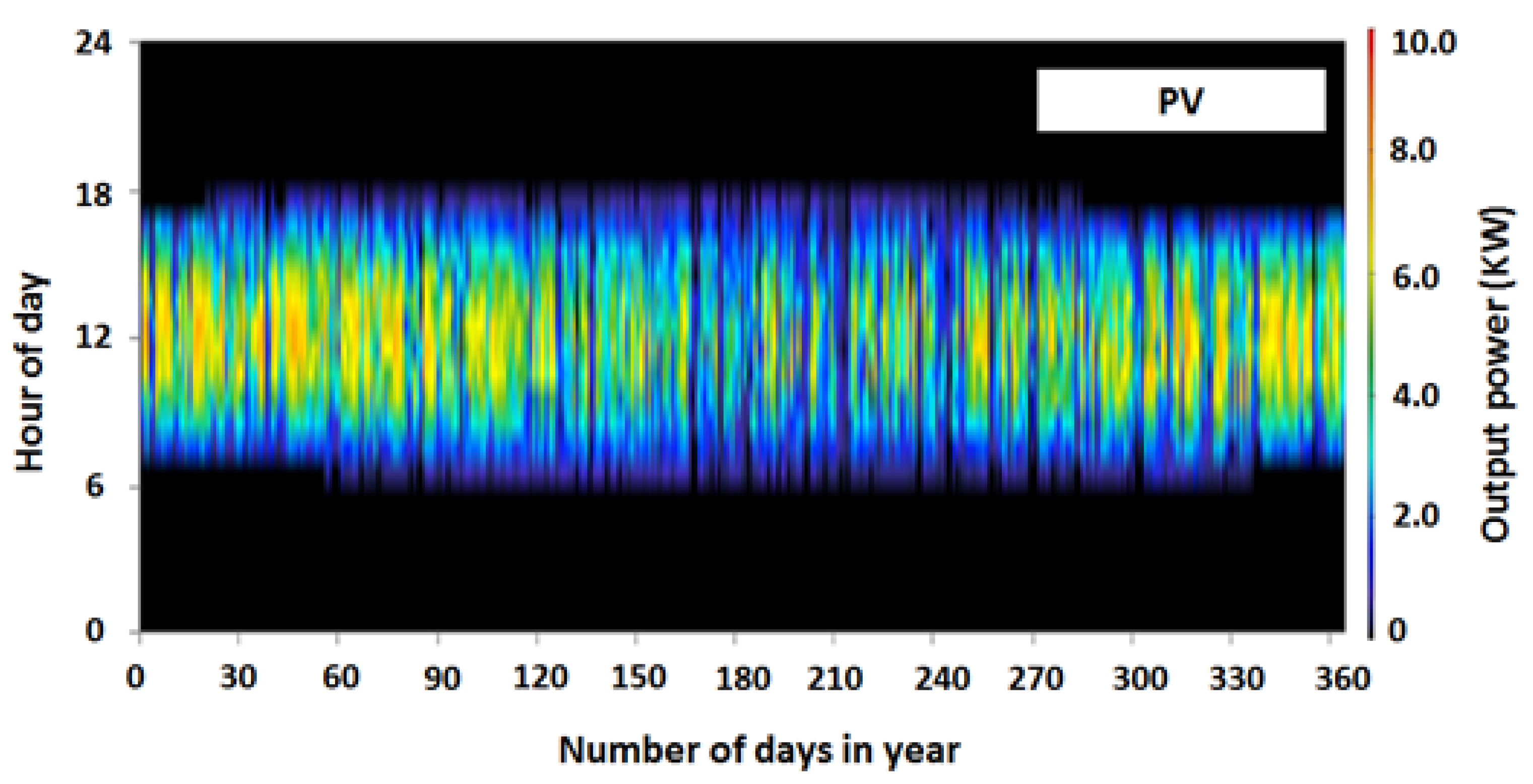
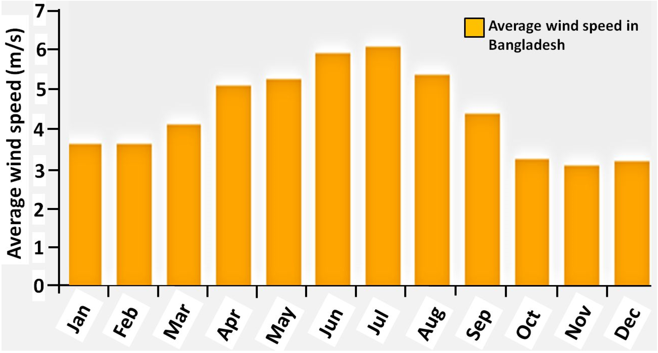
3.1. PV Panel
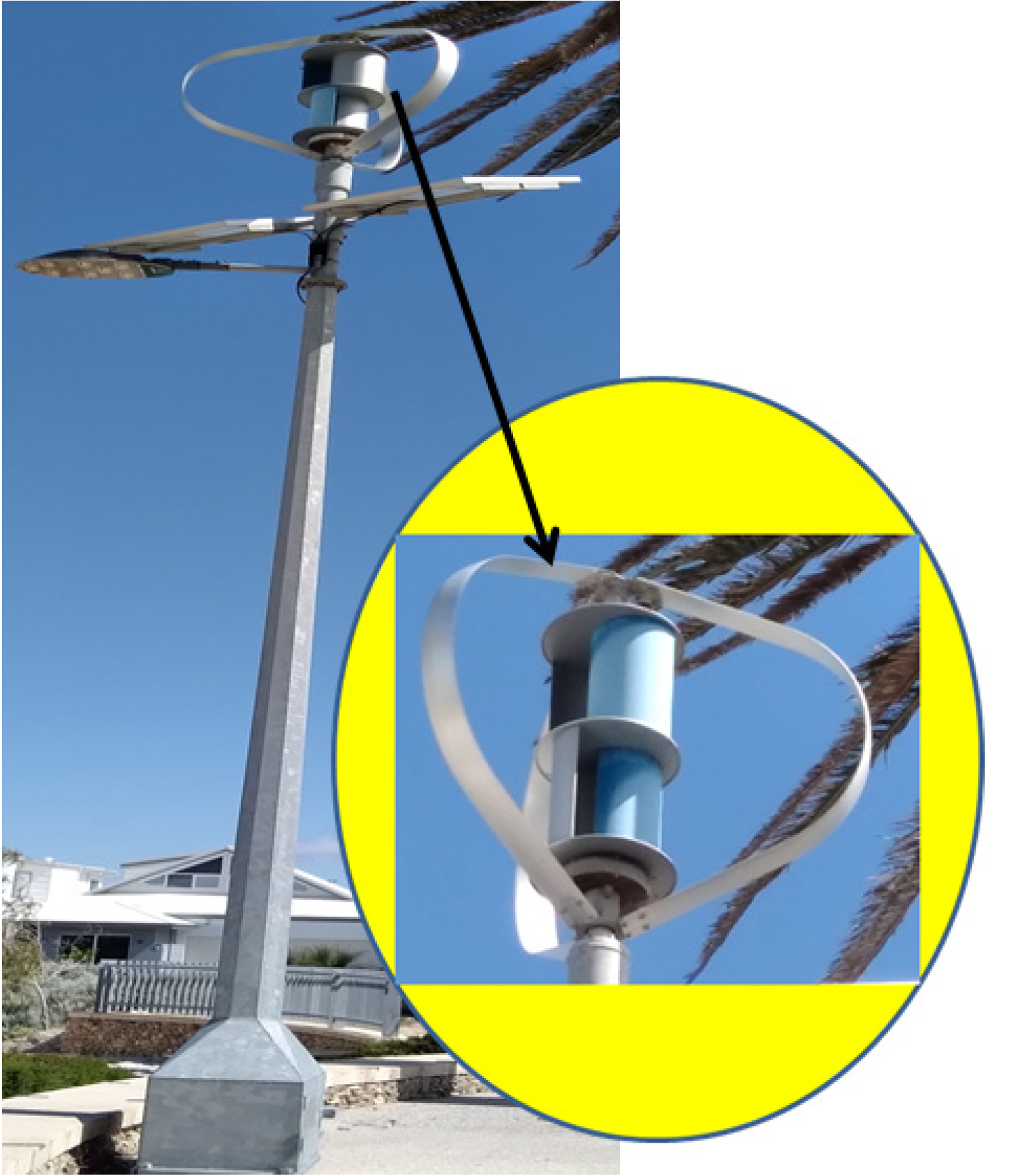
3.2. Wind Turbine
3.3. Generator
3.4. Converter
3.5. Hybrid Power Generation Systems
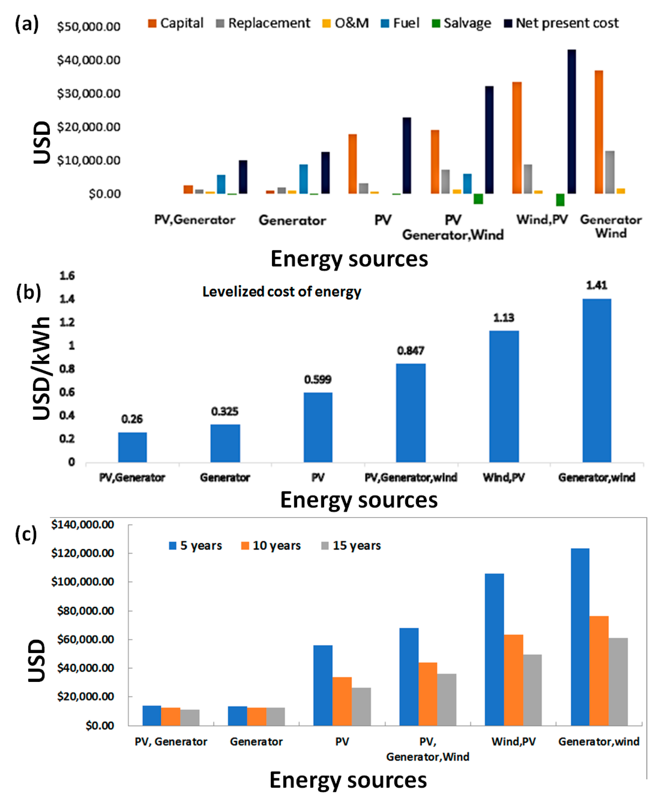
4. Cost Analysis
5. Discussion
- (i)
- Development of automatic railway crossing systems all over the country to reduce unexpected accidents;
- (ii)
- Generate enough renewable energy for the railway crossing systems and store the excess energy generated from the site for emergency cases;
- (iii)
- To reduce pressure on the national grid to help the country to deliver the energy demanded in other sectors;
- (iv)
- Ensure the harvesting of renewable energy for sustainable development.
6. Conclusions
Supplementary Materials
Author Contributions
Funding
Institutional Review Board Statement
Informed Consent Statement
Data Availability Statement
Acknowledgments
Conflicts of Interest
References
- Railway Information Book 2018. Bangladesh Railway. Available online: http://railway.portal.gov.bd/sites/default/files/files/railway.portal.gov.bd/page/3951d3b2_dcc8_463d_9657_4e3cc6e49b8b/Information%20Book%202018%20(3).pdf (accessed on 5 October 2021).
- Azzacy, M.B. Analysis of rail accidents due to collision and their preventive measures in Bangladesh. Ph.D. Thesis, Bangladesh University of Engineering and Technology, 2012. Available online: http://lib.buet.ac.bd:8080/xmlui/handle/123456789/454 (accessed on 9 November 2022).
- Selvan, T.A.; Viswanathan, A.; Madhankumar, S.; Dhanush Kumar, R. Design and Development of an Automatic Unmanned Railway Level Crossing Gate. IOP Conf. Ser. Mater. Sci. Eng. 2021, 1059, 012005. [Google Scholar] [CrossRef]
- Balamurugan, C.R.; Vijayshankarganth, P.; Alagarraja, R.; Subramanian, V.E.; Ragupathy, R. Automatic Railway Gate Control System Using 8051micro Controller. Int. J. ChemTech Res. 2018, 11, 63–70. [Google Scholar] [CrossRef]
- Babylatha, M.; Pranitha, K.; Jhansidevi, P.; Shilpa, T. Automatic railroad level crossing systems using AGM technologies. Indian J. Comput. Sci. Eng. IJCSE 2015, 8, 558–563. [Google Scholar]
- Moorthy, P.; Vishnupriya, P.; Poornima, N.; Priyadarshini, R.; Kharche, S. Automatic Railway Level Crossing Using LoR. Int. J. Res. Anal. Rev. IJRAR 2020, 7, 421–424. [Google Scholar]
- Singh, P.; Pasha, J.; Khorram-Manesh, A.; Goniewicz, K.; Roshani, A.; Dulebenets, M.A. A Holistic Analysis of Train-Vehicle Accidents at Highway-Rail Grade Crossings in Florida. Sustainability 2021, 13, 8842. [Google Scholar] [CrossRef]
- Abioye, O.F.; Dulebenets, M.A.; Pasha, J.; Kavoosi, M.; Moses, R.; Sobanjo, J.; Ozguven, E.E. Accident and hazard prediction models for high-rail grade crossing: A state-of-the-practice review for the USA. Rail. Eng. Sci. 2020, 28, 251–274. [Google Scholar] [CrossRef]
- Singh, P.; Dulebenets, M.A.; Pasha, J.; Gonzalez, E.D.R.S.; Lau, Y.-Y.; Kampmann, R. Deployment of autonomous trains in rail transportation: Current trends and existing challenges. IEEE Access 2021, 9, 91427–91461. [Google Scholar] [CrossRef]
- Pasha, J.; Dulebenets, M.A.; Singh, P.; Moses, R.; Sobanjo, J.; Ozguven, E.E. Towards improving sustainability of rail transport by reducing traffic delays at level crossings: A case study for the state of Florida. Clean. Logist. Supply Chain. 2021, 1, 100001. [Google Scholar] [CrossRef]
- Mathew, J.; Benekohai, R.F.; Berndt, M.; Beckett, J.; McKerrow, J. Multi-critieria prioritization of highway-rail grade crossings for improvements: A case study. Urban Plan. Transp. Res. 2021, 9, 479–518. [Google Scholar] [CrossRef]
- Pasha, J.; Dulebenets, M.A.; Singh, P.; Moses, R.; Sobanjo, J.; Ozguven, E.E. Safety and delays at level crossings in the United States: Addressing the need for multi-objective resource allocation. In Sustainable Rail Transport 4. Lecture Notes in Mobility; Marinov, M., Piip, J., Eds.; Springer: Cham, Switzerland, 2020. [Google Scholar] [CrossRef]
- Ilampiray, P.; Deepak, K.; Santhosh, M.G.D.; Kishore, S. Automated railway gate control system using Arduino and ultrasonic sensors. J. Phys. Conf. Ser. 2021, 1916, 0120081. [Google Scholar] [CrossRef]
- Shetty, R.; Patel, P.; Sampat, A.; Shukla, S.; Singh, A.K.; Deshmukh, P. Automated railway crossing and obstacle detection. In Proceedings of the 2nd International Conference on Advances in Science & Technology (ICAST-2019) K.J. Somaiya Institute of Engineering & Information Technology, University of Mumbai, Maharashtra, India, 8–9 April 2019. [Google Scholar]
- Banerjee, S.; Mondal, S.; Chakraborty, A.; Chattaraj, S. Global Positioning System Based Automated Railway Level Crossing. Available online: https://www.researchgate.net/publication/344789112 (accessed on 9 November 2022).
- Dent, M.; Marinov, M. Introducing Automated Obstacle Detection to British Level Crossings. In Sustainable Rail Transport Lecture Notes in Mobility; Fraszczyk, A., Marinov, M., Eds.; Springer: Cham, Switzerland, 2019. [Google Scholar] [CrossRef]
- Tshaai, D.C.; Mishra, A.K.; Pidanic, J. Demonstration of smart railway level crossing design and validtioa using data from metro rail South Africa. J. Adv. Transp. 2022, 2022, 6614242. [Google Scholar] [CrossRef]
- Liyanage, T.D.; Jayathilake, M.V.M.; Abeysinghe, D. Secure Based Railway Crossing and Controller Room Management System Using IoT. In Proceedings of the CSRS 2021, Colombo, Sri Lanka, 26 November 2021; Available online: https://www.researchgate.net/publication/356556856 (accessed on 9 November 2022).
- Bhuyan, M.H.; Rahman, S.M.M.; Tarek, M.T. Design and simulation of a PLC and IoT-based railway level crossing gate control and track monitoring system using LOGO. IOSR J. Electr. Electron. Eng. IOSR-JEEE 2022, 17, 13–23. [Google Scholar]
- Mahfuz, M.B.; Ali, Z.M.; Hossain, M.S.; Das, A. Development of a smart railway system for Bangladesh. In Proceedings of the 2017 IEEE Region 10 Conference (TENCON), Penang, Malaysia, 5–8 November 2017. [Google Scholar]
- Shikder, K. Intelligent system for train engine with automatic gate controlling using wireless technology in Bangladesh. Int. J. Sci. Res. IJSR 2014, 3, 745–748. [Google Scholar]
- Anila, S.; Saranya, B.; Kiruthikamani, G.; Devi, P. Intelligent system for automatic railway gate controlling and obstacle detection. Int. J. Curr. Eng. Sci. Res. IJCESR 2017, 8, 24–30. [Google Scholar]
- Ebrahim, E.A. Bacteria-foraging based-control of high-performance railway level crossing safety drives fed from photovoltaic array. J. Electr. Syst. Inf. Technol. 2016, 3, 485–512. [Google Scholar] [CrossRef] [Green Version]
- Rehman, A.; Latif, S.; Zafar, N. Automata Based Railway Gate Control System at Level Crossing. In Proceedings of the 2019 International Conference on Communication Technologies (ComTech) IEEE, Rawalpindi, Pakistan, 20–21 March 2019; pp. 30–35. [Google Scholar] [CrossRef]
- Reddy, E.A.; Kavati, I.; Rao, K.S.; Kumar, G.K. A secure railway crossing system using IoT. In Proceedings of the 2017 International Conference of Electronics, Communication and Aerospace Technology (ICECA), Coimbatore, India, 20–22 April 2017; pp. 196–199. [Google Scholar] [CrossRef]
- Cho, B.; Jung, J.-I. A Study on Intelligent Railway Level Crossing System for Accident Prevention. Int. J. Railw. 2010, 3, 106–112. [Google Scholar]
- Soppimath, V.M.; Hudedmani, M.G. An Intelligent Controller For Unmanned Railway Gate Control Systems. Int. J. Electr. Electron. Eng. 2016, 8, 137–144. [Google Scholar]
- Kosacka-Olejnik, M.; Kostrzewski, M.; Marczewska, M.; Mrówczyńska, B.; Pawlewski, P. How Digital Twin Concept Supports Internal Transport Systems?—Literature Review. Energies 2021, 14, 4919. [Google Scholar] [CrossRef]
- Errandonea, I.; Beltrán, S.; Arrizabalaga, S. Digital Twin for Maintenance: A Literature Review. Comput. Ind. 2020, 123, 103–316. [Google Scholar] [CrossRef]
- Chen, Z.; Huang, L. Digital Twins for Information-Sharing in Remanufacturing Supply Chain: A Review. Energy 2021, 220, 119–712. [Google Scholar] [CrossRef]
- Negri, E.; Fumagalli, L.; Macchi, M. A Review of the Roles of Digital Twin in CPS-Based Production Systems. Procedia Manuf. 2017, 11, 939–948. [Google Scholar] [CrossRef]
- Cimino, C.; Negri, E.; Fumagalli, L. Review of Digital Twin Applications in Manufacturing. Comput. Ind. 2019, 113, 103–130. [Google Scholar] [CrossRef]
- Available online. Available online: https://www.bpdb.gov.bd/bpdb_new/index.php/site/new_annual_reports (accessed on 10 November 2021).
- Nur-E-Alam, M.; Basher, M.K.; Iftekharuzzaman; Mostofa, K.Z.; Islam, M.A.; Haque, A.H.M.A.; Das, N. Rooftop PV or Hybrid Systems and Retrofitted Low-E Coated Windows for Energywise and Self-Sustainable School Buildings in Bangladesh. Solar 2022, 2, 540–558. [Google Scholar] [CrossRef]
- Yeong, D.J.; Velasco-Hernandez, G.; Barry, J.; Walsh, J. Sensor and Sensor Fusion Technology in Autonomous Vehicles: A Review. Sensors 2021, 21, 2140. [Google Scholar] [CrossRef] [PubMed]
- Available online: https://www.fierceelectronics.com/sensors/what-ir-sensor (accessed on 11 May 2021).
- Chilton, A. The Working Principle and Key Applications of Infrared Sensors. Available online: https://www.azosensors.com/article.aspx?ArticleID=339 (accessed on 9 November 2022).
- Meyers, R.A. Radiometry and Photometry. In Encyclopedia of Physical Science and Technology, 3rd ed.; McCluney, R., Ed.; Academic Press: Cambridge, MA, USA, 2003; pp. 731–758. ISBN 9780122274107. [Google Scholar] [CrossRef]
- Kingston, R.H. Chapter 1-Blackbody Radiation, Image Plane Intensity, and Units. In Optics and Photonics, Optical Sources, Detectors, and Systems; Kingston, R.H., Ed.; Academic Press: Cambridge, MA, USA, 1995; pp. 1–32. ISSN 15575837. ISBN 9780124086555. [Google Scholar] [CrossRef]
- Chaulya, S.K.; Prasad, G.M. Chapter 2-Mine Transport Surveillance and Production Management System. In Sensing and Monitoring Technologies for Mines and Hazardous Areas; Chaulya, S.K., Prasad, G.M., Eds.; Elsevier: Amsterdam, The Netherlands, 2016; pp. 87–160. ISBN 9780128031940. [Google Scholar] [CrossRef]
- Jun, S.; Krishnamurthy, K.; Irudayaraj, J.; Demirci, A.; Pan, Z.; Atungulu, G.G. Fundamentals and theory of infrared radiation. In Infrared Heating for Food and Agricultural Processing; Pan, Z., Atungulu, G.G., Eds.; CRC Press: Boca Raton, FL, USA, 2010; pp. 1–18. [Google Scholar]
- Cabuz, C.; Shoji, S.; Fukatsu, K.; Cabuz, E.; Minami, K.; Esashi, M. Fabrication and packaging of a resonant infrared sensor integrated in silicon. Sens. Actuators A Phys. 1994, 43, 92–99. [Google Scholar] [CrossRef]
- Grout, I. Chapter 8-Interfacing Digital Logic to the Real World: A/D Conversion, D/A Conversion, and Power Electronics. In Digital Systems Design with FPGAs and CPLDs; Grout, I., Ed.; Newnes: London, UK, 2008; pp. 537–614. ISBN 9780750683975. [Google Scholar] [CrossRef]
- Available online: Acroname.com/store/long-range-distance-sensor-r316-gp2y0a710yk#features (accessed on 22 October 2021).
- Available online: https://acroname.com/sites/default/files/assets/sharp-app-note_4.pdf (accessed on 6 November 2021).
- Manwell, J.F.; McGowan, J.G. Lead acid storage model for hybrid energy systems. Sol. Energy 1993, 50, 399–405. [Google Scholar] [CrossRef]
- Neubauer, J. Battery Lifetime Analysis and Simulation Tool (BLAST) Documentation, NREL/TP-5400-63246. 2014. Available online: http://www.nrel.gov/docs/fy15osti/63246.pdf (accessed on 9 November 2022).
- Smith, K.; Earleywine, M.; Wood, E.; Neubauer, J.; Pesaran, A. Comparison of Plug-In Hybrid Electric Vehicle Battery Life Across Geographies and Drive Cycles. In Proceedings of the SAE World Congress and Exhibition, Detroit, MI, USA, 24–26 April 2012. [Google Scholar]
- ASTM E1049-85(2011) e1; Standard Practices for Cycle Counting in Fatigue Analysis, ASTM International: West Conshohocken, PA, USA, 2011; Available online: www.astm.org (accessed on 9 November 2022).
- Manwell, J.F.; McGowan, J.G.; Abdulwahid, U.; Wu, K. Improvements to the hybrid2 battery model. In Proceedings of the Windpower 2005 Conference, American Wind Energy Association, Denver, CO, USA, 15–18 May 2005. [Google Scholar]
- Duffie, J.A.; Beckman, W.A. Solar Engineering of Thermal Processes, 2nd ed.; Wiley: New York, NY, USA, 1991. [Google Scholar]
- Erbs, D.G.; Klein, S.A.; Duffie, J.A. Estimation of the diffuse radiation fraction for hourly, daily, and monthly-average global radiation. Sol. Energy 1982, 28, 293. [Google Scholar] [CrossRef]
- Graham, V.A.; Hollands, K.G.T. A method to generate synthetic hourly solar radiation globally. Sol. Energy 1990, 44, 333–341. [Google Scholar] [CrossRef]
- Graham, V.A.; Hollands, K.G.T.; Unny, T.E. A time series model for Kt with application to global synthetic weather generation. Sol. Energy 1988, 40, 83–92. [Google Scholar] [CrossRef]
- Nur-E-Alam, M.; Hoque, M.N.; Ahmed, S.M.; Basher, M.K.; Das, N. Energy Engineering Approach for Rural Areas Cattle Farmers in Bangladesh to Reduce COVID-19 Impact on Food Safety. Sustainability 2020, 12, 8609. [Google Scholar] [CrossRef]
- Uddin, N.; Nahian, S.A.; Islam, M.S.; Joy, J.S. Optimization and energy management of hybrid renewable power generation using HOMER and FLC. In Proceedings of the Advances in Sciences, Engineering and Robotics Technology (ICASERT 2019), Dhaka, Bangladesh, 3–5 May 2019. [Google Scholar]
- Nureddin, A.A.M.; Rahebi, J.; Ab-Belkhair, A. Power Management Controller for Microgrid Integration of Hybrid PV/Fuel Cell System Based on Artificial Deep Neural Network. Int. J. Photoenergy 2020, 2020, 8896412. [Google Scholar] [CrossRef]
- Yasin, A.; Alsyed, M. Optimization with excess electricity management of a PV, energy storage and diesel generator hybrid system using HOMER Pro software. Int. J. Appl. Power Eng. IJAPE 2020, 9, 267–283. [Google Scholar] [CrossRef]
- Tribioli, L.; Cozzolino, R.; Evangelisti, L.; Bella, G. Energy Management of an Off-Grid Hybrid Power Plant with Multiple Energy Storage Systems. Energies 2016, 9, 661. [Google Scholar] [CrossRef] [Green Version]
- Kotb, K.M.; Elkadeem, M.R.; Elmorshedy, M.F.; Dan, A. Coordinated power management and optimized techno-enviro-economic design of an autonomous hybrid renewable microgrid: A case study in Egypt. Energy Convers. Manag. 2020, 221, 113185. [Google Scholar] [CrossRef]
- Podder, A.K.; Supti, S.A.; Islam, S.; Malvoni, M.; Jayakumar, A.; Deb, S.; Kumar, N.M. Feasibility Assessment of Hybrid Solar Photovoltaic-Biogas Generator Based Charging Station: A Case of Easy Bike and Auto Rickshaw Scenario in a Developing Nation. Sustainability 2022, 14, 166. [Google Scholar] [CrossRef]
- Rifat, I.; Ghosh, S.; Basher, M.K.; Islam, M.A.; Das, N.; Nur-E-Alam, A.M. Visualization of Renewable Energy Powered Automatic Railway Crossing Systems in Bangladesh. Preprints 2022, 2022020060. [Google Scholar] [CrossRef]
- Voss, W. A Comprehensible Guide to Servo Motor Sizing; Copperhill Media: New York, NY, USA, 2007; Chapter 2; p. 4. ISBN 978-0-9765116-1-8. [Google Scholar]


| Emissions | ||
|---|---|---|
| Name | Unit | Value |
| Carbon Monoxide (CO) | g/L | 16.5 |
| Unburned Hydrocarbons (HC) | g/L | 0.72 |
| Particulate Matter (PM) | g/L | 0.1 |
| Fuel Sulfur converted to PM | % | 2.2 |
| Nitrogen Oxides (NOx) | g/L | 15.5 |
| Fuel properties | ||
| Lower heating value | MJ/Kg | 43.2 |
| Density | 820 | |
| Carbon content | % | 88 |
| Sulfur content | % | 0.4 |
| Quantity of Components | |||||
|---|---|---|---|---|---|
| Combinations | PV (kW) | Wind (3 kW) | Generator (kW) | Battery (kWh) | Converter (kW) |
| PV, generator | 1.30 | null | 0.380 | 1 | 0.372 |
| Generator | Null | Null | 0.380 | 1 | 0.00671 |
| PV | 8.61 | Null | Null | 12 | 0.382 |
| PV, generator, wind | 0.187 | 1 | 0.380 | 1 | 0.0208 |
| Wind, PV | 6.75 | 1 | Null | 12 | 0.583 |
| Generator, wind | Null | 2 | 0.380 | 2 | 0.0677 |
| Generator (0.380 kw) | |||
|---|---|---|---|
| Battery | Converter | Fuel Consumption | |
| System combinations | |||
| PV, generator | 12 | 0.382 | 217 |
| PV, generator, wind | 12 | 0.583 | 195 |
| Wind, generator | 55 | 2.35 | 194 |
Disclaimer/Publisher’s Note: The statements, opinions and data contained in all publications are solely those of the individual author(s) and contributor(s) and not of MDPI and/or the editor(s). MDPI and/or the editor(s) disclaim responsibility for any injury to people or property resulting from any ideas, methods, instructions or products referred to in the content. |
© 2023 by the authors. Licensee MDPI, Basel, Switzerland. This article is an open access article distributed under the terms and conditions of the Creative Commons Attribution (CC BY) license (https://creativecommons.org/licenses/by/4.0/).
Share and Cite
Iftekharuzzaman, I.; Ghosh, S.; Basher, M.K.; Islam, M.A.; Das, N.; Nur-E-Alam, M. Design and Concept of Renewable Energy Driven Auto-Detectable Railway Level Crossing Systems in Bangladesh. Future Transp. 2023, 3, 75-91. https://doi.org/10.3390/futuretransp3010005
Iftekharuzzaman I, Ghosh S, Basher MK, Islam MA, Das N, Nur-E-Alam M. Design and Concept of Renewable Energy Driven Auto-Detectable Railway Level Crossing Systems in Bangladesh. Future Transportation. 2023; 3(1):75-91. https://doi.org/10.3390/futuretransp3010005
Chicago/Turabian StyleIftekharuzzaman, Iftekharuzzaman, Susmita Ghosh, Mohammad Khairul Basher, Mohammad Aminul Islam, Narottam Das, and Mohammad Nur-E-Alam. 2023. "Design and Concept of Renewable Energy Driven Auto-Detectable Railway Level Crossing Systems in Bangladesh" Future Transportation 3, no. 1: 75-91. https://doi.org/10.3390/futuretransp3010005