1. Introduction
Gas turbines have been, and still are, widely employed for the propulsion of aircraft and land-based electricity generation. In that regard, a critical design parameter is the turbine inlet temperature (TIT), which influences the thermal efficiency of the engine. The turbine inlet temperature has increased to far higher values than the turbine blade metal melting point temperatures and is expected to increase further, motivated by the desire to achieve higher power output and efficiency, implying the need for further investigations of advanced turbine cooling technologies. The coated turbine blades are commonly protected by a combination of internal forced air convection cooling and film cooling, achieved by extracting a portion of the air from the compressor diffusers and feeding part of that through holes to form a coolant film over the blade surface [
1]. This air extraction leads to a thermal efficiency penalty, resulting in increased fuel consumption, and the coolant injection causes mixing losses as it reduces the mainstream gas temperature [
2]. The film cooling technique also limits the choice of alternative fuels, as low-grade fuels may produce ash that blocks the bleed holes used for film cooling and introduce corrosive agents into the mainstream [
3,
4]. Therefore, continuous efforts have been made to improve air cooling technology and find alternative improved cooling methods.
Since its original invention in 1964 [
5], the heat pipe has been known as a high-efficiency device that can passively transport heat from one place to another. Heat transport occurs via evaporation and condensation, and the working fluid is recirculated through capillary forces [
6], enabling the heat pipe to remove heat at high rates and small temperature gradients while requiring no external power. Heat pipes have been considered for various stationary applications [
7,
8,
9], whilst a variant for rotating applications was introduced in 1969 [
10]. While conventional heat pipes typically require wick structures (porous material layer or grooves) to return the condensate to the evaporator, a rotating heat pipe (RHP) primarily utilizes centrifugal force instead, and therefore, the wick structure can be unnecessary. For an axially RHP, its geometry can be a simple sealed circular straight pipe rotating around its longitudinal axis. In this configuration, the centrifugal force is perpendicular to the pipe axis, and therefore the liquid film flows along the wall while the vapor moves reversely near the central line. In some designs, a taper may be installed in the condenser to help recirculate the working fluid. Axially RHPs have been utilized for the cooling of electric machine rotating assemblies, drilling bits, and end mills [
11,
12]. Alternatively, an RHP may be designed to rotate orthogonally around the axis of the pipe, also known as the radial rotating heat pipe (RRHP). In this circumstance, the centrifugal force is parallel to the pipe axis, implying that the working fluids recirculate radially within the rotating pipes.
The removal of the wick structure reduces the manufacturing cost of RHPs compared with conventional heat pipes, while its special configuration allows the RRHP to be proposed as an alternative cooling measure for turbomachinery applications. The evaporation and condensation processes occurring inside the RRHP transport heat via latent heat, thereby achieving a greater cooling effect than could be obtained from an equivalent-size single-phase convective device, which in turn may permit further increases in TIT. In addition, an RRHP does not discharge coolant to the mainstream, therefore avoiding mixing loss encountered in air-cooled gas turbine systems. Even if the conventional air-cooling system could not fully be replaced by an RRHP, an air-RRHP combined turbine blade cooling design could reduce the amount of air coolant required and subsequent mixing losses, leading to an increase in the overall efficiency.
The development progress of axially RHPs has been reviewed by [
13], while the research progress of the RRHP was only briefly introduced in the same work. The primary object of the present contribution is, therefore, to critically review the state-of-the-art research literature addressing the development and design of the RRHP, including experimental and modeling studies on heat transfer, operational limits, and the effect of rotation, with a view to assessing the feasibility and potential applicability of the RRHP for gas turbine cooling.
2. Heat Pipes with Radial Fluid Recirculation
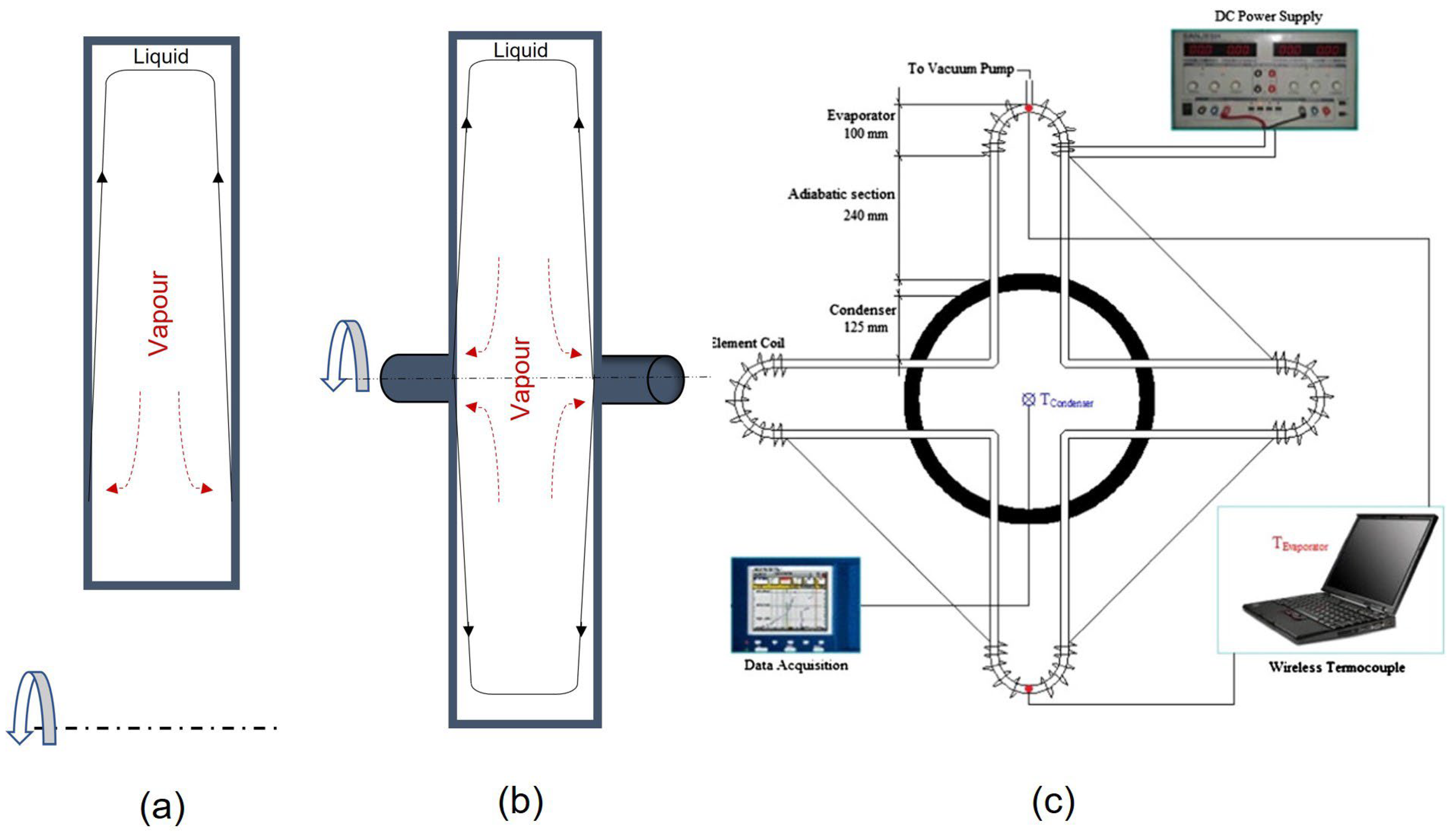
Up to now, a variety of RRHPs has been proposed for various applications. One simple arrangement is the conventional straight RRHP. As shown in
Figure 1a, such an RRHP is similar to a gravity-assisted closed two-phase thermosyphon, but with the evaporator section now located at the outer radial end of the pipe and the rotational forces helping to return the condensate along the wall of the cylinder. The same three-phase change mechanisms found in the gravity-assisted two-phase closed thermosyphon are expected to be presented in the RRHP, namely, condensation along the wall of the condenser section and surface evaporation and boiling in the evaporator section. The wall condensation in the condenser has been widely modeled as film condensation; therefore, the film thickness and temperature drop across the film are key factors concerning the condenser heat transfer [
14]. Compared to the gravity-assisted thermosyphon, the liquid film may be thinner and more non-uniform in an RRHP due to the effects of rotational forces.
A variant of the conventional RRHP is a disk-shaped rotating heat pipe (DSRHP). This is usually a partially filled rotating hollow disk (
Figure 1b) and has been proposed for the cooling of motor rotors [
15,
17]. Compared with the straight RRHP, the condensate also flows radially outward to the DSRHPs evaporator due to centrifugal acceleration, but there is a strong relative motion between the rotating wall and the returned condensate. This implies that the fluid and heat transfer mechanisms within the DSRHP are different from those in the standard cylindrical arrangement, with convection and conduction heat transfer within the liquid film being dominant while boiling heat transfer is suppressed.
In recent decades, flower-shaped rotating closed-loop pulsating heat pipes (RCLPHP,
Figure 1c) have been proposed and tested by several research groups [
16,
18,
19]. In a pulsating heat pipe, slug flow is the primary pattern [
20], while the motion of fluids is mainly driven by the pressure difference between liquid slugs and vapor slugs. For the RCLPHP tested in the above papers, the heat transfer rate was found to be positively related to the rotational speed (up to 800 rpm), which may potentially be due to the promoted condensate return brought on by centrifugal acceleration.
In the present paper, the concern is mainly with the cooling of turbine blades or disks. Therefore, the paper mainly reviews the heat transfer and operational characteristics of straight RRHPs, as they are geometrically more suited to such applications.
3. Development of the Concept of RRHP for Turbomachinery Cooling
Liquid coolants, compared with air, commonly have larger densities and thermal conductivities, as well as specific heat, leading to higher convective heat transfer coefficients. Therefore, using liquid as the coolant medium has been explored as a measure to significantly improve the convective heat transfer rate in turbine blade cooling passages, enabling gas turbines that can be designed with higher TIT. In fact, the application of a liquid-cooled turbine started very early; even one of the earliest cooled turbines was water-cooled [
21]. Much of the relevant research began around the 1940s [
22], and Schmidt [
23] proposed one of the earliest preliminary designs. Cohen and Bayley [
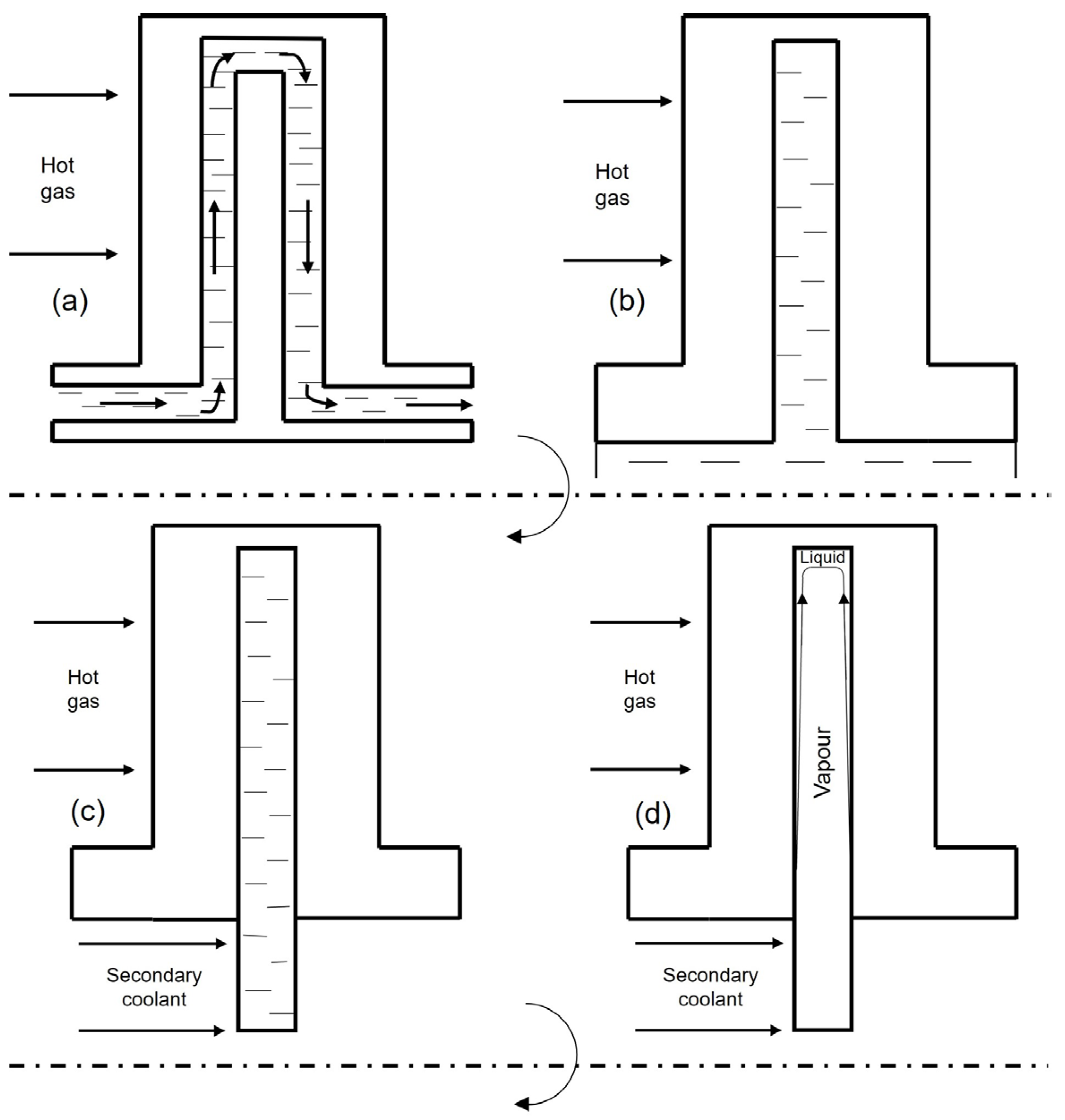
24] presented a review of the preliminary investigations regarding possible methods of liquid-cooling for gas turbine blades. The proposed internal liquid cooling methods were classified into the following four categories:
(1) Forced convection cooling: Pumping the liquid coolant to pass through the internal cooling passages and take away the heat (
Figure 2a);
(2) Single-phase open thermosyphon system: The internal channels are closed at the tip while opened at the root to allow access of liquid charged in the reservoir (
Figure 2b);
(3) Free convection closed thermosyphon cooling: Employing closed single-phase thermosyphons to absorb heat from the blade walls and simultaneously releasing heat through the secondary coolant flow passing the blade root (
Figure 2c);
(4) Two-phase closed thermosyphon cooling: Similar to the third configuration, but the thermosyphon is now only partially filled with liquid, and phase change can occur, allowing the latent heat to promote heat transfer (
Figure 2d).
Initially, considerable efforts were expended investigating forced convection systems. An aluminium-alloy turbine rig with blades, water-cooled by forced convection through a U-shaped internal passage, was studied in 1947 [
25]. It achieved 92 h of stable operation at a temperature of 1311 K, with a nearly uniform temperature distribution over most of the blade surface, excluding the region near the blade tip [
26,
27]. Freche and Diaguila [
28] carried out tests on a water forced convection cooling system in which the TIT reached 1422 K while the blade surface temperature was reduced to 401 K. Alpert et al. [
29,
30] reported two tests on a small gas turbine equipped with either a one-stage turbine or a three-stage turbine, respectively. The TIT for both turbines was 1223 K, and the blade surface temperatures were 588 K and 477 K, respectively. Although the endurance tests achieved over 100 h of operation, moderate leakage, and corrosion problems were observed. A more complex internal cooling arrangement with four inter-connected passages using organic liquid coolant was experimentally studied in 1965 [
31]. Experimental results showed that the location of the four passages could be arranged to keep the internal blade temperature difference within a tolerable limit. However, the difficulty of designing a suitable continuous flow circuit within the narrow blade interior limits the development of forced convection cooling in more general cases [
24]. In addition, forced convective liquid-cooled blades require external power to maintain the coolant circulation, implying the overall thermal efficiency is reduced. Japikse [
32] also concluded that the large quantities of water required for holding the desired temperature would constitute a severe cycle penalty for any practical system. He also pointed out that although the liquid cooling rigs show cooling performance advantages, they rarely claim an overall cost reduction compared with air cooling systems due to the complexity of the design in order to minimize leakage and corrosion.
Schmidt [
23] built up an open thermosyphon-cooled turbine employing water as the coolant in 1951. The TIT achieved 1473 K, and the average blade surface temperature was kept at 873–1073 K. Freche and Diaguila [
28] tested a single-stage turbine rotor cooled by open thermosyphons. The turbine was operating at the maximum gas temperature of 1223 K and average blade temperature of 449 K. However, the temperature distribution over the blade surface was quite non-uniform, as the maximum blade surface temperature was observed at the trailing edge with the value of 738 K. In addition, considerable difficulty was experienced with leakage of the rotor coolant. A further problem with the open thermosyphon cooling method is the difficulty of avoiding the invasion of foreign matter into the holes and the subsequent blockage failure.
Closed thermosyphons or heat pipes avoid the coolant leakage and foreign matter invasion that frequently occur in forced convection and open systems. Closed systems also allow a wider choice of primary coolants [
33] and therefore appear to be more attractive. Cohen’s review [
24] concluded that closed systems are more desirable for practical gas turbine applications due to the above advantages. In 1979, Fossen and Stepka [
34] reviewed the investigations of forced convection and open and closed thermosyphons for turbine blade cooling. For thermosyphon systems, they concluded that the relevant experimental studies involved rotating rigs as well as tilted thermosyphons. For a rotating boiling open thermosyphon system, very large heat transfer coefficients were observed, but the critical heat flux was lower than that for pool boiling. Fossen and Stepka [
34] also concluded that the influences of centrifugal and Coriolis force on flow and heat transfer were not well understood and needed to be further examined.
Developments in liquid metal research solved the corrosion and wettability problems associated with using them within heat pipes. This permitted the application of alkali liquid metals in high-temperature heat pipes to utilize their high heat of vaporization during long-term operation, allowing thousands of operation hours at 1767 K [
35]. Since then, concepts of heat pipe-cooled turbine blades have been tested in actual applications, and some test rigs have been constructed, as illustrated in the following paragraphs.
Colclough et al. [
36] constructed and tested a turbine cooled by simple closed thermosyphons, which were charged with NaK. The heat was taken away via forced convection water flow at the blade root, and no leakage problem was reported. The experiment was thermodynamically successful. However, the employment of simple thermosyphons also led to thickened trailing edges.
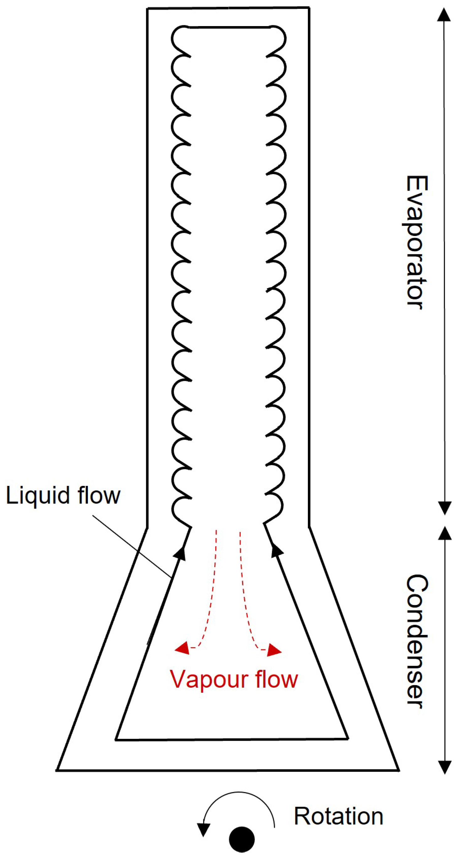
Townsend et al. [
37,
38] proposed a novel RRHP working at a temperature close to that in practical gas turbine engines. They partially filled a hollow turbine blade with potassium and employed a novel surface structure called a return-flow cascade (
Figure 3) on the inner evaporator wall to improve boiling heat transfer. When the rotational speed increased from 660 rpm to 840 rpm, the average blade surface reduced from 977 K to 797 K, illustrating the principle that increased centrifugal acceleration promotes fluid recirculation within the blade and thereby enhances heat transfer. Additionally, the condenser at the blade root experienced a rise in temperature as the result of increasing rpm, leading to a more uniform temperature distribution. The authors also commented that with their arrangement, the condenser section could be moved to below the blade root, potentially allowing further optimization of its geometry.
Cao and Ling [
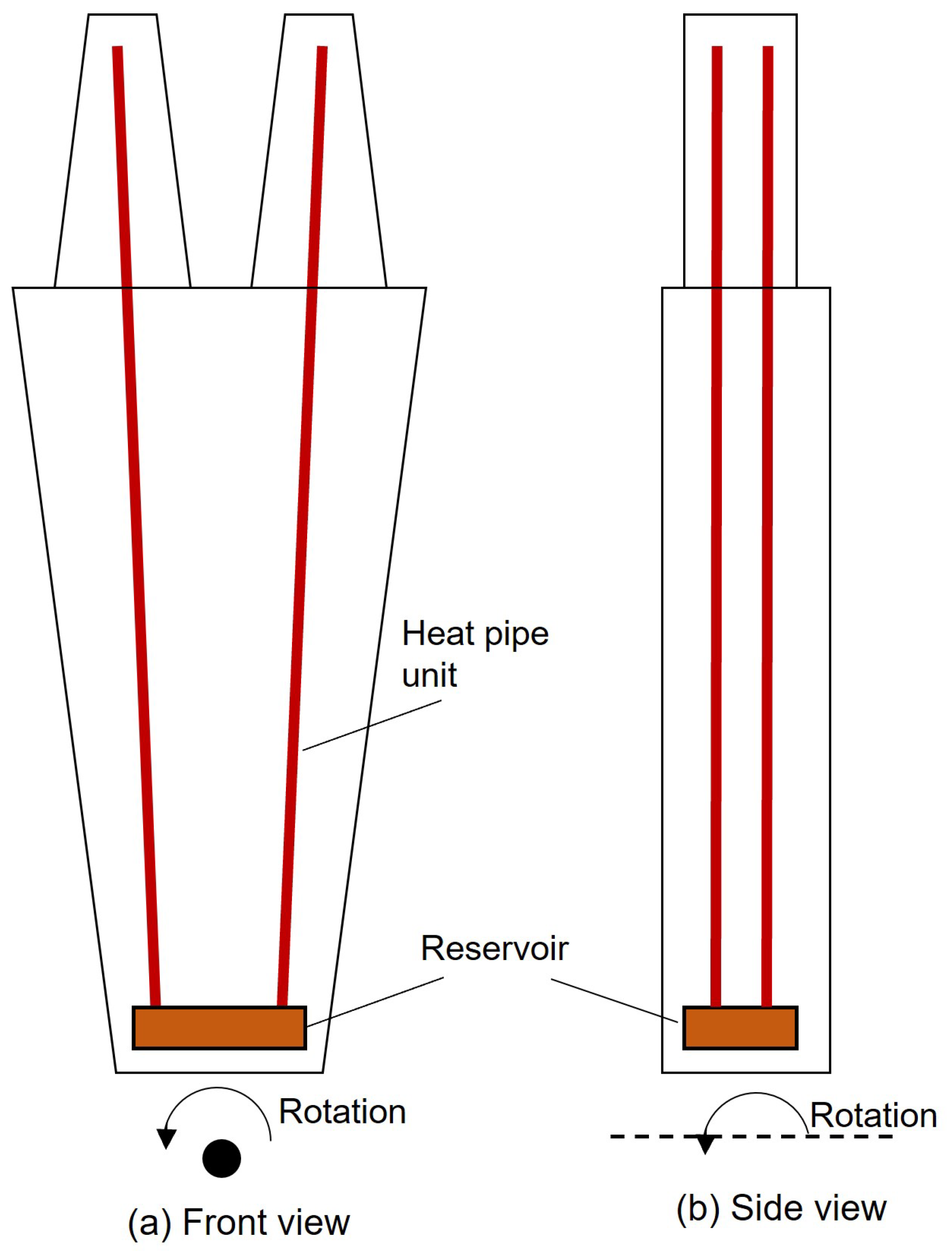
39] numerically simulated the temperature field of a 3D turbine disk operating with and without heat pipes. The simulation model consisted of a combined air and heat pipe-cooled disk with 60 blades on the top. The air cooling was modeled via a simple single channel running through the blade and part of the disk. Heat pipes were simplified as solid rods with thermal conductivity ranging from 10 to 50 kW/m/K, arranged circumferentially, and extended in the radial direction. The TIT was 1700 K. They fixed the distance between the top of the heat pipes and the disk rim while extending the pipe length radially inward to the disk center. With increasing heat pipe length, the disk rim temperature experienced significant reductions, achieving 100 K when the dimensionless pipe length (pipe length/disk radius) reached 0.4. Following this, Cao et al. [
40] proposed a new design of a heat pipe-cooled turbine disk, using multiple heat pipes interconnected by a reservoir mounted near the disk’s inner rim, as shown in
Figure 4. This design interconnects four single heat pipes to reduce the processing and fluid filling cost and, subsequently, the cost of fabrication. The RRHPs tested showed an improved heat transfer capability 17 times higher than that of solid shell materials. To further improve the heat transfer and reduce blade surface temperature, Reding and Cao [
41] experimentally tested another configuration based on the earlier arrangement shown in
Figure 4 but moved the reservoir from the disk inner rim to the blade interior. In other words, in this new design, the two RRHPs shown associated with each blade were interconnected within the blade interiors. This modification increases the contact area between the blade’s inner surfaces and the working liquid, as well as increasing the maximum volume of the working fluid charged. As the rotational speed increased from 900 to 2700 rpm, significant heat transfer enhancement was observed from the modified design. The best heat transfer performance was found when the reservoirs were fully filled.
Cao [
3] summarised the published works between 1998 and 2007 for liquid metal-charged RRHPs proposed for gas turbine cooling. He concluded that high-temperature RRHPs could result in very high heat transfer performance, with low fabrication cost and impressive reliability.
4. Heat Transfer of the RRHP
4.1. Factors That Influence Heat Transfer
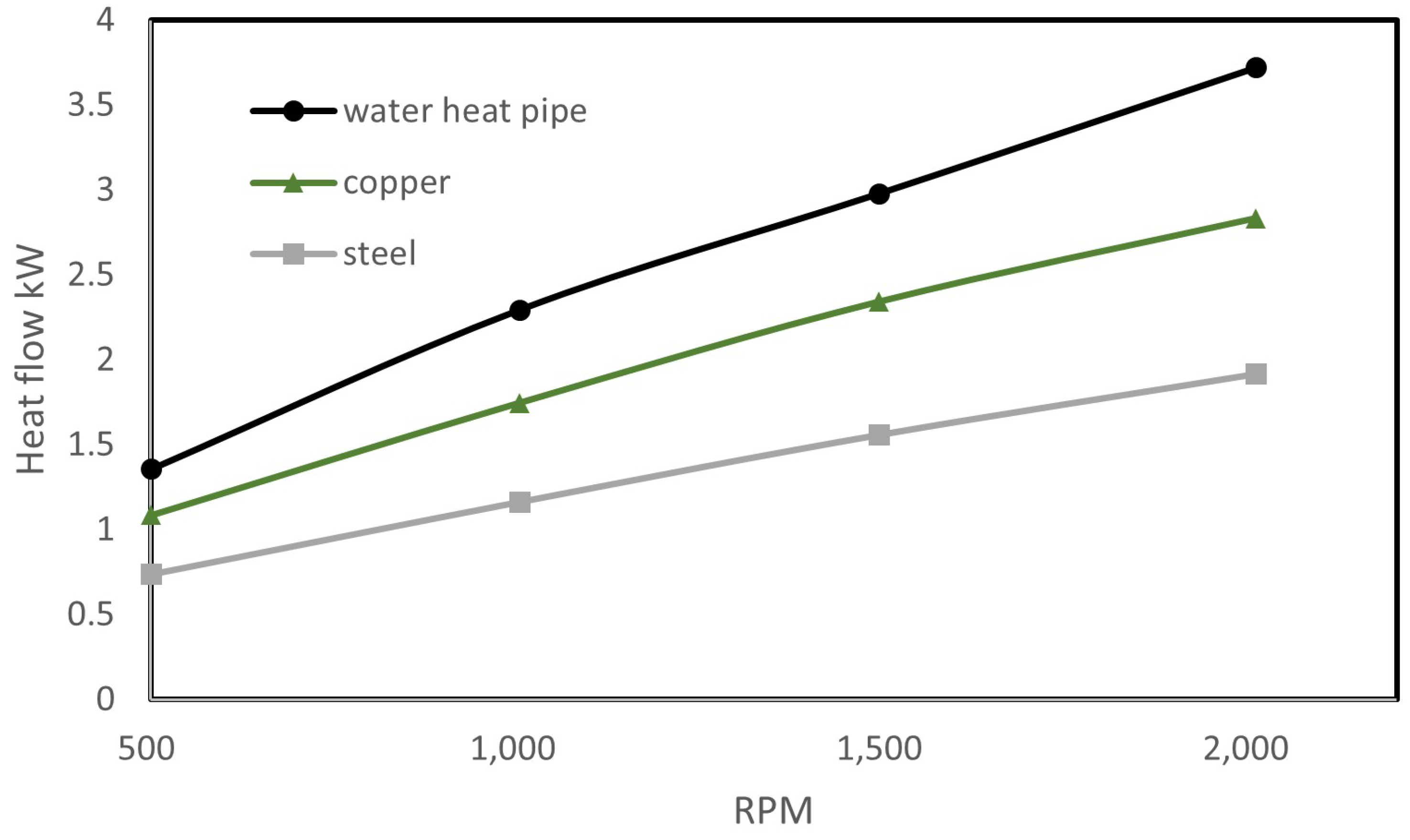
Cohen and Bayley [
24] built a test rig consisting of a rotating wheel mounted with a row of steel RRHPs. The outer halves of the RRHPs were heated by hot gas, while the inner halves were cooled by unheated airflow. The heat pipes were partially charged with water and other organic fluids, while the temperature rise of the cool airflow, and its flow rate, were recorded as a measure of heat flow. Water gave the best heat transport performance because of its high latent heat of vaporization compared with the other organic fluids tested. As shown in
Figure 5, it was found that the water-charged RRHPs showed substantial improvement in heat transfer ability vis-à-vis solid metal rods. Furthermore, the heat transfer rate of RRHPs was positively correlated with the increasing rotational speed (from 500 to 2000 rpm). When varying the fill ratio from 1.5% to 55%, no significant change in heat transfer was observed.
Ling et al. [
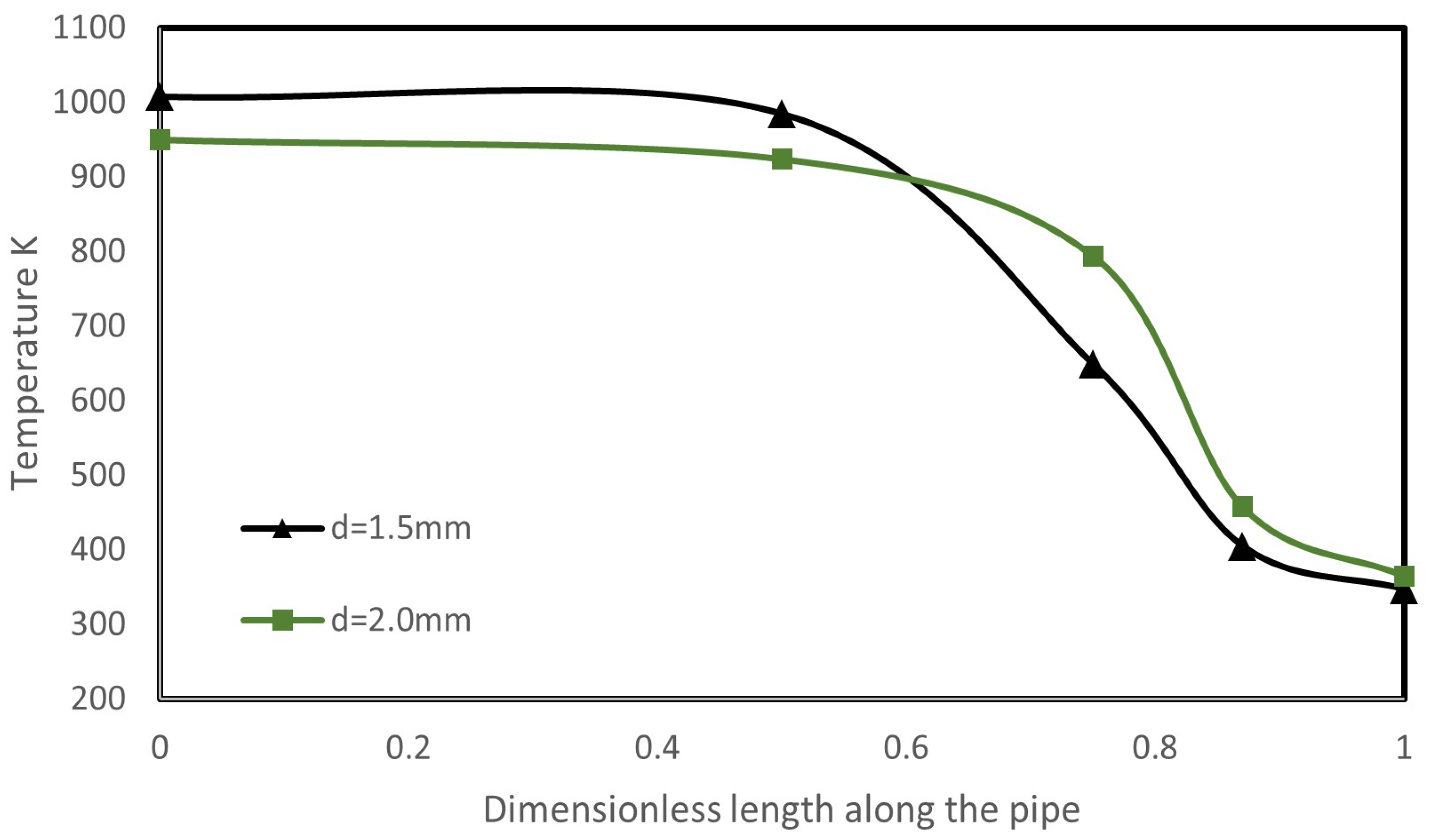
14] tested a sodium-charged RRHP operating at a maximum temperature between 1073.15 and 1123.15 K and a rotational speed up to 3600 rpm. The RRHP container was fabricated of 304 W steel. The outer half tube was heated (up to 300 W), and the inner half was cooled by air. The RRHP built showed very large thermal conductivity 60–100 times higher than that of copper. It was observed that, with increasing heat input, the temperature profiles along the tube became relatively uniform, implying a smaller overall thermal resistance. Additionally, it was observed that increasing the centrifugal acceleration led to a larger temperature gradient and vapor pressure drop along the pipe. Finally, a decrease in pipe diameter raised the evaporator temperature as well as the temperature gradient along the pipe, as shown in
Figure 6, implying an increase in overall thermal resistance. The authors explain that this was due to the increased pressure drop caused by the reduction in the pipe cross-section area. The pressure of the evaporator was thereby increased, leading to a higher saturation temperature by which the evaporator temperature increased. In addition, the increased pressure drop accelerated the vapor flow, leading to a larger interfacial frictional force between the liquid and vapor phases, which also contributed to the steeper temperature profile.
Maezawa et al. [
42] reported an experimental study focusing on the performance of the condenser in cylindrical RRHPs charged with HCFC-142b. The experimental results showed that the condenser thermal resistance reduced with increasing rotational speed, while the evaporator thermal resistance stayed almost constant above a certain rotational speed. According to the measured heat transfer coefficients, and with the assumption that the inner condenser wall was covered by a very thin layer of condensate, the authors derived the following two semi-empirical correlations for two-dimensional condenser heat transfer, applicable to centrifugal force dominated and Coriolis forced dominated regions, respectively:
In Equations (1) and (2) it can be seen that the heat transfer of an RRHP is affected by several dimensionless parameters, including Archimedes number
, Prandtl number
, Jacob number
, length/diameter ratio
, as well as Ekman number
when the Coriolis force
is larger than the centrifugal force
. It can be seen that the heat transfer rate of the condenser of an RRHP is positively related with
,
,
, and inversely related with
and
. These dimensionless parameters have also been adopted in other literature [
43] for evaluating the heat transfer of RRHPs.
Waowaew et al. [
43] investigated the evaporator of cylindrical RRHPs partially filled with various working fluids using a rig similar to the one built in [
42] but now set up to study the evaporator. The working temperature of the RRHPs remained at 363.15 K, and the value of heat loadings used to keep this working temperature was recorded for the derivation of empirical correlations. The results illustrate that rotational acceleration promotes the heat transfer of RRHPs regardless of other factors. Tests with different working fluids showed that the heat flux was negatively correlated to increasing fluid density. The authors explained that this result was due to the reduced evaporator pressure caused by the decreased liquid density. Evaporation was thereby promoted, implying that the heat transfer was enhanced with low-density working fluids. They also concluded that with an increasing aspect ratio (
), the boiling inside the evaporator tended to approach the boiling in confined channels at which low heat flux occurs. Cao and Ling [
44] reported a similar tendency. They tested water-charged RRHPs with inner diameters varying from 1.5mm to 3mm. As the diameter was decreased whilst keeping the length constant, the vapor temperature drop along the pipe became larger, representing an increased thermal resistance. They explained that the reason was probably due to the vapor-liquid interfacial frictional forces increasing with reduced diameter, introducing additional thermal losses. Considering both results, it may be concluded that with increasing aspect ratio the thermal performance of an RRHP can be adversely affected by two mechanisms, namely, the change of boiling flow regime and the increased interfacial frictional losses.
Ling et al. [
45] derived an analytical solution related to the vapor temperature distribution along an RRHP operating at a steady state. The Reynolds number and Mach numbers,
and
, defined as
were assumed to be lower than 2300 and 0.2, respectively, implying that the vapor flow was assumed to be incompressible and laminar. In Equations (3) and (4),
,
,
,
,
,
,
, and
denote the diameter of the core vapor flow, the heat power, cross-section area of the core vapor flow, the dynamic viscosity of vapor, the latent heat of vaporization, the specific heat ratio, the vapor gas constant, and the vapor temperature, respectively. This analytical solution evaluates the temperature drops across the liquid film and along the core vapor flow. It was found that when the dimensionless centrifugal acceleration (ratio of centrifugal acceleration to gravitational acceleration) rose above 150, the temperature drop across the liquid sodium film became negligible, implying that the condenser heat transfer can be enhanced by increasing centrifugal acceleration. This is consistent with the findings by Maezawa et al. [
42]. For high rotational speed conditions that are encountered in practical gas turbines, the vapor flow temperature drops were found to be of the order of 10–40 K, which are relatively small compared with the operational temperature (1100–1500 K). The vapor flow temperature drop is mainly due to the liquid-vapor interface frictional force and centrifugal force. If the cross-sectional area of the pipe decreases, the vapor temperature drop will increase due to the stronger interfacial frictional force, leading to higher thermal losses. On the other hand, under extremely high rotational speed, the centrifugal acceleration acting on the vapor flow is opposite to the pressure gradient and may, therefore, introduce a new operational limit for the RRHP [
46].
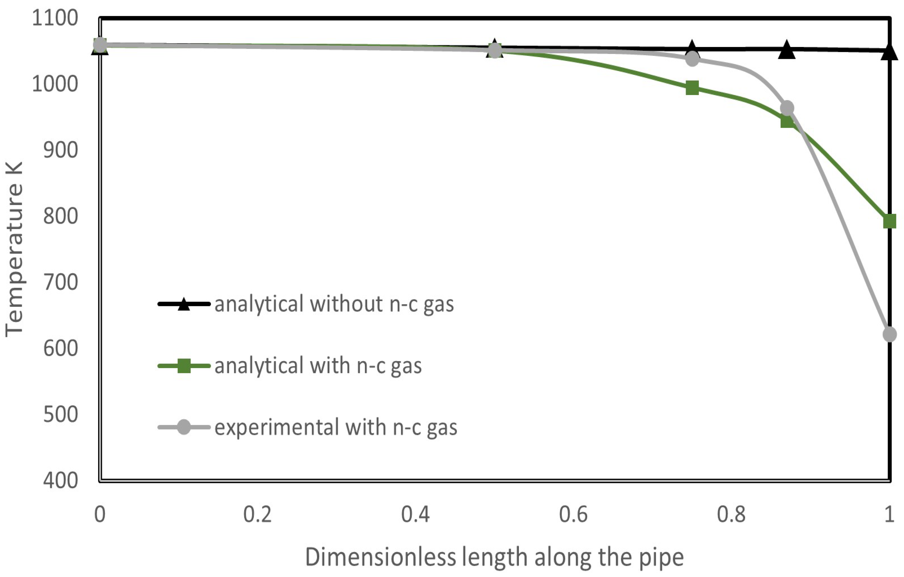
The analytical solution presented in [
45] assumed that the vapor within the RRHP was completely condensable. However, in the practical fabrication of the heat pipe, tiny amounts of non-condensable gas may be charged into the heat pipe. Therefore, ref. [
47] extended the analytical solution of [
45] by including the contribution of non-condensable gas to the vapor temperature drop. Additionally, they experimentally studied RRHPs slightly filled with non-condensable gas and predicted the temperature profile using the extended solution, assuming that 10% of the condenser length was occupied by non-condensable gas. As shown in
Figure 7, the inclusion of non-condensable gas substantially increased the vapor temperature drop along the pipe, leading to a significant deviation from the original analytical solution at the end of the condenser and substantially increasing the thermal resistance of the condenser.
4.2. Operational Limits
RRHPs operating in certain conditions may encounter limits by which their maximum heat transfer rate can be restricted [
20], and these conditions are known as operational limits. A stationary two-phase wickless heat pipe may encounter [
48] as follows:
Burn-out limit: if the liquid fully evaporates before the condensate reaches the evaporator;
Sonic limit: if the vapor speed reaches the sound speed and chokes the channel;
Entrainment (Flooding) limit: if the liquid-vapor interface shear force becomes high enough to disrupt the returning condensate back into the vapor stream, which can adversely affect the fluid recirculation and axial heat transport;
Viscous limit: occurs in liquid metal charged heat pipes when the viscous force dominates the vapor flow;
Condenser limit: maximum overall heat transfer may be restricted by the condenser’s ability to condense the vapor flow.
Cao and Chang [
46] analytically discussed the limits of RRHPs for turbomachinery applications. As shown in
Figure 8, the temperature drop across the condensate film is relatively high for RRHPs at low rotational speed, implying that under such conditions, the RRHP may be subject to sufficient condenser thermal resistance that it may encounter the condenser limit. When the rotational speed increases beyond 4000 rpm, the condenser thermal resistance is drastically reduced, and the condenser limit is thereby eliminated. However, if there is non-condensable gas in the condenser, the condenser limit may still exist, as it is known that the presence of non-condensable gas can lead to a degradation of the condenser heat transfer rate.
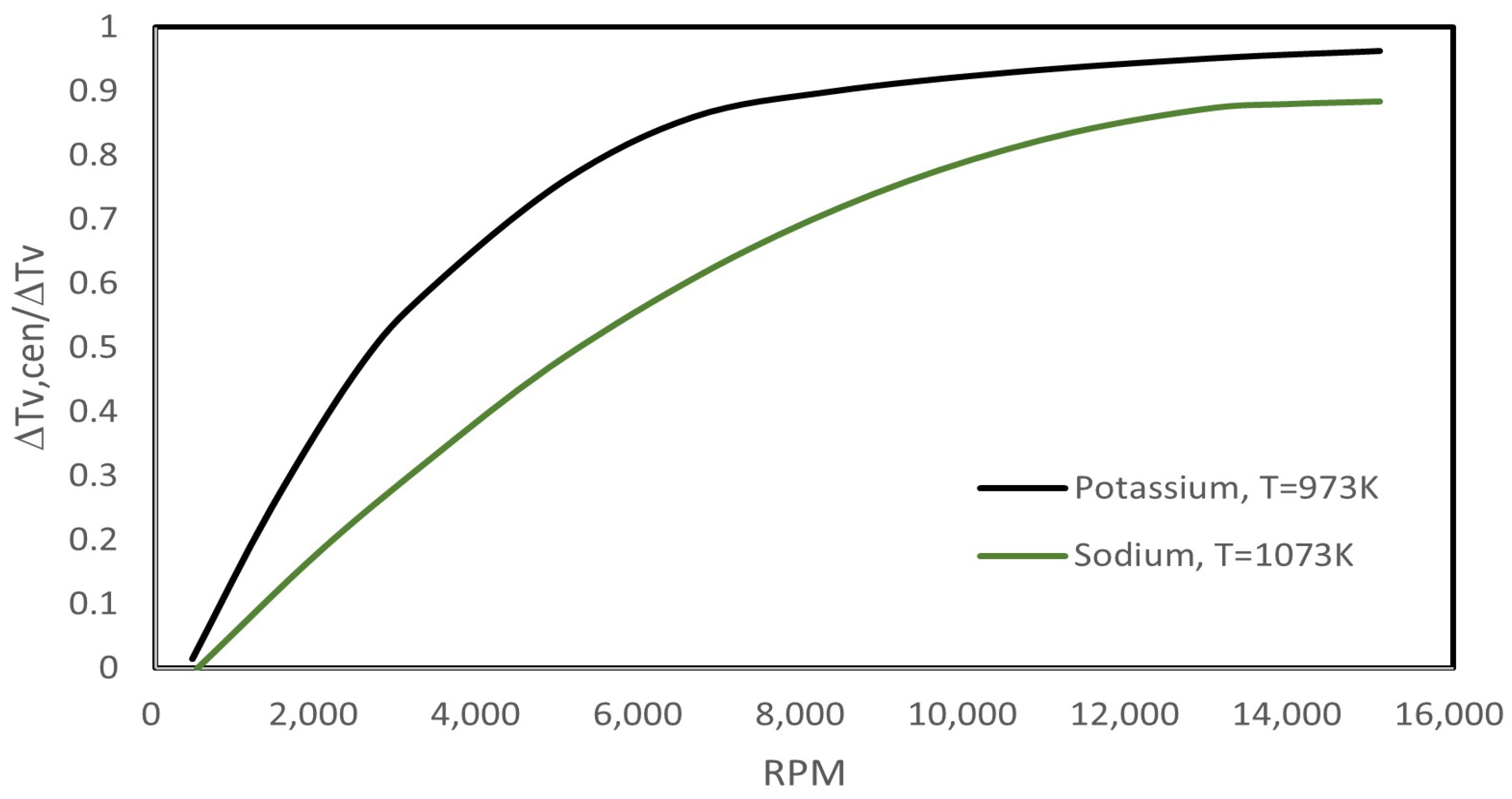
As the direction of the centrifugal force is opposite to that of the vapor pressure gradient, increasing rotational speed tends to result in a larger thermal loss in the vapor flow; therefore, RRHPs may encounter a heat transfer limit at very high rotational speeds. Cao and Chang [
46] numerically evaluated the contribution of the centrifugal force to the vapor temperature drop along the pipe. As illustrated in
Figure 9, when the rotational speed reached 14,000 rpm, approximately 90% of the vapor temperature drop was contributed by centrifugal acceleration, implying that the centrifugal force dominated the vapor flow thermal loss beyond this rotational speed. Ling et al. [
45] modeled a sodium-charged RRHP operating at various centrifugal accelerations. It was found that the vapor temperature drop along the whole pipe, as well as overall thermal resistance increased almost linearly with increasing centrifugal acceleration. However, the adverse effect of centrifugal force on vapor flow was small, even at a very high rotational speed. For the RRHP they modeled, the vapor temperature drop was approximately 20 degrees when
reached 60,000
, which was negligible compared with the working temperature (1500 K).
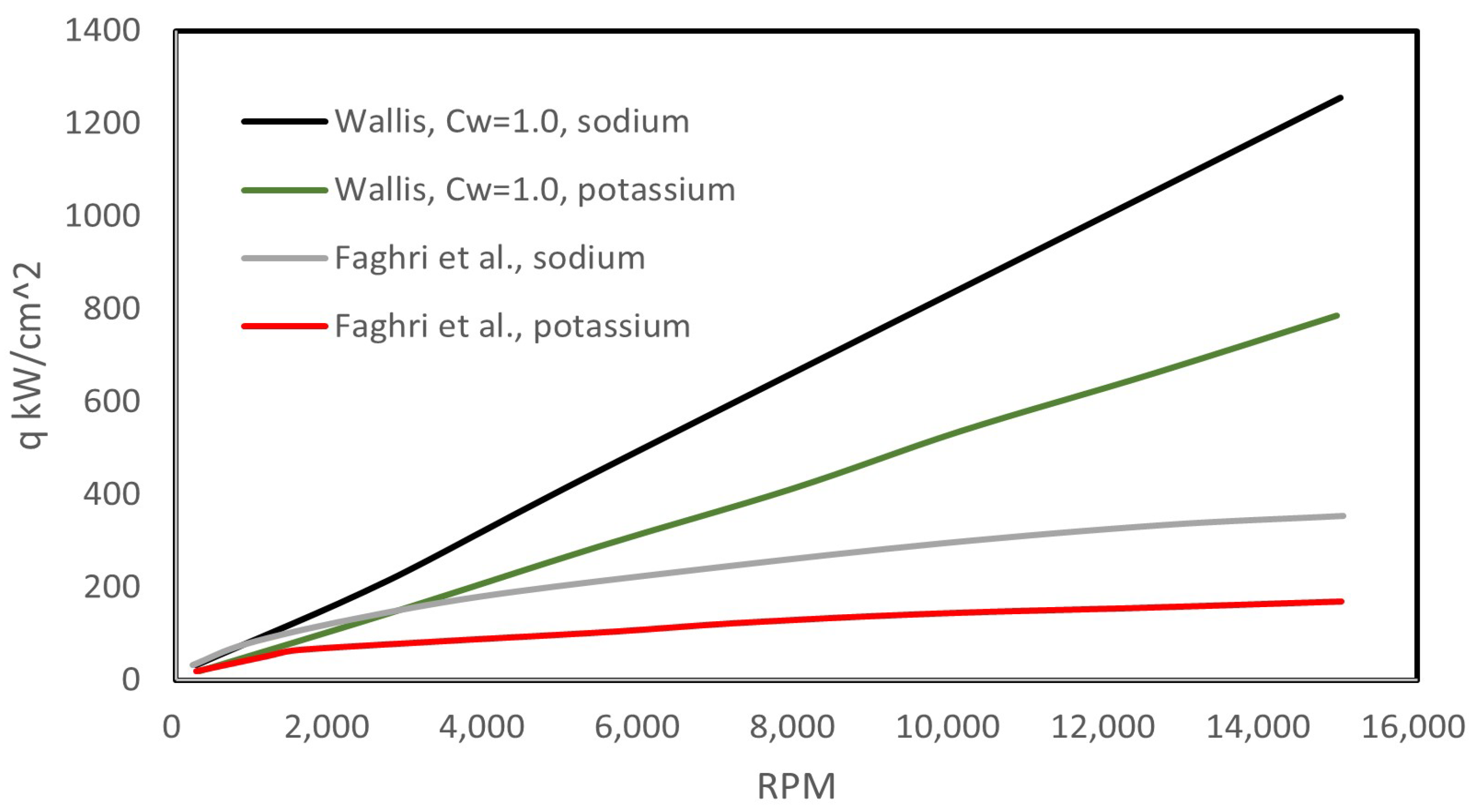
Cao and Chang [
46] also evaluated the entrainment limit of RRHPs charged with sodium and potassium based on the correlations proposed by Faghri et al. [
49] and Wallis [
48]. They used these correlations to calculate the critical heat flux of the entrainment limit, namely, the heat flux value when the vapor velocity becomes sufficiently high to hold up the returning condensate flow. As illustrated in
Figure 10, where
represents a constant in Wallis’s correlation, the two correlations do give a different rate of increase in the critical heat flux with rotational speed. However, at typical working conditions of gas turbines, both correlations result in critical heat fluxes high enough to be acceptable for such applications. Therefore, the entrainment limit of liquid metal RRHPs appears not to be a major concern in turbomachinery applications.
Cao et al. [
14] tested an RRHP with increasing heat inputs while keeping other factors constant. The condenser temperature profile always appeared to be linear until the heat input reached and exceeded 300 W, after which the vapor temperature profiles along the condenser exhibited an increase followed by a sharp drop near the condenser end. It was explained that the high heat input greatly promoted evaporation, leading to a higher vapor velocity by which the sonic limit was encountered, with the vapor flow choked at the position where the vapor temperature peaked.
4.3. Summary
While a number of studies have concentrated on the heat transfer characteristics and operation limits of RRHPs, researchers have constructed and tested RRHP rigs that operate at, or close to, the practical working temperatures. Furthermore, modeling approaches have been adopted to examine the heat transfer and operational limits under conditions that were difficult to achieve in the laboratory. The main findings were as follows:
(a) RRHPs have shown effective cooling performance at high working temperatures and moderate rotational speeds. Sodium and potassium have been considered suitable working fluids for RRHPs that are proposed for turbomachinery applications.
(b) A variety of factors can affect the heat transfer rate of an RRHP, including pipe aspect ratio, rotational speed, inner diameter, and working fluid density. Increasing rotational speed can result in a higher condenser Nusselt number due to thinner condensate film and a higher heat transfer rate in the evaporator. Although the centrifugal acceleration can also adversely affect the vapor flow within an RRHP, the magnitude is small even at very high centrifugal accelerations. Increasing the density of working fluids appears to have adverse effects on the heat transfer of the evaporator. The aspect ratio influences the heat transfer rate of an RRHP in the following different ways: it is positively related to the Nusselt number of the condenser but shows a negative relationship with the thermal resistance of the evaporator.
(c) The vapor temperature drop along the pipe is mainly due to the centrifugal force and vapor-liquid interfacial frictional force. In addition, if non-condensable gas is present in the pipe, it will substantially reduce the cooling ability at the end of the condenser, leading to a substantial temperature drop along the heat pipe and, subsequently, a reduction in the overall heat transfer rate.
(d) The entrainment limit appears not to be a concern for high-speed RRHPs, as the rotation can remove the condenser limit that may be encountered in stationary heat pipes. On the other hand, centrifugal acceleration dominates the vapor thermal loss at a high rotational speed.
5. Secondary Flow Effects
Heat transfer is a side effect of fluid motion. One of the main differences between an RRHP and a conventional thermosyphon is the radial fluid recirculation due to orthogonal rotation. From the foregoing studies, it can be seen that centrifugal acceleration has been proven to have a positive effect on heat transfer. Furthermore, Coriolis force is no longer negligible when the RRHP is operating at high rotational speed and can lead to secondary flow that will influence the heat transfer. To further understand the heat transfer of an RRHP, it is necessary to understand the rotational effects on the fluid dynamic profiles within the RRHPs. In this section, the open literature is briefly reviewed and discussed with a view to delineate the primary aspects related to secondary flow-induced heat transfer.
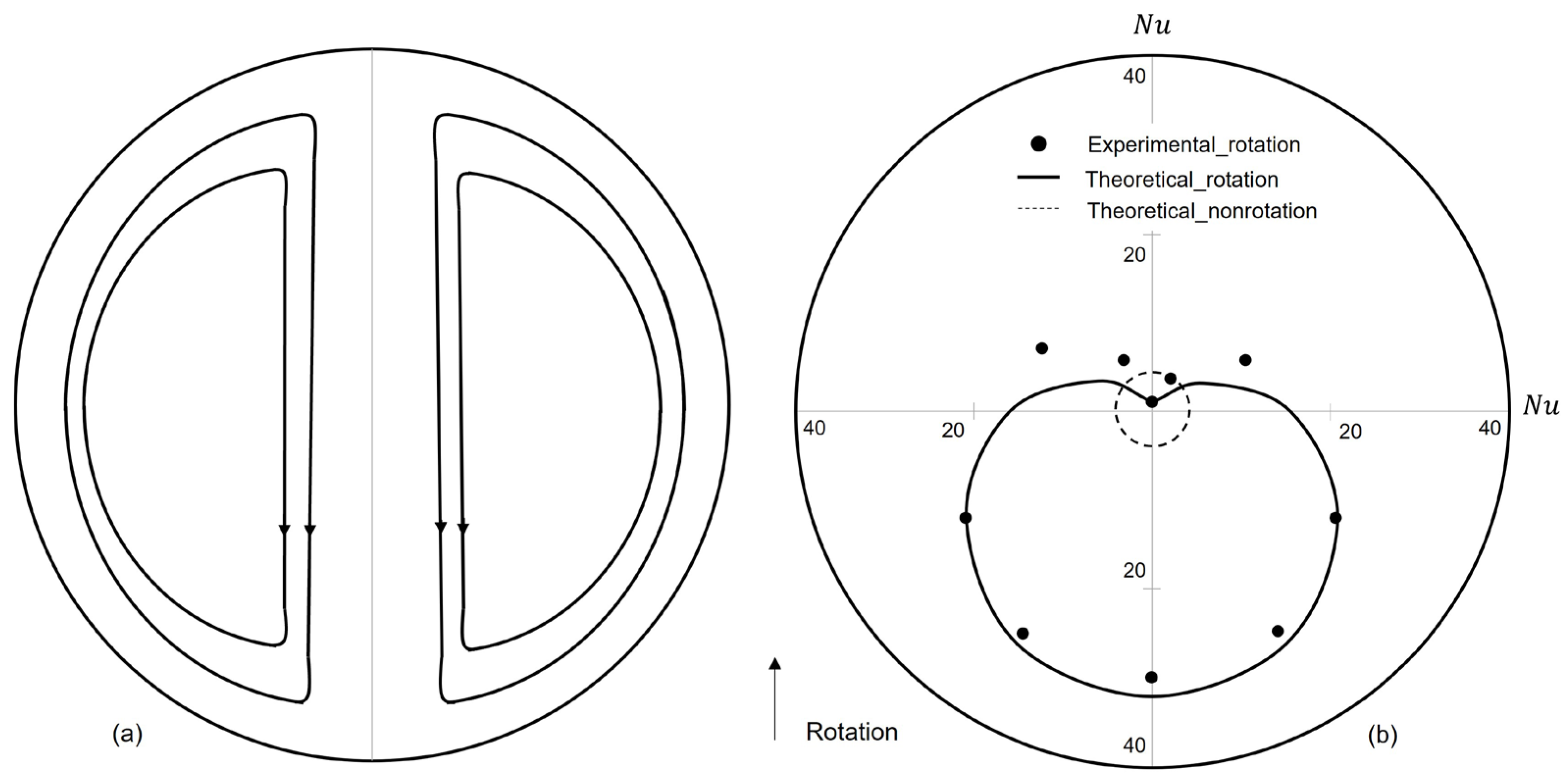
Mori et al. [
50] theoretically and experimentally studied the forced convective heat transfer of rotating pipe flow. The pipe was rotating around an axis perpendicular to the pipe axis, and the fully developed flow region was investigated. The secondary flow is schematically illustrated in
Figure 11a. For laminar flow conditions, the secondary flow causes a non-uniform circumferential distribution of local Nusselt number, and the mean convective heat transfer is thereby significantly enhanced. The maximum Nusselt number was found at the stagnation point of the secondary flow, which occurs on the trailing side of the rotating tube, as illustrated in
Figure 11b. Siegel [
51] reported similar conclusions for the laminar condition. He concluded that the secondary flow induced by the Coriolis force always tends to increase the heat transfer coefficient for both inward-directed and outward-directed pipe flows. Mori et al. [
50] also investigated the heat transfer of the fully developed turbulent flow in a radial rotating pipe. Although the local Nusselt number slightly increased at the stagnation point, and the mean Nusselt number experienced an increase of more than 10% (at 1000 rpm) compared with that found in a stationary pipe turbulent flow, the improvement in convective heat transfer was not considerable compared to that found in laminar flow. Morris and Salemi [
52] reported an experimental study on the heat transfer of smooth circular tubes that rotate in the orthogonal mode. They also observed an enhancement in heat transfer on the trailing side of the tubes compared to the leading side.
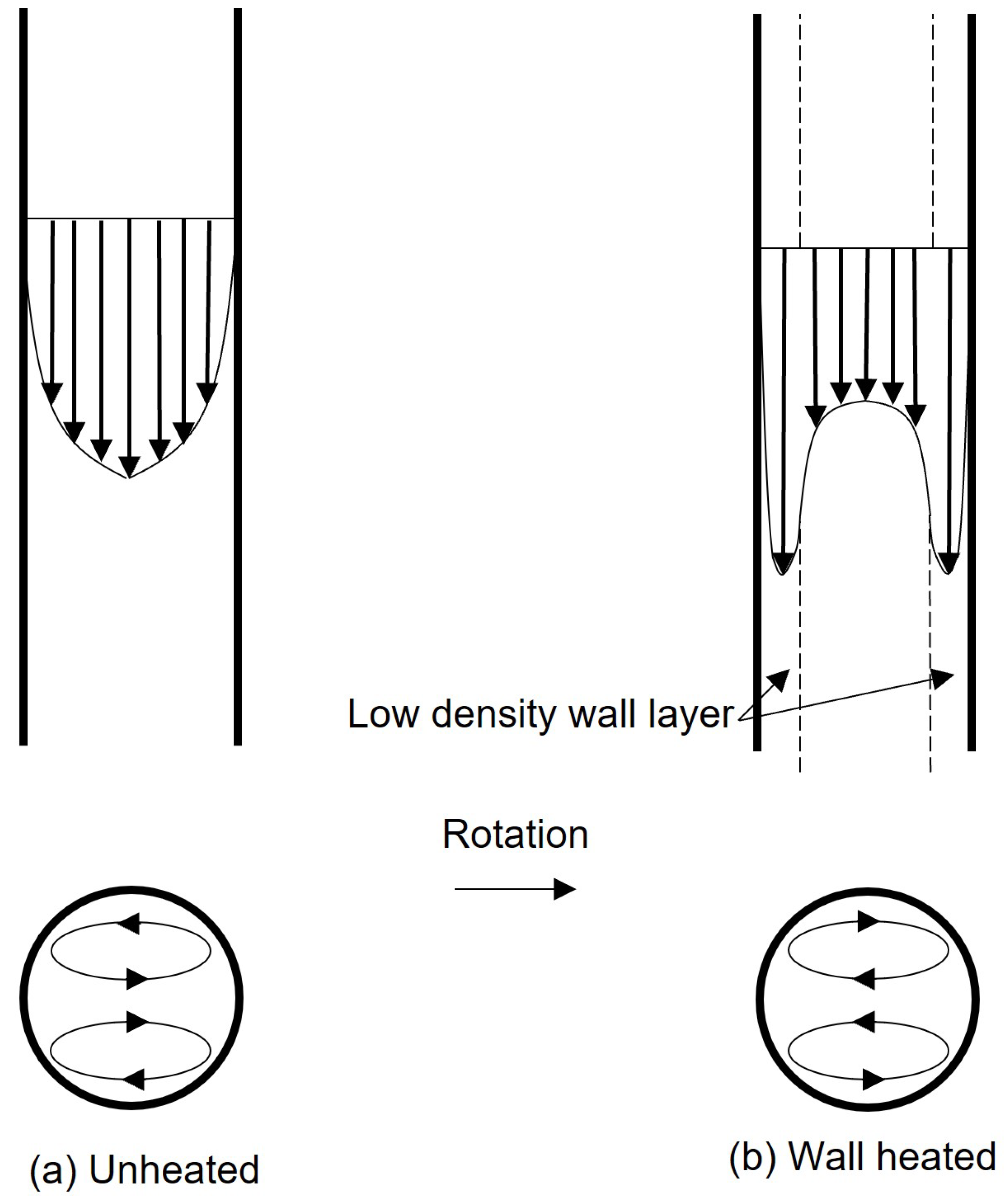
El-Masri and Louis [
53] investigated the secondary flow effects inside an inward-directed round pipe flow. As shown in
Figure 12a, in an unheated inward-directed rotating pipe flow, the double helix secondary flow was generated as the result of rotation, as would be expected from the studies mentioned above. On the other hand, when the pipe wall was heated to a high temperature, a different pattern was seen. In this case, a low-density wall layer of fluid is generated, as illustrated in
Figure 12b. As a result, a significant centrifugal buoyant force
appears and drives this layer at a higher speed than the main flow, tending to create a secondary flow opposite in sense to that shown in
Figure 12a. In this situation, it is the Coriolis force that drives the secondary flow, which tends to promote the mixing between the cold core flow and the wall layer. Of course, if the pipe wall is heated, but its rotational speed,
, is only small, then the centrifugal buoyancy
will be weak, and the secondary flow pattern will still resemble that shown in
Figure 12a. El-Masri and Louis [
53] found that when increasing the rotational speed from 1000 rpm, the secondary flow pattern tended to develop from that shown in
Figure 12a to that of
Figure 12b. In this transition stage, the mixing effect was attenuated. Once the rotational speed reached a certain value, the flow circulation pattern of
Figure 12b became dominant, and then the secondary flow mixing was strengthened with further increases in the rotational speed, a condition referred to as the “fully developed mixing zone”.
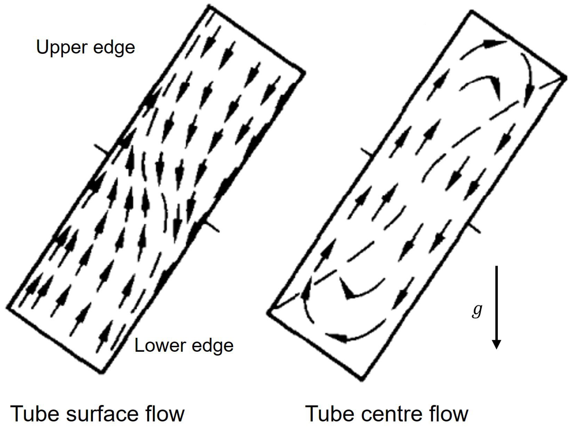
For an RRHP or single-phase rotating thermosyphon, the working fluid is sealed in an enclosed pipe; therefore, fluid motion does not have sufficient distance to fully develop, and the behavior observed may be somewhat different from that described above. Moreover, the main fluid motion is mainly driven by buoyancy forces rather than external forces. To study the effect of secondary flow on RRHPs, some researchers started with investigations of inclined thermosyphons while postulating that the tangential component of gravitational force could be an analogy to Coriolis force. Japikse et al. [
54] experimentally investigated a tilted single-phase water-charged thermosyphon. It was found that the inclination tends to accelerate the stream from the lower boundary layer into the upper core along the upper edge and an analogous but opposite effect on the lower edge (
Figure 13), similar to the flow patterns observed by Martin and Lockwood [
55] in the inclined open thermosyphon. The mixing between the cold core and hot core, and associated heat transfer rates, were thereby found to be promoted with increasing tilt angle (
Figure 14).
However, Lock and Zhao [
56] pointed out that the analogy between Coriolis force effects and a tilted thermosyphon is not correct. The Coriolis forces in a rotating system are independent of the temperature field, while lateral buoyancy forces in a stationary system are not. They reported a numerical study on a single-phase radial rotating thermosyphon in the shape of a rectangular cavity with a length/width ratio of 5. The cavity was horizontally placed, rotating around a vertical axis. The fluid was assumed to be viscous and incompressible, and the flow was laminar and subject to the Boussinesq approximation. The Rayleigh number was kept at very low values (10
4 ~ 10
5) to allow the thermosyphon to operate between the upper limit of the conduction regime and the lower limit of the boundary layer regime. In particular, the role of Coriolis force effects was investigated at low rotational speeds. It was found that at such speeds, the Ekman layers, located at the upper and lower surfaces of the cavity, improved the heat transfer rates in what has been called the Coriolis-enhanced regime. Compared with stationary tilted systems, the rotating system tended to flatten the velocity profiles at each cross-section.
For RRHPs with interfacial interactions and phase change processes, the secondary flow issues would be more complicated than those in the single-phase situations described above. In the evaporator section, the wall super heat, wall heat flux partition, bubble nucleation frequency, departure size, and frequency may be affected by the secondary flow, leading to increased or decreased thermal resistance. On the other hand, the Coriolis force may influence the distribution, as well as the Reynolds number, of the liquid film within both the condenser and adiabatic sections. Understanding these fundamental problems related to secondary flow effects is essential for the design and development of RRHPs and requires further study.
In summary, in forced convection rotating pipe flow, the Coriolis force generates secondary flow, which can contribute to the mixing between the cold central region and the hot near wall region. On the other hand, in a more strongly heated rotating pipe flow, the Coriolis force induces a secondary flow that is not simply linearly related to the increasing rotational speed. Only when the rotational speed exceeds a certain value does the intensity of the secondary flow become positively correlated to increasing rotational speed. Inclination can also induce secondary flow to promote heat transfer rates in a closed thermosyphon; however, it leads to gross error if this is used as an analogy for the Coriolis force influences. The effects of secondary flow on RRHPs still need further investigation.
6. Numerical Simulation of Mass Transfer
Recently, the development of computational fluid dynamics (CFD) has provided a much-needed additional capability concerning the investigation of multiphase flow. CFD has been commonly employed to investigate the thermophysical features, as well as fluid dynamic features, of stationary two-phase closed thermosyphons. Yao et al. [
57] summarised the relevant numerical studies that have taken place in recent years. Most computational studies on two-phase closed thermosyphons have employed volume of fluid (VOF) approaches to capture the liquid-vapor interfaces.
For the modeling of evaporation/boiling and condensation within heat pipe modeling approaches can generally be categorized into the following three primary methods: the Rankine–Hugoniot jump condition [
58], the Schrage model [
59], and the Lee model [
60]. The Rankine–Hugoniot jump condition evaluates the interfacial mass transfer by calculating the net energy transport across the liquid-vapor interfaces. The energy transport across the interface is considered mainly due to conduction; therefore, the mass transfer rate across the interface is driven by temperature gradient differences and is expressed as follows:
where
,
,
, and
represent the unit vector normal to the liquid-vapor interface, thermal conductivity, temperature gradient, and the latent heat of vaporization, respectively. Subscripts
and
denote liquid and vapor phases.
The Schrage model uses the kinetic theory of gases to relate the flux of molecules that are crossing the liquid-vapor interface with the temperature and pressure fields. Therefore, the mass transfer rate can be calculated by the following:
where
represents the ratio between the number of molecules transferred to the other phase and the number of molecules that escaped from the original phase,
is molecular weight, and
is pressure. It can be noticed that both of the above-mentioned models require a pre-existing liquid-vapor interface to be present and, therefore, are suitable for the modeling of nucleate boiling, film boiling, film condensation, surface evaporation, and surface condensation. Other versions of these two models have been reviewed by Kharangate and Mudawar [
61].
Compared with the simulation of axially rotating heat pipes, where both evaporation and condensation do occur principally at the liquid-vapor interfaces [
13], the phase change processes within two-phase closed thermosyphons primarily occur within the saturated phases. Therefore, the Lee model of phase change mass transfer is usually taken to be the most suitable model for the simulation of phase change processes within two-phase closed thermosyphons, and similarly for RRHPs. This model assumes the mass transfer is primarily due to the deviation of the local temperature from the saturation temperature and can be expressed, as in the following:
where
and
are the phase change time relaxation factors expressed as follows:
In Equations (9) and (10),
is Sauter mean diameter of bubbles. The inclusion of
in the above expressions may cause practical difficulties in a simulation since accurate estimates for it are unlikely to be available. For practical implementation, Lee recommended 0.1 for the values of both
and
. However, researchers have used a wide range of values, from 0.1 to
[
61]. For the simulation of two-phase closed thermosyphons, the following variety of approaches to determine
and
have been proposed and implemented: Kafeel and Turan [
7,
62] used 0.1 for
, while dynamically adjusting
according to the overall mass balance within the thermosyphon; Xu et al. [
63] extended the foregoing approach by modifying
and
simultaneously to keep the mass balance within the thermosyphon; some researchers manually tune the values of both coefficients to minimize the interface temperature’s deviation from the saturation temperature or simply adopt whatever default values are provided in commercial codes.
It can be seen that choosing appropriate values for and can be a difficult problem in the simulation of stationary two-phase closed thermosyphon behavior. It could prove to be even more challenging when simulating the RRHP using similar approaches. This is due to the fact that fluid dynamic processes within the RRHP are significantly different from those in the stationary thermosyphon, including, for instance, the effects of secondary flow on wall superheat, wall heat flux partition, and bubble nucleation parameters. However, these differences are not explicitly accounted for in Equations (7)–(10), implying that further refinements in the modeling might be needed. This may also be one reason why CFD modeling of the RRHP has rarely been reported.
7. Conclusions and Recommendations
In this paper, the historical development of liquid-cooled turbine blades, efforts to develop and adapt rotating heat pipes for blade cooling, and numerical models for rotating heat pipes have been reviewed. In past decades, a series of experimental studies have proved the possibility of employing rotating heat pipes in gas turbine assemblies, and several modeling studies have been extended to develop prediction methods for heat pipes.
Based on the foregoing experimental and modeling studies, the centrifugal force was considered to be the dominant factor that positively influences the heat transfer of RRHPs. Other key factors include aspect ratio, inner diameter, and working fluid. As long as within a certain range, the fill ratio has not been reported as having any significant influence. Thermal losses of the vapor flow within an RRHP are primarily due to centrifugal acceleration and liquid-vapor interfacial frictional forces, with the former dominating at high rotational speeds. Some of the operational limits that may be encountered in a stationary heat pipe can be eliminated in a high-speed RRHP. On the other hand, the thermal loss due to centrifugal forces may become substantial at a high rotational speed. In rotating radial pipe flow, the Coriolis force has been proven always helpful in enhancing heat transfer. However, the effect of Coriolis force within a rotating enclosed cavity is different from that in forced convection pipe flow, resulting in more complex effects of it on heat transfer rates. A number of CFD approaches have been reasonably successfully adopted for simulating stationary two-phase closed thermosyphons. However, the CFD simulation of RRHPs has rarely been reported, due at least in part to the lack of relevant suitable mass transfer modeling methods.
From the foregoing literature, it can be seen that although the modeling studies predicted the temperature profile well vis-à-vis measured values in experiments, the comparisons are restricted to moderate rotational speed and TITs, which are still relatively low compared with actual gas turbines. Therefore, experimental data measured at practical gas turbine rotational speeds and working temperatures would be desirable for the validation of current modeling methods. It can also be seen that the Coriolis force was rarely involved in investigations or was considered to be negligible. This might be appropriate at low and moderate speeds but can no longer be valid in actual gas turbines. When the Coriolis force is sufficiently strong, the condensation and evaporation/boiling processes within RRHPs are expected to be substantially influenced. The condensate liquid film may be thinner and non-uniform, leading to heat transfer enhancement and circumferential temperature non-uniformity. On the other hand, the secondary flow arising due to the Coriolis force may increase the vapor-liquid interfacial friction, introducing thermal loss and efficiency degradation. Moreover, the Coriolis force-induced secondary flow may influence the boiling liquid pool, changing the distribution of void fraction, nucleation site density, bubble departure size, and frequency, and other boiling properties. Therefore, more fundamental studies on the Coriolis effects in terms of the aspects mentioned would be greatly helpful to the understanding of RRHPs and the improvement of CFD tools, with a final objective of assessing the feasibility of the RRHP for gas turbine applications.


