
Analysis of Curing and Mechanical Performance of Pre-Impregnated Carbon Fibers Cured within Concrete

 , , and
Abstract
:1. Introduction
2. Materials and Methods
2.1. Materials
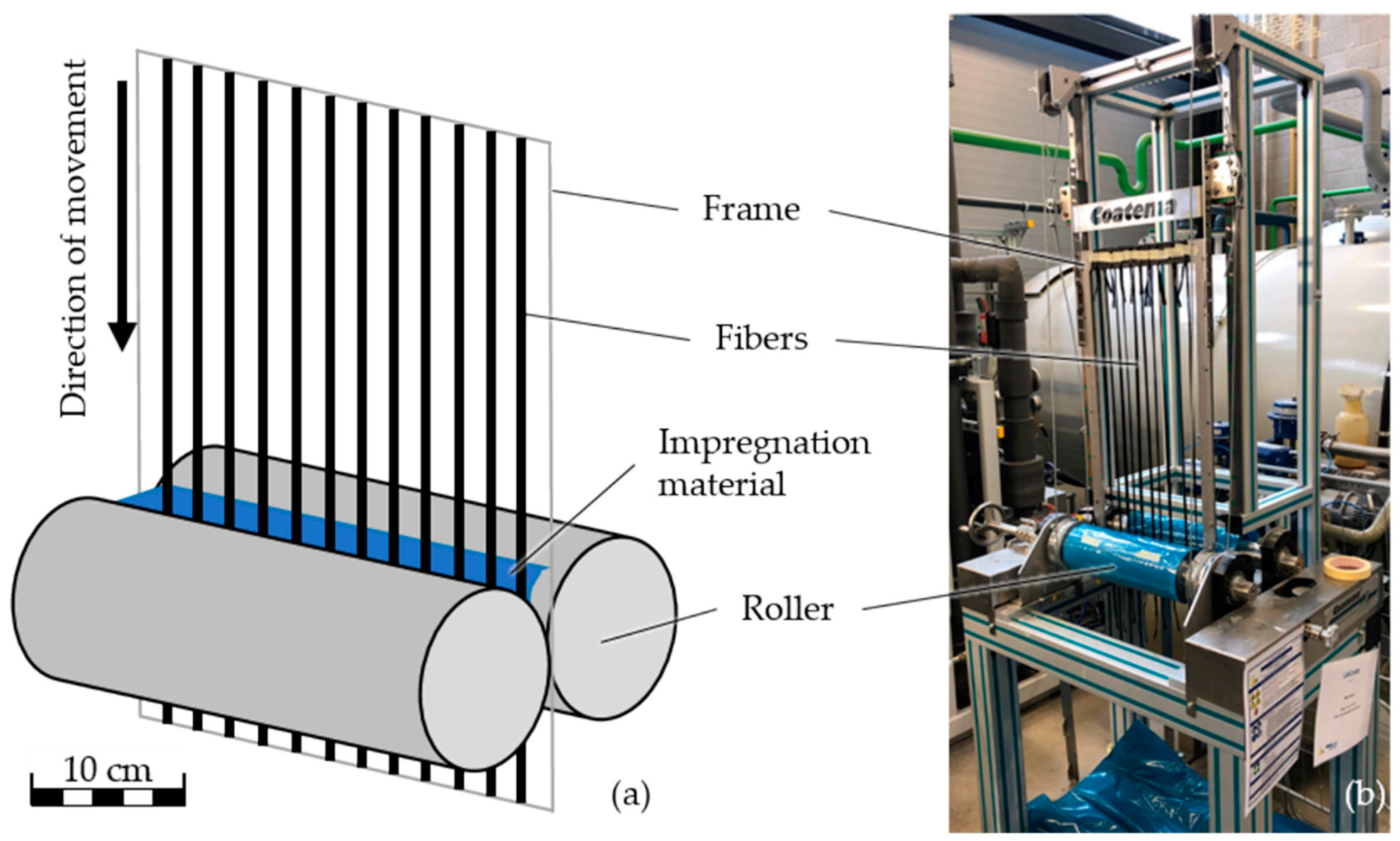
2.2. Methods
3. Results and Discussion
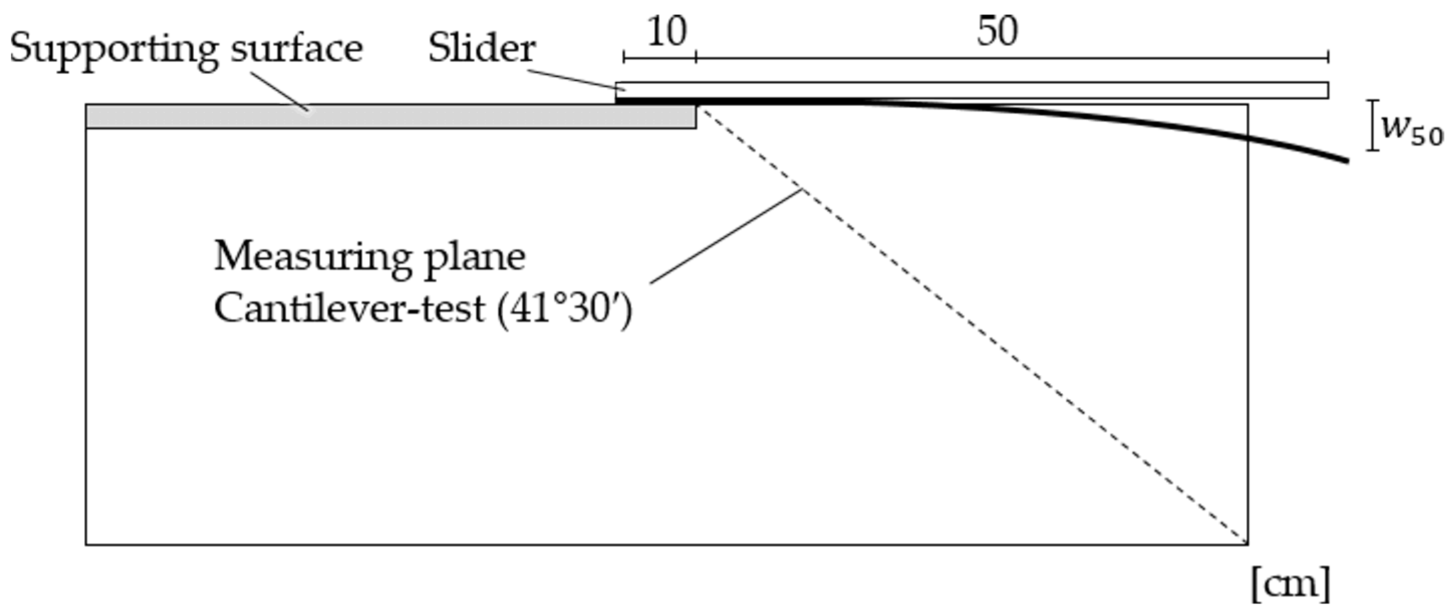
3.1. Cantilever Tests
3.2. Rolling Ball Tests
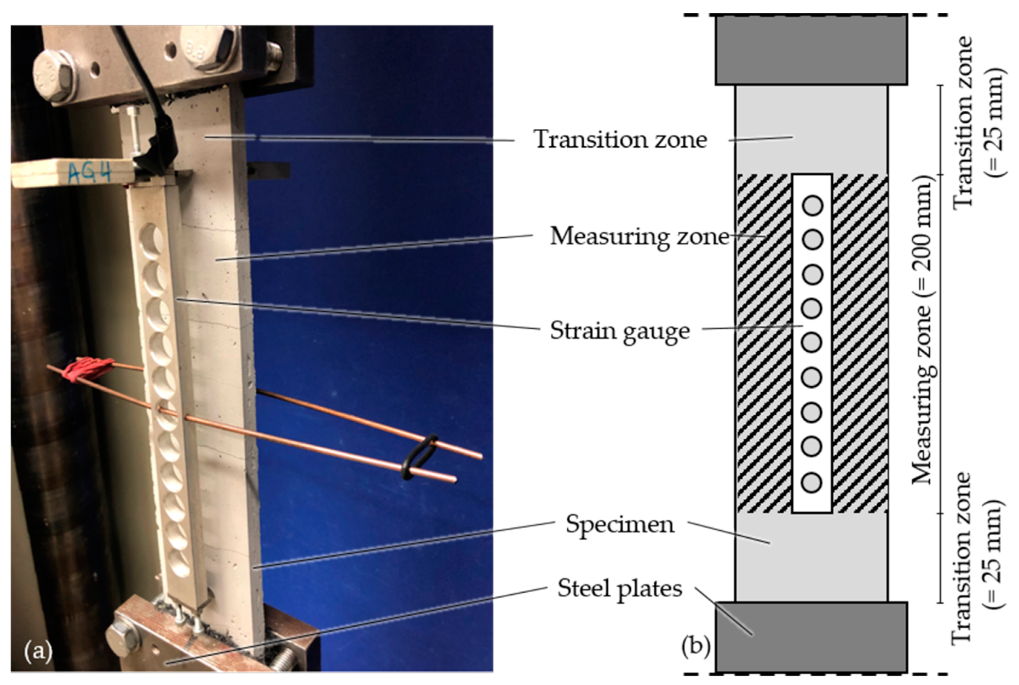
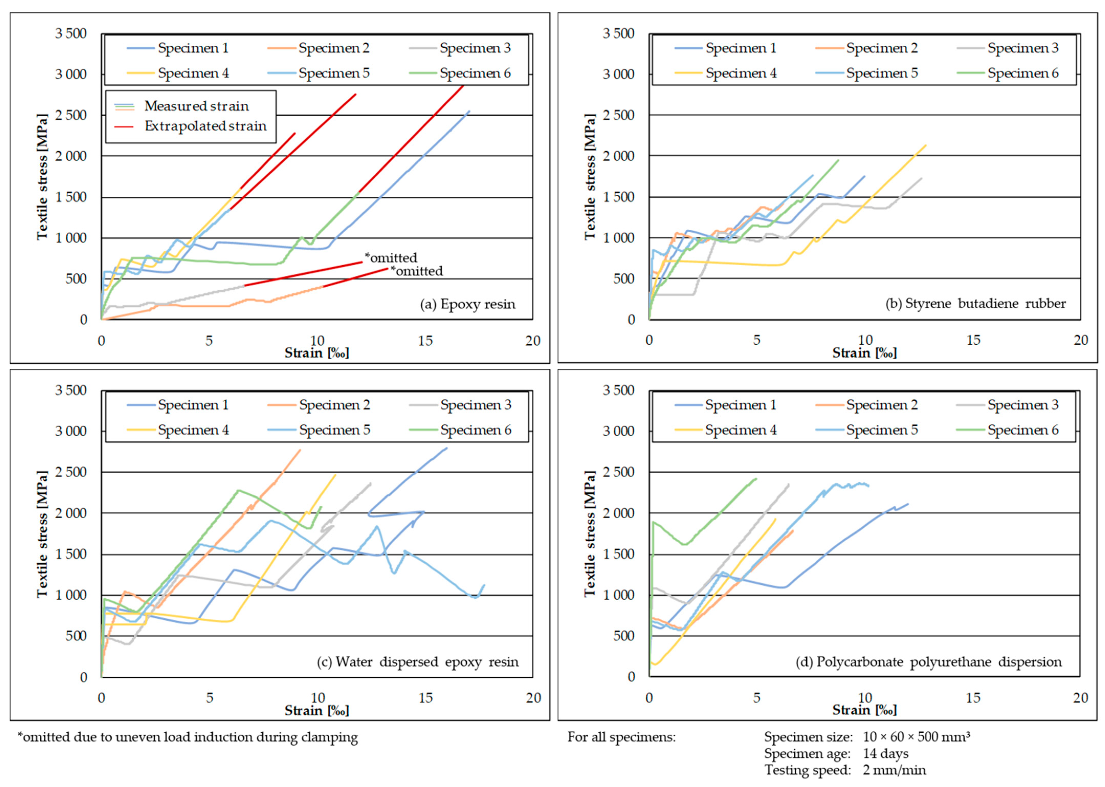
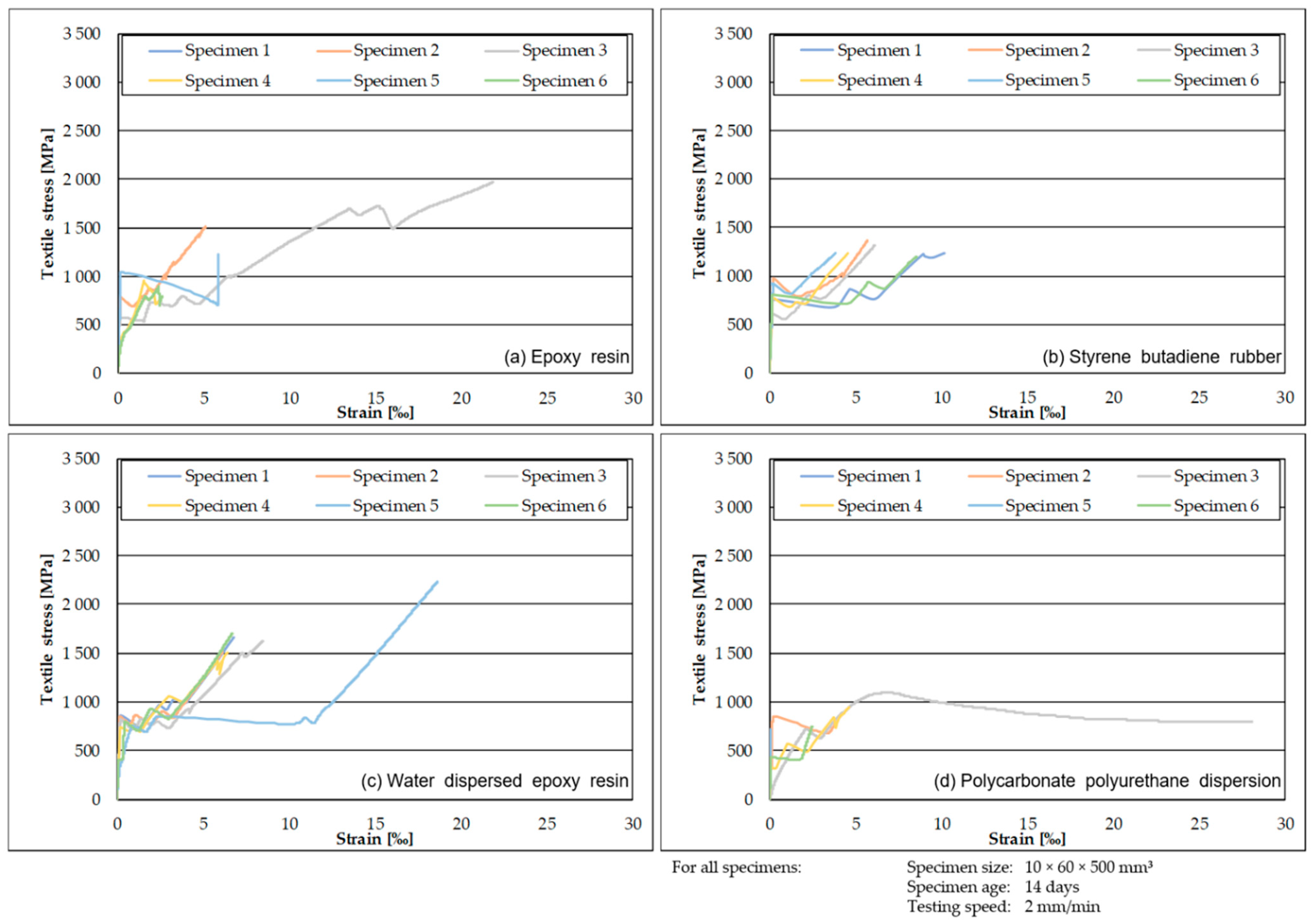
3.3. Tensile Tests
4. Conclusions
- A modified cantilever test based on modeling textiles as a cantilever fixed on one side and measuring the deflection is suitable to compare the bending stiffness of stiff, impregnated textiles.
- A rolling ball test enables the determination of the progress of the curing reaction of impregnation materials, allowing an assessment of the timeframe in which textiles must be placed within the concrete to ensure curing within the concrete matrix.
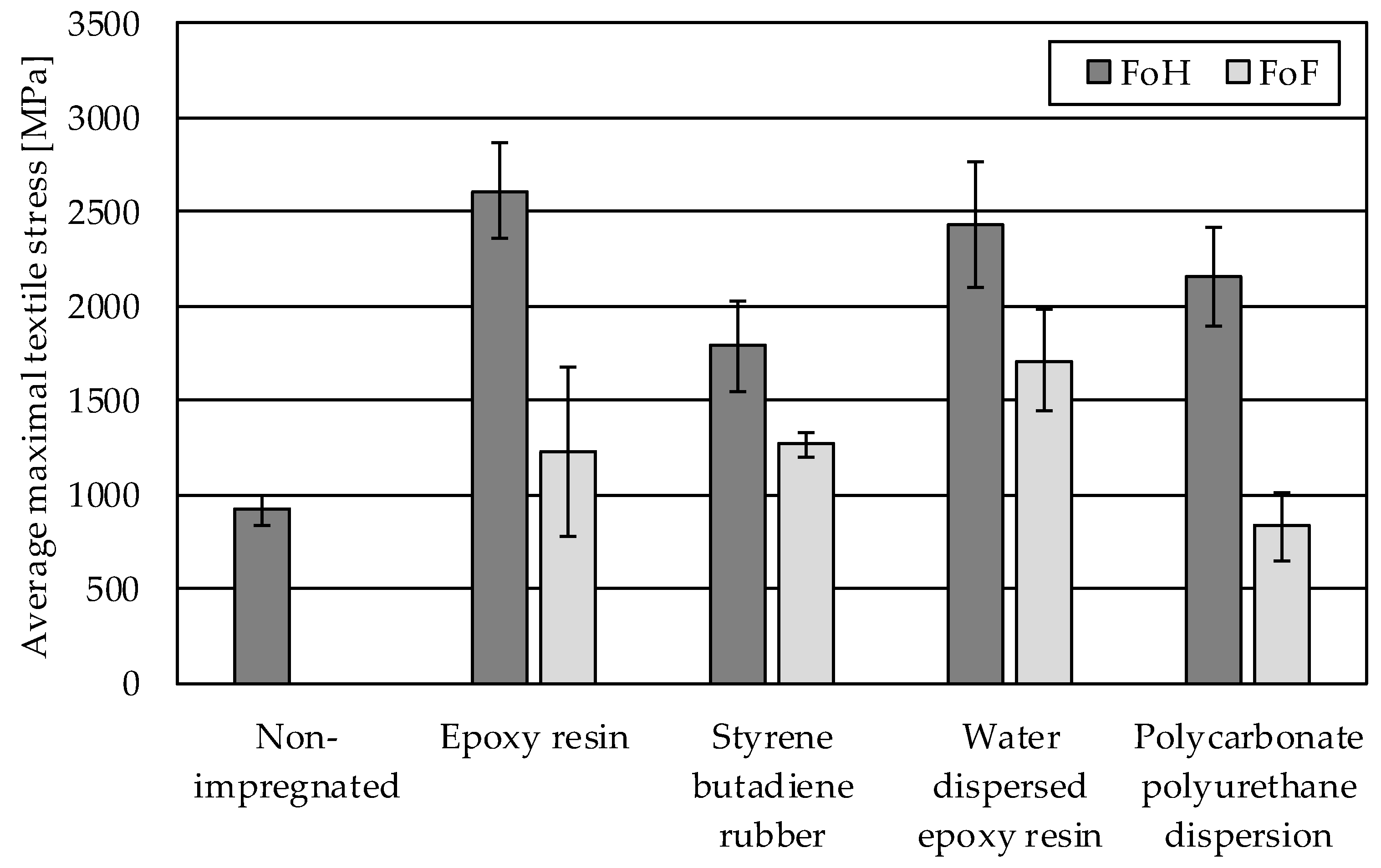
- Impregnated and cured textile reinforcements significantly improve the tensile strength of reinforced concrete specimens compared to non-impregnated reinforcement. This effect is confirmed for materials reported in the literature (epoxy resin, increase in strength of 185%; styrene butadiene rubber, increase in strength of 95%) as well as novel materials analyzed in this study (water-dispersed epoxy resin, increase in strength of 165%; polycarbonate polyurethane dispersion, increase in strength of 135%).
- For impregnated textiles cured within the concrete, mechanical performance is lower compared to the respective textiles cured prior to insertion into concrete. However, for all materials except polycarbonate polyurethane dispersion, performance is higher than the non-impregnated control (epoxy resin, increase in strength of 34%; styrene butadiene rubber, increase in strength of 38%; water-dispersed epoxy resin, increase in strength of 87%; polycarbonate polyurethane dispersion, loss in strength of 9%).
- Since water-dispersed epoxy resin cured within concrete showed the highest performance of all materials with a significant formation of cracks and high bonding properties cured within concrete (1711 MPa) and achieved similar performance to styrene butadiene rubber cured prior to insertion into concrete (1791 MPa), which is currently used in the industry, this material class warrants further investigation for the integration in additive manufacturing processes like 3D printing and extrusion.
Author Contributions
Funding
Institutional Review Board Statement
Informed Consent Statement
Data Availability Statement
Conflicts of Interest
Appendix A

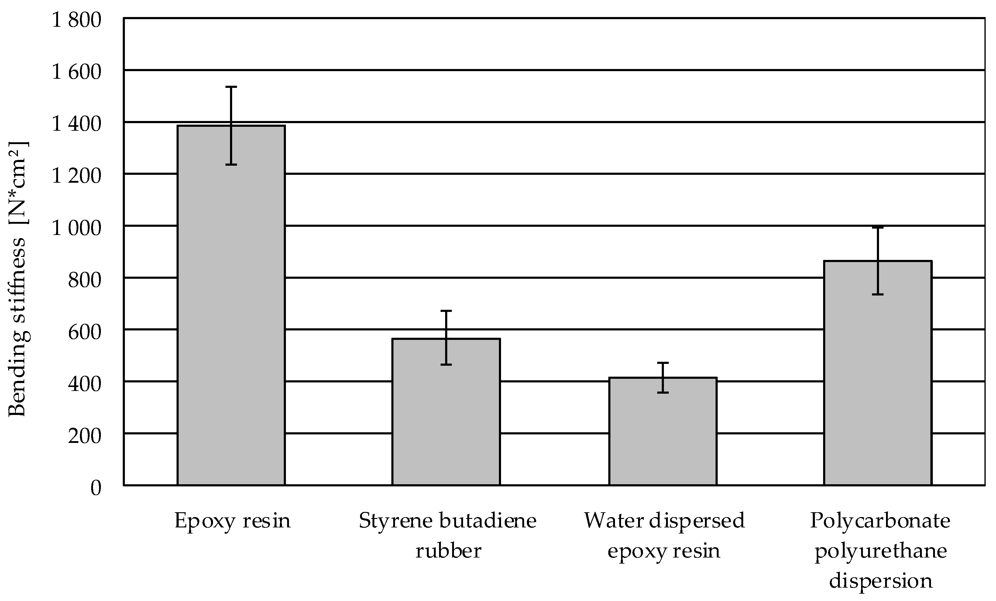
| Material | Specimen No. | M | b | lo | w50 | EI | Average EI | Standard Deviation EI |
|---|---|---|---|---|---|---|---|---|
| Epoxy resin | 1 | 1360.0 | 0.50 | 50 | 1.8 | 1544.2 | 1388.9 | 149.6 |
| 2 | 1163.6 | 0.55 | 50 | 1.9 | 1376.8 | |||
| 3 | 1163.6 | 0.55 | 50 | 2.1 | 1245.7 | |||
| Styrene butadiene rubber | 1 | 1680.0 | 0.25 | 50 | 2.5 | 686.7 | 566.6 | 104.6 |
| 2 | 1266.7 | 0.30 | 50 | 3.0 | 517.8 | |||
| 3 | 1142.9 | 0.35 | 50 | 3.3 | 495.5 | |||
| Water-dispersed epoxy resin | 1 | 1700.0 | 0.20 | 50 | 3.1 | 448.3 | 414.1 | 55.3 |
| 2 | 1520.0 | 0.25 | 50 | 3.5 | 443.8 | |||
| 3 | 1200.0 | 0.35 | 50 | 4.9 | 350.4 | |||
| Polycarbonate polyurethane dispersion | 1 | 1920.0 | 0.25 | 50 | 2.1 | 934.3 | 865.4 | 130.1 |
| 2 | 2200.0 | 0.20 | 50 | 1.9 | 946.6 | |||
| 3 | 1400.0 | 0.30 | 50 | 2.4 | 715.3 |
References
- European Commission. On Resource Efficiency Opportunities in the Building Sector. COM(2014) 445 Final, Brussels, 2014. Available online: https://ec.europa.eu/environment/eussd/pdf/SustainableBuildingsCommunication.pdf (accessed on 13 October 2022).
- European Commission. Communication From the Commission to the European Parliament, the Council, the European Economic and Social Committee and the Committee of the Regions: Roadmap to a Resource Efficient Europe. COM(2011) 571 Final, Brussels, 2011. Available online: https://eur-lex.europa.eu/legal-content/EN/TXT/PDF/?uri=CELEX:52011DC0571&from=EN (accessed on 13 October 2022).
- Ruuska, A.; Häkkinen, T. Material Efficiency of Building Construction. Buildings 2014, 4, 266–294. [Google Scholar] [CrossRef] [Green Version]
- Beyond Zero Emissions. Rethinking Cement: Zero Carbon Industry Plan; Beyond Zero Emissions Inc.: Fitzroy, Australia, 2017; ISBN 978-0-9923580-2-0. [Google Scholar]
- Farzampour Alireza. Temperature and humidity effects on behavior of grouts. Adv. Concr. Constr. 2017, 5, 659–669. [Google Scholar] [CrossRef]
- Mansouri, I.; Shahheidari, F.S.; Hashemi, S.M.A.; Farzampour, A. Investigation of steel fiber effects on concrete abrasion resistance. Adv. Concr. Constr. 2020, 9, 367–374. [Google Scholar] [CrossRef]
- Chalangaran, N.; Farzampour, A.; Paslar, N.; Fatemi, H. Experimental investigation of sound transmission loss in concrete containing recycled rubber crumbs. Adv. Concr. Constr. 2021, 11, 447–454. [Google Scholar] [CrossRef]
- Adesina, A. Recent advances in the concrete industry to reduce its carbon dioxide emissions. Environ. Chall. 2020, 1, 100004. [Google Scholar] [CrossRef]
- Bostanci, S.C.; Limbachiya, M.; Kew, H. Use of recycled aggregates for low carbon and cost effective concrete construction. J. Clean. Prod. 2018, 189, 176–196. [Google Scholar] [CrossRef] [Green Version]
- Chalangaran, N.; Farzampour, A.; Paslar, N. Nano Silica and Metakaolin Effects on the Behavior of Concrete Containing Rubber Crumbs. CivilEng 2020, 1, 264–274. [Google Scholar] [CrossRef]
- Watari, T.; Cao, Z.; Hata, S.; Nansai, K. Efficient use of cement and concrete to reduce reliance on supply-side technologies for net-zero emissions. Nat. Commun. 2022, 13, 4158. [Google Scholar] [CrossRef]
- Farzampour, A. Compressive Behavior of Concrete under Environmental Effects. In Compressive Strength of Concrete; Kryvenko, P., Ed.; IntechOpen: London, UK, 2020; ISBN 978-1-78985-567-8. [Google Scholar]
- Peled, A.; Bentur, A.; Mobasher, B. Textile Reinforced Concrete; CRC Press: London, UK, 2017; ISBN 9781315119151. [Google Scholar]
- Hegger, J.; Voss, S. Investigations on the bearing behaviour and application potential of textile reinforced concrete. Eng. Struct. 2008, 30, 2050–2056. [Google Scholar] [CrossRef]
- Koutas, L.N.; Tetta, Z.; Bournas, D.A.; Triantafillou, T.C. Strengthening of Concrete Structures with Textile Reinforced Mortars: State-of-the-Art Review. J. Compos. Constr. 2019, 23, 3118001. [Google Scholar] [CrossRef]
- Friese, D.; Scheurer, M.; Hahn, L.; Gries, T.; Cherif, C. Textile reinforcement structures for concrete construction applications––a review. J. Compos. Mater. 2022, 56, 002199832211271. [Google Scholar] [CrossRef]
- Laiblová, L.; Pešta, J.; Kumar, A.; Hájek, P.; Fiala, C.; Vlach, T.; Kočí, V. Environmental Impact of Textile Reinforced Concrete Facades Compared to Conventional Solutions-LCA Case Study. Materials 2019, 12, 3194. [Google Scholar] [CrossRef] [Green Version]
- Scope, C.; Guenther, E.; Schütz, J.; Mielecke, T.; Mündecke, E.; Schultze, K.; Saling, P. Aiming for life cycle sustainability assessment of cement-based composites: A trend study for wall systems of carbon concrete: Dresden Nexus Conference 2020-Session 4-Circular economy for building with secondary construction materials to minimise resource use and land use. Civ. Eng. Des. 2020, 2, 143–158. [Google Scholar] [CrossRef]
- Stoiber, N.; Hammerl, M.; Kromoser, B. Cradle-to-gate life cycle assessment of CFRP reinforcement for concrete structures: Calculation basis and exemplary application. J. Clean Prod. 2021, 280, 124300. [Google Scholar] [CrossRef]
- Curbach, M.; Jesse, F. Eigenschaften und Anwendung von Textilbeton. Beton-Und Stahlbetonbau 2009, 104, 9–16. [Google Scholar] [CrossRef]
- Textile Fibre Composites in Civil Engineering; Triantafillou, T. (Ed.) Elsevier: Amsterdam, The Netherlands, 2016; ISBN 9781782424468. [Google Scholar]
- Mechtcherine, V.; Michel, A.; Liebscher, M.; Schneider, K.; Großmann, C. Mineral-impregnated carbon fiber composites as novel reinforcement for concrete construction: Material and automation perspectives. Autom. Constr. 2020, 110, 103002. [Google Scholar] [CrossRef]
- Nadiv, R.; Peled, A.; Mechtcherine, V.; Hempel, S.; Schroefl, C. Micro- and nanoparticle mineral coating for enhanced properties of carbon multifilament yarn cement-based composites. Compos. Part B Eng. 2017, 111, 179–189. [Google Scholar] [CrossRef]
- Schneider, K.; Lieboldt, M.; Liebscher, M.; Fröhlich, M.; Hempel, S.; Butler, M.; Schröfl, C.; Mechtcherine, V. Mineral-Based Coating of Plasma-Treated Carbon Fibre Rovings for Carbon Concrete Composites with Enhanced Mechanical Performance. Materials 2017, 10, 360. [Google Scholar] [CrossRef]
- Raoof, S.M.; Koutas, L.N.; Bournas, D.A. Bond between textile-reinforced mortar (TRM) and concrete substrates: Experimental investigation. Compos. Part B Eng. 2016, 98, 350–361. [Google Scholar] [CrossRef]
- Glowania, M.; Gries, T.; Schoene, J.; Schleser, M.; Reisgen, U. Innovative Coating Technology for Textile Reinforcements of Concrete Applications. KEM 2011, 466, 167–173. [Google Scholar] [CrossRef]
- Beckmann, B.; Bielak, J.; Bosbach, S.; Scheerer, S.; Schmidt, C.; Hegger, J.; Curbach, M. Collaborative research on carbon reinforced concrete structures in the CRC/TRR 280 project. Civ. Eng. Des. 2021, 3, 99–109. [Google Scholar] [CrossRef]
- Mechtcherine, V.; Michel, A.; Liebscher, M.; Schmeier, T. Extrusion-Based Additive Manufacturing with Carbon Reinforced Concrete: Concept and Feasibility Study. Materials 2020, 13, 2568. [Google Scholar] [CrossRef] [PubMed]
- Bos, F.P.; Lucas, S.S.; Wolfs, R.J.; Salet, T.A. (Eds.) Second RILEM International Conference on Concrete and Digital Fabrication; Springer International Publishing: Cham, Switzerland, 2020; ISBN 978-3-030-49915-0. [Google Scholar]
- Kalthoff, M.; Raupach, M.; Matschei, T. Investigation into the Integration of Impregnated Glass and Carbon Textiles in a Laboratory Mortar Extruder (LabMorTex). Materials 2021, 14, 7406. [Google Scholar] [CrossRef] [PubMed]
- Kalthoff, M.; Raupach, M.; Matschei, T. Extrusion and Subsequent Transformation of Textile-Reinforced Mortar Components—Requirements on the Textile, Mortar and Process Parameters with a Laboratory Mortar Extruder (LabMorTex). Buildings 2022, 12, 726. [Google Scholar] [CrossRef]
- Teijin Carbon Europe GmbH. Tenax Filament Yarn Product Data Sheet. Available online: https://www.teijincarbon.com/fileadmin/PDF/Datenbl%C3%A4tter_dt/Product_Data_Sheet_TSG01de__EU_Filament___DE_.pdf (accessed on 13 October 2022).
- DIN 53362:2003-10; Testing of Plastics Films and Textile Fabrics (Excluding Nonwovens), Coated or not Coated Fabrics–Determination of Stiffness in Bending–Method According to Cantilever. Beuth Verlag GmbH: Berlin, Germany, 2003. [CrossRef]
- Duncan, B.C.; Lay, L. An Intercomparison of Tack Measurements. NPL Report, Teddington. 1999. Available online: http://eprintspublications.npl.co.uk/1246/ (accessed on 1 December 2022).
- D10 Committee. Test Method for Tack of Pressure-Sensitive Adhesives by Rolling Ball; ASTM International: West Conshohocken, PA, USA, 2007. [Google Scholar] [CrossRef]
- Recommendation of RILEM TC 232-TDT: Test methods and design of textile reinforced concrete. Mater. Struct. 2016, 49, 4923–4927. [CrossRef] [Green Version]
- Bielak, J. Shear in Slabs with Non-Metallic. Reinforcement. Dissertation, RWTH Aachen University, Aachen, Germany, 2021. [Google Scholar] [CrossRef]
- Morales Cruz, C. Crack-Distributing Carbon Textile Reinforced Concrete Protection Layers. Dissertation, RWTH Aachen University, Aachen, Germany, 2020. [Google Scholar] [CrossRef]
- Kulas, C. Load-Bearing Behavior of Impregnated Textile Reinforcements for Concrete Members. Dissertation, RWTH Aachen University, Aachen, Germany, 2014. [Google Scholar]
- Carozzi, F.G.; Poggi, C. Mechanical properties and debonding strength of Fabric Reinforced Cementitious Matrix (FRCM) systems for masonry strengthening. Compos. Part B Eng. 2015, 70, 215–230. [Google Scholar] [CrossRef]
- Dilthey, U.; Schleser, M.; Puterman, M. Investigation and improvement of concrete reinforced with epoxy impregnated fabrics. In Proceedings of the 12th International Congress ’Polymers in Concrete’, ICPIC 07, Chuncheon, Korea, 26–28 September 2007; Yeon, K.-S., Ed.; Kangwoon National University: Chancheon, Republic of Korea, 2007. [Google Scholar]


| Titer [tex] | Tensile Strength [MPa] | Young’s Modulus [GPa] | Elongation at Break [%] | Filament Diameter [μm] | Sizing Content [%] |
|---|---|---|---|---|---|
| 1600 | 4300 | 250 | 1.7 | 7.0 | 1.3 |
| Ingredient | Amount [kg/m3] |
|---|---|
| CEM I 42.5 R | 620 |
| Fly ash | 113.6 |
| Sand 0.1–0.5 mm | 552.3 |
| Quartz powder 0–0.250 | 530 |
| Silica fume powder | 36 |
| Water | 319.3 |
| PCE super-plasticizer | 2.5 |
| Resin | Curing Agent | Designation in This Work | Dynamic Viscosity [mPa*s] | Density at 23 °C [g/cm3] |
|---|---|---|---|---|
| Bisphenol A/F resin | Polyetherdiamine | Epoxy resin | 200–400 | 1.15 |
| Watery dispersion of carboxylated styrene-butadiene-copolymers | Etherified methylolmelamine-solution | Styrene-butadiene-rubber dispersion | 1000 | 1.02 |
| Water-dispersed epoxy resin | Amine polymer | dispeler-dispersed epoxy resin | 250 | 1.05 |
| Anionic polycarbonate polyurethane dispersion | Hydrophilic, aliphatic polyisocyanate based on hexamethylene-diisocyanate | Polycarbonate polyurethane dispersion | 1400 1 | 1.05 |
| Impregnation Material | Specimen Number | Deflection [cm] | Average Deflection [cm] |
|---|---|---|---|
| Epoxy resin | 1 | 1.8 | 1.93 |
| 2 | 1.9 | ||
| 3 | 2.1 | ||
| Styrene-butadiene-rubber dispersion | 1 | 2.5 | 2.93 |
| 2 | 3.0 | ||
| 3 | 3.3 | ||
| Water-dispersed epoxy resin | 1 | 3.1 | 3.83 |
| 2 | 3.5 | ||
| 3 | 4.9 | ||
| Polycarbonate polyurethane dispersion | 1 | 2.1 | 2.13 |
| 2 | 1.9 | ||
| 3 | 2.4 |
| Impregnation Material | Type of Curing | Average Number of Cracks | Average Maximum Tensile Stress [MPa] | Standard Deviation of Maximum Tensile Stress [MPa] |
|---|---|---|---|---|
| Epoxy resin | Cured in air (FoH) | 4.2 | 2610 | 256 |
| Cured in concrete (FoF) | 4.2 | 1228 | 445 | |
| Styrene-butadiene-rubber dispersion | Cured in air (FoH) | 5.2 | 1791 | 238 |
| Cured in concrete (FoF) | 3.5 | 1264 | 64 | |
| Water-dispersed epoxy resin | Cured in air (FoH) | 4.2 | 2430 | 333 |
| Cured in concrete (FoF) | 4.7 | 1711 | 268 | |
| Polycarbonate polyurethane dispersion | Cured in air (FoH) | 3.2 | 2159 | 260 |
| Cured in concrete (FoF) | 2.2 | 830 | 180 |
Publisher’s Note: MDPI stays neutral with regard to jurisdictional claims in published maps and institutional affiliations. |
© 2022 by the authors. Licensee MDPI, Basel, Switzerland. This article is an open access article distributed under the terms and conditions of the Creative Commons Attribution (CC BY) license (https://creativecommons.org/licenses/by/4.0/).
Share and Cite
Scheurer, M.; Kalthoff, M.; Matschei, T.; Raupach, M.; Gries, T. Analysis of Curing and Mechanical Performance of Pre-Impregnated Carbon Fibers Cured within Concrete. Textiles 2022, 2, 657-672. https://doi.org/10.3390/textiles2040038
Scheurer M, Kalthoff M, Matschei T, Raupach M, Gries T. Analysis of Curing and Mechanical Performance of Pre-Impregnated Carbon Fibers Cured within Concrete. Textiles. 2022; 2(4):657-672. https://doi.org/10.3390/textiles2040038
Chicago/Turabian StyleScheurer, Martin, Matthias Kalthoff, Thomas Matschei, Michael Raupach, and Thomas Gries. 2022. "Analysis of Curing and Mechanical Performance of Pre-Impregnated Carbon Fibers Cured within Concrete" Textiles 2, no. 4: 657-672. https://doi.org/10.3390/textiles2040038