
Non-Conventional Hybrid Microporous Layers for Enhanced Performance and Durability of PEM Fuel Cells

 , ,
, ,  , and
, and 
Abstract
:1. Introduction
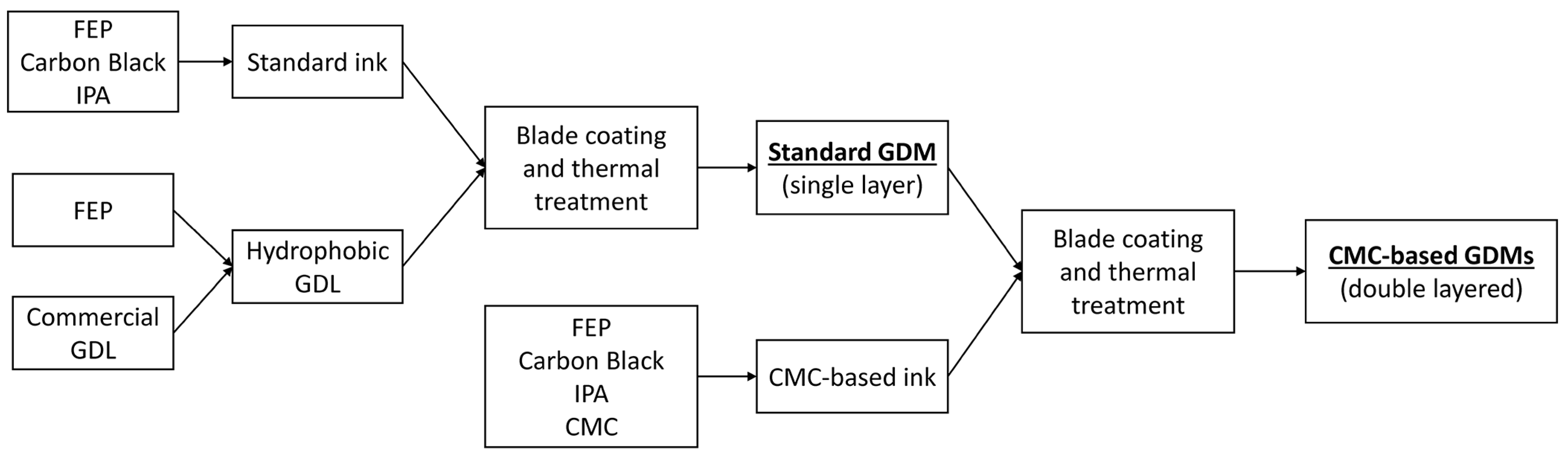
2. Materials and Methods
3. Results
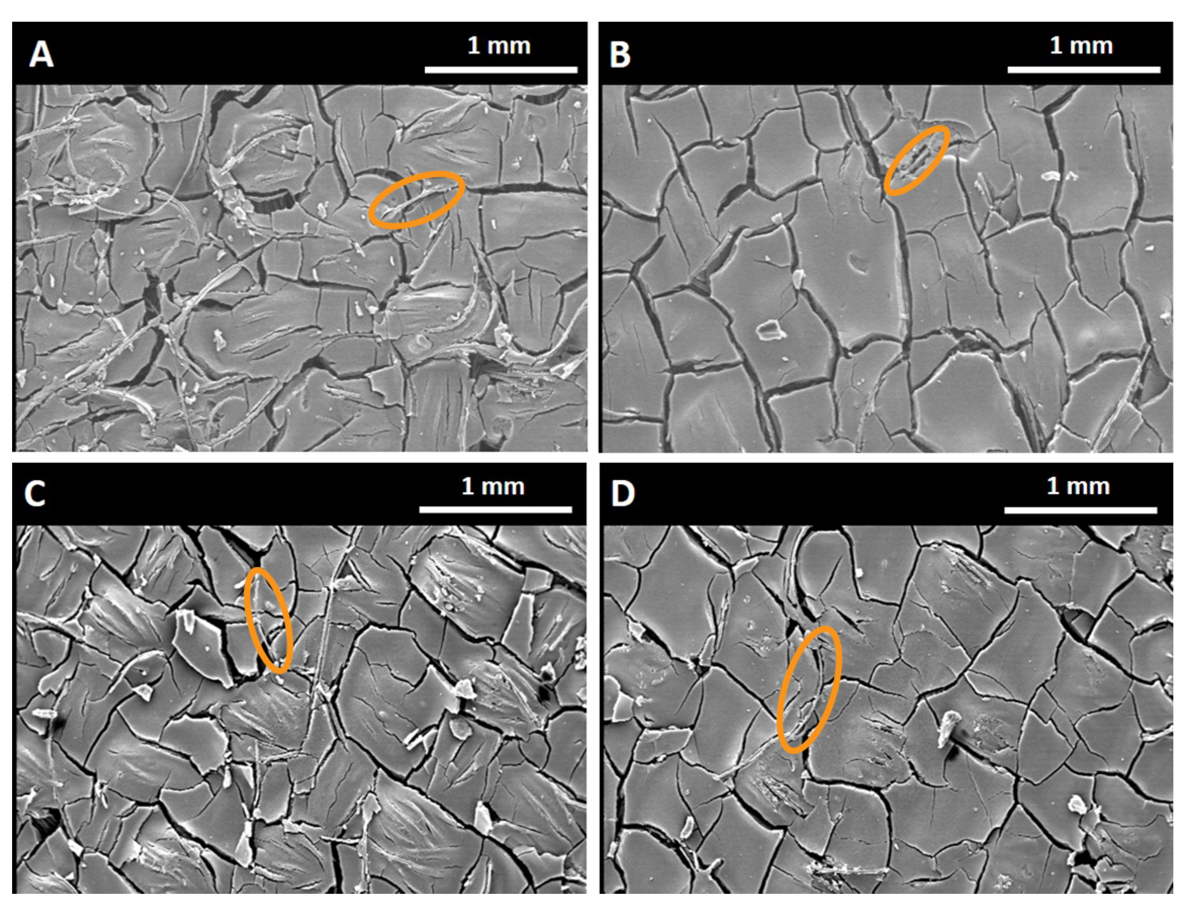
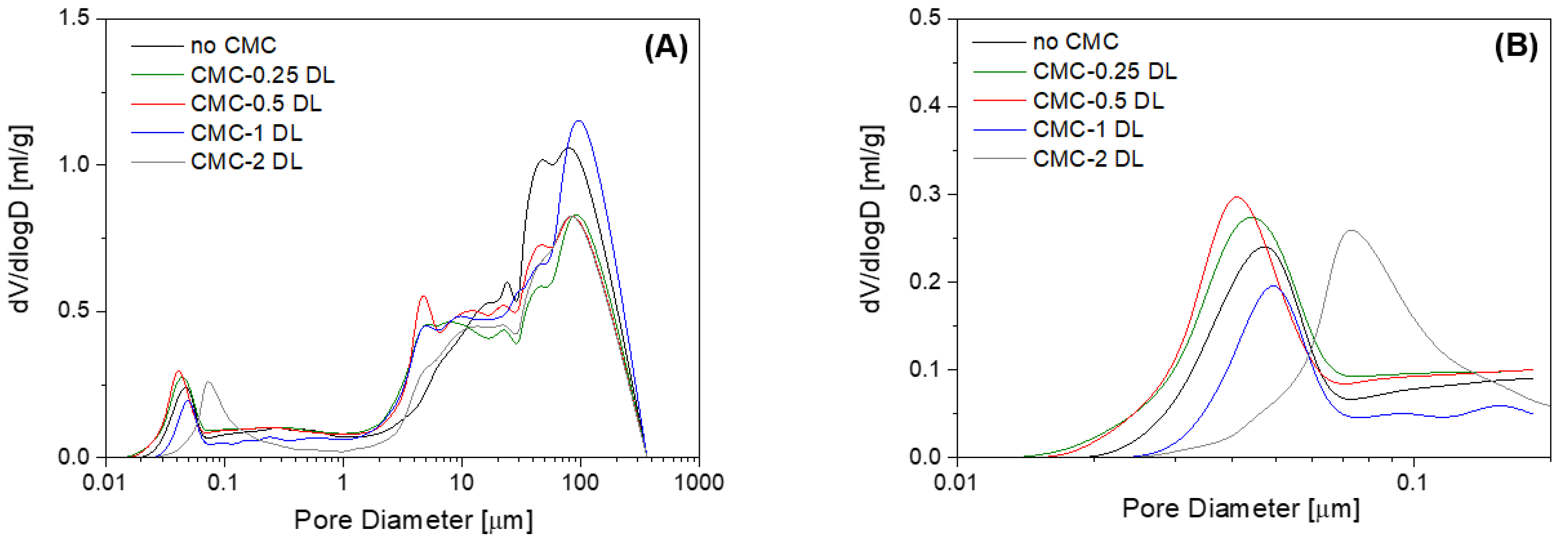
3.1. Morphology
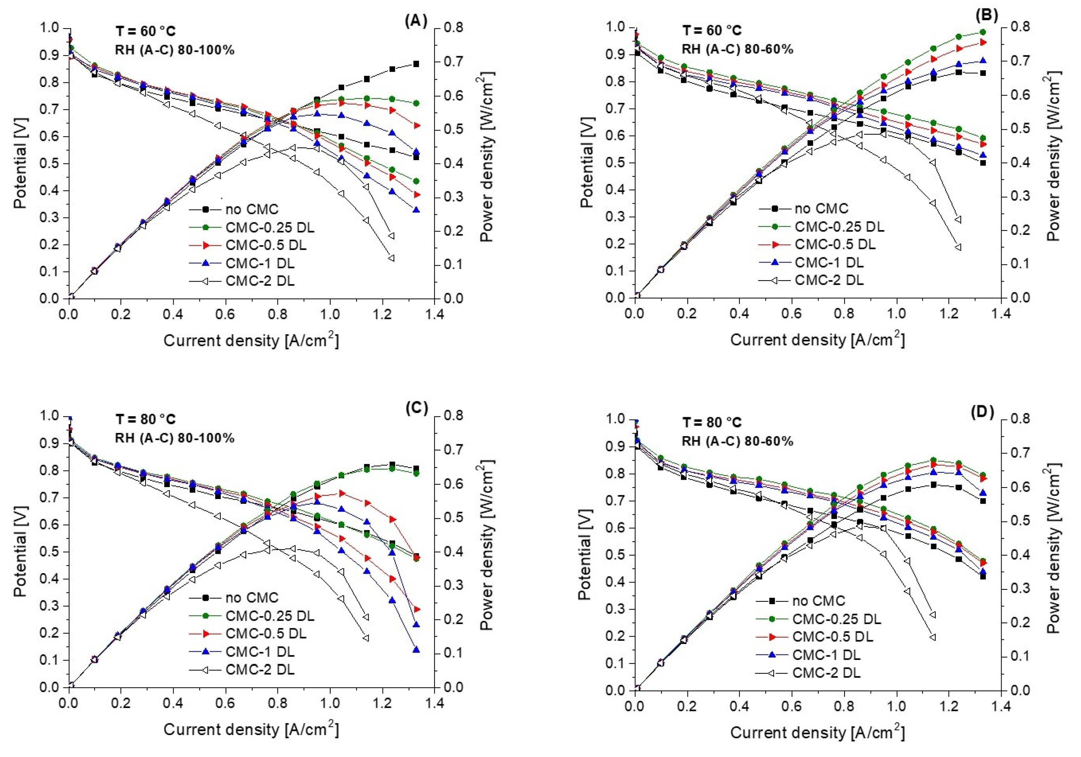
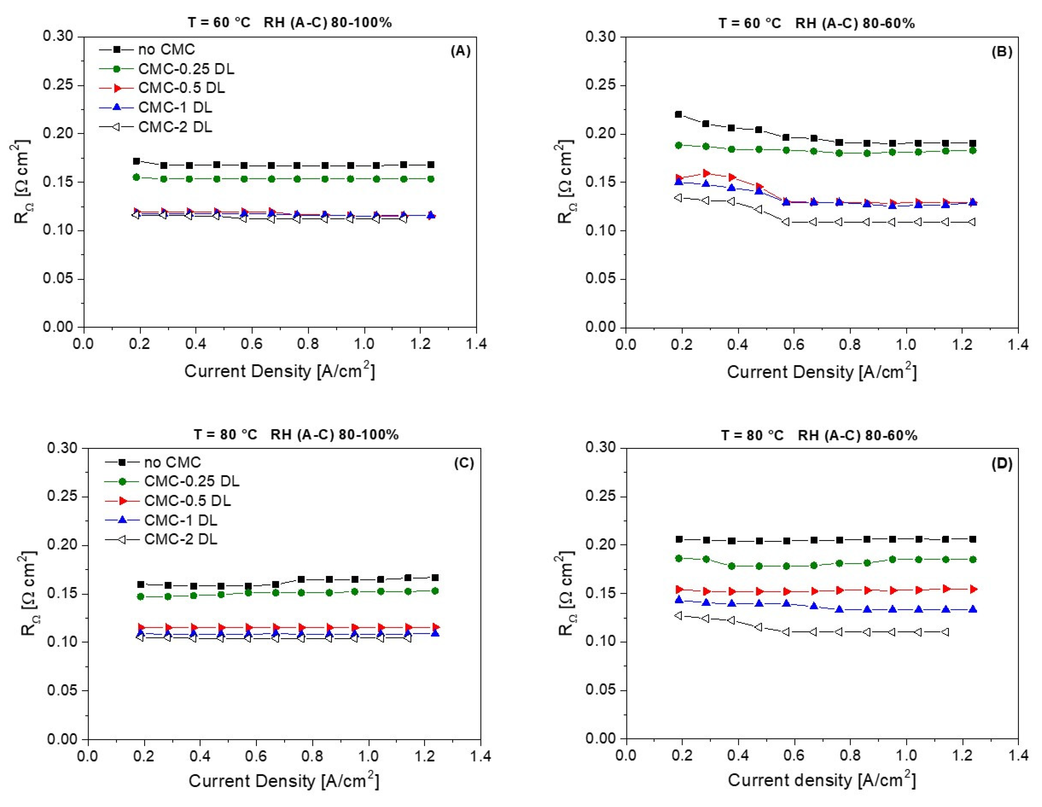
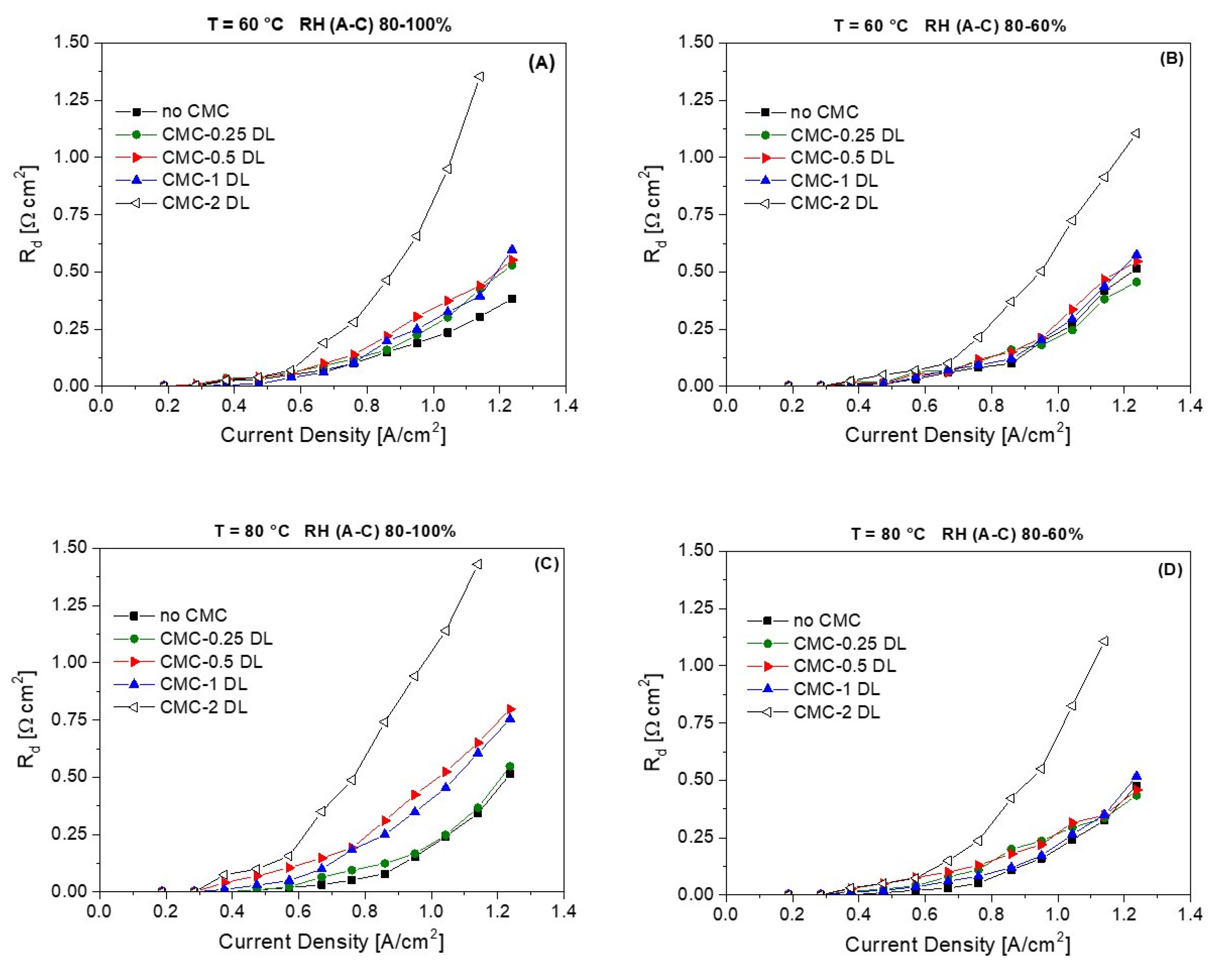
3.2. Electrochemical Characterization
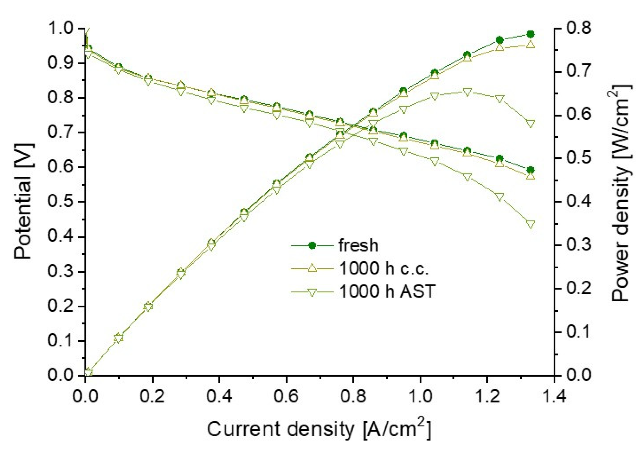
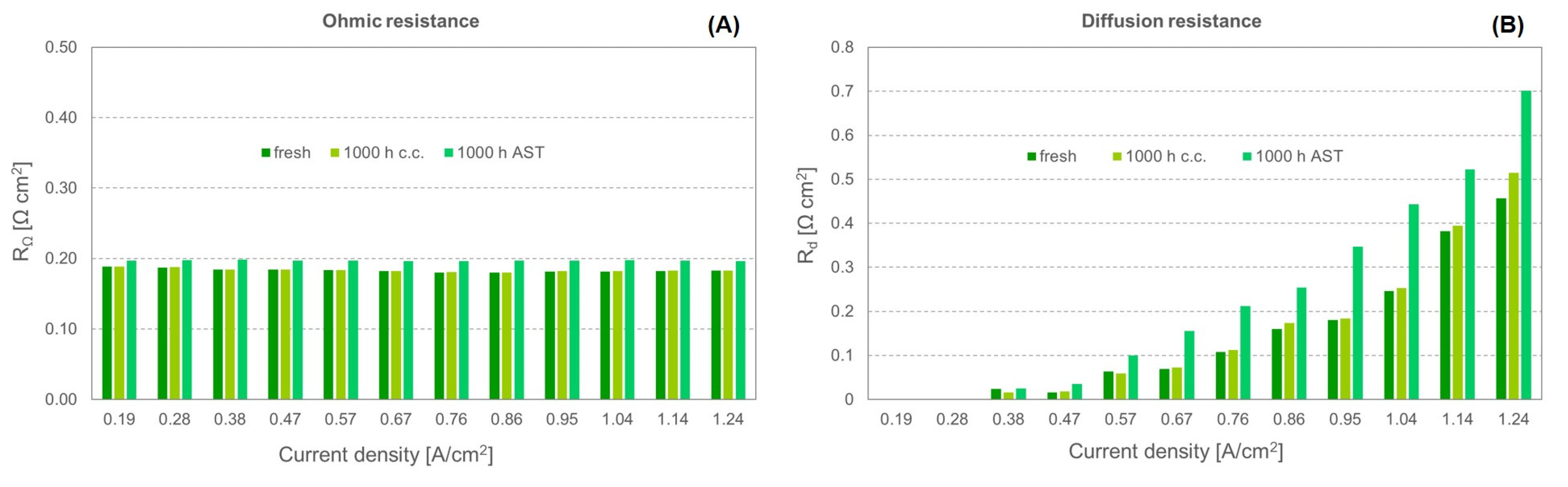
3.3. Durability
4. Conclusions
Supplementary Materials
Author Contributions
Funding
Data Availability Statement
Conflicts of Interest
References
- Sun, C.; Negro, E.; Vezzù, K.; Pagot, G.; Cavinato, G.; Nale, A.; Herve, Y.; Di, V. Hybrid inorganic-organic proton-conducting membranes based on SPEEK doped with WO3 nanoparticles for application in vanadium redox flow batteries. Electrochim. Acta 2019, 309, 311–325. [Google Scholar] [CrossRef]
- Barbir, F. PEM Fuel Cells: Theory and Practice; Academic Press: Cambridge, MA, USA, 2013; ISBN 9780123877109. [Google Scholar]
- Park, S.; Lee, J.-W.; Popov, B.N. A review of gas diffusion layer in PEM fuel cells: Materials and designs. Int. J. Hydrog. Energy 2012, 37, 5850–5865. [Google Scholar] [CrossRef]
- Popov, B.N.; Park, S.; Lee, J.W. Effect of Gas Diffusion Layer Structure on the Performance of Polymer Electrolyte Membrane Fuel Cell. In Electrocatalysts for Low Temperature Fuel Cells: Fundamentals and Recent Trends; Wiley: Hoboken, NJ, USA, 2017; p. 616. ISBN 9783527803873. [Google Scholar]
- Ijaodola, O.S.; El- Hassan, Z.; Ogungbemi, E.; Khatib, F.N.; Wilberforce, T.; Thompson, J.; Olabi, A.G. Energy efficiency improvements by investigating the water flooding management on proton exchange membrane fuel cell (PEMFC). Energy 2019, 179, 246–267. [Google Scholar] [CrossRef]
- Majlan, E.H.; Rohendi, D.; Daud, W.R.W.; Husaini, T.; Haque, M.A. Electrode for proton exchange membrane fuel cells: A review. Renew. Sustain. Energy Rev. 2018, 89, 117–134. [Google Scholar] [CrossRef]
- Cindrella, L.; Kannan, A.M.; Lin, J.F.; Saminathan, K.; Ho, Y.; Lin, C.W.; Wertz, J. Gas diffusion layer for proton exchange membrane fuel cells-A review. J. Power Sources 2009, 194, 146–160. [Google Scholar] [CrossRef]
- Chen, J.; Matsuura, T.; Hori, M. Novel gas diffusion layer with water management function for PEMFC. J. Power Sources 2004, 131, 155–161. [Google Scholar] [CrossRef]
- Peng, M.; Dong, E.; Chen, L.; Wang, Y.; Tao, W.-Q. Effects of Cathode Gas Diffusion Layer Configuration on the Performance of Open Cathode Air-Cooled Polymer Electrolyte. Energies 2022, 15, 6262. [Google Scholar] [CrossRef]
- Kitahara, T.; Konomi, T.; Nakajima, H. Microporous layer coated gas diffusion layers for enhanced performance of polymer electrolyte fuel cells. J. Power Sources 2010, 95, 2202–2211. [Google Scholar] [CrossRef]
- Kim, T.; Lee, S.; Park, H. A study of water transport as a function of the micro-porous layer arrangement in PEMFCs. Int. J. Hydrog. Energy 2010, 35, 8631–8643. [Google Scholar] [CrossRef]
- Wu, R.; Liao, Q.; Zhu, X.; Wang, H. Liquid and oxygen transport through bilayer gas diffusion materials of proton exchange membrane fuel cells. Int. J. Heat Mass Transf. 2012, 55, 6363–6373. [Google Scholar] [CrossRef]
- Chun, J.H.; Jo, D.H.; Kim, S.G.; Park, S.H.; Lee, C.H.; Kim, S.H. Improvement of the mechanical durability of micro porous layer in a proton exchange membrane fuel cell by elimination of surface cracks. Renew. Energy 2012, 48, 35–41. [Google Scholar] [CrossRef]
- Martín-Alcántara, A.; González-Morán, L.; Pino, J.; Guerra, J. Effect of the Gas Diffusion Layer Design on the Water Management and Cell Performance of a PEM Fuel Cell. Processes 2022, 10, 1395. [Google Scholar] [CrossRef]
- Sim, J.; Kang, M.; Min, K. Effects of basic gas diffusion layer components on PEMFC performance with capillary pressure gradient. Int. J. Hydrog. Energy 2021, 46, 27731–27748. [Google Scholar] [CrossRef]
- Park, S.B.; Kim, S.; Park, Y.; Oh, M. Fabrication of GDL microporous layer using PVDF for PEMFCs Fabrication of GDL microporous layer using PVDF for PEMFCs. J. Phys. Conf. Ser. 2009, 165, 012046. [Google Scholar] [CrossRef]
- Balzarotti, R.; Latorrata, S.; Stampino, P.G.; Cristiani, C.; Dotelli, G. Development and characterization of non-conventional micro-porous layers for PEM fuel cells. Energies 2015, 8, 7070–7083. [Google Scholar] [CrossRef] [Green Version]
- Can, E.M.; Mufundirwa, A.; Wang, P.; Iwasaki, S.; Kitahara, T.; Nakajima, H. Superhydrophobic fluorinated carbon powders for improved water management in hydrogen fuel cells. J. Power Sources 2022, 548, 232098. [Google Scholar] [CrossRef]
- Lee, F.C.; Ismail, M.S.; Ingham, D.B.; Hughes, K.J.; Ma, L.; Lyth, S.M.; Pourkashanian, M. Alternative architectures and materials for PEMFC gas diffusion layers: A review and outlook. Renew. Sustain. Energy Rev. 2022, 166, 112640. [Google Scholar] [CrossRef]
- Mariani, M.; Latorrata, S.; Patrignani, S.; Gallo Stampino, P.; Dotelli, G. Characterization of novel graphene-based microporous layers for Polymer Electrolyte Membrane Fuel Cells operating under low humidity and high temperature. Int. J. Hydrog. Energy 2020, 45, 7046–7058. [Google Scholar] [CrossRef]
- Garsany, Y.; Bancroft, C.H.; Atkinson, R.W.; Bethune, K.; Gould, B.D.; Swider-lyons, K.E. Effect of GDM Pairing on PEMFC Performance in Flow-Through and Dead-Ended Anode Mode. Molecules 2020, 25, 1469. [Google Scholar] [CrossRef] [Green Version]
- Kitahara, T.; Nakajima, H. Microporous layer-coated gas diffusion layer to reduce oxygen transport resistance in a polymer electrolyte fuel cell under high humidity conditions. Int. J. Hydrog. Energy 2016, 41, 9547–9555. [Google Scholar] [CrossRef]
- Peighambardoust, S.J.; Rowshanzamir, S.; Amjadi, M. Review of the proton exchange membranes for fuel cell applications. Int. J. Hydrog. Energy 2010, 35, 9349–9384. [Google Scholar] [CrossRef]
- Kitahara, T.; Nakajima, H.; Okamura, K. Gas diffusion layers coated with a microporous layer containing hydrophilic carbon nanotubes for performance enhancement of polymer electrolyte fuel cells under both low and high humidity conditions. J. Power Sources 2015, 283, 115–124. [Google Scholar] [CrossRef]
- Latorrata, S.; Stampino, P.G.; Amici, E.; Pelosato, R.; Cristiani, C.; Dotelli, G. Effect of rheology controller agent addition to Micro-Porous Layers on PEMFC performances. Solid State Ion. 2012, 216, 73–77. [Google Scholar] [CrossRef]
- Latorrata, S.; Stampino, P.G.; Cristiani, C.; Dotelli, G. Preparation, ex situ and in situ Characterization of Gas Diffusion Media Containing and Non-Containing Carboxymethylcellulose for PEM Fuel Cells. Fuel Cells 2015, 15, 463–471. [Google Scholar] [CrossRef]
- Tracton, A.A. Coatings Technology: Fundamentals, Testing, and Processing Techniques; CRC Press: Boca Raton, FL, USA, 2006; ISBN 9781420044089. [Google Scholar]
- Latorrata, S.; Stampino, P.G.; Cristiani, C.; Dotelli, G. Development of an optimal gas diffusion medium for polymer electrolyte membrane fuel cells and assessment of its degradation mechani. Int. J. Hydrog. Energy 2015, 40, 14596–14608. [Google Scholar] [CrossRef]
- Kitahara, T.; Nakajima, H.; Mori, K. Hydrophilic and hydrophobic double microporous layer coated gas diffusion layer for enhancing performance of polymer electrolyte fuel cells under no-humidification at the cathode. J. Power Sources 2012, 199, 29–36. [Google Scholar] [CrossRef]
- Shrestha, P.; Banerjee, R.; Lee, J.; Ge, N.; Muirhead, D.; Liu, H.; Kai, A.; Wong, C.; Ouellette, D.; Zhao, B.; et al. Hydrophilic microporous layer coatings for polymer electrolyte membrane fuel cells operating without anode humidification. J. Power Sources 2018, 402, 468–482. [Google Scholar] [CrossRef]
- Sun, C.; Negro, E.; Nale, A.; Pagot, G.; Vezzù, K.; Zawodzinski, T.A.; Meda, L.; Gambaro, C.; Di, V. An efficient barrier toward vanadium crossover in redox flow batteries: The bilayer [Nafion/(WO3) x] hybrid inorganic-organic membrane. Electrochim. Acta 2021, 378, 138133. [Google Scholar] [CrossRef]
- Latorrata, S.; Stampino, P.G.; Cristiani, C.; Dotelli, G. Performance evaluation and durability enhancement of FEP-based gas diffusion media for PEM fuel cells. Energies 2017, 10, 2063. [Google Scholar] [CrossRef] [Green Version]
- Latorrata, S.; Pelosato, R.; Stampino, P.G.; Cristiani, C.; Dotelli, G. Use of electrochemical impedance spectroscopy for the evaluation of performance of PEM fuel cells based on carbon cloth gas diffusion electrodes. J. Spectrosc. 2018, 3254375, 1–13. [Google Scholar] [CrossRef]
- Zhao, J.; Li, X. A review of polymer electrolyte membrane fuel cell durability for vehicular applications: Degradation modes and experimental techniques. Energy Convers. Manag. 2019, 199, 112022. [Google Scholar] [CrossRef]
- Zhang, X.; Yang, Y.; Zhang, X.; Guo, L.; Liu, H. Performance Degradation of Proton Exchange Membrane Fuel Cell Caused by an Accelerated Stress Test. Fuel Cells 2019, 19, 160–168. [Google Scholar] [CrossRef]
- Mariani, M.; Latorrata, S.; Gallo Stampino, P.; Dotelli, G. Evaluation of Graphene Nanoplatelets as a Microporous Layer Material for PEMFC: Performance and Durability Analysis. Fuel Cells 2019, 19, 685–694. [Google Scholar] [CrossRef]
- Latorrata, S.; Sansotera, M.; Gola, M.; Stampino, P.G.; Navarrini, W.; Dotelli, G. Innovative Perfluoropolyether-Functionalized Gas Diffusion Layers with Enhanced Performance in Polymer Electrolyte Membrane Fuel Cells. Fuel Cells 2020, 20, 166–175. [Google Scholar] [CrossRef]
- Reshetenko, T.; Ben, B.L. Electrochimica Acta Impact of a gas diffusion layer’ s structural and textural properties on oxygen mass transport resistance in the cathode and performance of proton exchange membrane fuel cells. Electrochim. Acta 2021, 371, 137752. [Google Scholar] [CrossRef]
- Athanasaki, G.; Wang, Q.; Shi, X.; Chauhan, N.; Vimala, V. Design and development of gas diffusion layers with pore forming agent for proton exchange membrane fuel cells at various relative humidity conditions. Int. J. Hydrog. Energy 2020, 46, 6835–6844. [Google Scholar] [CrossRef]
- Zahiri, B.; Felix, R.M.; Hill, A.; Kung, C.H.; Sharma, T.; Real, J.D.; Mérida, W. Applied Surface Science Through-plane wettability tuning of fi brous carbon layers via O2 plasma treatment for enhanced water management. Appl. Surf. Sci. 2018, 458, 32–42. [Google Scholar] [CrossRef]
- Van Nguyen, T.; Ahosseini, A.; Wang, X.; Yarlagadda, V.; Kwong, A.; Weber, A.Z.; Deevanhxay, P.; Tsushima, S. Hydrophobic Gas-Diffusion Media for Polymer-Electrolyte Fuel Cells by Direct Fluorination. J. Electrochem. Soc. 2015, 162, F1451–F1460. [Google Scholar] [CrossRef] [Green Version]
- Latorrata, S.; Balzarotti, R.; Gallo Stampino, P.; Cristiani, C.; Dotelli, G.; Guilizzoni, M. Design of properties and performances of innovative gas diffusion media for polymer electrolyte membrane fuel cells. Prog. Org. Coat. 2015, 78, 517–525. [Google Scholar] [CrossRef]
- Hui, S.; Ying, Z.; Lin, X.; Sun, J.; Wang, Y.; Fu, Q.; Li, J. Novel scalable freezing-pore-forming strategy for constructing hierarchically porous carbon materials for supercapacitors. J. Alloy. Compd. 2020, 846, 156235. [Google Scholar] [CrossRef]
- Liu, Z.; Chen, H. A novel hydrophilic-modified gas diffusion layer for proton exchange membrane fuel cells operating in low humidification. Int. J. Energy Res. 2021, 45, 16874–16883. [Google Scholar] [CrossRef]
- Hwan, J.; Tae, K.; Hyun, D.; Young, J.; Gon, S.; Hee, S.; Sook, E.; Jyoung, J.; Hyun, S. Development of a novel hydrophobic / hydrophilic double micro porous layer for use in a cathode gas diffusion layer in PEMFC. Int. J. Hydrog. Energy 2011, 36, 8422–8428. [Google Scholar] [CrossRef]
- Ahn, M.; Cho, Y.; Cho, Y.; Kim, J.; Jung, N.; Sung, Y. Influence of hydrophilicity in micro-porous layer for polymer electrolyte membrane fuel cells. Electrochim. Acta 2011, 56, 2450–2457. [Google Scholar] [CrossRef]


| Ink | C-Phase 1/H2O [w/w] | FEP/C-Phase [w/w] | IPA/C-Phase [w/w] | CMC/H2O [w/w] |
|---|---|---|---|---|
| no CMC | 0.13 | 0.12 | 5.6 | 0 |
| CMC-0.25 | 0.13 | 0.12 | 5.6 | 0.25 |
| CMC-0.5 | 0.13 | 0.12 | 5.6 | 0.5 |
| CMC-1 | 0.13 | 0.12 | 5.6 | 1 |
| CMC-2 | 0.13 | 0.12 | 5.6 | 2 |
| Sample | Average Thickness [µm] | Static Contact Angle [°] | Average Pore Diameter [nm] | Dynamic Viscosity at 100 s−1 [Pa s] |
|---|---|---|---|---|
| no CMC 1 | 50 | 158 ± 3 | 45 | 0.176 |
| CMC-0.25 DL | 51 | 144 ± 8 | 40 | 0.179 |
| CMC-0.5 DL | 52 | 137 ± 6 | 44 | 0.359 |
| CMC-1 DL | 49 | 134 ± 5 | 49 | 0.522 |
| CMC-2 DL | 51 | 129 ± 3 | 72 | 0.975 |
| Sample | ΔPAST [%] | Δηgc [%] |
|---|---|---|
| no CMC 1 | 21.8 | 4.7 |
| CMC-0.25 DL | 16.8 | 2.9 |
Disclaimer/Publisher’s Note: The statements, opinions and data contained in all publications are solely those of the individual author(s) and contributor(s) and not of MDPI and/or the editor(s). MDPI and/or the editor(s) disclaim responsibility for any injury to people or property resulting from any ideas, methods, instructions or products referred to in the content. |
© 2023 by the authors. Licensee MDPI, Basel, Switzerland. This article is an open access article distributed under the terms and conditions of the Creative Commons Attribution (CC BY) license (https://creativecommons.org/licenses/by/4.0/).
Share and Cite
Latorrata, S.; Mariani, M.; Basso Peressut, A.; Balzarotti, R.; Dotelli, G. Non-Conventional Hybrid Microporous Layers for Enhanced Performance and Durability of PEM Fuel Cells. Physchem 2023, 3, 78-91. https://doi.org/10.3390/physchem3010007
Latorrata S, Mariani M, Basso Peressut A, Balzarotti R, Dotelli G. Non-Conventional Hybrid Microporous Layers for Enhanced Performance and Durability of PEM Fuel Cells. Physchem. 2023; 3(1):78-91. https://doi.org/10.3390/physchem3010007
Chicago/Turabian StyleLatorrata, Saverio, Marco Mariani, Andrea Basso Peressut, Riccardo Balzarotti, and Giovanni Dotelli. 2023. "Non-Conventional Hybrid Microporous Layers for Enhanced Performance and Durability of PEM Fuel Cells" Physchem 3, no. 1: 78-91. https://doi.org/10.3390/physchem3010007