Article

Numerical Modelling Techniques for Stability Analysis of Slopes Reinforced with Shallow Roots

1
Computational Engineering for Sustainability Lab (CES-Lab), School of Engineering, University of Tasmania, Hobart, TAS 7001, Australia
2
Department of Civil and Environmental Engineering, Colorado School of Mines, Golden, CO 80401, USA
*
Author to whom correspondence should be addressed.
Geotechnics 2023, 3(2), 278-300; https://doi.org/10.3390/geotechnics3020016
Submission received: 8 March 2023 / Revised: 27 April 2023 / Accepted: 28 April 2023 / Published: 30 April 2023

Abstract

:
It is well recognised that plant vegetation and roots are capable of improving the shear strength of hillslopes by reinforcing soil shear resistance. Several key factors influencing the level of slope reinforcement include root geometry, orientation and strength. To assess the mechanical performance of vegetated slopes using numerical methods, root structures can be represented by beam and pile elements to mirror root behaviour. In contrast, root reinforcement can be modelled indirectly through a root cohesion factor, supplying additional strength to the soil surrounding the root zone. In this paper, correlations between these two numerical methods are presented, highlighting the applicability of each technique based on various root characteristics. Three types of root geometries are presented, consisting of a primary tap root, a secondary cohesion zone surrounding the main root and a root branching process. The results of the finite element analysis demonstrate the variation in the slope factor of safety for both methods, with a set of correlations between the two modelling approaches. A series of stability charts are presented for each method, quantifying the effects of root characteristics on slope reinforcement.

1. Background

Vegetation can have a beneficial effect on slope stability and erosion due to the reinforcement properties of plant roots, vertically anchoring the uppermost soil to the underlying slope. In many cases, roots can provide a sustainable alternative to soil nails, geosynthetics and retaining walls, reinforcing slopes against shallow failure [1,2,3]. The role of root vegetation in providing additional slope strength can be divided into two distinct categories: mechanical and hydrological effects. Mechanical reinforcement is supplied by the tensile strength of the roots, adding cohesive strength to the soil mass through an increase in the apparent cohesion, known as root cohesion ( c r ) [4,
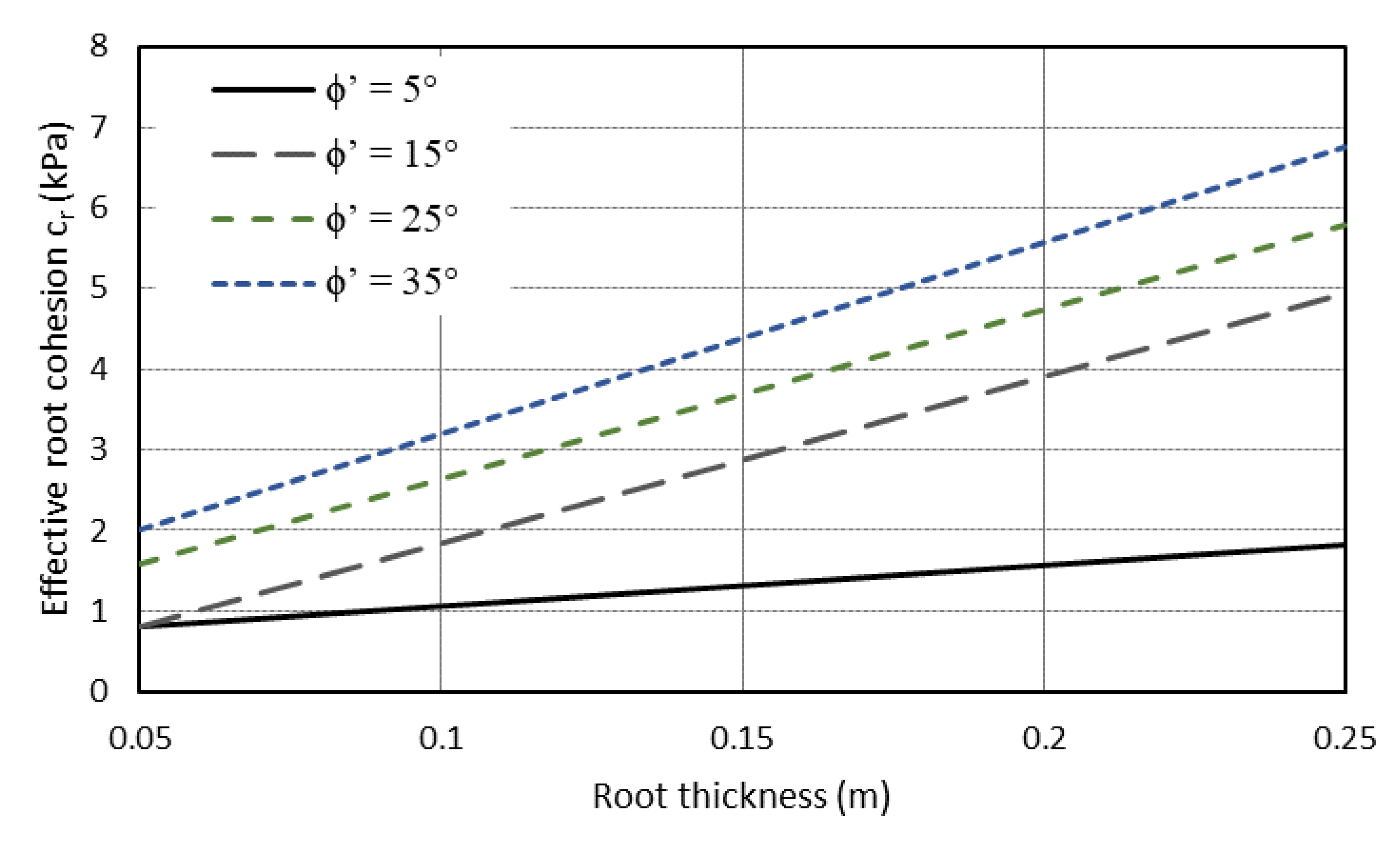
5]. Typical observations of the apparent root cohesion range from 1 kPa to 17.5 kPa.
The use of vegetation for slope reinforcement has been widely implemented for a variety of plants including grass, shrubs and trees. Although these effects have often been assessed in a qualitative manner, a number of pioneering studies were conducted in the 1960s with the purpose of quantifying the impact of vegetation on slope stability [6,7,8]. In contrast to soil cohesion, the internal friction angle remains largely unaffected by the presence of roots, due to the predominantly random orientation of root structures [9]. In many cases, root reinforcement can also reduce the formation of tension cracks in the slope surface [10,11,12]. Roots can impact a number of hydrological characteristics, including the infiltration of rainfall, run-off velocity and soil moisture content through transpiration, resulting in an increase in the soil shear strength of the soil due to increased suction [13,14,15]. Wu et al. [12] used the limit equilibrium method (LEM) to investigate forest cover and reinforcement for infinite slopes, while a number of other studies have implemented LEM-based analyses for vegetated hillslopes [16,17]. More recently, the finite element method (FEM) has been used to model apparent root cohesion [18,19]. A number of additional studies have directly modelled root structures to understand the key root features impacting numerical slope stability models [20,21,22]. Dupuy et al. [23] assessed the pull-out resistance of six categories of root morphology using two-dimensional FEM, while Mickovski et al. [24] simulated two-dimensional and three-dimensional FEM models of direct shear tests on multi-rooted soil structures. Further hybrid studies have combined both methods of analysis to investigate primary tap roots and secondary root zones through the use of root cohesion factors [25,26].
Root architectures commonly exhibit spatial variability in their composition, with each root displaying geometrical variations in depth, thickness and branching processes. Although the effects of root structure variability on a root-to-root basis is uncommon within slope stability analysis, a number of studies have quantified the characteristics of various root structures based on a set of statistical distributions [17,27,28]. In cases where the impact of root structure variability has been considered, minimal differences to slope Factors of Safety were observed when assessing constant versus linearly increasing root reinforcement with depth [29].
Often, the effects of root structures are only examined through fibre reinforcement, providing additional root cohesion [30,31]. One of the most commonly used methods of estimating root cohesion is the perpendicular root model of Wu [12] and Waldron [32] (known as the WWM), as defined by:
c r = K · t R
where K is the coefficient used to account for the random orientation of roots with respect to the slope failure plane, frequently observed between 1.0 and 1.3 [27], and t R is the mobilised root tensile strength, which can be written as:
t R = T r · a r
such that T r (kPa) defines the average root tensile strength per cross-sectional area and a r is the root area ratio (RAR) [9].
a r = A r A
where A r is the total combined cross-sectional area of the roots and A 
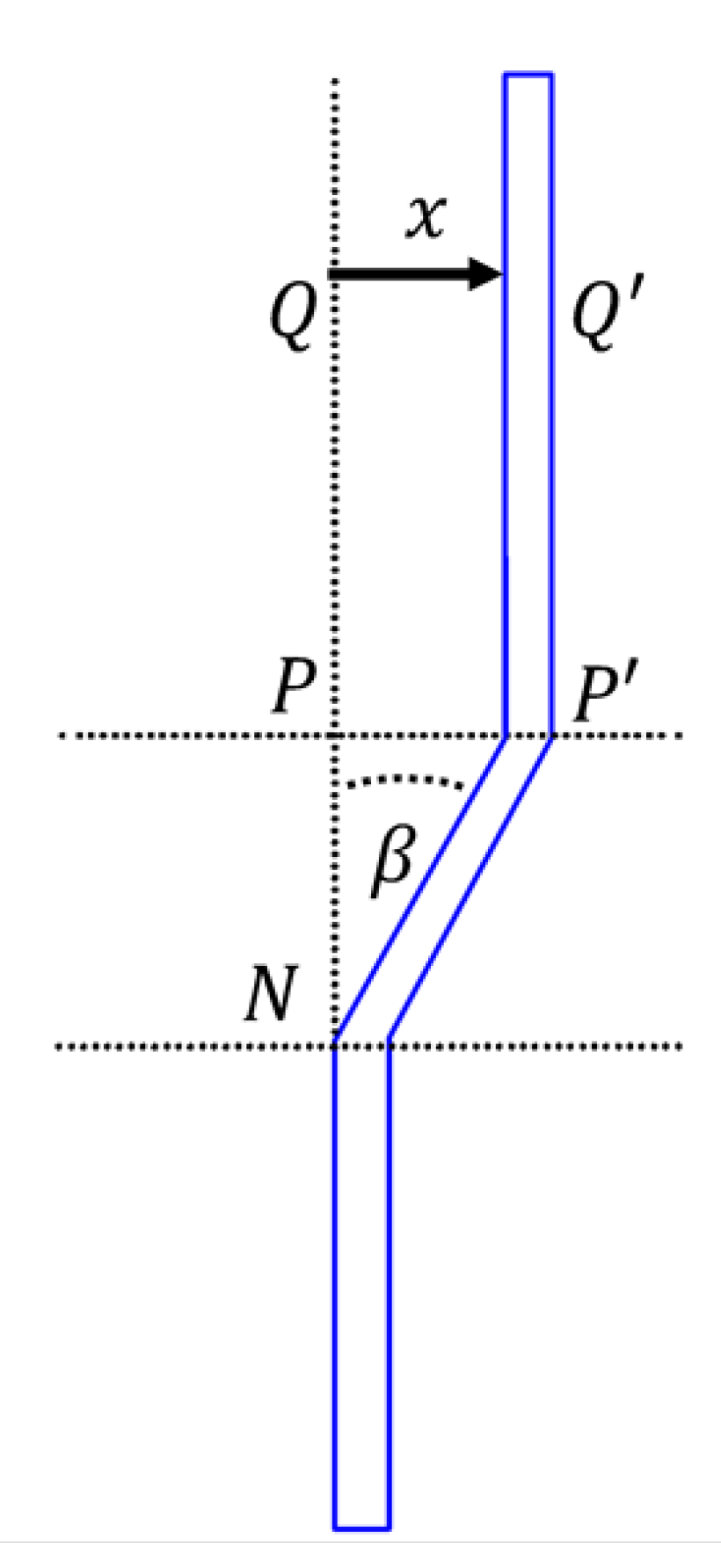
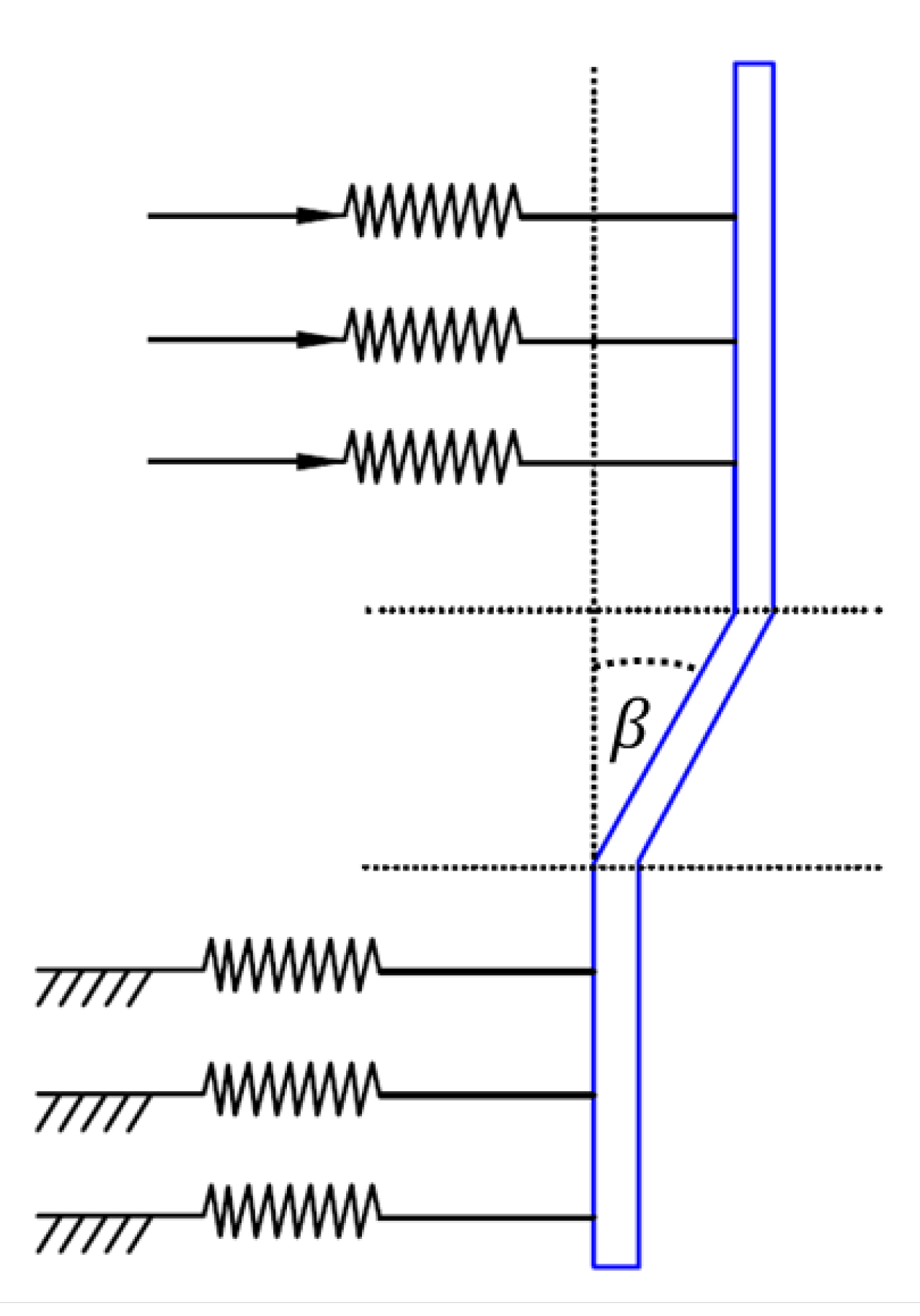
is the soil area within which the roots are considered. The WWM coefficient K 
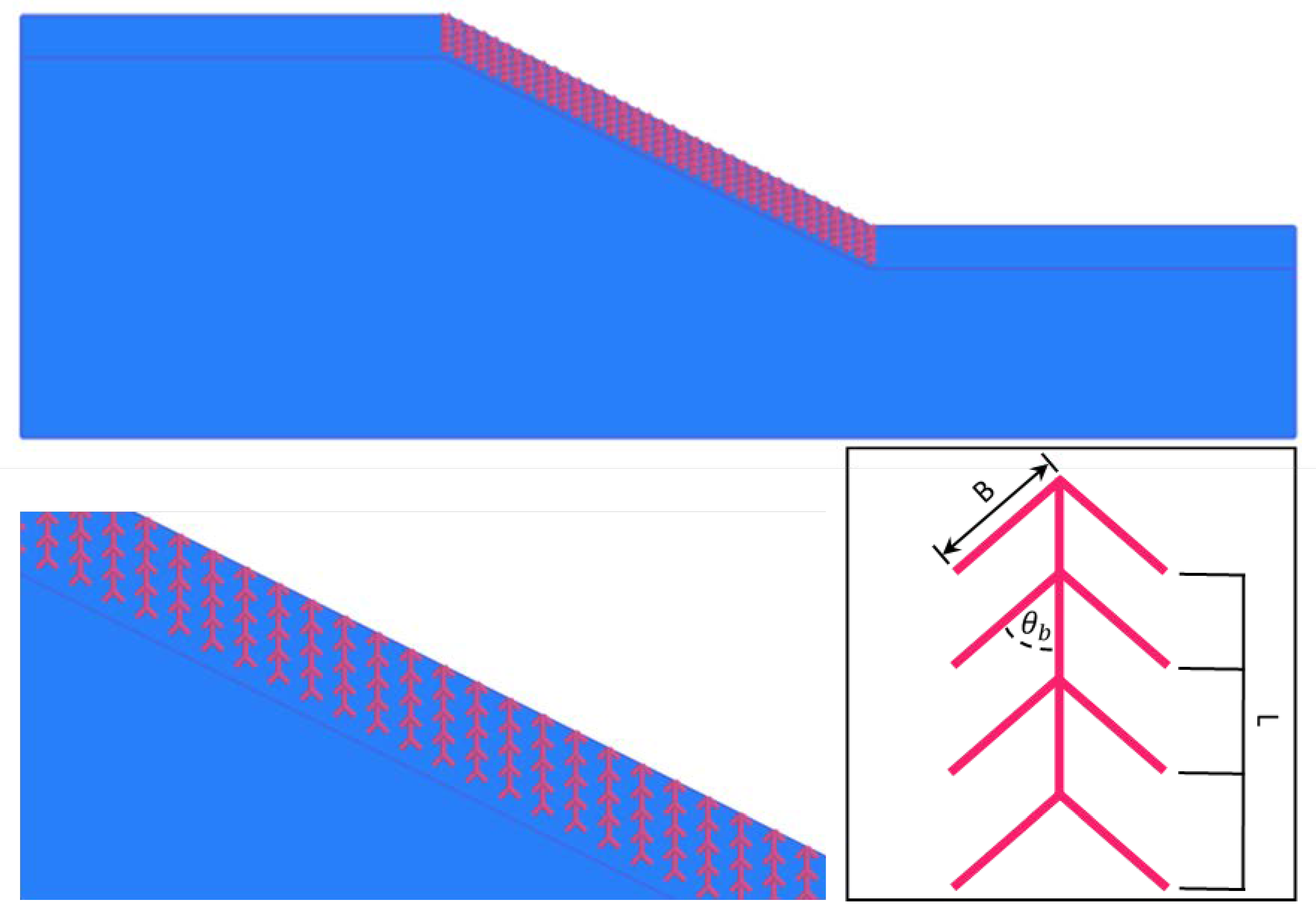
is based on the angle of the root structure β , as shown in Figure 1, where the root is displaced a distance of x , with the initial root segment N P Q , extending to a length of N P Q [33], and ϕ is the effective cohesion of the soil. K can be used to estimate the root cohesion as shown in Equation (1).
K = cos ( β ) + sin β tan ϕ
As an alternative approach to simulate root reinforcement, structural elements such as pile and beam elements can be embedded in the soil, allowing for direct simulation where roots are considered as flexural cables or bending beams. Studies have combined both methods of analysis to investigate primary tap roots and secondary root zones through the use of root cohesion factors [25,26]. This research considers FEM simulation of structural elements to model root reinforcement and topological root structures with comparisons to root cohesion FEM models presented. The results of the two model paradigms are used to develop a set of correlations between the direct simulation of root properties and associated root cohesion factors, bridging the gap between the two techniques.

2. Methodology

2.1. Finite Element Method

The finite element method was adopted to simulate the impact of root cohesion on shallow slope failure, with the geotechnical FEM package Plaxis 2D [34] chosen based on its ability to accommodate the scripting of root structural geometries. As part of the analysis, the slope FOS was determined by performing shear strength reduction (SSR) [35], whereby the original shear strength parameters defining the Mohr–Coulomb failure envelope are iteratively reduced by a strength reduction factor (SRF) until failure is observed [36].

2.2. Simulation of Apparent Root Cohesion

Extensive FEM sensitivity analyses of apparent root cohesion factors for shallow failure were conducted by Chok et al. [18], considering slope geometry, the location of vegetation and root cohesion depth, the result being a collection of stability charts. The geometry and shear strength parameters outlined by Chok et al. are shown in Figure 2 and Table 1, respectively. Figure 2 identifies the root reinforcement zone overlying the rest of the slope (with height h r ). The dimensions of the slope are calculated based on a height H. The FEM mesh distribution is shown in Figure 3, based on the geometry adopted from Chok et al. [18] with fine elements concentrated around the expected shallow failure zone. Such a concentrated mesh distribution is employed for the direct simulation of root structures for the tap root and branched root simulations to follow.
While plant roots can provide reinforcement as a result of their tensile strength and adhesional characteristics, the capacity to provide additional apparent cohesion to soils is closely linked to the composition of their root matrix [37]. Based on the species of vegetation, an increase in shear strength varying from 5 to 20 kPa can be observed [38]. Complexities in root architecture are commonly measured through the root area ratio as a means to quantify the influence of embedded root systems on the surrounding soil. Approximately 60–80% of grass-rooted vegetation is found within the top 50 mm of soil, while trees and shrubs often exhibit roots 1–3 m in depth [2]. The rooting depth and below-ground spreading geometries for a variety of species is the focus of Schenk and Jackson [39]. Based on the associated dataset, Zhu et al. [22] fitted a log-normal root length distribution with a mean and coefficient of variation of 2.2 and 0.9 m, respectively. In determining the influence of root diameters on the stiffness of combined soil–vegetation samples, Operstein and Frydman [40] presented a set of correlations based on four plant varieties. Similarly, relationships between tensile strength, root length, density and moisture content are the subject of laboratory-based studies [41]. Direct evidence suggests that root tensile strengths express significant variation as a function of root diameter [30,41]. Although in this study, the direct effects of highly variable root architectures are not assessed, the aforementioned research provides context for the variable nature of root structures.
As a baseline for comparison with the tap root and branched root models subsequently presented, a set of apparent root cohesion sensitivity analyses were conducted for the parameters of a cohesionless sand proposed by Chok et al. [18] and outlined in Table 2, varying the apparent root cohesion and the depth of the root cohesion zone for assorted friction angles. Selection of the proposed soil provides a validating case with which to consider effective root cohesion values as with the aforementioned study, providing strong agreement. Figure 4 and Figure 5 highlight the increase in slope FOS ratio (which is normalised with respect to the FOS for zero root cohesion F O S c r ) in relation to the apparent root cohesion, for the root reinforcement zone depth and friction angle, respectively, highlighting the increase due in the slope FOS due to the strength added by the apparent root cohesion. In the case of apparent root cohesion considered for various root zone depths, the trend is linear over a range of 1 kPa to 8 kPa. The spread of results is minimal for small levels of apparent root cohesion. A linear trend is also observed for all of the simulated friction angles, with all R2 coefficient of determination values in excess of 0.97, indicating strong linear trends. In both cases, the level of reinforcement provided by the apparent cohesion is increasingly pronounced with a greater root reinforcement depth and increasing friction angle. Figure 6 provides an example of the shallow failure mechanism observed for an apparent root cohesion of 4 kPa and friction angle of 15°. The geometry dimension H is equal to 10 m, with a root reinforcement depth of 2 m.

2.3. Primary Taproot Modelling

As an alternative method for modelling the stability of vegetated slopes, root structures such as primary tap roots can be directly modelled using beams and piles to represent root structures. FEM simulation of root structures can be modelled using beam elements, with the interface between the soil and structure presented through springs by a maximum force (Figure 7).
In performing a parametric study of root characteristics directly modelled through the simulation of root structures, the root parameters presented in Zhu et al. [22] were adopted (Table 3). Root structures were generated through dedicated Python code, used to define root geometry, spacing and location. Figure 8 presents a typical tap root model, with the root radius r , depth D and angle with the vertical θ presented. Tap roots are large, central root structures, which are commonly very thick and straight, growing directly downwards. Tap roots are in stark contrast to dense fibrous root systems that branch out sideways. Table 4 presents the list of root properties used to assess the variability in slope safety factor.
Figure 9, Figure 10, Figure 11 and Figure 12 present the FOS ratio with respect to root density, depth, angle, strength and thickness for a range of friction angles. The FOS ratio versus root density relationship highlighted in Figure 9 suggests that once sufficient tap root structures are present within the defined slope region, the rate at which the root structures are capable of further reinforcing the slope begins to diminish, with minimal difference between sands exhibiting internal friction angles of 15° or greater. In contrast, the FOS ratio with respect to root depth (Figure 10), angle (Figure 11), strength (Figure 12) and thickness (Figure 13) continue to increase with the friction angle over the defined range, albeit each with distinctly different profiles. While a linear trend between root depth and the FOS ratio is observed over the 2.5 m depth, the role of root angle induces significant fluctuations in the FOS ratio, which are not symmetric about the given angle. Although variation in root strength at lower friction angles signalled minimal change to the FOS ratio, a significant jump is recorded for the largest friction angle simulated. In the case of primary root thickness, equal-value increases to the FOS ratio were observed for each friction angle, based on the associated root thickness. In each case, the FOS ratio was normalised based on the first FOS value in the parameter set. The variation in root strength over the given range (Figure 12) provided only minimal contribution to the overall change in FOS, with root depth demonstrating the greatest impact on slope strength for the parameters tested. Based on the results from apparent root cohesion simulations (Section 2.2), relationships between primary tap root parameters and root cohesion were determined, using the comparative FOS values obtained from both simulation sets. The results present a simple comparison between two distinct numerical methods for root reinforcement (direct root structural parameters and apparent root cohesion), allowing apparent root cohesion models to be created based on structural root properties.
Figure 14 shows a logarithmic relationship between root density and root cohesion. For small friction angles, additional root density does not provide an appreciable amount of reinforcement; however, with an increase in friction angle, elevated levels of root cohesion are evident.
Root depth (Figure 15) and angle (Figure 16) supply the greatest amount of root cohesion for the tested parameters, with 2.5-metre roots providing nearly an additional 10 kPa compared to 0.5-metre-deep roots ( ϕ = 25 ° ). Although all root structures contribute to root reinforcement, roots with positive angles (with respect to the perpendicular) result in significantly higher safety factors than their negative-angled counterparts (note clockwise rotation denotes positive angles, as shown in Figure 8). It is of interest that over the range tested, the root tensile strength was not a significant contributor to root reinforcement, especially with lower friction angles (Figure 17). As with root depth and angle, the effective root cohesion exhibits increasing linear trends with root thickness (Figure 18).

2.4. Secondary Cohesion Modelling

The role of mechanical root reinforcement in slope stability can be modelled using both primary and secondary root structures; however, in most cases, secondary roots are largely ignored. When modelling a slope containing primary roots, secondary roots and bare soil, primary roots are often considered as a solid structural element, while secondary root zones are simulated as a root–soil composite zone [26].
The parametric study of primary and secondary root structures, with their associated impact on slope stability, is presented through a two-dimensional model (Figure 19). In keeping with the parameters used in Section 2.3, an additional secondary cohesion zone was applied through a rectangular region surrounding the primary tap root. The secondary cohesion zone surrounding the primary root is defined by R x and R y , indicating the x and y dimensions of the secondary root zone. Table 5 presents the primary/secondary root models simulated, for a root spacing of 1 metre.
Figure 20 and Figure 21 indicate the FOS sensitivity with respect to secondary root zone dimensions, while Figure 22 indicates the contribution of the secondary root cohesion value in reinforcing the slope. By incorporating a secondary root zone, a significant increase in the FOS can be observed compared to the simulation of solely a primary root structure. This is especially the case for deeper root structures due to the rapid increase in secondary root zone area with respect to root depth. Conversely, root zones exhibit minimal impact on the FOS, suggesting that such structures are not required for shallower root systems. The relationships of secondary root zone geometry and overall root cohesion are presented in Figure 23 and Figure 24. Similarly, the level of root cohesion with respect to the level of secondary root cohesion is shown in Figure 25.

2.5. Branched Root Model

Despite the simplicity of secondary root zones as a form of indirect modelling of root reinforcement, the method does not directly simulate the topological features of root systems. Figure 26 presents the branching processes considered in this study, where B is the length of each branch, θ b is the angle each root branch with respect to the horizontal and L is the number of branches. A sensitivity analysis was performed for these parameters as outlined in Table 6, with the mechanical parameters presented in Table 3.
Figure 27 highlights the relationship between the number of root branches and the slope FOS. For shallow roots, the impact of root branching is negligible. An increase to the branch length produces a largely upward linear trend in the FOS (Figure 28). The angle of branch roots has an interesting effect on slope reinforcement, with a peak FOS observed at approximately 30°; thereafter, an increase in root angle reduces the overall slope FOS (Figure 29). Figure 30 and Figure 31 display the associated root cohesion factors for the number of branch layers and the branch length, respectively.

3. Concluding Remarks

The impact of plant vegetation in providing reinforcement to shallow slopes can be assessed through several numerical techniques. When performing finite element method slope stability analysis, roots can be simulated either directly by structural elements or indirectly through apparent root cohesion factors, with each method exhibiting a range of advantages and disadvantages based on available data and model complexity.
The results detailed in this research present a comparison between three root reinforcement methods for shallow slope stability, with a sensitivity analysis identifying relationships between direct root simulation methods and apparent root cohesion values. The following salient conclusions are drawn:
(1)
The proposed method provides a mechanism of comparative assessment whereby complex root structures can be associated with a suitable effective root cohesion, exhibiting comparable deformation characteristics and slope safety factors. As a result of the method, the direct simulation of root architectures can be replaced with somewhat simplified effective root cohesion parameters, whose relationships have been provided.
(2)
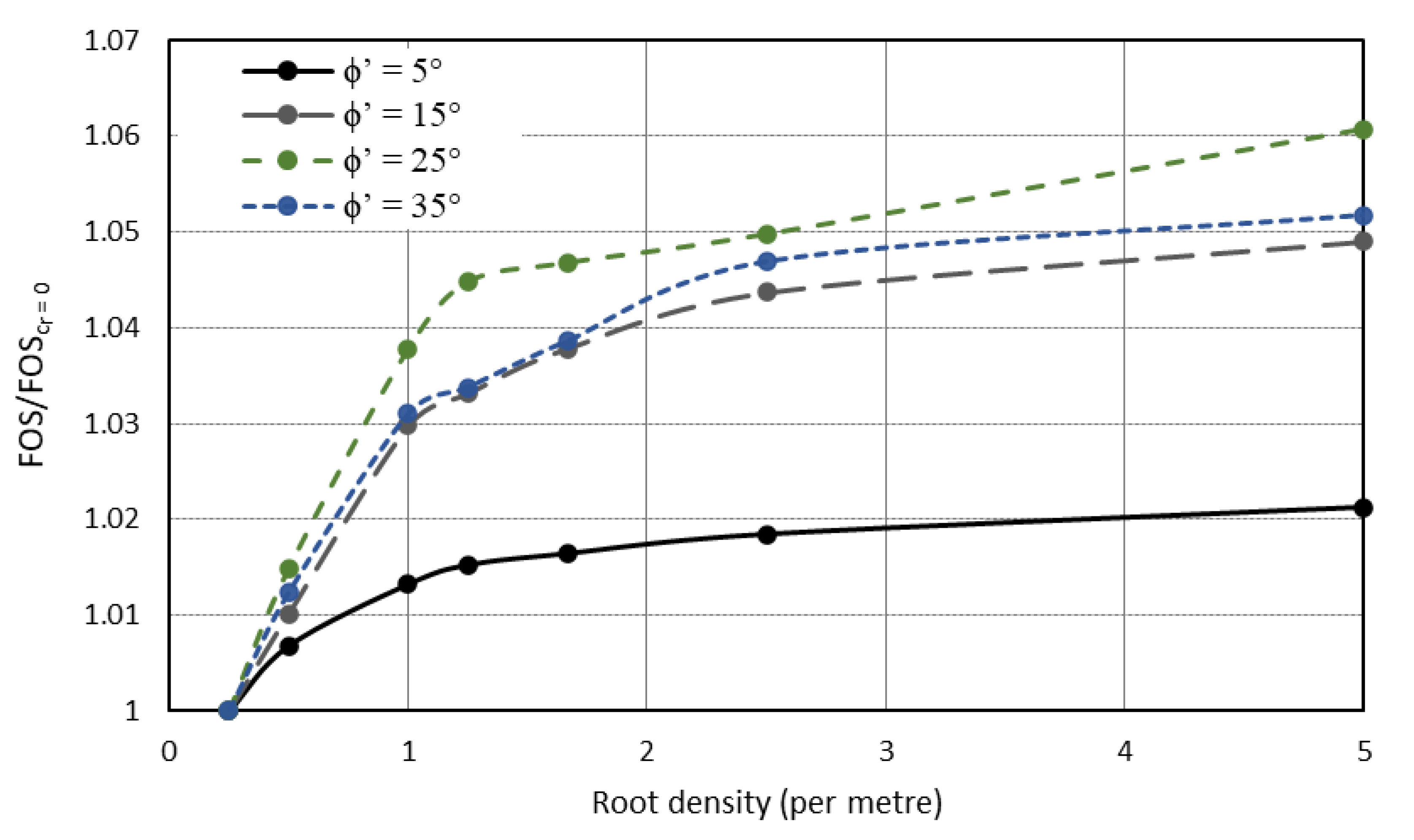
In all cases presented, the relationships were found to be either linear or logarithmic in nature, except when comparing the angles of branched root structures and apparent root cohesion values.
(3)
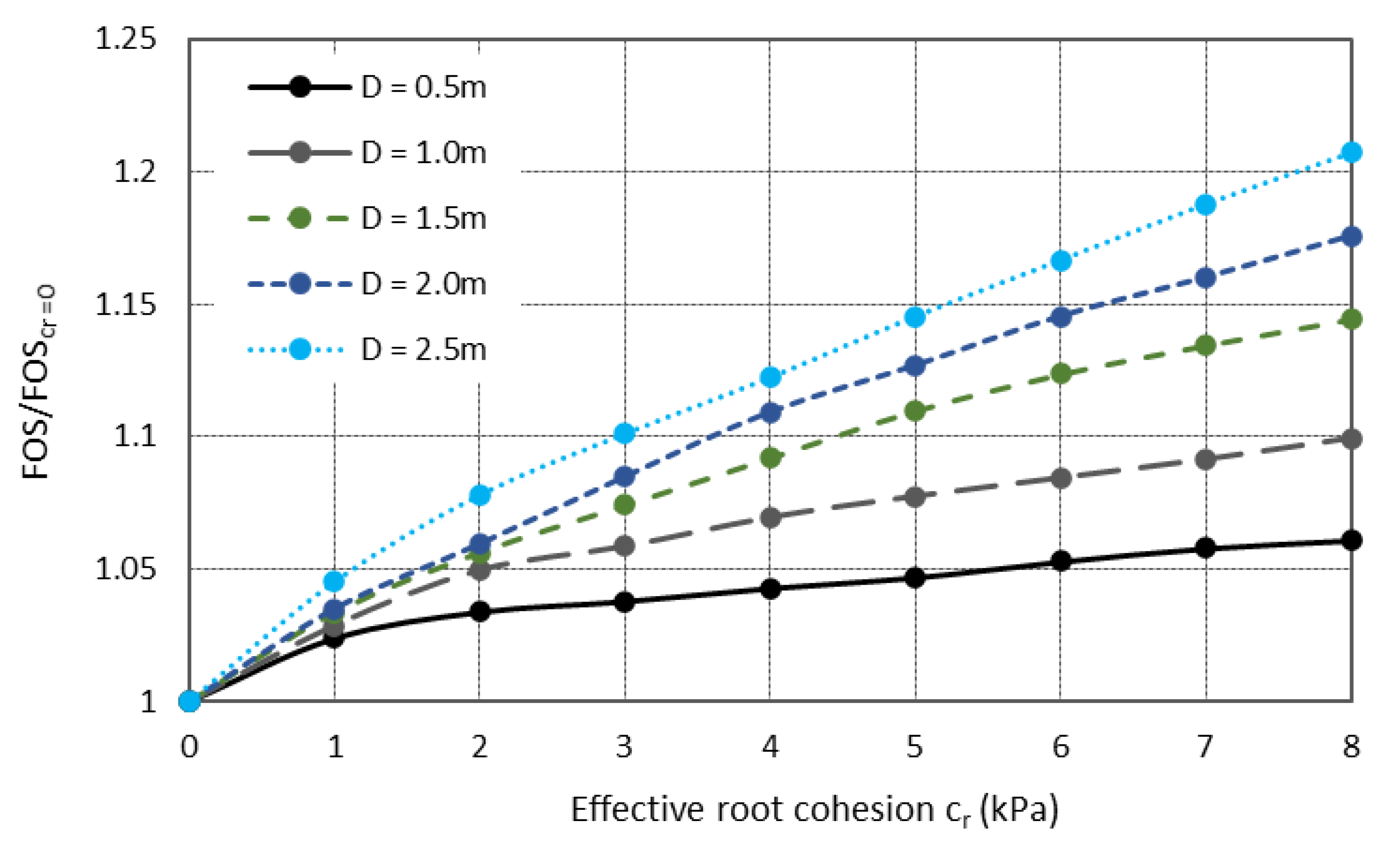
For extremely shallow root structures of the order of half a metre in depth, minimal root cohesion is provided regardless of the structural root characteristics, suggesting little benefit in modelling the roots through structural elements.
(4)
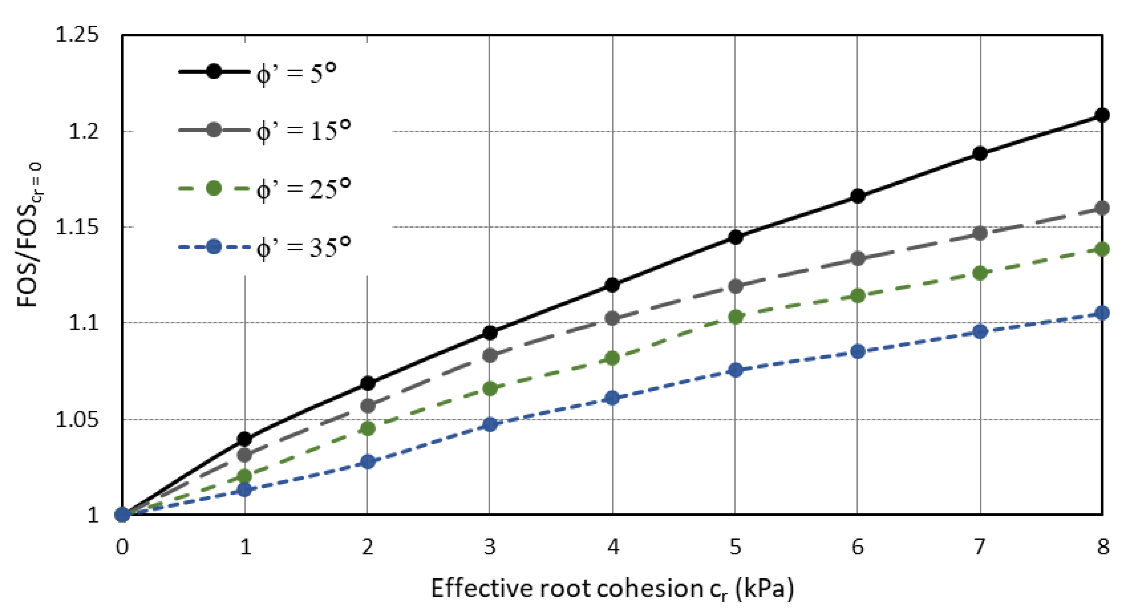
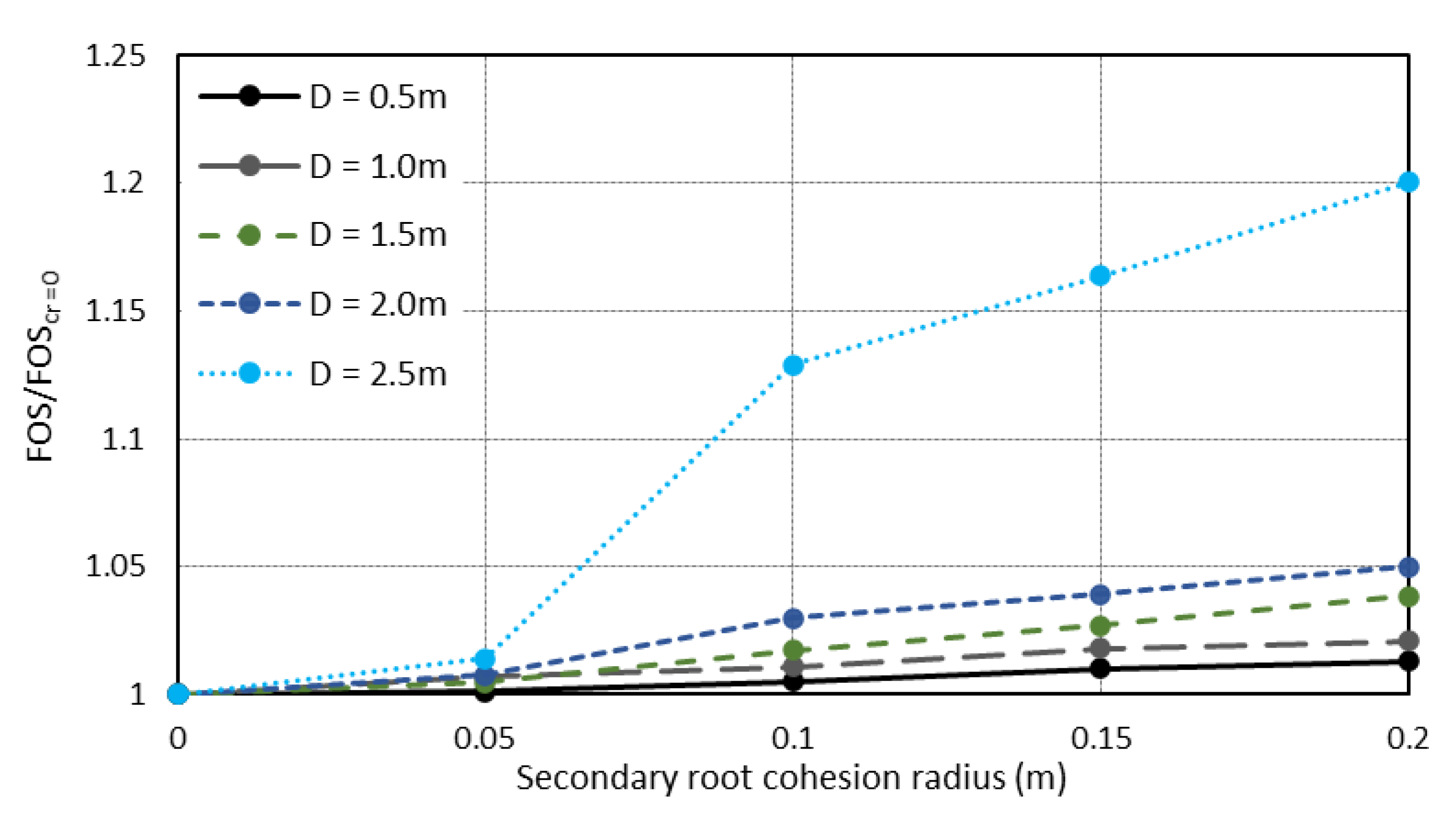
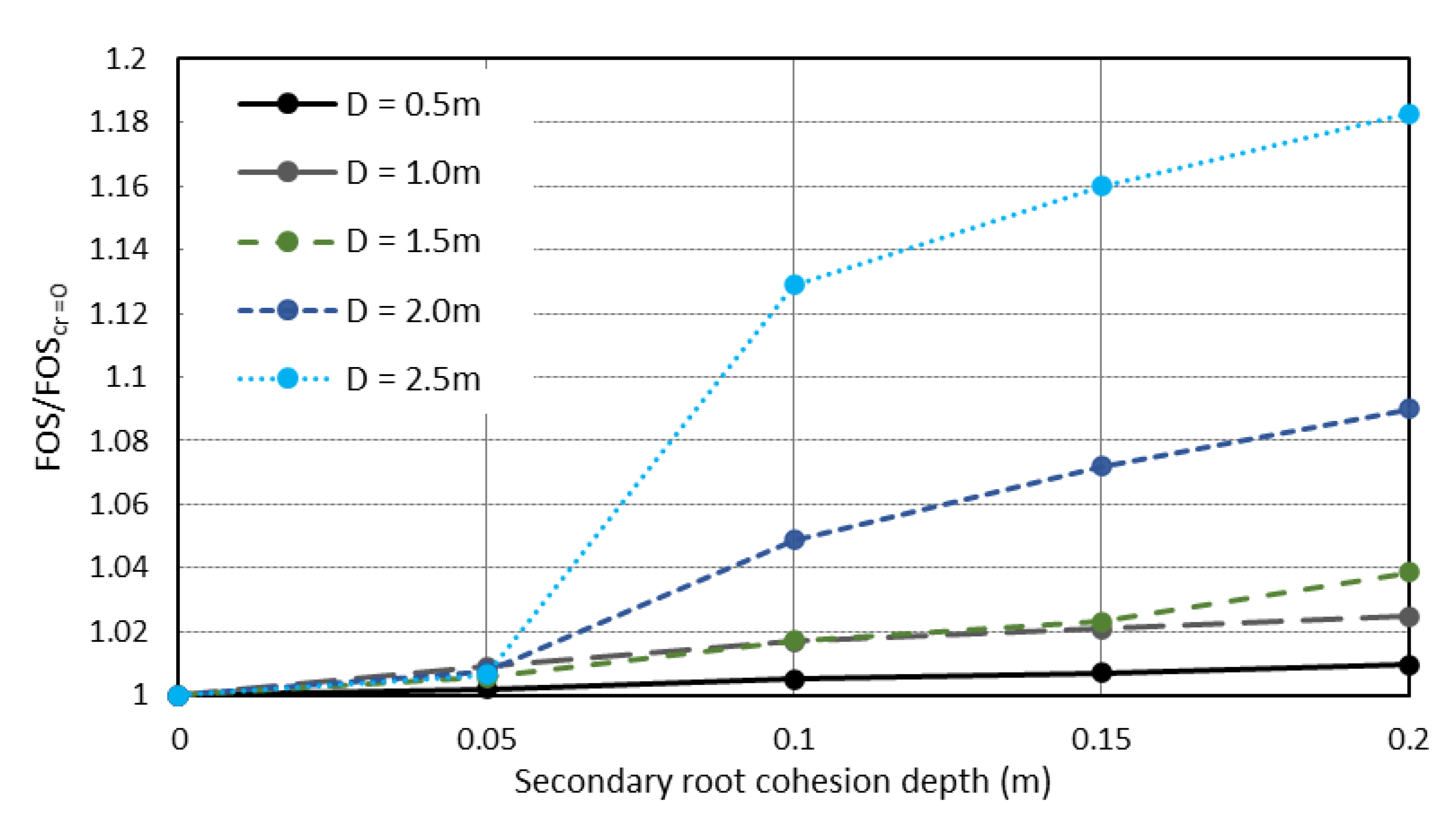
The changes in the observed FOS values for the chosen examples are often quite modest, with most FOS values of the order of 1.0 to 1.3; however, the method provides a framework that can be further extended to coupled mechanical and hydrological models.
While each numerical technique has a range of benefits and limitations, it is important to understand model performance compared with alternative methods. Limitations of the study and recommendations for future investigation are identified as follows:
(1)
The current study provides a point of comparison between effective root cohesion and direct root simulation without the presence of groundwater. In addition to the mechanical benefits in strengthening soil slopes, roots provide significant hydromechanical benefits through the uptake of groundwater, which has not been considered within the current research.
(2)
Direct simulation consists of idealised root architectures that have not taken into account the heterogeneity of root geometries. The simulation methods presented within this study can be considered as amenable to Monte-Carlo-style simulation to determine how complex, spatially variable root patterns can impact the stability of soil slopes and the associated effective root cohesion that is considered comparable to simulations involving root geometries.
(3)
While root architecture is a central focus of this research, above-ground tree and shrub structures and their toppling loads were not considered as within the scope of investigation.
(4)
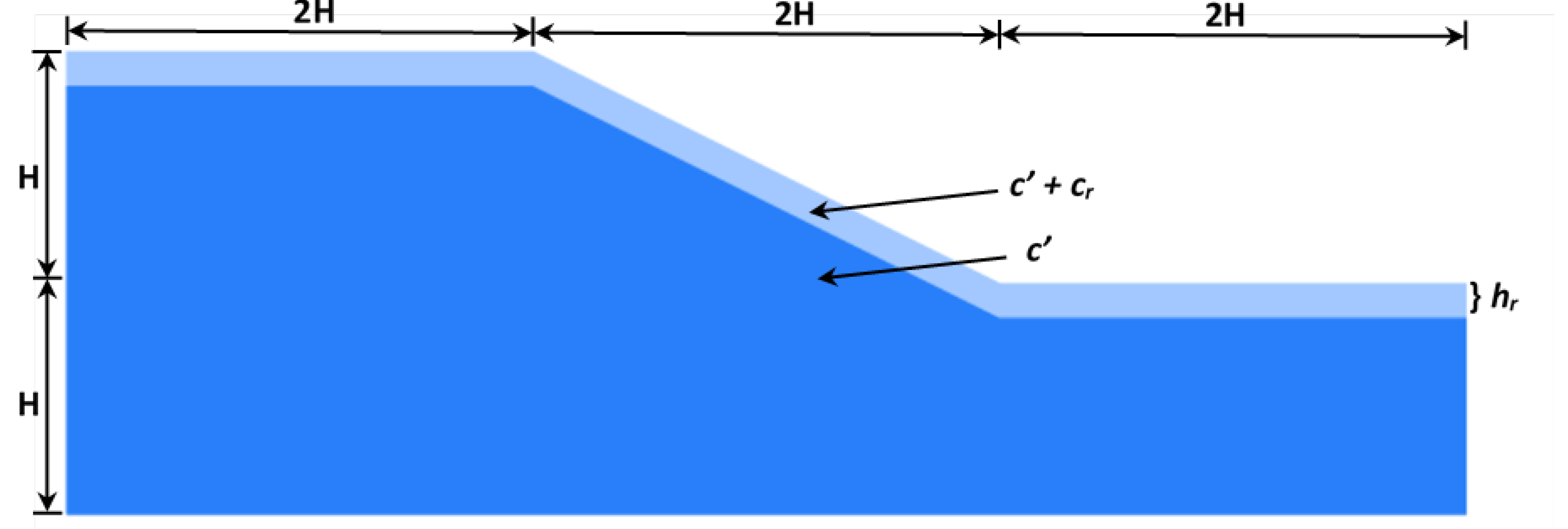
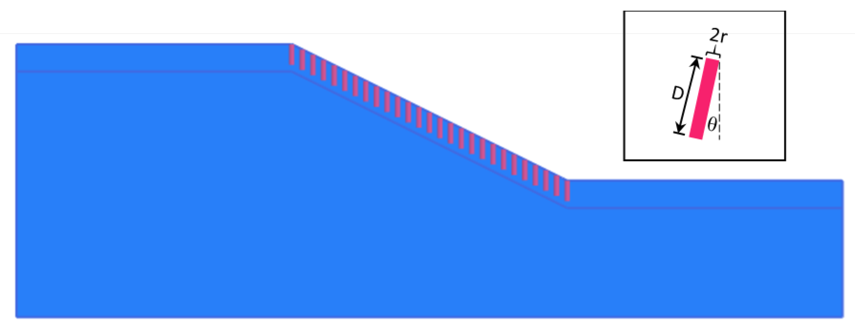
An initial single-layered slope was presented for a variety of root parameters, indicating the process whereby more complex multilayered soil layers and slope geometries may be assessed.
The developed stability charts provide a quick and easy method for comparing the mechanical performance of numerical methods for the root reinforcement of shallow slopes. Although the results presented highlight the mechanical behaviour of reinforced slopes, it is expected that further assessment of similar methods can also be extended to incorporate various aspects of vegetation hydrology and the impacts of roots on groundwater systems for complex slope geometries and a wider variety of soils.

Author Contributions

Conceptualization, A.P.D. and A.T.; methodology, A.P.D., A.T. and D.V.G.; software, A.P.D. and A.T.; validation, A.P.D. and A.T.; formal analysis, A.P.D., A.T. and D.V.G.; investigation, A.P.D., A.T. and D.V.G.; resources, A.P.D. and A.T.; data curation, A.P.D. and A.T.; writing—original draft preparation, A.P.D. and A.T.; writing—review and editing, A.P.D., A.T. and D.V.G.; visualization, A.P.D. and A.T.; supervision, A.T.; project administration, A.T.; funding acquisition, N/A. All authors have read and agreed to the published version of the manuscript.

Funding

This research received no external funding.

Data Availability Statement

Data will be made available on request.

Conflicts of Interest

The authors declare no conflict of interest.

References

  1. Galvão, T.C.d.B.; Pereira, A.R.; Parizzi, M.G.; Alves da Silva, H. Bioengineering techniques associated with soil nailing applied to slope stabilization and erosion control. Nat. Hazards Rev. 2010, 11, 43–48. [Google Scholar] [CrossRef]
  2. Greenwood, J.R.; Norris, J.; Wint, J. Assessing the contribution of vegetation to slope stability. Proc. Inst. Civ. Eng. Geotech. Eng. 2004, 157, 199–207. [Google Scholar] [CrossRef]
  3. Tsige, D.; Senadheera, S.; Talema, A. Stability analysis of plant-root-reinforced shallow slopes along mountainous road corridors based on numerical modeling. Geosciences 2020, 10, 19. [Google Scholar] [CrossRef]
  4. Gonzalez-Ollauri, A.; Mickovski, S.B. Hydrological effect of vegetation against rainfall-induced landslides. J. Hydrol. 2017, 549, 374–387. [Google Scholar] [CrossRef]
  5. Schwarz, M.; Giadrossich, F.; Cohen, D. Modeling root reinforcement using a root-failure Weibull survival function. Hydrol. Earth Syst. Sci. 2013, 17, 4367–4377. [Google Scholar] [CrossRef]
  6. Bethlahmy, N. Soil-moisture sampling variation as affected by vegetation and depth of sampling. Soil Sci. 1963, 95, 211–213. [Google Scholar] [CrossRef]
  7. Bishop, D.M.; Stevens, M.E. Landslides on Logged Areas in Southeast Alaska; US Forest Service research paper NOR;-1; United States Department of Agriculture: Washington, DC, USA, 1964.
  8. Endo, T. Effect of the Tree’s Roots upon the Shear Strength of Soil; United States Department of Agriculture: Washington, DC, USA, 1969.
  9. Gray, D.H.; Sotir, R.B. Biotechnical and Soil Bioengineering Slope Stabilization: A Practical Guide For Erosion Control; John Wiley & Sons: Hoboken, NJ, USA, 1996. [Google Scholar]
  10. Fan, C.-C.; Su, C.-F. Effect of soil moisture content on the deformation behaviour of root-reinforced soils subjected to shear. Plant Soil 2009, 324, 57–69. [Google Scholar] [CrossRef]
  11. Nakamura, H.; Nghiem, Q.; Iwasa, N. Reinforcement of tree roots in slope stability: A case study from the Ozawa slope in Iwate Prefecture, Japan. In Eco-and Ground Bio-Engineering: The Use of Vegetation to Improve Slope Stability; Springer: Dordrecht, The Netherlands, 2007; pp. 81–90. [Google Scholar]
  12. Wu, T.H.; McKinnell III, W.P.; Swanston, D.N. Strength of tree roots and landslides on Prince of Wales Island, Alaska. Can. Geotech. J. 1979, 16, 19–33. [Google Scholar] [CrossRef]
  13. Huang, B.; Nobel, P.S. Root hydraulic conductivity and its components, with emphasis on desert succulents. Agron. J. 1994, 86, 767–774. [Google Scholar] [CrossRef]
  14. Osman, N.; Barakbah, S. Parameters to predict slope stability—Soil water and root profiles. Ecol. Eng. 2006, 28, 90–95. [Google Scholar] [CrossRef]
  15. Temgoua, A.G.T.; Kokutse, N.K.; Kavazović, Z. Influence of forest stands and root morphologies on hillslope stability. Ecol. Eng. 2016, 95, 622–634. [Google Scholar] [CrossRef]
  16. Chiaradia, E.A.; Vergani, C.; Bischetti, G.B. Evaluation of the effects of three European forest types on slope stability by field and probabilistic analyses and their implications for forest management. For. Ecol. Manag. 2016, 370, 114–129. [Google Scholar] [CrossRef]
  17. Cislaghi, A.; Bordoni, M.; Meisina, C.; Bischetti, G. Soil reinforcement provided by the root system of grapevines: Quantification and spatial variability. Ecol. Eng. 2017, 109, 169–185. [Google Scholar] [CrossRef]
  18. Chok, Y.; Jaksa, M.; Kaggwa, W.; Griffiths, D. Assessing the influence of root reinforcement on slope stability by finite elements. Int. J. Geo-Eng. 2015, 6, 12. [Google Scholar] [CrossRef]
  19. Gentile, F.; Elia, G.; Elia, R. Analysis of the stability of slopes reinforced by roots. Des. Nat. V Comp. Des. Nat. Sci. Eng. WIT Trans. Ecol. Environ. 2010, 138, 189–200. [Google Scholar]
  20. Kamchoom, V.; Leung, A.K.; Ng, C.W.W. Effects of root geometry and transpiration on pull-out resistance. Géotech. Lett. 2014, 4, 330–336. [Google Scholar] [CrossRef]
  21. Norris, J.; Greenwood, J. In situ shear and pull out testing to demonstrate the enhanced shear strength of root reinforced soil. In Proceedings of the 8th International Symposium on Landslides, Cardiff, UK, 26–30 June 2000. [Google Scholar]
  22. Zhu, H.; Zhang, L.M.; Xiao, T.; Li, X. Enhancement of slope stability by vegetation considering uncertainties in root distribution. Comput. Geotech. 2017, 85, 84–89. [Google Scholar] [CrossRef]
  23. Dupuy, L.; Fourcaud, T.; Stokes, A. A numerical investigation into factors affecting the anchorage of roots in tension. Eur. J. Soil Sci. 2005, 56, 319–327. [Google Scholar] [CrossRef]
  24. Mickovski, S.B.; Stokes, A.; Van Beek, R.; Ghestem, M.; Fourcaud, T. Simulation of direct shear tests on rooted and non-rooted soil using finite element analysis. Ecol. Eng. 2011, 37, 1523–1532. [Google Scholar] [CrossRef]
  25. Li, Y.; Wang, Y.; Ma, C.; Zhang, H.; Wang, Y.; Song, S.; Zhu, J. Influence of the spatial layout of plant roots on slope stability. Ecol. Eng. 2016, 91, 477–486. [Google Scholar] [CrossRef]
  26. Ng, C.W.; Zhang, Q.; Ni, J.; Li, Z. A new three-dimensional theoretical model for analysing the stability of vegetated slopes with different root architectures and planting patterns. Comput. Geotech. 2021, 130, 103912. [Google Scholar] [CrossRef]
  27. Bischetti, G.B.; Chiaradia, E.A.; Simonato, T.; Speziali, B.; Vitali, B.; Vullo, P.; Zocco, A. Root strength and root area ratio of forest species in Lombardy (Northern Italy). In Eco-and Ground Bio-Engineering: The Use of Vegetation to Improve Slope Stability, Proceedings of the First International Conference on Eco-Engineering, Thessaloniki, Greece, 13–17 September 2004; Springer: Dordrecht, The Netherlands, 2007; pp. 31–41. [Google Scholar]
  28. Pisano, M.; Cardile, G. Probabilistic Analyses of Root-Reinforced Slopes Using Monte Carlo Simulation. Geosciences 2023, 13, 75. [Google Scholar] [CrossRef]
  29. Nguyen, T.S.; Likitlersuang, S.; Jotisankasa, A. Influence of the spatial variability of the root cohesion on a slope-scale stability model: A case study of residual soil slope in Thailand. Bull. Eng. Geol. Environ. 2019, 78, 3337–3351. [Google Scholar] [CrossRef]
  30. Abernethy, B.; Rutherfurd, I.D. The distribution and strength of riparian tree roots in relation to riverbank reinforcement. Hydrol. Process. 2001, 15, 63–79. [Google Scholar] [CrossRef]
  31. Wu, W.; Sidle, R.C. A distributed slope stability model for steep forested basins. Water Resour. Res. 1995, 31, 2097–2110. [Google Scholar] [CrossRef]
  32. Waldron, L. The shear resistance of root-permeated homogeneous and stratified soil. Soil Sci. Soc. Am. J. 1977, 41, 843–849. [Google Scholar] [CrossRef]
  33. Waldron, L.; Dakessian, S. Soil reinforcement by roots: Calculation of increased soil shear resistance from root properties. Soil Sci. 1981, 132, 427–435. [Google Scholar] [CrossRef]
  34. Brinkgreve, R.; Kumarswamy, S.; Swolfs, W.; Waterman, D.; Chesaru, A.; Bonnier, P. PLAXIS 2016; PLAXIS Company (Plaxis bv): Delft, The Netherlands, 2016. [Google Scholar]
  35. Griffiths, D.; Lane, P. Slope stability analysis by finite elements. Geotechnique 1999, 49, 387–403. [Google Scholar] [CrossRef]
  36. Dyson, A.P.; Tolooiyan, A. Optimisation of strength reduction finite element method codes for slope stability analysis. Innov. Infrastruct. Solutions 2018, 3, 38. [Google Scholar] [CrossRef]
  37. Coppin, N.J.; Richards, I.G. Use of Vegetation in Civil Engineering; Butterworths: Ciria, Spain, 1990. [Google Scholar]
  38. Gray, D.H.; Leiser, A.T. Biotechnical Slope Protection and Erosion Control; Van Nostrand Reinhold Company Inc.: New York, NY, USA, 1982. [Google Scholar]
  39. Schenk, H.J.; Jackson, R.B. Rooting depths, lateral root spreads and below-ground/above-ground allometries of plants in water-limited ecosystems. J. Ecol. 2002, 90, 480–494. [Google Scholar] [CrossRef]
  40. Operstein, V.; Frydman, S. The influence of vegetation on soil strength. Proc. Inst. Civ. Eng. Ground Improv. 2000, 4, 81–89. [Google Scholar] [CrossRef]
  41. Ali, F. Use of vegetation for slope protection: Root mechanical properties of some tropical plants. Int. J. Phys. Sci. 2010, 5, 496–506. [Google Scholar]
Figure 1. WWM model of a disturbed, flexible root, adapted from Waldron and Dakessian [33].
Geotechnics 03 00016 g001
Figure 2. Slope geometry adopted from Chok et al. [18].
Geotechnics 03 00016 g002
Figure 3. FEM mesh.
Figure 3. FEM mesh.
Geotechnics 03 00016 g003
Figure 4. FOS ratio versus effective root cohesion for different depths of the root reinforcement zone.
Geotechnics 03 00016 g004
Figure 5. FOS ratio versus root effective cohesion for different friction angles.
Geotechnics 03 00016 g005
Figure 6. Slope failure surface for an apparent root cohesion of 4 kPa, friction angle of 15° and root reinforcement depth of 2 m.
Geotechnics 03 00016 g006
Figure 7. Embedded beam row bended root model.
Geotechnics 03 00016 g007
Figure 8. Slope model incorporating tap root structures.
Geotechnics 03 00016 g008
Figure 9. FOS ratio versus root density.
Geotechnics 03 00016 g009
Figure 10. FOS ratio versus root depth.
Geotechnics 03 00016 g010
Figure 11. FOS ratio versus root angle.
Geotechnics 03 00016 g011
Figure 12. FOS ratio versus root strength.
Geotechnics 03 00016 g012
Figure 13. FOS ratio versus primary root thickness.
Geotechnics 03 00016 g013
Figure 14. Effective root cohesion vs. root density.
Geotechnics 03 00016 g014
Figure 15. Effective root cohesion versus root depth.
Geotechnics 03 00016 g015
Figure 16. Effective root cohesion versus root angle.
Geotechnics 03 00016 g016
Figure 17. Effective root cohesion versus root strength.
Geotechnics 03 00016 g017
Figure 18. Effective root cohesion versus root thickness.
Geotechnics 03 00016 g018
Figure 19. Secondary cohesion model geometry.
Geotechnics 03 00016 g019
Figure 20. FOS ratio versus secondary root cohesion radius.
Geotechnics 03 00016 g020
Figure 21. FOS ratio vs. secondary root cohesion depth.
Geotechnics 03 00016 g021
Figure 22. FOS ratio versus secondary root cohesion.
Geotechnics 03 00016 g022
Figure 23. Effective root cohesion versus secondary root cohesion radius.
Geotechnics 03 00016 g023
Figure 24. Effective root cohesion versus secondary root cohesion depth.
Geotechnics 03 00016 g024
Figure 25. Effective root cohesion versus secondary root cohesion.
Geotechnics 03 00016 g025
Figure 26. Branched root model geometry.
Geotechnics 03 00016 g026
Figure 27. FOS ratio versus number of branch layers ( L ).
Geotechnics 03 00016 g027
Figure 28. FOS ratio versus branch length ( B ).
Geotechnics 03 00016 g028
Figure 29. FOS ratio versus branch angle ( θ b ).
Geotechnics 03 00016 g029
Figure 30. Effective root cohesion versus number of branches.
Geotechnics 03 00016 g030
Figure 31. Root cohesion versus root branch length (branch angle θ b = 30 ° ).
Geotechnics 03 00016 g031
Table 1. Geotechnical input parameters of a cohesionless sand as adopted from Chok et al. [18].
Input VariableValue(s)
Elastic modulus (E, kN/m2) 50 × 10 3
Poisson’s ratio (ν)0.2
Unit weight (γ, kN/m3)20
Table 2. Input variables and values for root cohesion parametric studies undertaken.
Input VariableValue(s)
Effective root cohesion ( c r , kN/m2)0, 1, 2, 3, 4, 5, 6, 7, 8
Root cohesion zone depth (m)0.5, 1, 1.5, 2, 2.5
Effective friction angle ( ϕ , °)5, 15, 25, 35
Table 3. Root parameters adopted from Zhu et al. [22].
ParameterSymbolValue
Root pull-out resistanceP (kN/m)2.5
Root tensile capacityT (kN)12.5
Root shear capacityQ (kN)6.25
Table 4. Input variables and values for tap root parametric studies undertaken.
Input VariableValue(s)
Root strength (kN)6.5, 9.5, 12.5, 15.5, 23.5
Root thickness (m)0.05, 0.1, 0.15, 0.2, 0.25
Root spacing (m)0.25, 0.5, 1, 1.25, 1.67, 2.5, 5
Friction angle (ϕ′, °)5, 15, 25, 35
Root depth (m)0.5, 1, 1.5, 2, 2.5
Table 5. Input variables and values for secondary cohesion parametric studies undertaken.
Input VariableValue(s)
Secondary root cohesion (kPa)1, 2, 3, 4
Secondary root cohesion radius (m)0.05, 0.1, 0.15, 0.2
Secondary root cohesion depth (m)0.05, 0.1, 0.15, 0.2
Table 6. Input variables and values for branched root parametric studies undertaken.
Input VariableValue(s)
Branch length B (m)0.05, 0.1, 0.15, 0.2, 0.25, 0.3
Branch angle θ b (°)15, 30, 45, 60
Number of branch layers L 1, 2, 3, 4
Disclaimer/Publisher’s Note: The statements, opinions and data contained in all publications are solely those of the individual author(s) and contributor(s) and not of MDPI and/or the editor(s). MDPI and/or the editor(s) disclaim responsibility for any injury to people or property resulting from any ideas, methods, instructions or products referred to in the content.

