Article

Using Kiln Dust to Improve Weak Subgrades for Pavement Construction: A Field Verification in Michigan, USA

1
Department of Civil and Architectural Engineering, Lawrence Technological University, Southfield, MI 48075, USA
2
Independent Researcher, Bloomfield Hills, MI 48301, USA
3
Arcadis, Seattle, WA 98101, USA
4
Soil and Materials Engineers, Inc., Plymouth, MI 48170, USA
*
Author to whom correspondence should be addressed.
Geotechnics 2023, 3(2), 179-192; https://doi.org/10.3390/geotechnics3020011
Submission received: 31 December 2022 / Revised: 17 February 2023 / Accepted: 8 April 2023 / Published: 11 April 2023

Abstract

:
Remove-and-replace with suitable material has been the primary solution used for improving subgrades in Michigan, USA, when weak subgrades are encountered in road construction. Considering the large extent of silty and clayey soils found in southeastern Michigan, where much of the population and the roads are located within the state, the earthwork associated with this solution is massive and expensive. The use of cement kiln dust (CKD) or lime kiln dust (LKD) as a subgrade stabilizer can be a cost-effective solution if there is sufficient evidence to prove that such stabilization is suitable for the soils and the climate in southeastern Michigan. This became the subject of a field and laboratory investigation carried out in Michigan and sponsored by the Michigan Department of Transportation. The findings from the laboratory portion of this research (which were published in a separate manuscript) proved CKD’s suitability for long-term stabilization and LKD’s capacity for being a stabilizer for short-term modifications of clayey soils found in southeastern Michigan. This study covers the field testing portion of this investigation. Two CKD-stabilized and another two LKD-stabilized subgrades, which were already in use for 4–6 years, were tested for strength, using dynamic cone penetration (DCP) tests. The California bearing ratios estimated from the DCP tests showed that the CKD-stabilized and LKD-stabilized subgrades could offer strength gains as high as 200–515% and 149–257% compared to in situ soils, respectively, even after 4–6 years in use.

1. Introduction

Silty and clayey soils that are encountered in Michigan often pose design and constructability challenges in road construction projects. Remove-and-replace with suitable material, which is known as undercutting, has been the usual solution for such a weak subgrade. The earthwork volume involved in undercutting is very large, given the large extent of the road network that spans over weak soils that the Michigan Department of Transportation (MDOT) is required to maintain, especially in the more populous southeastern part of the state. Based on the 2022 Asset Management Plan of the MDOT, the southeastern part of the state has 71.3% of the lane miles [1], and mostly consists of wet loamy subgrade soils [2]. This issue has made the MDOT look for other efficient solutions such as mechanical stabilization, increase in base thickness, or chemical stabilization to stabilize weak subgrade.
Chemical stabilization is a method that can be used for enhancing the strength of weak subgrades [3]. Depending on the expected outcome, the chemical materials used in subgrade strength improvement are divided into two categories, stabilizers and modifiers. The chemicals used to achieve long-term strength, uniformity, and durability of the subgrade are called stabilizers, and the chemicals used to achieve short-term strength to limit deflections from heavy construction traffic are called modifiers [4]. For ease of presentation, this study uses the word stabilizer to define both stabilizers and modifiers. Cement and lime are the most widely used substances for chemical stabilization, and both can act as stabilizers as well as modifiers, depending on the application rate and the properties of the soil being strengthened.
On a few occasions in the past, cement and lime stabilization have been used in Michigan to strengthen weak subgrades [5]. However, the stabilizers used for cement and lime stabilization (i.e., Portland cement and quicklime) are both relatively expensive, as they are commercially manufactured materials that have many other established industrial uses. When road construction projects cannot acquire them at competitive prices, higher project costs are inevitable. However, if alternative materials are available, the price point can become more competitive with the various pavement design options.
The soil strength increase that happens during lime stabilization is predominantly due to the pozzolanic reaction initiated by calcium oxide in lime [6]. On the other hand, in cement stabilization, soil strength gain is afforded through the hydration of cement particles [6]. What this suggests is that even industrial byproducts such as cement kiln dust (CKD) and lime kiln dust (LKD) should qualify as stabilizers if they have enough cementitious materials or calcium oxide in them, respectively. Fortunately, LKD and CKD both usually have appreciable amounts of calcium oxide or cementitious materials, respectively.
Although industrial byproducts such as CKD and LKD can be cost-effective alternatives to cement or lime stabilizers, their usage has not become popular yet due to the lack of adequate data from testing [7]. In the past twenty to twenty-five years, only a handful of research projects and practical applications of CKD and LKD in soil stabilization have been reported in the literature. Due to the same reasons, such methods have yet not reached the level of support to be included in most state or federal road construction guidelines. Considering the local availability of these materials in Michigan, an MDOT-sponsored laboratory and field research investigation was conducted in Michigan during September–November, 2014. During the laboratory investigation, the suitability of using CKD and LKD as well as fly ash as subgrade stabilizers were tested for three different subgrades that are often encountered in southeastern Michigan. The results from this laboratory investigation, published by Bandara et al. [8], proved CKD’s suitability as a subgrade stabilizer. The same laboratory investigation also revealed that LKD is more suitable, in general, to be used as a subgrade modifier.
During the field investigation that was conducted in parallel to the laboratory investigation described in Bandara et al. [8], four road segments were evaluated, whose subgrades were previously stabilized, either with CKD or LKD, and have been in service for 4 to 6 years. The objective of the field investigation was to verify the suitability of CKD and LKD as stabilizers. This was investigated based on dynamic cone penetrometer (DCP) testing. In this context, this study is devoted to describing the above-mentioned field-testing program that was conducted in 2015, and the results obtained from the testing. Synthesizing the results of the performance of CKD and LKD, as stabilizers in Michigan road construction and recent field investigations reported in the literature, provides support to the current understanding of their usage.

2. Background

Although chemical stabilization of subgrade is not a new topic in road construction, the interest has been largely devoted to the use of lime or cement as the stabilization material [9,10,11]. The use of industrial byproducts such as CKD and LKD in soil stabilization has only gained attention recently, which has been due to economic and resource scarcity issues [8]. According to a National Cooperative Highway Research Program (NCHRP) report published in 2013 [7], only 11 states were using CKD as a subgrade stabilizer, and only 3 states were using a combination of CKD/LKD as a subgrade stabilizer for highway applications. Another study that was published a year later, sponsored by the Ohio Department of Transportation, reported the number of states using kiln dust (both CKD and LKD) in subgrade stabilization as five [12]. However, it must be noted that this study from Ohio was based on the responses received from 26 states. Therefore, this study may have missed a few states that were using CKD or LKD as a stabilizer. A conclusion from these limited data is that the use of CKD and LKD in subgrade stabilization has yet to become popular. This also explains the limited presence of related literature found in the public domain. Even among the scant available literature, the majority of them describe laboratory studies [7,11,13,14], and there are only a few publications that describe field use applications. The studies that describe field applications are briefly discussed in chronological order in the next few paragraphs.
Miller et al. [15] conducted both field and laboratory studies to evaluate the suitability of CKD as a soil stabilizer. The performance of CKD obtained from three different cement manufacturers was compared with the performance of quicklime. Fieldwork involved the construction of test sections along a rural highway in Oklahoma. Treated soil samples were collected from the field to carry out unconfined compression testing in the laboratory. In situ testing included DCP testing of the stabilized subgrade and falling weight deflectometer testing (FWD) on the completed pavement surface. Chemical testing was conducted to determine the chemical makeup of each type of CKD, and soil–CKD mixtures were tested for pH response. Chemical tests on the CKD and CKD–soil mixtures revealed aspects of the CKD composition that can be correlated with the degree of stabilization. Regarding strength improvements, results showed that CKD from one cement plant performed significantly better than lime and CKD from other plants. The laboratory and field test data showed that CKD was more effective in stabilizing soil in general compared to quicklime. Additional laboratory tests showed that the influence of CKD and lime on the plasticity index of soils was similar, and that both additives imparted some resistance to freeze–thaw and wet–dry cycles. Observations indicated that the treatment with CKD can be cost-effective, and that it requires less construction time than treatment with quicklime.
In 2008, a field evaluation of subgrades stabilized with LKD and lime was conducted for the Indiana Department of Transportation [16]. In this research project, five pavement sections with LKD-stabilized subgrades and one pavement section with lime-stabilized subgrade were evaluated. The LKD-stabilized subgrades were stabilized with 5% LKD by weight, and the lime-stabilized subgrade was stabilized with 4% lime by weight. When the field evaluation was performed, LKD-stabilized pavement sections were in service for 6–12 years after construction, and the lime-stabilized pavement section was in service for 6 years after construction. The field evaluation also consisted of DCP testing at two sites and FWD testing at all six sites, with 20 FWD tests being conducted within each site. Back calculation of layer moduli was conducted using the FWD data to estimate the in situ subgrade layer moduli and stabilized subgrade layer moduli. The DCP test data were used to determine the in situ California bearing ratio (CBR) of the underlying in situ subgrade soils and stabilized soils. The results showed that the stabilized subgrade retained strength, even after 6–12 years after construction.
Another study conducted by Li et al. [17] evaluated the field calibration of fatigue models of cementitiously stabilized pavement materials for use in mechanistic–empirical pavement design [17]. The models chosen for field calibration in this study were the ones from the Mechanistic–Empirical Pavement Design Guide (MEPDG) by the American Association of State Highway and Transportation Officials (AASHTO). The field calibration data were obtained from previous literature and previous field experiments conducted by the research team. Some of the projects were used for calibrating freeze–thaw damage and wet–dry damage models. The moduli of the stabilized layers were back-calculated from the FWD data. However, of the 17 field evaluation projects, only one project was stabilized with CKD; all of the other projects were stabilized with either fly ash, cement, or lime. One important procedure used in this study to evaluate the effect of the number of freeze–thaw cycles on the stabilized layer was the use of MEPDG software to model the freeze–thaw cycles using local climatic data. The MEPDG software can establish the freezing depth and the thawing depth, and based on the timing of these depths, the number of freeze–thaw cycles can be determined during the life of the pavement. Although FWD data were used to evaluate the modulus of the stabilized layer at different service intervals of the project, larger errors were observed during back calculation due to the nature of the pavement structure (i.e., granular base sandwiched between hot-mix asphalt (HMA) and the stabilized layer).
A study conducted by Rothhamel et al. [18] evaluated the performance of hydraulic binders for soil stabilization of fine-grained soils in cold environments. In this study, two types of hydraulic binders were evaluated for soil stabilization, Petrit T, a by-product from sponge iron production, and MultiCem, a 50% and 50% combination of Portland Cement and CKD. Using a laboratory investigation program, a multiple linear regression model was developed to estimate the unconfined compressive strength (UCS) of stabilized samples with other independent variables such as binder content, days of curing before freeze–thaw, 12 freeze–thaw cycles, days of curing after freeze–thaw, and water content.

3. Materials and Methods

The long-term performance of pavements constructed on chemically stabilized subgrades can only be assessed using field data where the pavement has been subjected to realistic environmental and traffic conditions. Therefore, for this research project, a few pavement sections where the subgrade was stabilized with CKD or LKD located in Michigan and Ohio were selected for evaluation. Since stabilization affects the strength, uniformity, and freeze–thaw durability of the subgrade, the DCP test was the method chosen to evaluate the long-term performance of the subgrade. The details of the site selection, as well as the testing methodology, are presented in the following subsections.

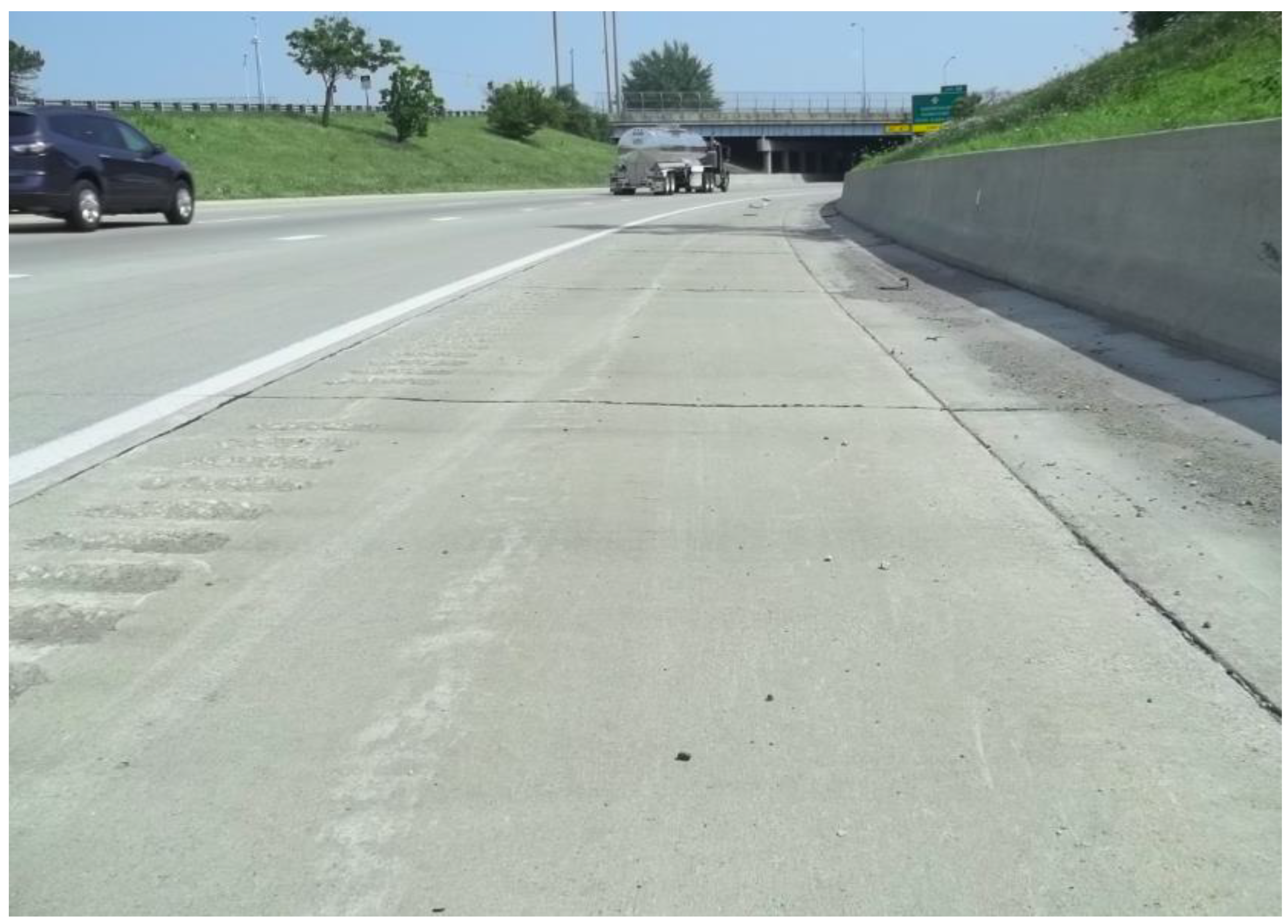
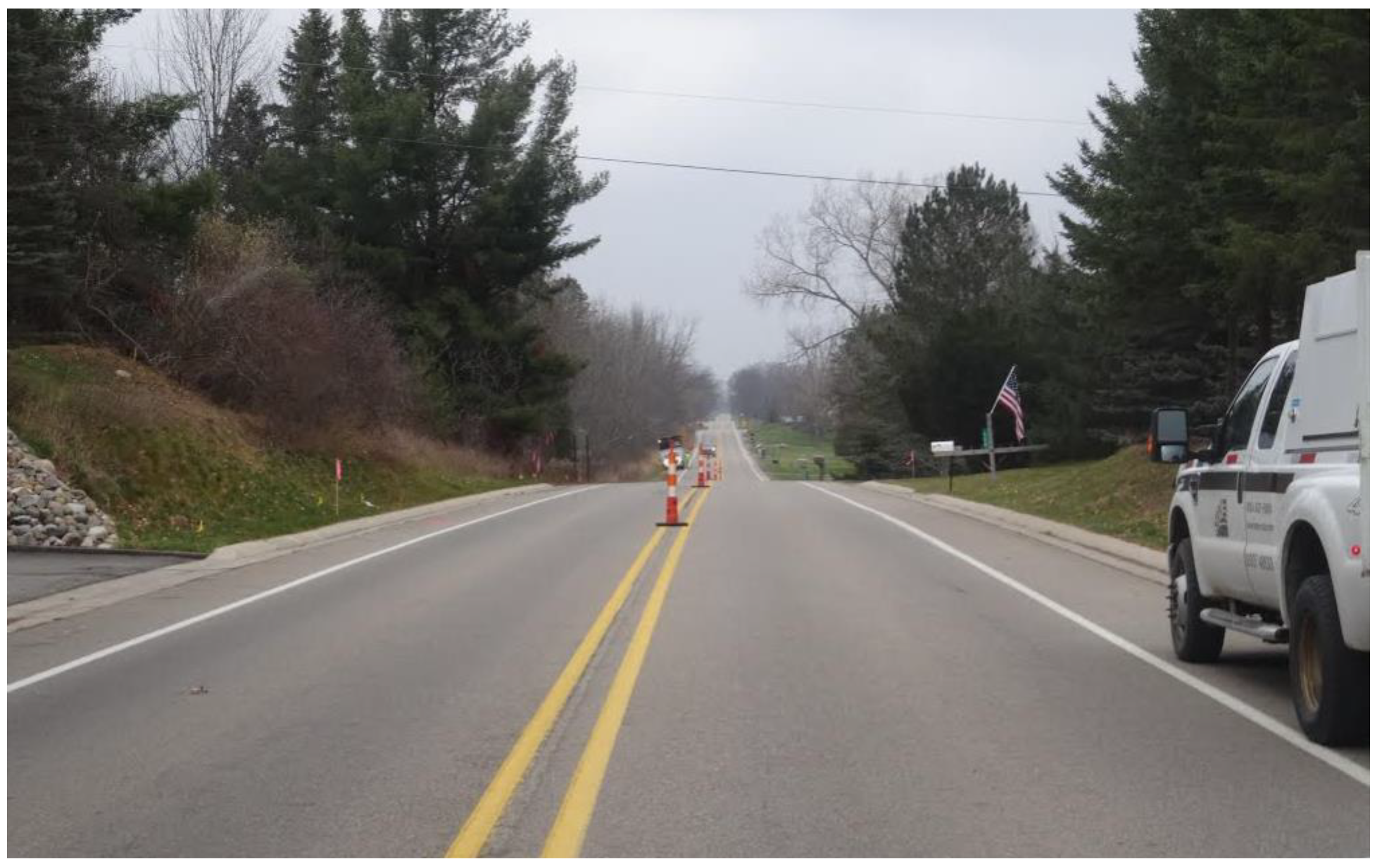
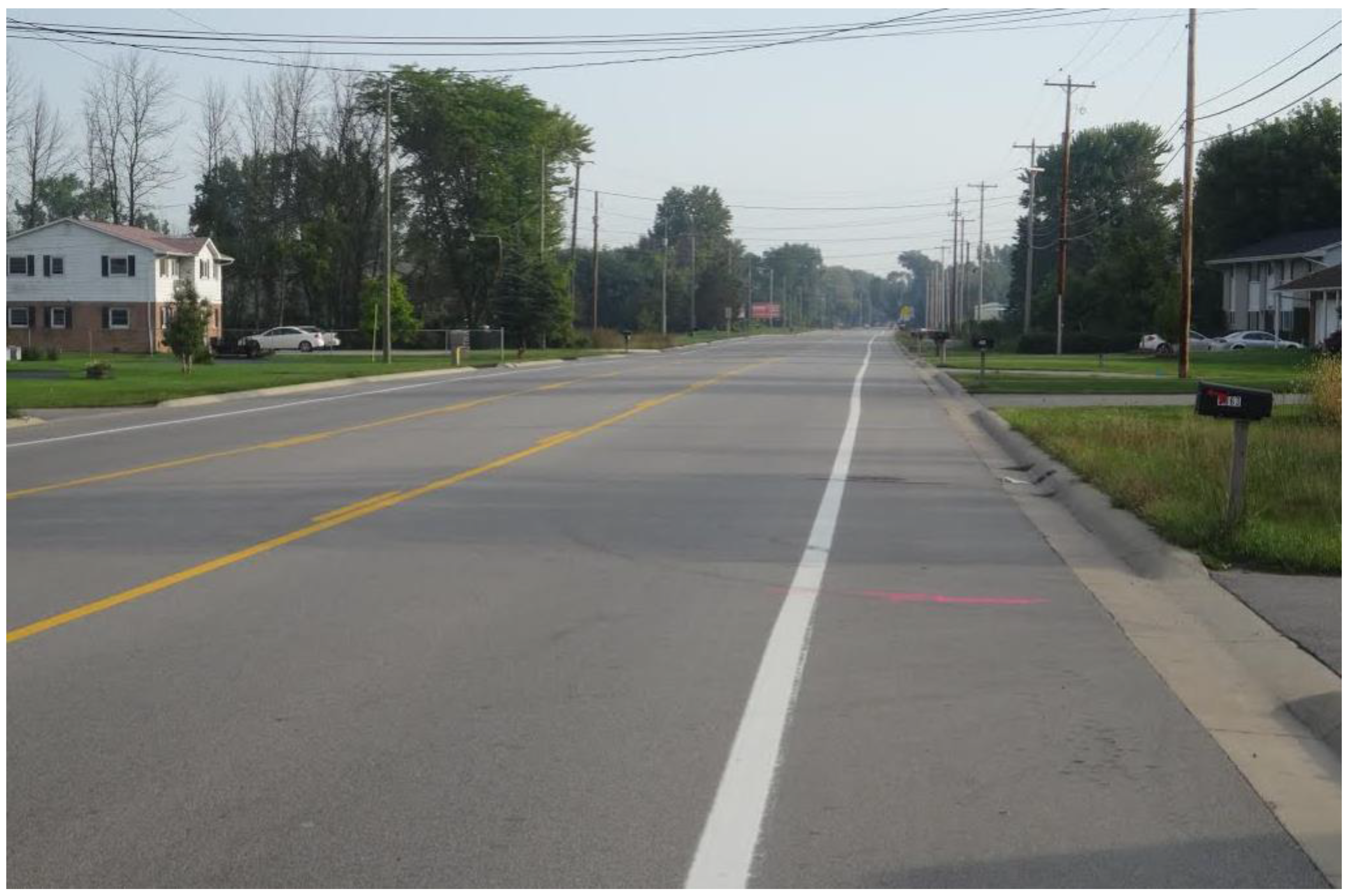
3.1. Site Selection for Field Testing

The MDOT has carried out only a handful of subgrade stabilization projects on state highways. Therefore, during our site selection process for field evaluation, soil stabilization projects conducted by county/city authorities and commercial entities were also considered. Based on the discussions with the stabilization contractors and consultants, it was determined that most sites were treated for construction facilitation purposes. Hence, these sites were disregarded for field evaluation. Three road sections within Michigan were selected for evaluation, after reviewing the construction details of the remaining suitable projects. One more site, which is in Ohio, just south of the Michigan border, that had subgrade conditions similar to those of southeastern Michigan, was also selected for evaluation. The four sites identified for the study included two CKD projects and two LKD projects, as shown in Table 1. At the time the field tests were conducted (September–November 2015), all of these projects had been in service for 4–6 years.

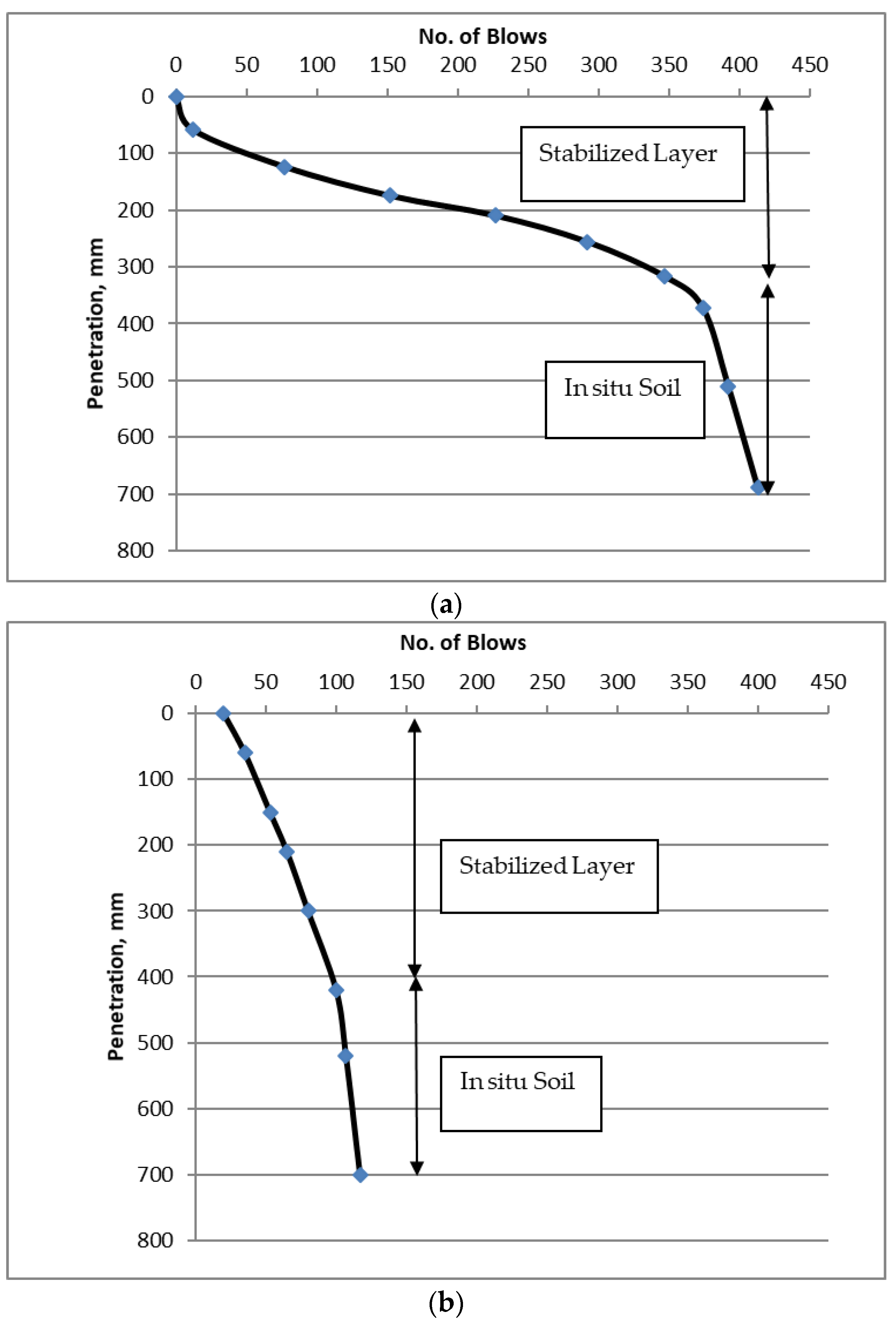
3.2. Subgrade Strength Testing Methodology

CBR is a measure that is well-recognized among highway engineers as a reasonable indicator of subgrade strength. However, since it is not convenient to measure CBR in the field, the prediction of in situ CBR values from DCP tests is considered as an acceptable alternative. This was the methodology employed in our field investigation. During the DCP test, a rod with a cone at the end was driven into the subgrade by repeatedly striking the rod with a 17.6 lb (8 kg) mass dropped from 2.26 ft (0.7 m) [19]. A graph of penetration depth vs. the cumulative number of blows was then depicted using the collected data to interpret the test results. A typical curve produced by a DCP test conducted in a CKD-stabilized subgrade as well as LKD-stabilized subgrade is shown in Figure 1. Since the stabilized subgrade was relatively stronger and harder to penetrate compared to the unstabilized in situ subgrade, the characteristic shape of the DCP plot had a straight portion with a shallow gradient, followed by a second straight portion with a much steeper gradient. Therefore, the depth that corresponds to the intersection of the two straight lines in the plot represents the bottom of the stabilized subgrade layer. Thus, the depth to the intersection of the two slopes also represents the thickness of the stabilized subgrade, if the test was started at the top of the stabilized subgrade.
Simultaneously, the same DCP plot was used to estimate the in situ CBR of the stabilized as well as the in situ subgrade. The following correlations presented in Equations (1) and (2) were used to make these estimates [19,20]:
Low plasticity clay (CL) with CBR < 10
CBR = 1 ( 0.017019 DCP ) 2
For other soils,
CBR = 292 DCP 1.12
The term DCP that appears in the above equation is the gradient of the straight portion of the DCP plot in terms of mm/blow; meanwhile, the in situ CBR calculated using the shallower gradient represents the strength of the stabilized layer; the value resulting from the steeper gradient indicates the strength of the unstabilized in situ subgrade.
All of the DCP tests were commenced at the top of the stabilized subgrade at each test location a. To reach the top surface of the stabilized subgrade, first, a 4-inch diameter (102 mm) pavement core was removed from the pavement. Then, the underlying aggregate base layer was removed using a hand auger. After the pavement was cored and hand auguring was completed, DCP tests were performed from the top surface of the stabilized layer to a depth of at least two feet below the stabilized layer. It was conducted in this way to allow for the DCP test to completely cover the in situ subgrade. During a few tests, the DCP rod was not able to advance beyond the stabilized layer, possibly due to the presence of extremely hard material. The test was terminated after a few drops, in such instances.

4. Discussion of DCP Test Results

4.1. I-75/I-96 Interchange, Wayne County, Michigan

Completed in 2008, I-75/I-96 in Wayne County, Michigan, was a reconstruction project in which a new Portland cement concrete (PCC) pavement was constructed. The mainline pavement of I-75 consisted of 13 inches (330 mm) of PCC, and the same for I-96 had 12.5 inches (317 mm) of PCC over an aggregate base of 16 inches (406 mm) in both. Due to extremely weak soil conditions, the subgrade was lime-stabilized in this project. However, two test sections of the subgrade were CKD-stabilized to compare the performance between the two stabilization methods. This project site was divided into five areas, and Area-1 and Area-2 were stabilized with CKD. The subgrade in Area-1 was mostly clay, while the subgrade in Area-2 was sand. The expected depth of stabilization for both Area-1 and Area-2 was 12 inches, according to the construction documents.
During the field-testing program for the research project that took place in September, 2014, CKD-stabilized Areas 1 and 2 were investigated to evaluate the strength of the stabilized subgrade. A picture that portrays the general site where the field tests were performed is shown in Figure 2. At the time of this field evaluation, six years had elapsed since the subgrade stabilization, but there were no visible signs of pavement distress. As per the National Oceanic and Atmospheric Administration (NOAA) online climate data, on average, the Detroit area experiences approximately five freeze–thaw (F–T) cycles per year [21]. Therefore, this stabilized subgrade must have endured about 30 F–T cycles by the time it was tested in 2014. However, the actual number of F–T cycles endured by the stabilized layer may have been lower due to actual frost depth in the area. In addition, during the time these pavement sections were in service, the average high temperature was 82 F (27.8 C), and the average low temperature was 17 F (−8.3 C) [21]. The average annual rainfall during the same period was 36.4 inches (925 mm) [21].
In each test area, the DCP tests were conducted on the outside shoulder. To reach the top of the stabilized subgrade, the PCC pavement was removed by coring, and the base material was removed by hand augering. Then, the DCP test was initiated at the top of the stabilized subgrade. The in situ CBR values and the stabilization thicknesses estimated from the DCP test results are shown in Table 2. The “N/A” note in the in situ column for test hole number 6 here refers to an instance when the DCP could not advance beyond the stabilized depth due to an unidentified obstruction. It was noticed that at Test Hole 5 (Area-2), the in situ subgrade had an in situ CBR value that was greater than the in situ CBR of the stabilized subgrade. This was probably also due to an obstruction for the DCP rod during advancing.
Based on a construction report published by the MDOT that documented the 2008 subgrade stabilization process [5], it was possible to compare the in situ CBR values reported for the stabilized subgrade in 2008 with those obtained during the field evaluation performed in 2015. The DCP tests conducted after construction in 2008 showed the in situ CBR increasing to 16.8 (stabilized soil) compared to the in situ CBR of 1.7 for the subgrade immediately below the stabilized subgrade in test Area-1, while in test Area-2, the in situ CBR increased to 25.8 (stabilized soil) from 3.3 (in situ soil). These values indicated a substantial short-term strength gain for the subgrade in 2008, due to stabilization. On average, the CKD-stabilized areas showed an 885% increase in in situ CBR when compared to the untreated subgrade.
  • The data obtained in 2014 showed that the in situ CBR of both the stabilized subgrade and unstabilized subgrade increased from the in situ CBR values that were noted in 2008. The following in situ CBR values were noted from the 2015 testing:
  • Area-1: The stabilized subgrade had an in situ CBR of 46.7 compared to the in situ CBR of 23.3 for the unstabilized subgrade.
  • Area-2: The stabilized subgrade in Area-2 had an in situ CBR of 73.2 compared to the in situ CBR of 21.1 for the unstabilized subgrade.
The DCP tests from 2008 were conducted within 3–5 days of stabilization work. While the stabilized layer had the opportunity to increase in strength, even within a few days, the unstabilized soil remained in a wet and soft condition. Since the pavement section had underdrains, the underlying unstabilized soils may not have been subjected to much moisture once the pavement was constructed in 2008. Therefore, this overall increase in the in situ CBR of the unstabilized layer may have been made possible by the lower moisture conditions, as described above. In addition, compaction during the construction of the remaining pavement layers may also have contributed to these findings. The increase in in situ CBR of the stabilized layer was due to the continued reaction of CKD, and the additional compaction received during the construction of the remaining pavement layers.
These values showed that 6 years after construction, the stabilized subgrade was still 20 to 100% stronger than the natural soil immediately below.

4.2. Waverly Road, Ingham County, Michigan

The pavement on Waverly Road was constructed in 2010, and CKD was used to stabilize a section of the subgrade, which had weak clay. The pavement section consisted of 3–4 inches (76–101 mm) of HMA, 5 inches (127 mm) of an asphalt-stabilized base, 6 inches (152 mm) of aggregate base, 9 inches (229 mm) of subbase, and 12 inches (305 mm) of CKD-stabilized subgrade. The subgrade was stabilized using a CKD application rate of 5% by weight.
The section selected for subgrade improvement consisted of two lanes in each travel direction and the center turning lane. The DCP testing was performed along the northbound and southbound travel lanes. Figure 3 presents a general view of the Waverly Road test site. When DCP tests were conducted in November, 2014, Waverly Road had been in service for four years, but there were no visible signs of pavement distress. DCP testing started at depths ranging from 3.5 to 5.5 inches from the pavement surface. Although the construction documents stated that the pavement included five inches of an asphalt-stabilized base, it was not detected during coring prior to DCP testing. On average, this area in Michigan experiences approximately 5.75 F–T cycles per year, leading us to believe that the pavement section may have endured about 23 F–T cycles between 2010 and 2014 [21]. The average high temperature for the same period was 83 F (28.3 C), and the average low temperature was 15 F (−9.4 C) [21]. The average annual rainfall for this area during the considered period was 34.8 inches (884 mm) [21].
At this site, the DCP tests commenced at the top of the base layer. The average in situ CBR of the base layer ranged from 18 to 26, with an average value of 21.5; meanwhile, the average in situ CBR of the subbase ranged from 1.1 to 41.3, with an average value of 13.5. Table 3 shows the in situ CBR values estimated from DCP test results at this site.
As seen in Table 3, only test hole 2 showed evidence of stabilization. Based on the very poor CBR values noted for the base and subbase layers, it was possible to conclude that construction deficiencies, such as poor stabilizer application uniformity and/or mixing or prolonged existence of high moisture, may have been the reason for poor and varying strengths exhibited in the base and the subbase, as well as in the stabilized subgrade in test hole numbers 1, 3, and 4. Due to these uncertainties, rather than averaging the in situ CBR values and the depth of stabilization, the values from test hole 2 were reported as results that were representative for this site.

4.3. M-84, Bay and Saginaw Counties, Michigan

The segment of M-84 included in our field testing program was constructed in 2010 on a stabilized subgrade, which was stabilized due to the poor strength of the clay subgrade. The original decision was to use lime stabilization in both the northbound and southbound lanes. However, this decision was revised during construction to use LKD stabilization instead of lime stabilization on the northbound lanes in this project between Hotchkiss Road and Salzburg Road. This was done so that the MDOT could conduct a side-by-side evaluation of the performance between lime stabilization versus LKD stabilization for this subgrade. The stabilization depth specified in the construction documents was 12 inches (305 mm).
Since the focus of this research is on CKD and LKD, in this study, our discussion is only related to the LKD-stabilized northbound test section. By the time the DCP tests were conducted in September 2014, the pavement had been in service for 4 years. As shown in Figure 4, which presents a general view of the test site, no visible pavement distress was present after four years of use. On average, this area experienced approximately 6.5 F–T cycles per year, which made the total number of F–T cycles that this stabilized subgrade may have withstood until testing to be 26 [21]. The average high temperature for the area was 82 F (27.8 C), and the average low temperature was 15 F (−9.4 C) [21]. The average annual rainfall during the period considered was 33.7 inches (856 mm) [21].
This pavement section consisted of 7.75 inches of HMA pavement underlain with 6 inches (152 mm) of aggregate base and 18 inches (457 mm) of sand subbase, as per the construction documents. Coring for the DCP tests was conducted on the paved shoulder between the white edge stripe and the concrete gutter. The DCP tests were commenced at the top of the stabilized subgrade. Table 4 shows the in situ CBR values estimated from DCP test results from this site.

4.4. SR310/US40, Licking County, Ohio

This two-lane road, which is 36 feet (11 m) wide with a center turning lane, was constructed in 2008. The shoulders are 6 feet (1.8 m) wide. According to the pre-construction borings records from this site, the existing subgrade generally consisted of sandy silts and silty clays. The pavement section consisted of a 9.25-inch (235 mm)-thick HMA surface (1.5-inch HMA surface course, 1.75-inch HMA intermediate course, a 6-inch HMA base, and 14 inches (356 mm) of LKD-stabilized subgrade. In the test area, 8% LKD stabilization was utilized. A general view of the test site is presented in Figure 5. The field tests were conducted in October, 2014, at which time the pavement had been in service for 6 years. A few longitudinal cracks were observed on the pavement at the time of field testing. Licking County area experiences approximately 4.8 F–T cycles per year, leading us to assume that the stabilized section may have undergone about 29 F–T cycles [21]. The average high and low temperatures for the area were 85 F (29.4 C) and 20 F (−6.7 C), respectively [21]. The average annual rainfall for the period considered was 41.3 inches (1049 mm) [21].
DCP testing was performed on the unpaved shoulder, 6 to 12 inches (152–305 mm) from the edge of the paved shoulder. The construction plans showed that subgrade stabilization continued for 18 inches (457 mm) beyond the edge of the paved shoulder. The unpaved shoulder was a compacted subgrade to a depth of 9.25 inches (235 mm), followed by 14 inches (356 mm) of LKD-stabilized subgrade. DCP tests were conducted at four locations on the shoulder, as shown in Table 5.

4.5. General Discussion of Results from Field Tests

A summary of the results from all four test sites is presented in Table 6. Since the results from each site have already been discussed individually, this discussion is aimed at assessing the general quality of CKD and LKD stabilization at the sites. In Table 6, the two test areas at the I-75/I-96 interchange site are presented as separate test sites for ease of discussion.
The pavements in all of the test sites had been in service for 4–6 years at the time when field testing was performed, indicating that they underwent several freeze–thaw cycles of subgrade (about three cycles per year). An important point noted in Table 6 is that in all cases, even after going through a few freeze–thaw cycles, the stabilized soils still exhibited better strength compared to the respective in situ soils. This increase was as high as 515% in CKD-stabilized soils, and 257% in LKD-stabilized soils. In fact, all three of the CKD-stabilized field test sections still had a more than 200% increase in subgrade strength. Therefore, the strength gains observed in the field (based on in situ CBR increase) in CKD-stabilized clayey soils after several freeze–thaw cycles can be considered as field verification that it is a long-term stabilization method that can be chosen with confidence.
The above findings are in line with what has been reported in Bandara et al. [8], based on laboratory testing on CKD- and LKD-stabilized soils from southeastern Michigan. As part of their findings, Bandara et al. [8] recommended that CKD should be used for the long-term stabilization of clayey soils; LKD, on the other hand, was only recommended as a stabilizer for short-term modifications of clayey soils. One reason for this not so impressive performance of LKD is the unreliability in its composition. The percentage of free lime in LKD can vary based on its source. While highly reactive LKD can have free lime contents as high as 30–40%, less reactive LKD, such as the material obtained from a dolomite lime-burning facility, may have far less free lime content. This unreliability in its composition was usually reflected in the high variability in strength gains, and this may be the reason for the lowest strength gain shown by the LKD-stabilized M-84 test section.
The depth of treatment is another aspect that is important, not only in quality control aspects, but also for billing/payments. Although the construction specifications clearly outline the required depth of treatment application, it is not clear if this depth is always verified in practice after construction. The ability to support this verification is another important aspect of DCP testing. The actual depth of stabilization found through DCP testing was compared against the expected treatment depths in Table 6. In the case of Waverly Road, the actual treatment was 88% of the expected treatment depth, and in the case of the I-75/I-96 site, it was about 96%. In the other cases, the treated depth exceeded the expected treatment depth by 100–111%. Therefore, post-construction DCP testing is not only effective in finding increases in soil strength, but also in verifying the actual depth of treatment.
Another important observation was in the optimum CKD content to be used. Based on multiple tests conducted on two different clayey soil types from Michigan, the laboratory investigation part of this investigation concluded that 4–8% was the optimum CKD content for use in clayey soils [8]. The field site I-75/I-96 showed excellent results, while Waverly Road indicated good results to a certain extent. In the case of I-75/I-96, 8% of CKD was applied and the CKD at the Waverly Road site was 5%; both were clearly within the optimum range observed in the laboratory tests.

5. Conclusions

The main findings from this research are summarized below.
CKD stabilization is a method that can improve subgrade strength, and can be used as an appropriate long-term stabilization technique for the typical clayey soils found in southeastern Michigan.
Even after 5–7 years of freeze–thaw cycles, field testing indicated the CKD-stabilized soils had at least a 200% strength gain compared to in situ soils.
Field testing indicated that LKD-stabilized soils also showed a 149–257% strength gain compared to in situ soils. As per the laboratory testing portion of this investigation elaborated in Bandara et al. [8], LKD is best suited as a soil modifier for construction purposes, rather than as a stabilizer for the long-term improvement of subgrade strength.
Post-construction DCP testing can be an effective tool, not only for assessing subgrade strength gains, but also for verifying the depth of soil stabilization.

Author Contributions

Conceptualization, N.B. and H.H.; methodology, N.B. and H.H.; formal analysis, N.B. and T.H.B.; investigation, N.B., E.J., R.P. and T.H.B.; resources, N.B.; data curation, N.B., E.J. and T.H.B.; writing—original draft preparation, H.H. and N.B.; writing—review and editing, H.H., N.B., R.P., T.H.B. and E.J.; project administration, N.B.; funding acquisition, N.B. and H.H. All authors have read and agreed to the published version of the manuscript.

Funding

This research was funded by the Michigan Department of Transportation, Contract No. 2013-0065, MDOT Research Project No. OR14-009.

Institutional Review Board Statement

Not applicable.

Informed Consent Statement

Not applicable.

Data Availability Statement

Publicly available datasets were analyzed in this study. This data can be found here: [https://mdotjboss.state.mi.us/SpecProv/getDocumentById.htm?docGuid=bcb5a90f-bb5a-45ae-9b4b-063bf69d5a53] accessed on 1 December 2022.

Conflicts of Interest

The authors declare no conflict of interest.

References

  1. MDOT. Transportation Asset Management Plan; Michigan Department of Transportation: Lansing, MI, USA, 2022.
  2. Soil Association Map of Michigan. Available online: https://esdac.jrc.ec.europa.eu/images/Eudasm/US/us59.jpg1981 (accessed on 1 December 2022).
  3. NCHRP. Characterization of Cementitiously Stabilized Layers for Use in Pavement Design and Analysis; National Corporative Highway Research Program; Transportation Research Board: Washington, DC, USA, 2014. [Google Scholar]
  4. NLA. Lime Treated Soils Saves Time and Money, National Lime Association. 2005. Available online: https://www.lime.org/documents/publications/free_downloads/tech-digest-lts.pdf (accessed on 1 January 2023).
  5. Bandara, N.; Grazioli, M. Cement Kiln Dust Stabilized Test Section on I-96/I-75 in Wayne County, Construction Report; Report No. R-1530; Michigan Department of Transportation: Lansing, MI, USA, 2009.
  6. Barman, D.; Dash, S.K. Stabilization of expansive soils using chemical additives: A review. J. Rock Mech. Geotech. Eng. 2022, 14, 1319–1342. [Google Scholar] [CrossRef]
  7. National Cooperative Highway Research Program (NCHRP). Synthesis 435: Recycled Materials and Byproducts in Highway Applications Manufacturing and Construction Byproducts; The National Academies Press: Washington, DC, USA, 2013. [Google Scholar] [CrossRef]
  8. Bandara, N.; Hettiarachchi, H.; Jensen, E.; Binoy, T.H. Upcycling Potential of Industrial Waste in Soil Stabilization: Use of Kiln Dust and Fly Ash to Improve Weak Pavement Subgrades Encountered in Michigan, USA. Sustainability 2020, 12, 7226. [Google Scholar] [CrossRef]
  9. Portland Cement Association (PCA). Soil-Cement Laboratory Handbook; Portland Cement Association (PCA): Skokie, IL, USA, 1992. [Google Scholar]
  10. United States Environmental Protection Agency (USEPA). Regulatory Determination on Cement Kiln Dust: 40 CFR Part 261; Environmental Protection Agency, Federal Register: Washington, DC, USA, 1995.
  11. Little, D.N. Evaluation of Structural Properties of Lime Stabilized Soils and Aggregates; The National Lime Association: Arlington, VA, USA, 2008; Available online: https://www.lime.org/documents/publications/free_downloads/soils-aggregates-vol1.pdf (accessed on 1 December 2022).
  12. Sargand, I.K.; Gray, J.; Al-Jhayyish, A. Incorporating Subgrade Stabilization in Pavement Design and Construction; Report FHWA/OH-2014/12; Ohio Department of Transportation: Columbus, OH, USA, 2014.
  13. Little, D.N.; Nair, S. Recommended Practice for Stabilization of Subgrade Soils and Base Materials; NCHRP W144; Transportation Research Board: Washington, DC, USA, 2009. [Google Scholar]
  14. Little, D.N.; Nair, S. Recommended Practice for Stabilization of Sulfate Rich Subgrade Soils; NCHRP W145; Transportation Research Board: Washington, DC, USA, 2009. [Google Scholar]
  15. Miller, G.A.; Zaman, M. Field and Laboratory Evaluation of Cement Kiln Dust as a Soil Stabilizer; Transportation Research Record No. 1714; Transportation Research Board: Washington, DC, USA, 2000; pp. 25–32. [Google Scholar]
  16. Jung, C.; Bobet, A. Post-Construction Evaluation of Lime-Treated Soils; Report FHWA/IN/JTRP-2007/25; Indiana Department of Transportation: Indianapolis, IN, USA, 2008.
  17. Li, X.; Wang, J.; Muhunthan, B. Field Calibration of Fatigue Models of Cementitiously Stabilized Pavement Materials for Use in the Mechanistic-Empirical Pavement Design Guide. Transp. Res. Rec. J. Transp. Res. Board 2019, 2673, 427–435. [Google Scholar] [CrossRef]
  18. Rothhamel, M.; Al-Jabban, W.J.; Laue, J. Influence factors for using hydraulic binders for soils stabilization of fine-grained soils in cold environment. IOP Conf. Ser. Earth Environ. Sci. 2021, 710, 012050. [Google Scholar] [CrossRef]
  19. ASTM D 6951; Standard Test Method for Use of the Dynamic Cone Penetrometer in Shallow Pavement Applications. ASTM International: West Conshohocken, PA, USA, 2018. Available online: https://www.astm.org/d6951_d6951m-18.html (accessed on 1 December 2022).
  20. USACE. Description and Application of Dual Mass Dynamic; United States Army Corps of Engineers: Washington, DC, USA, 1992.
  21. National Oceanic and Atmospheric Administration (NOAA). Online Climate Data; National Centers for Environmental Information, Department of Commerce: Washington DC, USA, 2023. Available online: https://www.ncei.noaa.gov/cdo-web/ (accessed on 1 January 2023).
Figure 1. Sample DCP results plots: (a) CKD-stabilized subgrade from the I-75/I-96 interchange site, and (b) LKD-stabilized subgrade from the M-84 site.
Geotechnics 03 00011 g001
Figure 2. General site overview showing no visible pavement distresses, I-75/I-96 interchange, Wayne County, Michigan.
Geotechnics 03 00011 g002
Figure 3. General site overview showing no visible pavement distresses, Waverly Road, Ingham County, Michigan.
Geotechnics 03 00011 g003
Figure 4. General site overview showing no visible pavement distresses, M-84, Bay and Saginaw Counties, Michigan.
Geotechnics 03 00011 g004
Figure 5. General site overview only showing a few longitudinal cracks, SR310/US40, Licking County, Ohio.
Geotechnics 03 00011 g005
Table 1. Stabilized subgrade sections selected for field data collection.
Site (Constructed by) Stabilizer (% Application)Construction Year
I-75/I-96 Interchange, Wayne County, Michigan (Project owner: Michigan DOT)CKD (8%)2008
Waverly Road, Ingham County, Michigan (Project Owner: Ingham County, Michigan)CKD (5%)2010
M-84, Bay and Saginaw Counties, Michigan (Project Owner: Michigan DOT)LKD (6%)2010
SR310/US40, Licking County, Ohio (Project Owner: Ohio DOT)LKD (8%)2008
Table 2. Results for the I-75/I-96 interchange test sections, Wayne County, Michigan.
Test Hole NumberIn Situ CBR (%)Stabilized Depth in Inches (mm)Average In Situ CBR (%)Average Stabilized Depth in Inches (mm)
Stabilized SubgradeIn Situ SubgradeStabilized SubgradeIn Situ Subgrade
1 (Area-1)39.032.811.4 (290)46.723.311.4 (290)
2 (Area-1)5.07.09.8 (249)
3 (Area-1)96.130.013.1 (333)
4 (Area-2)73.221.112.0 (305)73.221.112.0 (305)
5 (Area-2)75.7100.0 *12.0 (305)
6 (Area-2)56.3N/A *13.5 (343)
* Note: the results from test holes # 5 and 6 were excluded when averaging the results.
Table 3. Results for the Waverly Road test section, Ingham County, Michigan.
Test Hole NumberIn Situ CBR (%)Stabilized Depth in Inches (mm)In Situ Average CBR (%)Average Stabilized Depth in Inches (mm)
Stabilized SubgradeIn Situ SubgradeStabilized SubgradeIn Situ Subgrade
13.245.410.8 (274)87.5 *17.0 *10.5 (267)
287.517.011.4 (290)
31.72.510.8 (274)
412.728.99.1 (231)
* Note: the results from test hole #2 were reported as valid results, due to the inconsistencies observed in the other results.
Table 4. Results for the M-84 test section, Bay and Saginaw Counties, Michigan.
Test Hole Number In Situ CBR (%)Stabilized Depth in Inches (mm)Average In Situ CBR (%)Average Stabilized Depth in Inches (mm)
Stabilized SubgradeIn Situ SubgradeStabilized SubgradeIn Situ Subgrade
129.69.317.7 (442)23.215.613.3 (592)
221.116.013.6 (345)
318.921.58.7 (221)
528.456.216.5 (144)
639.816.820.5 (521)
Table 5. Results for the SR310/US40 test section, Licking County, Ohio.
Test Hole NumberIn Situ CBR (%)Stabilized Layer Thickness in Inches (mm)Average In Situ CBR (%)Average Stabilized Depth in Inches (mm)
Stabilized SubgradeIn Situ SubgradeStabilized SubgradeIn Situ Subgrade
TH150.19.916.6 (422)49.819.4
TH280.223.716.9 (429)
TH373.031.79.7 (246)14.5
TH461.812.315.0 (381)
Table 6. Summary of field test results and climatic data.
Test SiteStabilizer (In Situ Soil Condition)Year Built (Age in Years at the Time of Field Testing)Expected Treatment Thickness in Inches (mm)Thickness per 2015 Tests in Inches (mm)% Gain in In Situ CBR (Stabilized/Unstabilizedx100)Average High/Low Temperature in F (C)
[21]
Average Annual Precipitation in Inches (mm)
[21]
I-75/I-96 Area-1CKD 8%
(Clay Subgrade)
2008 (6)12 (305)11.4 (290)20082/17 (27.8/−8.3)36.4 (925)
I-75/I-96 Area-2CKD 8%
(Sand Subgrade)
2008 (6)12 (305)12.0 (305)34782/17 (27.8/−8.3)36.4 (925)
Waverly RoadCKD 5%
(Clay Subgrade)
2010 (4)12 (305)10.5 (267)51583/15 (28.3/−9.4)34.8 (884)
M-84 NBLKD 6%
(Clay Subgrade)
2010 (4)12 (305)13.3 (338)14982/15 (27.8/−9.4)33.7 (856)
SR310/
US40
LKD 8%
(Sandy Silt and Silty Clay)
2008 (6)14 (356)14.5 (368)25785/20 (29.4/−6.7)41.3 (1049)
Disclaimer/Publisher’s Note: The statements, opinions and data contained in all publications are solely those of the individual author(s) and contributor(s) and not of MDPI and/or the editor(s). MDPI and/or the editor(s) disclaim responsibility for any injury to people or property resulting from any ideas, methods, instructions or products referred to in the content.

