


Microstructure and Strength Parameters of Cement-Stabilized Loess


Abstract
:
1. Introduction
2. Materials and Methods
2.1. Raw Materials
2.2. Specimen Preparation
2.3. Testing Methods
2.3.1. Flexural Strength Test
2.3.2. Unconfined Compression Test
2.3.3. Compaction Test
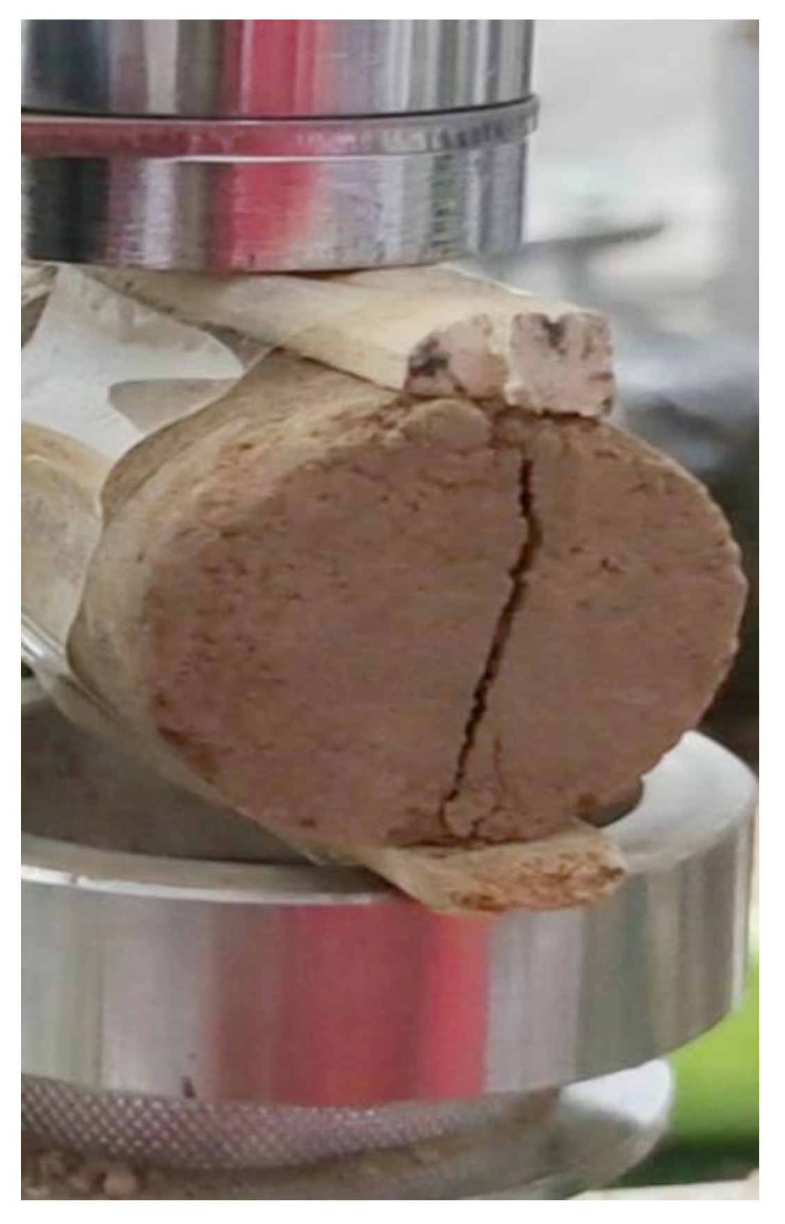
2.3.4. Indirect Tensile Strength
2.3.5. Direct Shear Test
2.3.6. Water Absorption Test
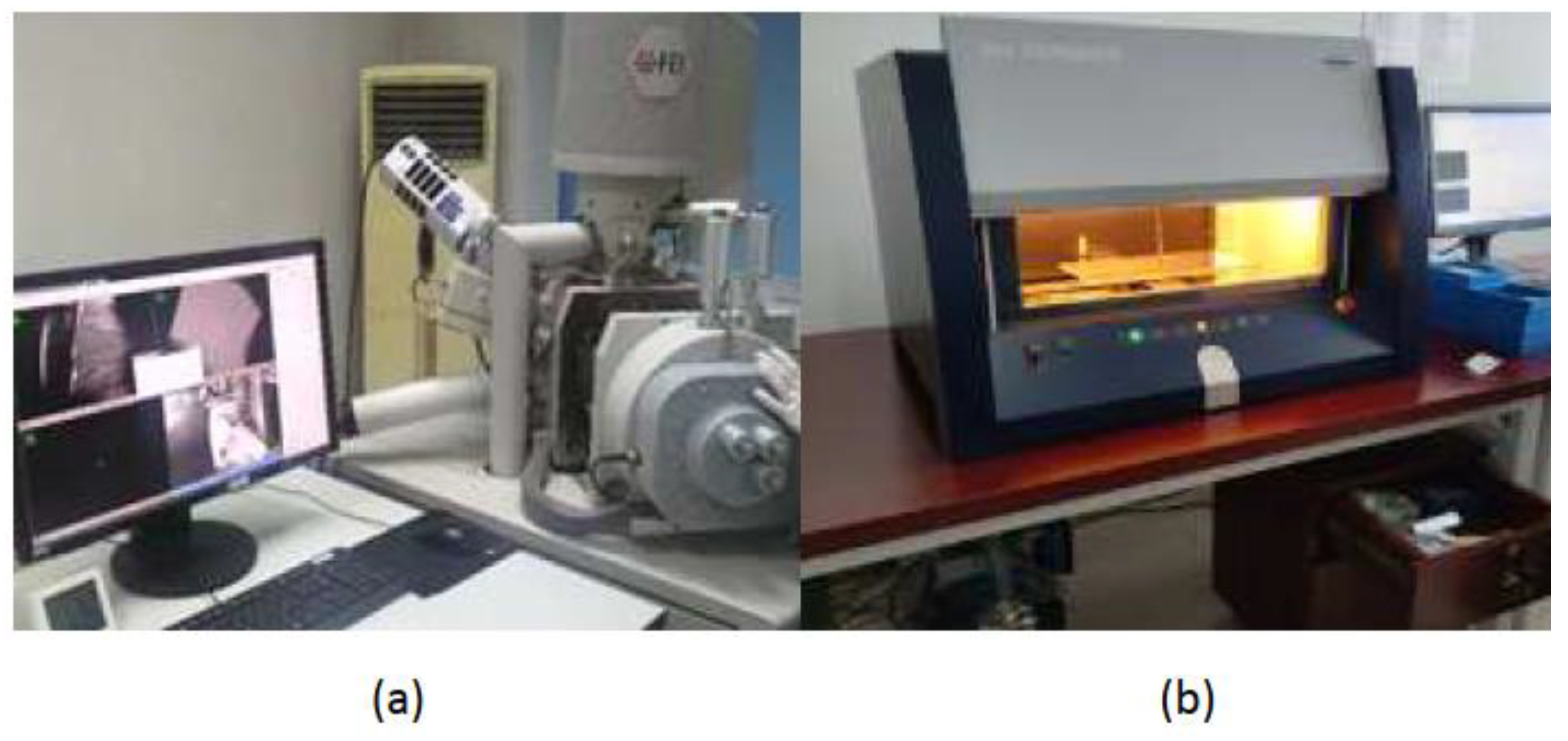
2.3.7. Microstructural Analysis
3. Results and Discussion
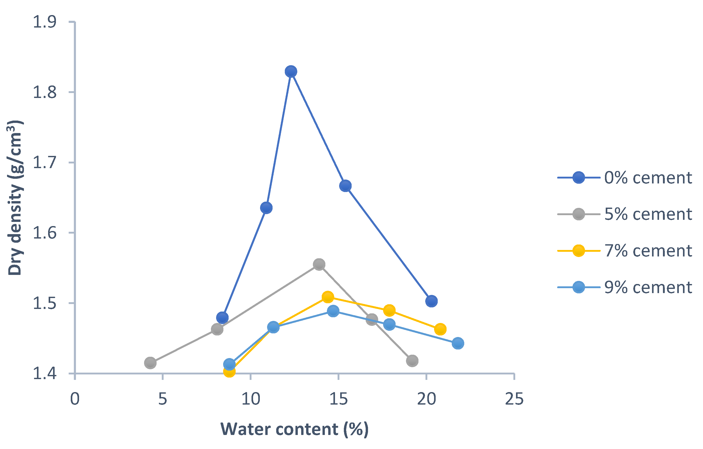
3.1. Compaction Properties
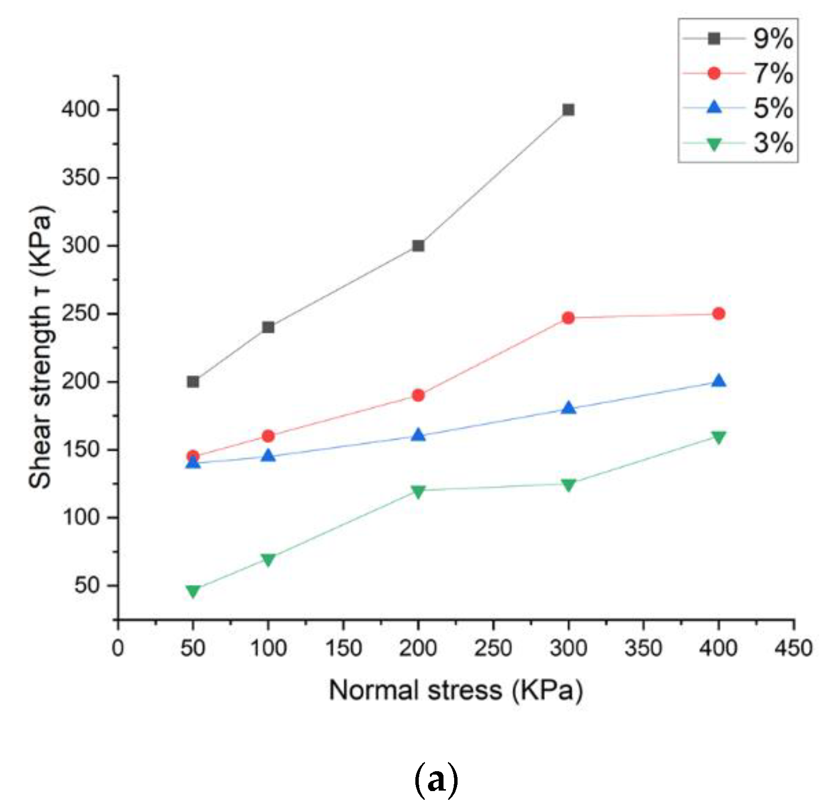
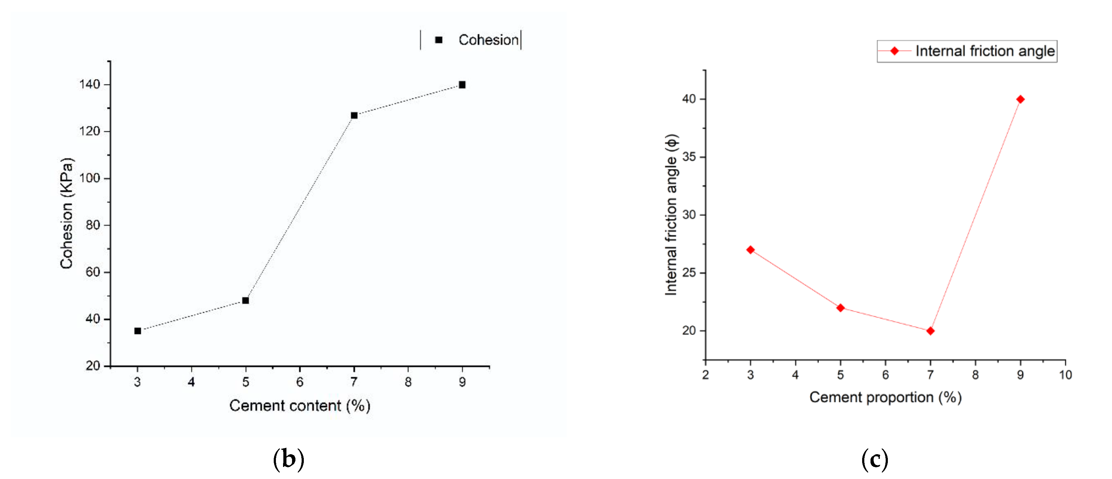
3.2. Shear Strength
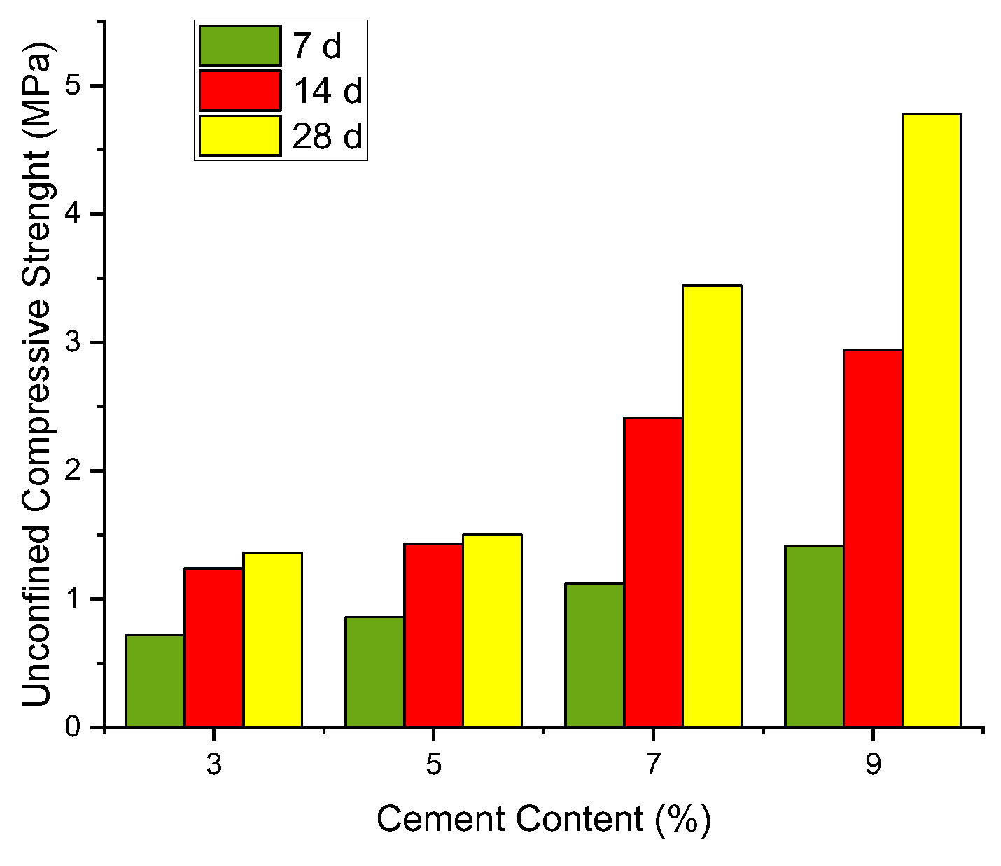
3.3. Unconfined Compressive Test
3.4. Flexural Strength
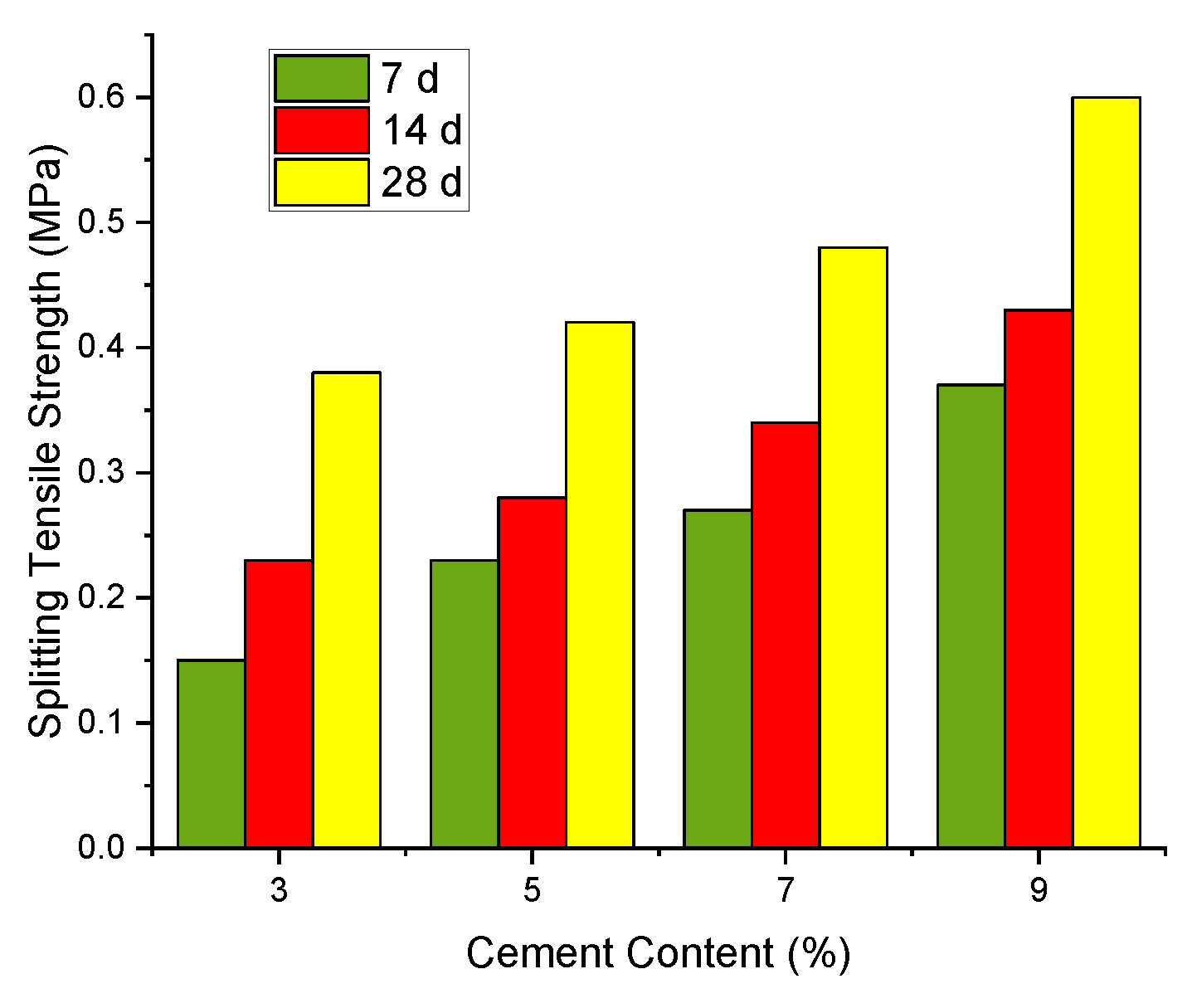
3.5. Splitting Tensile Strength Test
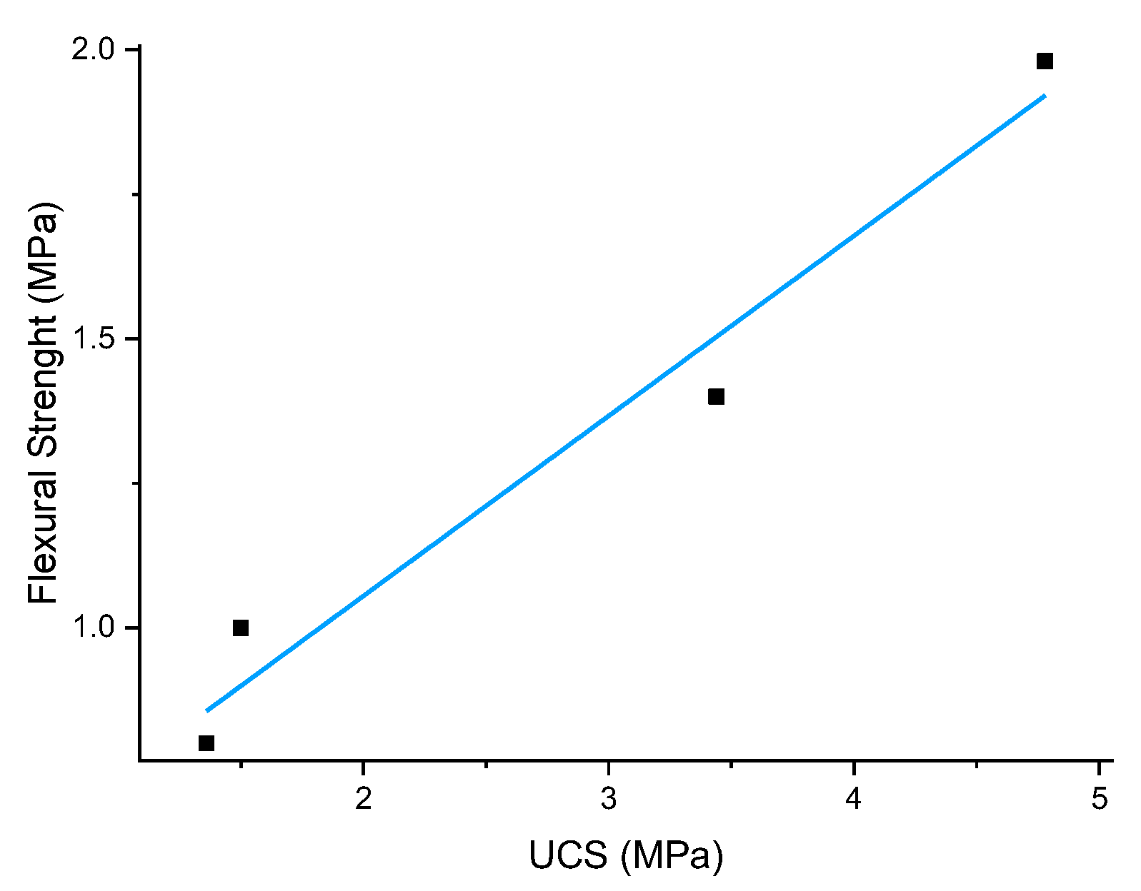
3.6. Flexural–Compressive Strength Relationship
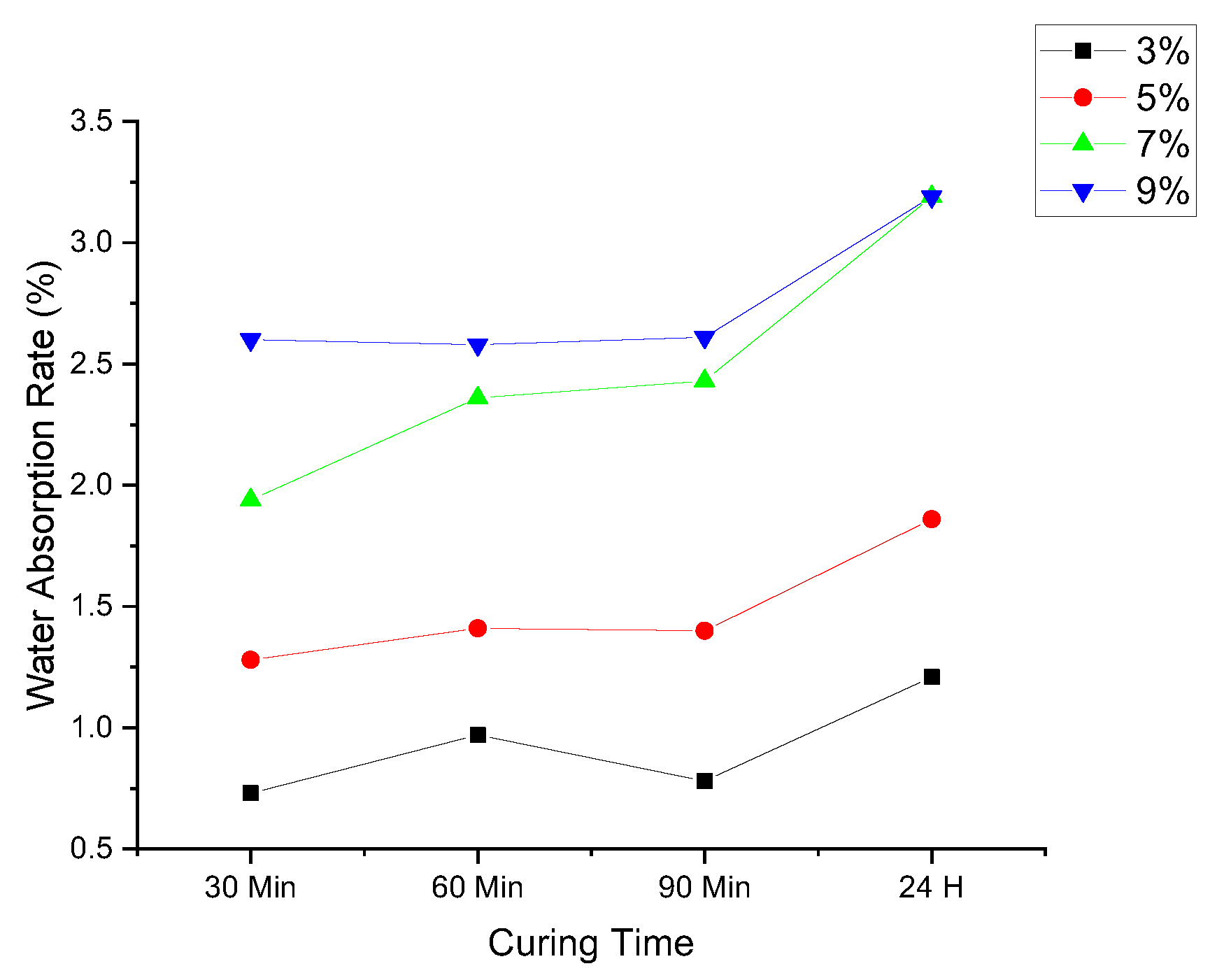
3.7. Water Resistance
3.8. Microstructure Analysis
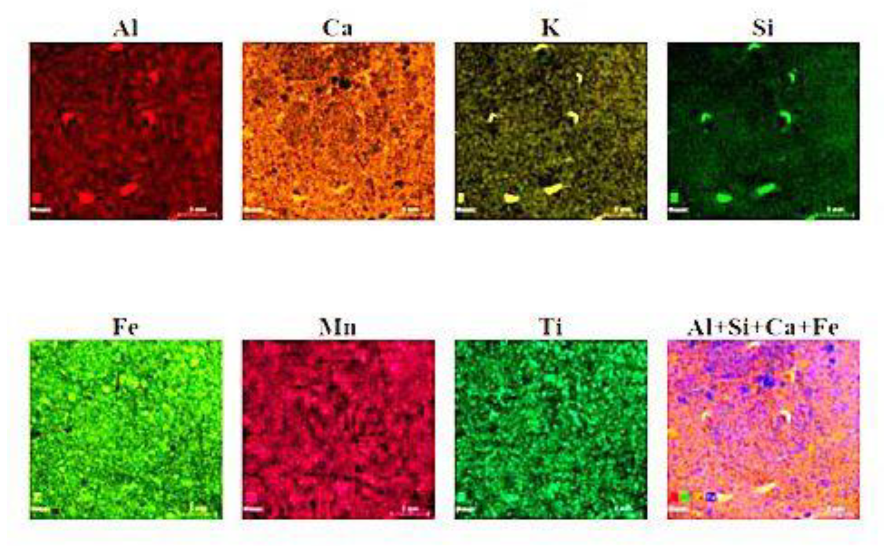
3.8.1. XRF Analyses
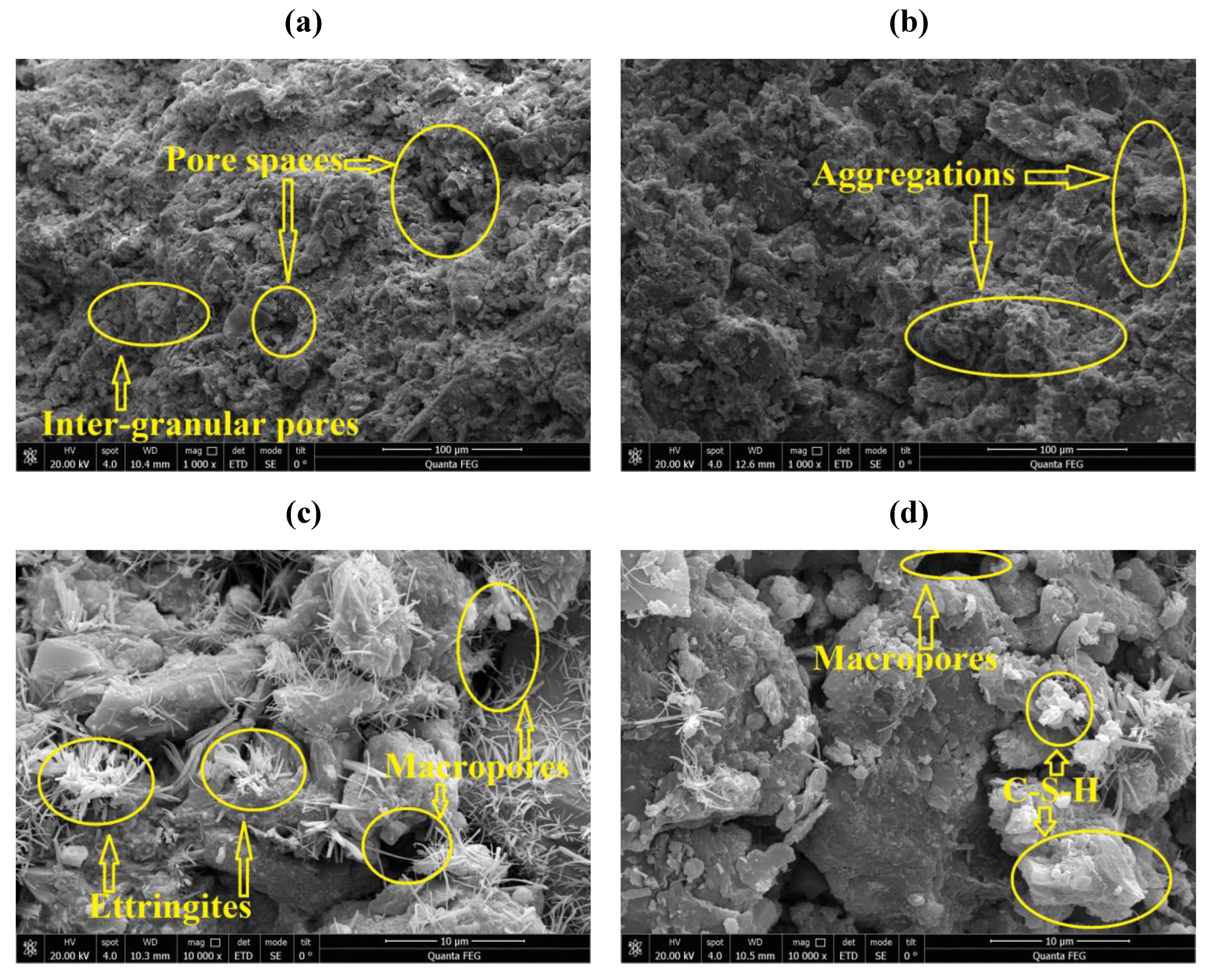
3.8.2. SEM Analyses
4. Conclusions
- (1)
- Cement minimises loess flexibility. Increasing shear strength correlated with changes in cohesiveness. This study shows that cohesiveness in cement-stabilized loess is more structure-sensitive than friction angle and that bonding is necessary for shear strength gain following remoulding.
- (2)
- The compressive strength increases without limit as the cement amount and curing time increase. The unconfined compressive strength of a given cement content increases as curing time increases.
- (3)
- With more cement added and the ideal moisture level decreased, the maximum dry density increases.
- (4)
- Tensile and bending strengths grow with the quantity of cement used and the curing period.
- (5)
- After 28 days, the specimens’ flexural strength increased most when the cement concentration was between 7% and 9%.
- (6)
- Cement pozzolanic reaction enhanced the strength properties of the loess by creating ettringite and C-S-H gels.
Author Contributions
Funding
Institutional Review Board Statement
Informed Consent Statement
Data Availability Statement
Acknowledgments
Conflicts of Interest
References
- Peng, D.; Xu, Q.; Qi, X.; Fan, X.; Dong, X.; Li, S.; Ju, Y. Study on early recognition of loess landslides based on field investigation. Int. J. Georesources Environ. 2016, 2, 35–52. [Google Scholar] [CrossRef]
- Shi, Y.-C.; Lin, X.-W.; Wang, L.-M. Earthquake damage characteristics of raw soil buildings in loess areas and disaster prevention countermeasures. J. Nat. Disasters 2003, 12, 87–92. [Google Scholar]
- Pei, X.; Zhang, F.; Wu, W.; Liang, S. Physicochemical and index properties of loess stabilized with lime and fly ash piles. Appl. Clay Sci. 2015, 114, 77–84. [Google Scholar] [CrossRef]
- Derbyshire, E. Geological hazards in loess terrain, with particular reference to the loess regions of China. Earth-Sci. Rev. 2001, 54, 231–260. [Google Scholar] [CrossRef]
- Yongshuang, Z.; Yongxin, Q.U. Cements of sand loess and their cementation in north Shaanxi and west Shanxi. Geol. Eng. J. 2005, 13, 18–28. [Google Scholar]
- Leng, Y.; Peng, J.; Wang, Q.; Meng, Z.; Huang, W. A fluidized landslide occurred in the Loess Plateau: A study on loess landslide in South Jingyang tableland. Eng. Geol. 2018, 236, 129–136. [Google Scholar] [CrossRef]
- Jefferson, I.; Rogers, C.; Evstatiev, D.; Karastanev, D. Treatment of metastable loess soils: Lessons from Eastern Europe. In Elsevier Geo-Engineering Book Series; Elsevier: Amsterdam, The Netherlands, 2005; Volume 3, pp. 723–762. ISBN 1571-9960. [Google Scholar]
- Romero, E. A microstructural insight into compacted clayey soils and their hydraulic properties. Eng. Geol. 2013, 165, 3–19. [Google Scholar] [CrossRef]
- Qiu, H.J.; Cui, P.; Hu, S.; Liu, Q.; Wang, Y.; Gao, Y.; Deng, M. Size-frequency distribution of landslides in different landforms on the Loess Plateau of Northern Shaanxi. Earth Sci. 2016, 41, 343–350. [Google Scholar]
- Crawford, M.M.; Bryson, L.S.; Woolery, E.W.; Wang, Z. Long-term landslide monitoring using soil-water relationships and electrical data to estimate suction stress. Eng. Geol. 2019, 251, 146–157. [Google Scholar] [CrossRef]
- Jayasinghe, C.; Kamaladasa, N. Compressive strength characteristics of cement stabilized rammed earth walls. Constr. Build. Mater. 2007, 21, 1971–1976. [Google Scholar] [CrossRef]
- Wang, L.; Chen, L.; Cho, D.-W.; Tsang, D.C.; Yang, J.; Hou, D.; Baek, K.; Kua, H.W.; Poon, C.-S. Novel synergy of Si-rich minerals and reactive MgO for stabilisation/solidification of contaminated sediment. J. Hazard. Mater. 2019, 365, 695–706. [Google Scholar] [CrossRef]
- Liu, H.M.; Wang, L.M.; Gao, P. The mechanical properties of cement reinforced loess and pore microstructure characteristics. In Applied Mechanics and Materials; Trans Tech Publications: Stafa-Zurich, Switzerland, 2014; Volume 527, pp. 25–30. [Google Scholar]
- James, J.; Pandian, P.K. Industrial wastes as auxiliary additives to cement/lime stabilization of soils. Adv. Civ. Eng. 2016, 2016, 1267391. [Google Scholar] [CrossRef] [Green Version]
- A Rashid, A.S.; Bunawan, A.R.; Mat Said, K.N. The deep mixing method: Bearing capacity studies. Geotech. Geol. Eng. 2017, 35, 1271–1298. [Google Scholar] [CrossRef]
- Kaniraj, S.R.; Havanagi, V.G. Compressive strength of cement stabilized fly ash-soil mixtures. Cem. Concr. Res. 1999, 29, 673–677. [Google Scholar] [CrossRef]
- Subramanian, S.; Khan, Q.; Ku, T. Effect of sand on the stiffness characteristics of cement-stabilized clay. Constr. Build. Mater. 2020, 264, 120192. [Google Scholar] [CrossRef]
- EN 12390-5:2009; Testing Hardened Concrete—Part 5: Flexural Strength of Test Specimens. iTeh Standards: Etobicoke, ON, Canada, 2009. Available online: https://standards.iteh.ai/catalog/standards/cen/275df2f9-c466-4bb1-b41c-b8dfa9fc6d89/en-12390-5-2009 (accessed on 22 March 2023).
- GB/T 50123-1999; PDF in English. National Standards of the People’s Republic of China: Beijing, China, 1999. Available online: https://www.chinesestandard.net/PDF.aspx/GBT50123-1999 (accessed on 22 March 2023).
- EN 13286-42:2003; Unbound and Hydraulically Bound Mixtures—Part 42: Test Method for the Determination of the Indirect Tensile Strength of Hydraulically Bound Mixtures. iTeh Standards: Etobicoke, ON, Canada, 2003. Available online: https://genorma.com/en/project/show/cen:proj:10813 (accessed on 22 March 2023).
- ASTM D 3080; Standard Test Method for Direct Shear Test of Soils Under Conslidated Drained Conditions—Studocu. ASTM International: West Conshohocken, PA, USA, 1998. Available online: https://www.studocu.com/en-us/document/stony-brook-university/prestressed-concrete-design/astm-d-3080-standard-test-method-for-direct-shear-test-of-soils-under-conslidated-drained-conditions/27406807 (accessed on 22 March 2023).
- Hossain, K.M.A.; Lachemi, M.; Easa, S. Stabilized soils for construction applications incorporating natural resources of Papua New Guinea. Resour. Conserv. Recycl. 2007, 51, 711–731. [Google Scholar] [CrossRef]
- Seco, A.; Ramírez, F.; Miqueleiz, L.; García, B. Stabilization of expansive soils for use in construction. Appl. Clay Sci. 2011, 51, 348–352. [Google Scholar] [CrossRef]
- Kumar, A.; Walia, B.S.; Bajaj, A. Influence of fly ash, lime, and polyester fibers on compaction and strength properties of expansive soil. J. Mater. Civ. Eng. 2007, 19, 242–248. [Google Scholar] [CrossRef]
- Kasama, K.; Zen, K.; Iwataki, K. Undrained shear strength of cement-treated soils. Soils Found. 2006, 46, 221–232. [Google Scholar] [CrossRef] [Green Version]
- Consoli, N.C.; Foppa, D.; Festugato, L.; Heineck, K.S. Key parameters for strength control of artificially cemented soils. J. Geotech. Geoenviron. Eng. 2007, 133, 197–205. [Google Scholar] [CrossRef]
- Zhang, P.; Li, Q.; Wei, H. Investigation of flexural properties of cement-stabilized macadam reinforced with polypropylene fiber. J. Mater. Civ. Eng. 2010, 22, 1282–1287. [Google Scholar] [CrossRef]
- Consoli, N.C.; de Moraes, R.R.; Festugato, L. Parameters controlling tensile and compressive strength of fiber-reinforced cemented soil. J. Mater. Civ. Eng. 2013, 25, 1568–1573. [Google Scholar] [CrossRef]
- SNI 7064:2014; Semen Portland Komposit | Perpustakaan Khazanah Analitika. Badan Standar Nasional: Jakarta, Indonesia, 2014. Available online: http://pustaka.smakbo.sch.id/index.php?p=show_detail&id=2501&keywords= (accessed on 22 March 2023).
- Chen, T.; Gao, X. Effect of carbonation curing regime on strength and microstructure of Portland cement paste. J. CO2 Util. 2019, 34, 74–86. [Google Scholar] [CrossRef]
- Qin, L.; Gao, X. Properties of coal gangue-Portland cement mixture with carbonation. Fuel 2019, 245, 1–12. [Google Scholar] [CrossRef]
- Angelova, R.; Evstatiev, D. Strength grain stages of soil-cement. In Proceedings of the 6th International Congress International Association of Engineering Geology, Amsterdam, The Netherlands, 6–10 August 1990; pp. 3147–3154. [Google Scholar]


| Property | Value |
|---|---|
| Gs | 2.71 |
| ρmax (g/cm3) | 1.82 |
| wopt (%) | 12.00 |
| Atterberg limits | |
| Liquid limit (%) | 31.33 |
| Plasticity index (%) | 15.00 |
| Plastic limit (%) | 18.33 |
| Particle size distribution | |
| Sand, 0.05–2.0 mm | 19.43% |
| Silt, 0.002–0.05 mm | 73.98% |
| Clay, <0.002 mm | 7.59% |
| Chemical Name | SiO2 | A12O3 | CaO | Fe2O3 | MgO | K2O | Na2O | TiO2 |
|---|---|---|---|---|---|---|---|---|
| % | 59.47 | 14.72 | 11.82 | 5.07 | 3.21 | 2.79 | 1.59 | 0.72 |
| USDA classification | Silt loam | |||||||
| Minerals present | Kaolinite and illite | |||||||
| Elemental Analysis | Si | Ca | A1 | Fe | K | Mg | Ti |
|---|---|---|---|---|---|---|---|
| % | 52.84 | 16.38 | 13.21 | 8.09 | 4.87 | 3.26 | 1.04 |
| SiO2 | Al2O3 | Fe2O3 | MnO2 | SO3 | CaO | Ignition Loss |
|---|---|---|---|---|---|---|
| 22.60 | 4.98 | 2.90 | 2.32 | 2.31 | 61.60 | 4.48 |
| Density/(g.cm−3) | Specific Surface Area/(m2/kg) | Setting Time/Min | Flexural Strength/MPa | Compressive Strength/MPa | |||
|---|---|---|---|---|---|---|---|
| 3.16 | 363 | Initial | Final | 3 d | 28 d | 3 d | 28 d |
| 170 | 210 | 6.3 | 9.2 | 26.8 | 49.7 | ||
| Compound | Concentration (%) | Chemical Composition | Content (%) |
|---|---|---|---|
| Al | 1.72 | Al2SO3 | 3.25 |
| O | 18.58 | ||
| Si | 6.95 | SiO2 | 14.86 |
| P | 0.00 | P2O5 | 0.00 |
| S | 0.09 | SO3 | 0.23 |
| Cl | 49.90 | ||
| K | 2.31 | K2O | 2.79 |
| Ca | 12.09 | CaO | 16.92 |
| Ti | 0.61 | TiO2 | 1.01 |
| V | 0.03 | ||
| Mn | 0.15 | MnO | 0.20 |
| Fe | 7.54 | Fe2SO3 | 10.79 |
| Zn | 0.03 | ZnO | 0.00 |
| Rh | 0.00 |
Disclaimer/Publisher’s Note: The statements, opinions and data contained in all publications are solely those of the individual author(s) and contributor(s) and not of MDPI and/or the editor(s). MDPI and/or the editor(s) disclaim responsibility for any injury to people or property resulting from any ideas, methods, instructions or products referred to in the content. |
© 2023 by the authors. Licensee MDPI, Basel, Switzerland. This article is an open access article distributed under the terms and conditions of the Creative Commons Attribution (CC BY) license (https://creativecommons.org/licenses/by/4.0/).
Share and Cite
Axel, M.; Li, X.; Wen, F.; An, M.-X. Microstructure and Strength Parameters of Cement-Stabilized Loess. Geotechnics 2023, 3, 161-178. https://doi.org/10.3390/geotechnics3020010
Axel M, Li X, Wen F, An M-X. Microstructure and Strength Parameters of Cement-Stabilized Loess. Geotechnics. 2023; 3(2):161-178. https://doi.org/10.3390/geotechnics3020010
Chicago/Turabian StyleAxel, Mani, Xi’an Li, Feng Wen, and Ming-Xiao An. 2023. "Microstructure and Strength Parameters of Cement-Stabilized Loess" Geotechnics 3, no. 2: 161-178. https://doi.org/10.3390/geotechnics3020010