
Density-Driven Convection for CO2 Solubility Trapping in Saline Aquifers: Modeling and Influencing Factors

1
Guangdong-Hong Kong-Macao Joint Laboratory for Contaminants Exposure and Health, Guangzhou Key Laboratory Environmental Catalysis and Pollution Control, Institute of Environmental Health and Pollution Control, Guangdong University of Technology, Guangzhou 510006, China
2
Guangdong Key Laboratory of Environmental Catalysis and Health Risk Control, Key Laboratory for City Cluster Environmental Safety and Green Development of the Ministry of Education, School of Environmental Science and Engineering, Guangdong University of Technology, Guangzhou 510006, China
3
School of Engineering and Materials Science, Queen Mary University of London, Mile End Road, London E1 4NS, UK
*
Authors to whom correspondence should be addressed.
Geotechnics 2023, 3(1), 70-103; https://doi.org/10.3390/geotechnics3010006
Submission received: 28 January 2023
/
Revised: 21 February 2023
/
Accepted: 1 March 2023
/
Published: 3 March 2023
(This article belongs to the Special Issue Multiscale and Multiphysics Modeling of Sub-Surface Geological Systems)
Abstract
:Industrial development has significantly increased the concentration of CO2 in the atmosphere, resulting in the greenhouse effect that harms the global climate and human health. CO2 sequestration in saline aquifers is considered to be one of the efficient ways to eliminate atmospheric CO2 levels. As an important mechanism, the solubility trapping greatly determines the efficiency of CO2 sequestration in saline aquifers, and this depends, in turn, on the density-driven convection that occurs during the sequestration. Density-driven convection is influenced by multiple factors. However, existing discussions on some of these influential factors are still ambiguous or even reach contradictory conclusions. This review summarizes the common modeling approaches and the influence of factors on density-driven convection. We suggest that saline aquifers with high values of depth, permeability, pH, and SO2 impurity concentration are the ideal CO2 sequestration sites. A certain degree of porosity, fractures, stratification, slope, hydrodynamic dispersion, background flow, and formation pressure are also considered advantageous. Meanwhile, the geological formation of the Permian White Rim Sandstone or carbonate is important, but it should not contain brine with excessive viscosity and salinity. Finally, we discuss the contents in need of further research.

1. Introduction
As the negative impacts of global warming are becoming more and more significant, the general policy on climate-change prevention is universally being recognized around the world. Based on the extent of global warming, the mid- to long-term (2041–2100) impact was predicted to be several times higher than currently observed for some of the major risks that have been identified [1,2]. Geological storage of CO2 is a promising resolution to the growing global climate and environmental issues, as it would reduce the atmospheric CO2 concentration [3,4,5]. Among the various options for CO2 sequestration, subsurface saline aquifers are considered the most feasible due to the presence of large, porous, and permeable formation in sedimentary basins worldwide, as these have the greatest potential for CO2 sequestration compared to others. Additionally, large pores with high permeability require fewer injection wells and facilitate pressure dissipation for these formations [5,6].
There are four trapping mechanisms in saline aquifers, i.e., structural trapping, capillary trapping, solubility trapping, and mineral trapping [7]. The CO2 injected into saline aquifers assumes a supercritical state under high temperature and pressure stratigraphic conditions [8]. Despite the dramatic increase in density due to the reduction in volume, supercritical CO2 is still lighter than the brine of the formation. It therefore rises under buoyancy and accumulates at the top of the saline aquifer by the barrier of the caprock, which is called structural trapping. CO2 in an irreducible gas saturation state is trapped in the pores and cannot move because of the interfacial tension between CO2 and formation, known as capillary trapping. The accumulated CO2 below the caprock gradually dissolves with time into the brine and is thus isolated from the atmosphere, known as the solubility trapping in saline aquifers. The dissolved CO2 reacts chemically with the minerals in the formation and eventually transforms into solid carbonate minerals, which are precipitated in the pore space, known as mineral trapping. Among them, solubility trapping is regarded as a more effective and secure mechanism in the medium to long term, as well as providing the necessary requirements for permanent mineral trapping [9].
In the early stages of solubility trapping, CO2 transfers to brine in the form of diffusion. The density of the brine in contact with CO2 thus increases, creating a density difference with the surrounding CO2-free brine. This determines that the CO2–brine interface is unstable. The sharp vertical concentration gradient of CO2 results in molecular diffusion being the main mass transfer mechanism, and the development of the instability is arrested. As an increase in the thickness of the diffusion boundary layer occurs, the diffusive flux decreases, instability develops, and eventually the CO2-rich brine with a large density settles downward by gravity and the surrounding lighter brine thus migrates upward, creating convection called density-driven convection. Once it occurs, it replaces molecular diffusion as the dominant form for the mass transfer of CO2 into the brine. This will greatly facilitate the flow of aquifer fluids and greatly improve the efficiency of CO2 dissolution and migration. It accelerates the transfer of CO2 into the brine and therefore facilitates the practical benefits of the long-term security of CO2 injection and storage. Studying the occurrence and form of density-driven convection is necessary to understand the role and mechanisms of solubility trapping.
Understanding subsurface flow dynamics is necessary to evaluate the effectiveness of geological storage, which in turn necessitates the comprehension of a wide range of geologic characteristics in a candidate reservoir. Several significant potential CO2 reserves showed sedimentary architecture that reflected river deposition, such as the Morrow Sandstone [10] and the lower Paaratte Formation [11], which were mainly made of conglomerate or sandstone. The spatial structure of textural facies, which were, in fact, of fundamental relevance, could be explained by depositional architecture, and those finer- and coarser-grained sedimentary textures might be a major factor influencing the variation of a petrophysical property such as permeability [12]. The sedimentary architecture could be found in both contemporary fluvial environments and historical fluvial reservoirs, and its mean particle sizes range from sand (e.g., the Mt. Simon Sandstone [13]) to gravel (e.g., the Ivishak Formation conglomerate [14]). Moreover, the sharp, abrupt boundaries between cross-sets of coarse and fine grains could lead to aquifer connectedness and possibly tortuous flow channels, which limited the movement of CO2 [15,16]. Consequently, when constructing a fundamental scientific understanding of CO2 injection and transport, it is necessary to take into account the complexity of the sedimentary structure found within such reservoirs.
Many investigations have been conducted on the density-driven convection for CO2 solubility trapping in saline aquifers [17,18]. However, the coupling of flow and mass transfer makes the convection process highly nonlinear, resulting in complex hydrodynamic behavior and CO2 distribution. The modeling in these investigations will therefore vary depending on the studying problem. Numerous simplified models have been used to analyze convective mixing processes under the assumption of a single-phase system [18,19,20], two-phase system [21,22], and multiphase system [23,24]. Moreover, although many studies have been conducted in the past to address the factors influencing the convective mixing process, such as the slope of caprock [25,26], permeability [27,28], fractures [29,30], impurities [31,32], etc., these influencing factors have not been systemically summarized and generalized. To accurately perceive how CO2 behaves in the subsurface after it has been injected into the saline aquifer, the influence of various factors on convection must be taken into account. By reviewing the relevant literature, this review discusses the influence mechanism of factors on density-driven convection, aims to guide CO2 saline aquifer sequestration projects, and highlights the areas that require intensive study of geological storage.
2. Modeling
2.1. Modeling Methodology
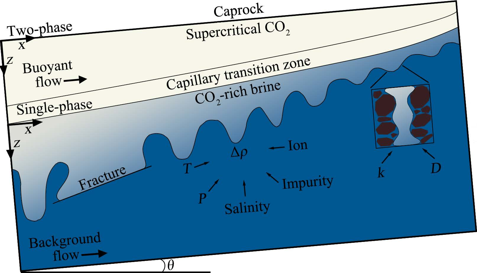
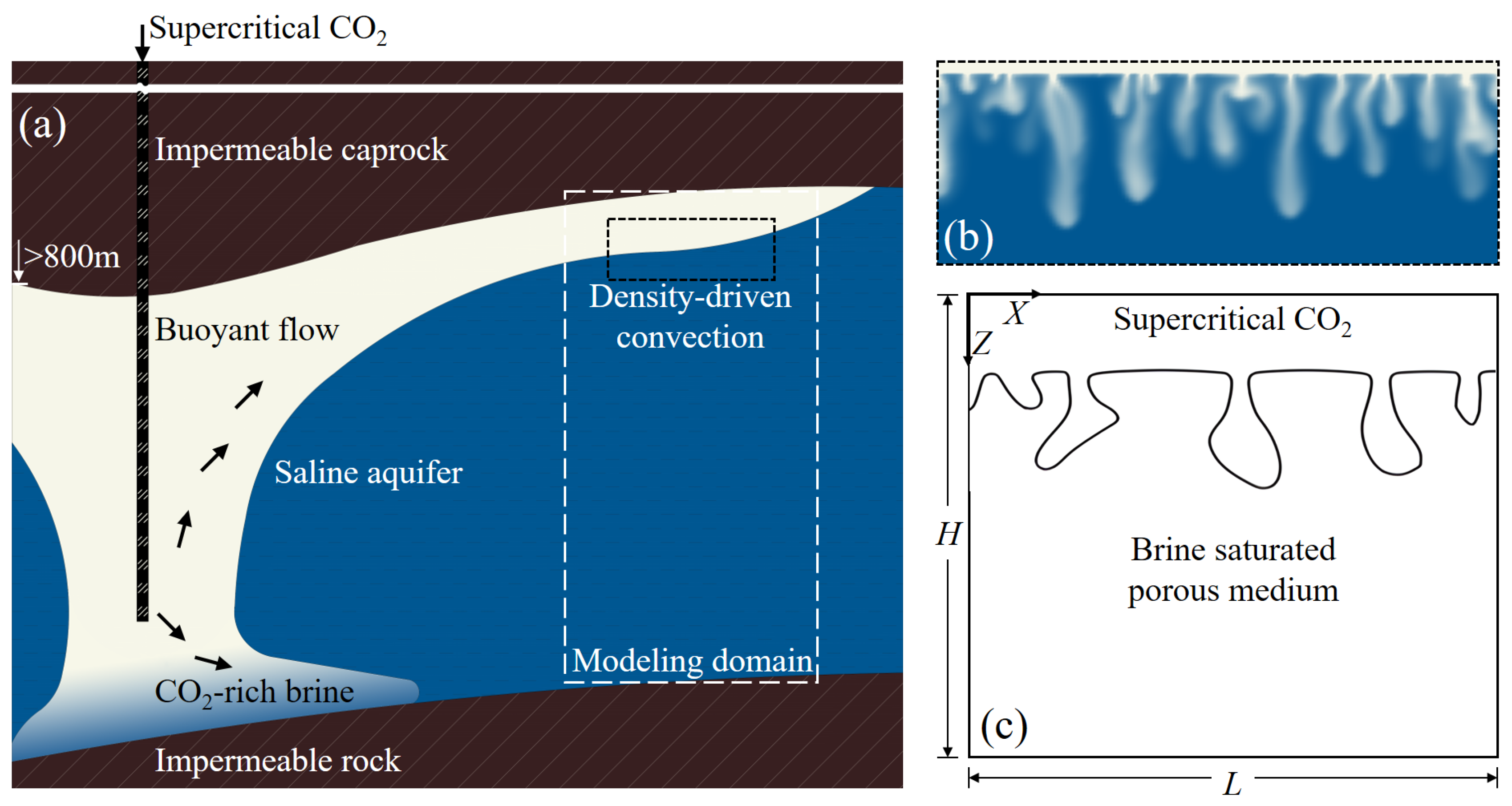
Figure 1 illustrates the typical modeling setup for CO2 solubility trapping in a saline aquifer. The spatial characteristic of the saline aquifer is that the horizontal length is much greater than the vertical depth, so the influence of the lateral boundary on the convection is insignificant. The convection that is of interest occurs in the space between the lower part of the caprock and the impermeable rock at the base of the saline aquifer, as shown in Figure 1a. Within the limited space of the saline aquifer, more attention was paid to the vertical development and horizontal migration behavior of CO2-rich brine in convection, as shown in Figure 1b. The rock pore space is initially completely filled with brine. An ideal rectangular porous medium is commonly considered to describe the density-driven convection for CO2 solubility trapping in the saline aquifer, as shown in Figure 1c. The medium is permeable and heterogeneous. Incompressible Newtonian fluids are considered a two-dimensional laminar flow with non-slip boundaries. Moreover, the fluid thermophysical properties (other than density) are considered to be constant.
Single-phase flow system was commonly applied to CO2 density-driven convection [33,34,35]. In this system, the dissolved CO2 no longer exists as a separate phase but as a solute. In most studies employing a single-phase flow system, the fluid flow within the pore space is described by Darcy’s law, and the degree of dissolved CO2 is represented by the concentration for which the mass transport equation is solved. Based on the above perceptions, the continuity equation can be written as follows [36]:
where ϕ is the porosity of the saline aquifer, ρ is the fluid density (kg/m3), t is the time (s), and v is the Darcy velocity vector. The Darcy velocity vector can then be calculated as follows [37]:
where k is the absolute permeability (m2), μ is the fluid dynamic viscosity (kg/(m·s)), p is the fluid pressure (Pa), g is the gravitational acceleration (m/s2), and z means vertical downward is the positive direction.
The mass transfer equation for the dissolution of CO2 into the brine is then given by the following [36]:
where c is the concentration of CO2 (mol/m3), and D is the effective diffusion coefficient (m2/s).
The change of fluid density is very important here, as it causes the convection of the static fluid. Fluid density is normally determined linearly by the CO2 concentration,
where βc is the solute volume expansion coefficient (m3/mol).
It should be noted that the density instability caused by the geothermal gradient prevalent in saline aquifers with large longitudinal scales would trigger extra convection, which, jointly with the convection generated by CO2 solubility trapping, was known as double-diffusive convection and has been extensively studied [38,39,40,41,42,43]. By introducing an energy balance equation to account for this temperature-induced extra convection, we obtain the following [44]:
where ch is the specific heat capacity (J/(kg·K)), T is the fluid temperature (K), and km is the effective thermal conductivity of porous medium (W/(m·K)). (ρch)m = ϕ(ρch)f + (1−ϕ) (ρch)s represents the effective heat capacity, and the subscripts m, f, and s refer to the matrix, fluid, and solid phase, respectively. Thus, Equation (4) becomes as follows [45]:
where βT is the volumetric thermal expansion coefficient (1/K). However, Javaheri et al. [39] pointed out that the effect of the geothermal gradient on density-driven convection was negligible compared to the solute effect caused by the dissolution and diffusion of CO2 in saline aquifers. Thus, modeling for CO2 solubility trapping in saline aquifers could be postulated as isothermal in terms of density-driven convection.
The fluid viscosity also increased slightly with the CO2 concentration, which affected density-driven convection, as shown in Equation (2), and could be quantified as a monotonic logarithmic relationship for concentration [46]:
where μ0 is the dynamic viscosity for c = c0, and Γ is the viscosity variation parameter. However, the viscosity difference caused by this change was rather insignificant [47,48,49]. Although it has been suggested that this difference in viscosity would trigger similar transversal convection (called viscous fingering) at the base of the saline aquifer caprock during the initial stages of CO2 injection [50,51,52,53,54], the change in density was apparently more significant compared with the change in viscosity during the stage when CO2 stabilized and began to dissolve [55,56,57]. Therefore, the change of viscosity is generally ignored in the modeling of the convective flow.
However, the geological storage of CO2 involves multicomponent and multiphase processes, and, similarly, the convective mixing process is also a multiphase-involved process. The results based on multiphase flow were shown to be different from those of single-phase flow [58,59,60]. The simplification of single-phase systems would pose problems and lead to biased conclusions for density-driven convection. It is suggested that the accuracy of the results of convective mixing process studies could be effectively improved by considering multiphase flow, as well as permeability field variations [61,62]. The modeling using simplifying assumptions might cause the results to be underestimated, while unnecessary assumptions might increase the computational cost. Emami-Meybodi et al. [63] pointed out that the single-phase system ignored the transversal flow of CO2-rich brine at the interface and the volume expansion of brine caused by CO2 dissolution. This would lead to an overestimation of the convection onset with an underestimation of the CO2 dissolution flux. A series of investigations [62,64,65,66,67] further showed that a two-phase flow system would correct the misestimation of convective onset time and dissolution flux. This implied a more-than-three-times increase in the CO2 convective dissolution flux, along with a three-to-six-times reduction in the onset time of convection.
The two-phase system of saline aquifers is formed by the non-wetting phase CO2 and the wetting phase brine. To introduce the concept of saturation, the continuity equation can be written as follows [68]:
where the subscript i is the phase involving the non-wetting phase (nw) and the wetting phase (w), Si refers to the phase saturation, ρi is the phase density (kg/m3), and Iic refers to the rate of CO2 mass transfer by the interface of two-phase (kg/(m3·s)). Moreover, vi is the Darcy velocity vector of the phase, which can be calculated as follows:
where kri is the relative permeability of the phase, μi is the dynamic viscosity of the phase (kg/(m·s)), and pi is the pressure of the phase (Pa).
The distribution for CO2 in brine is then given by the following [69]:
where mwc is the CO2 mass fraction in the wetting phase, Dwc is the CO2 diffusion coefficient in the wetting phase (m2/s), and Iwc refers to the rate of CO2 mass transfer by the interface of two-phase to the wetting phase (kg/(m3·s)).
The above equation is closed by the Brooks–Corey model [70]:
where Se is the effective saturation; Snwr and Swr are the residual saturation of the non-wetting and the wetting phase, respectively; λ is the Brooks–Corey coefficient; and pc and pd are the capillary and pore-injection pressure, respectively (Pa).
Zhang et al. [71] further adopted the three-phase model, meaning that the rock as the matrix of porous media was also considered as an independent phase. Although the influence of geochemical reaction on density-driven convection was accommodated based on this consideration, the discussion of it even exceeded the dissolution effect and should be investigated in the relevant content of CO2 mineral trapping in a saline aquifer.
2.2. Coordinate Selection and Boundary Conditions
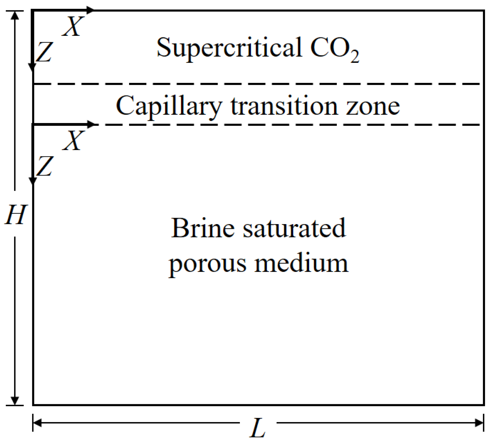
For a more realistic simulation of CO2 density-driven convection development in a saline aquifer, the two coordinate settings proposed based on the 2D physical layout represent different degrees of consideration, as shown in Figure 2, which will induce the discussion of top-boundary conditions.
When the injected CO2 contacts the brine in a saline aquifer, a zone forms at the interface of these two miscible phases. It is governed by a combination of capillary forces with gravity and is called the capillary transition zone. In this zone, CO2 coexists in equilibrium with brine and freely flows, and the CO2 effective saturation decreases nonlinearly in the gravitational direction [67,72]. Thereafter, the free-phase CO2 becomes a solute of brine by dissolution, contributing to the diffusion boundary layer in the lower part of the capillary transition zone. The consideration for the presence of the capillary transition zone therefore determines whether the model is a multiphase system.
The coordinate system built on the lower part of the capillary transition zone almost corresponds to the single-phase system. By ignoring the capillary transition zone between the gas and liquid phase, the CO2–brine interface could be sharp and fixed. Therefore, only the liquid phase is modeled, and the CO2 that accumulates at the top of the aquifer saline is represented as a top boundary condition with a fixed value. A constant concentration top boundary condition is employed in most studies accordingly, with the CO2-pure and -rich region in the upper part of the saline aquifer being replaced by an impermeable concentration boundary with the value of the maximum dissolved concentration under initial conditions. This simplification might lead to the neglect of multiphase processes affecting CO2 density-driven convection, such as capillary effects, upward transport and volume expansion of brine, and decreases in CO2 phase partial pressure [62,63,73,74,75]. On the other hand, Amooie et al. [35] mentioned the constant flux boundary condition. They pointed out that density-driven convection based on both top boundary conditions developed a quasi-steady state to balance the formation and merging of the CO2 plume. For the constant concentration boundary condition, the quasi-steady state is typically represented by a plateau in dissolution flux, but this would not apply to the constant flux boundary condition. Furthermore, in the case of the constant flux boundary condition, the changes in maximum density and concentration were time dependent.
On the other hand, the coordinate system established at the top considers the presence of CO2 as a separate phase, implying a two-phase system, and thus additionally considers the capillary transition zone. CO2 is in contact with brine through microscopic pores in the zone, and the two fluids are in equilibrium, with the average fluid density increasing from the density of CO2 to the CO2–brine solution density in maximum equilibrium. The phase interface in the two-phase system was commonly defined as the interface separating the brine-saturated zone from the capillary transition zone [62,66]. The capillary pressure increases from 0 at the interface, and the CO2 dissolution flux is controlled by the mass transfer via the interface. A separate CO2 single-phase region with a constant permeability different from the brine-saturated porous media is considered a capillary transition zone [64,66,76,77].
The capillary transition zone permitted CO2–brine flow to cross the phase interface longitudinally, which increased the instability of the system [66,78]. This accelerates the onset of density-driven convection even up to several times [62,64,65,66,67]. Zhang et al. [78] similarly noted that the capillary transition zone destabilizes the diffusion boundary layer by allowing transversal flow through the phase interface. However, further investigations on the influence of the capillary transition zone on the CO2 density-driven convection development are awaited.
In the actual aquifer, natural background flow is always present [79,80], which will probably have an impact on CO2 sequestration. The background flow is taken into account in the modeling of CO2 density-driven convection by the laterally fixed velocity boundary condition [81,82,83,84]. The intensity of the background flow is characterized by the value of the fixed velocity, v0, or Peclet number,
where v0 is the transversal velocity of background flow (m/s), and H is the height of the porous medium (m). The larger transversal flow due to background flow would allow mixed convection to play an important role in CO2 solubility trapping. In mixed convection, the background flow in saline aquifers prevents the construction of the longitudinal velocity field of the CO2–brine solution and may delay or even inhibit density-driven convection from occurring [82].
3. Influencing Factors
To accurately perceive how CO2 behaves in the subsurface after it has been injected into the saline aquifer, the influence of various factors on convection must be taken into account, and these factors can be divided into two categories. One category of factors directly affects the hydrodynamics of convection, often those of reservoir characteristics. Another category of factors relates to the dissolution dynamics of CO2 in the saline aquifer. These factors generally include fluid properties, which affect the pattern of changes in fluid density by influencing the CO2 dissolution process, thus determining the convection process. This section describes the impact of these factors on the convection process based on the CO2–brine system.
3.1. Fluid Dynamics
3.1.1. Permeability
Fluids within porous media flow and transfer mass through the interstices of particles. Permeability indicates the degree of difficulty in passing fluids through porous media. Its value depends on the porous structure of the media and is an important characterization parameter for the properties of porous media. A porous medium composed of geological rocks with a certain degree of permeability is a prerequisite to ensure that density-driven convection of brine occurs. In general, density-driven convection for CO2 solubility trapping in saline aquifers can be determined by the Rayleigh number. When the Rayleigh number exceeds 4π2 [85,86], convection will occur:
where Δρ is the maximum density difference between CO2-rich brine and CO2-free brine (kg/m3). Ra is an important parameter for quantifying convection in porous media and is expressed by the ratio of buoyancy to diffusion forces. It determines the intensity of fluid flow and mass transfer in convection, and convection with different Ra presents differences in fluid flow and development characteristics. It is easy to see from Equation (13) that Ra is determined by the properties of the porous medium and fluid, which vary with the location of the CO2 sequestration. For these parameters, only the variation in permeability across different trapping sites is of orders of magnitude, meaning that Ra, or the state of density-driven convection for CO2 solubility trapping in the saline aquifer, is highly dependent on the permeability value of the local saline aquifer. This is further illustrated by the research of Pau et al. [33] on the influence of parameter fluctuation on the initial stability of CO2 density-driven convection, where the initial stability of the CO2–brine system showed high sensitivity to slight fluctuation in permeability. Furthermore, they found that the dissolution flux of CO2 at the top boundary would reach a steady state after a certain time. This flux was proportional to permeability, unrelated to effective diffusion coefficient and porosity, indicating that the flow was predominantly convective.
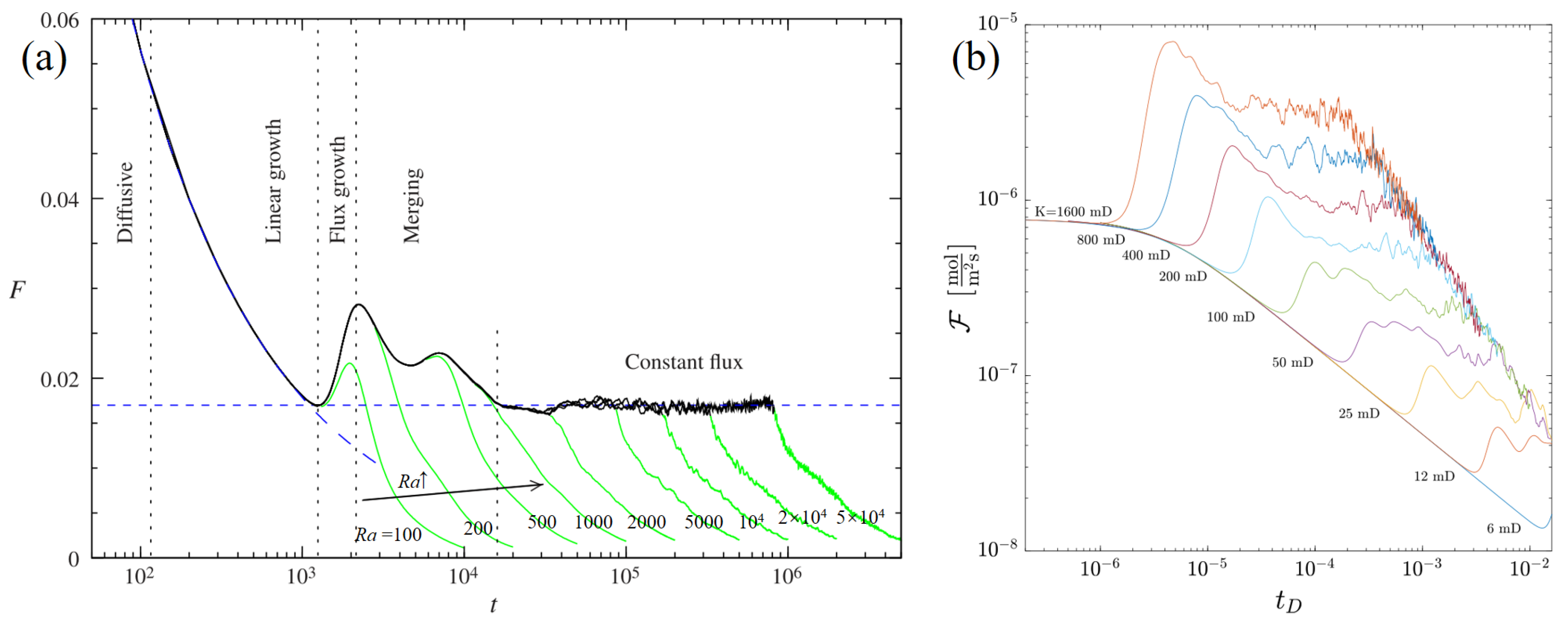
The analysis of CO2 dissolution flux allows the description of the important dynamic behavior of CO2 convection processes caused by changes in aquifer conditions. Slim [77] described the hydrodynamics of CO2 density-driven convection from the diffusion to the shutdown in a two-dimensional porous medium with Ra between 100 and 5 × 10⁴. From the time-dependent profile of the dissolved CO2 flux at the top boundary, this convective process was described in six stages, and it is found that Ra controlled the transition of convective stages and the mass transfer characteristic of convection within the different stages. Moreover, as the permeability of the porous medium increased, convection delayed the time to end the constant flux stage, as shown in Figure 3a. Erfani et al. [87] further gave dissolution flux for different permeabilities corresponding to Ra from 350 to 95,000, as shown in Figure 3b. As the permeability increased, there was a significant advance in the onset of convection with a corresponding increase for the maximum CO2 dissolution flux during the flux growth stage. In general, as the permeability of porous media increased, density-driven convection would become more intense, not only in terms of an earlier onset of convection, but also in terms of a longer flux growth stage, which meant that the maximum dissolution flux of CO2 would also increase significantly. In addition, the convection would experience a longer period of merging. CO2 convection would also undergo a constant flux stage in porous media with high permeability, and this would be more pronounced at higher permeability, implying a later shutdown of convection and a higher level of CO2 dissolution and mixing.
The morphological characteristics of convective fingering movements can also be used to determine the state of convection. Teng et al. [88,89] investigated density-driven flow transport processes by magnetic resonance images. It was found that, as the permeability increased, the rate of convection development and the amount of convective fingering increased, with an earlier onset of convection. Numerical simulations by Ching et al. [90] showed a significant increase in the wavelength of convective fingering in high-permeability porous media, while experimental results by Amarasinghe et al. [91] showed that the mixing rate of CO2 convection in porous media increased with increased permeability. It was also observed that the morphology of the convective fingering of CO2 depends on the permeability, with the observed fingering in highly permeable porous media being consistent with previous studies, in contrast to the piston displacement of brine with dissolved CO2 in low permeability porous media (e.g., 500 mD).
However, actual saline aquifers are heterogeneous, and this heterogeneity in reservoir conditions, particularly in permeability, will significantly affect the mixing process of density-driven convection. The flow characteristics of the mixing due to convective processes depend on the aquifer permeability heterogeneity. Thus, when considering convection in heterogeneous porous media, spatial variation in permeability is often used to introduce heterogeneity, which means that the absolute permeability, k, in Equation (2) will become k(x, z) or a tensor.
The degree of heterogeneity of reservoir permeability can be expressed by the value of fluctuation in the random field attached to the permeability. In the CO2- brine model of Pau et al. [33], the onset time of convection exhibited sensitivity to the magnitude of fluctuation in the permeability field, with the convective onset time decreasing as the magnitude of fluctuation increased. However, this decreasing trend is gradually diminishing; when the fluctuation reaches 15% or higher, the onset time of convection shows a certain degree of certainty. Lengler et al. [92] used a similar stochastic approach to create a spatially varying permeability field for a real CO2 sequestration site. In their random field, the permeability values varied from 0.02 to 5000 mD, resulting in reservoirs with permeability heterogeneity having higher CO2 dissolution storage capacity compared to homogeneous reservoirs. On the other hand, Mahyapour et al. [18] used sequential Gaussian simulation methods to generate stochastic permeability fields to elucidate the influence of permeability heterogeneity for CO2 convection in saline aquifers. Convective results in the stochastic permeability field showed that an increase in permeability fluctuation enhanced the CO2 dissolution flux and the tendency for convective fingering.
The Dykstra–Parsons coefficient and correlation length were also considered as the measure of the degree of permeability heterogeneity. The permeability variation was first introduced by Dykstra and Parsons [93] to quantify the degree of reservoir heterogeneity:
where Sk and Ak are the standard deviation and the average value of k, respectively. Vk is the so-called Dykstra–Parsons coefficient, a dimensionless measure for the variability of porous media that characterizes the heterogeneity of k [94]. Values for Vk range between 0 for a completely homogeneous aquifer and 1.0 for a completely heterogeneous aquifer. In between, it is generally suggested that when Vk was less than 0.25, the heterogeneity of the aquifer was slight and could be approximated by the homogeneous model in numerical simulation. As 0.25 < Vk < 0.75, the influence of the aquifer heterogeneity was gradually significant. Once Vk exceeded 0.75, the aquifer was extremely heterogeneous and required special treatment methods for numerical simulation. Note that Sk and Ak usually tend to vary in tandem; thus, Vk is relatively constant in a saline aquifer. Bestehorn et al. [95] examined permeability heterogeneity over a wide range, using Vk and correlation lengths. The results pointed to the convective onset time being significantly correlated with perturbation strength and correlation length. Using different degrees of permeability heterogeneity achieved by spectral methods, Farajzadeh et al. [96] identified different flow states characterized by Vk for density-driven convection. For a smaller Vk (0.1), convective fingering close to the same occurrence in homogeneous porous media was observed. However, even though the phenomena are similar, CO2 dissolution in the heterogeneous porous medium generally occurs in larger quantities as compared to the homogeneous ones. Convection in heterogeneous porous media with a larger Vk (0.3, 0.5, and 0.8) exhibits more direct mass transfer than convective fingering. The different patterns exhibited by density-driven convection at different heterogeneities are thus classified into three groups: fingering, dispersive, and channeling. Chen et al. [97] noted that, in dispersion, the square of the dissolved mass of CO2 was approximately proportional to time, while the dissolved mass of CO2 is approximately proportional to time in both fingering and channeling. However, fingering was largely controlled by gravitational instability, while channeling depended on the permeability structure.
Similarly, these three patterns of density-driven convection were observed in the heterogeneous saline aquifers of Ranganathan [98] and Kong et al. [99], with the latter referring to these three flow patterns of density-driven convection as dispersive, preferential, and unbiased fingering. It was noted that the unbiased fingering converted to preferential and dispersive fingering was largely dependent on Vk, while the preferential fingering converted to dispersive fingering was determined by the length of the permeability dependence.
The dissolution flux and convective onset time of CO2 certainly increase with increasing permeability heterogeneity regardless of how heterogeneity is introduced and evaluated in the CO2–brine system. This indicates that the introduction of heterogeneity introduces more instability, dissolution rates, and flow opportunities to density-driven convection, which will further contribute to the efficiency of CO2 solubility trapping in saline aquifers.
The work by Green et al. [100] also considered two models of permeability heterogeneity. Even though the initial flow state of density-driven convection was sensitive to changes in local permeability, the flow in the constant flux stage of each case was well approximated by the anisotropic homogeneous porous media model. This suggested that the average permeability properties of the porous media actually affected the flow of density-driven convection, meaning that heterogeneity could be expressed equivalently by the permeability anisotropy of a homogeneous porous medium. The consistency between the anisotropic model and heterogeneous porous media in estimating the dissolved mass flux of CO2 by Elenius and Gasda [101] also illustrates this point well. Anisotropy can be described by the anisotropy ratio,
where kv and kh are the vertical and horizontal permeability of the reservoir, respectively. In practical reservoirs, thin structures are often found in saline aquifers, which means that the horizontal permeability is usually much greater than the vertical permeability. Therefore, it is generally reasonable to believe that γ is less than 1.0.
Previous studies [102,103,104] have investigated the effect of anisotropy ratios on density-driven convection by holding kh constant while lowering kv to reduce γ. The results of their stability analysis showed that gravitational instability was mitigated to some extent with decreasing γ, as evidenced by a delay in the convection onset, a decrease in the critical wave number for convective fingering, an increase in the critical wavelength, and a decrease in the CO2 dissolution rate. It is important to note that, although it is geologically more reasonable to keep kh constant, Xu et al. [105] further considered the reduction in γ caused by increasing kh while keeping kv constant. In this case, the reduced γ would instead cause the opposite of the previous conclusion. This is because an increase in permeability, either kh or kv, would destroy the solute interface during CO2 solubility trapping in saline aquifers, resulting in an earlier onset of instability causing higher CO2 dissolution rates. This view was also supported by the results of several numerical simulation studies [87,97,106]. Notably, the results further indicated that the effect of γ on dissolution flux was more significant at a lower value of Ra and permeability of porous medium [107]. It can therefore be established that, regardless of how γ is varied, for kh and kv, while keeping one constant, the higher the value of the other, the more unstable the convection system, the earlier the onset time, and the higher the CO2 dissolution flux. In this process, kv has a more significant effect on density-driven convection than kh.
New representations of permeability anisotropy have recently been proposed. For example, Li et al. [108] represented anisotropic permeability fields in terms of vertical and horizontal correlation lengths, i.e., lv and lh. The results showed that for a relatively small lv and lh, competing phenomena of scale coupling and anisotropy were found, with resonance effects accelerating the downward brine as lh increased to a scale close to the convective fingering, leading to the earlier onset time and correspondingly lower dissolution, while once lh increased to a scale much larger than the convective fingering, anisotropy became the dominant effect so that the onset of convection was delayed. On the other hand, for changes in lv, consistent results of change were observed for relatively large lh, i.e., later onset of convection with higher CO2 dissolution.
3.1.2. Porosity
The rock particles that contribute to the matrix of saline aquifers are normally incompletely integrated due to the highly irregular shape. The resulting void space that can be occupied by CO2 or brine is called pore and quantified as porosity:
where Vp is the pore volume (m3), and Vb is the bulk volume of the matrix (m3), including the solid and void components. Two distinct categories of porosity are defined in saline aquifers, i.e., absolute porosity and effective porosity. Saline aquifers may have considerable absolute porosity with low fluid conductivity due to the lack of interconnected pores. This is negative for CO2 sequestration. Therefore, the porosity in studies of CO2 sequestration in saline aquifers generally refers to the effective porosity.
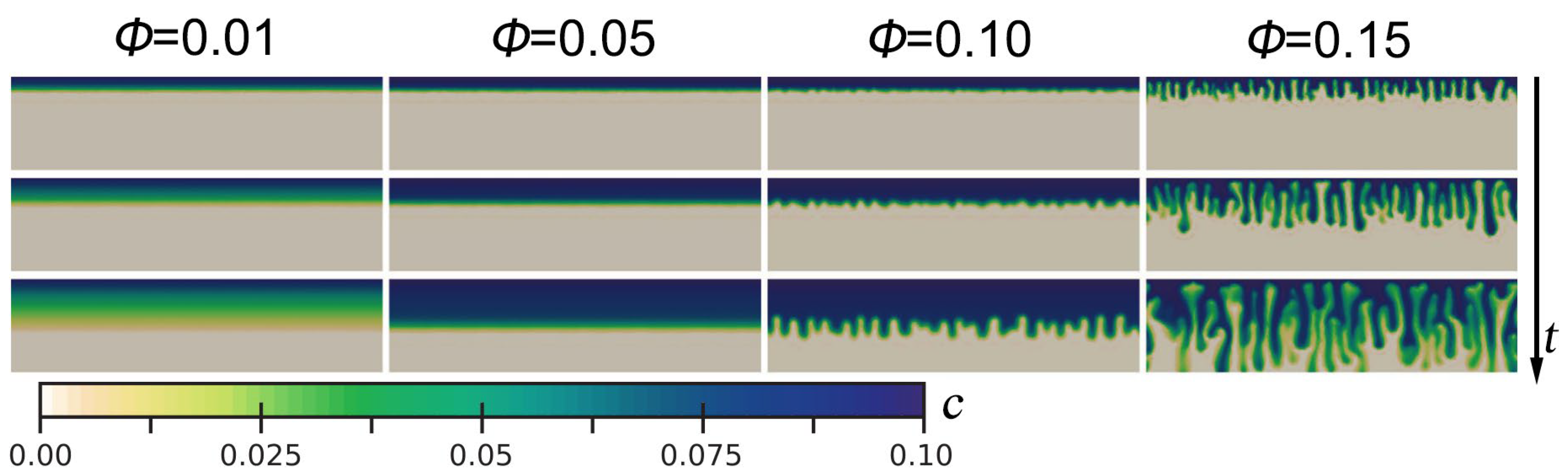
The porosity significantly influences the density-driven convection by controlling the pattern of CO2-rich brine front in saline aquifers. Sun et al. [109] showed that for a low ϕ (less than 0.05), CO2-rich brine maintained the form of a stable boundary layer that slowly diffused downward. In contrast, the instability is further developed in saline aquifers with high ϕ (greater than 0.10), and convective fingering is clearly observed, as shown in Figure 4. The diffuse boundary layer thickness was also influenced by ϕ. A higher ϕ was characterized by a thinner diffusive boundary layer, implying earlier convective onset. The same conclusion was reached by Gasow et al. [110,111].
This increased diffusion instability and decreased convective strength may be explained by the change in the effective diffusion coefficient due to the ϕ. As indicated by the results of Aggelopoulos and Tsakiroglou [112], errors were caused by unconsidered variations in the effective diffusion coefficient due to the ϕ. The effective diffusion coefficient, D, in Equation (3) is thus defined as follows:
where D0 is the molecular diffusion coefficient (m2/s), and τ is the tortuosity. Ozgur and Gumrah [113,114] pointed out that the dissolution of CO2 in diffusion processes increased due to the increase in the effective diffusion coefficient by an increased ϕ. This produced greater instability in the diffusive boundary layer. However, once this increased instability prematurely triggered convection, a reduction in convective strength ensued. This was because the fluid velocity was reduced in aquifers with a high ϕ. More effects of dispersion on density-driven convection are discussed in Section 3.1.5. In addition, Beni et al. [115] pointed out that a change in ϕ would cause a change in k. However, Islam [116] indicated that this change was negligible and therefore would not significantly affect the CO2 density-driven convection.
In terms of heterogeneity, Jensen and Lake [117] pointed out that the spatial variation of ϕ in aquifers was much more insignificant compared to permeability. However, considering that the common geochemical reactions in aquifers would significantly change the local ϕ [118,119,120,121,122,123], a few relevant studies on ϕ heterogeneity were still developed. The ϕ heterogeneity was generally introduced into numerical models as a perturbation (or fluctuation), leading to instability and correlating with convection onset time [124]. Pau et al. [33] pointed out that the onset time decreased by increased ϕ fluctuation, and this decrease was more significant compared to the same degree of permeability fluctuation. The results by Tilton [125] showed that there was an optimal ϕ perturbation that could minimize the onset time. This suggested that even though a small ϕ perturbation was usually neglected, it was sufficient to trigger nonlinear convection. Future studies should take this factor fully into account.
3.1.3. Fractures and Stratification
When there was a certain structure in the heterogeneous permeability field, such as a low permeability or permeability jump zone, the heterogeneous structure of the aquifer would have a greater impact on the total amount of CO2 sequestration compared to the equivalent effective permeability of the aquifers [126]. Typical heterogeneous stratigraphic structures include fractures and stratification. Fractures can be found in several sequestration sites, such as the Salah site in Algeria [127], the Kevin Dome site in Montana [128], and the Janggi site in South Kore [129]. Some sequestration sites will increase injectivity by hydraulic fracturing to increase the permeability of the aquifer or oilfield near the wellbore [130,131]. Fractures imply an intense media anisotropy and preferential flow. The consequent uncertainty in fluid flow and solute transport increased the risk of leakage and contamination [132]. Furthermore, a few numerical simulation studies have been developed for the effect of the fracture-skin on solute transport [133,134]. Except for the naturally existing fractures, the injection of CO2 will lead to artificial fractures in saline aquifers. This occurs due to the increased pore pressure, and the reduced effective stress will result in geo-mechanical deformation. This deformation may also reactivate faults and change permeability to affect the integrity of the reservoir [135]. During the injection process, related studies have revealed that the presence of fractures, whether artificial or natural, can provide the escape pathways for undissolved CO2 in a saline aquifer, negatively affecting the long-term secure storage of CO2 [21,22,136]. On the other hand, the presence of the fractures creates a large contact area between CO2 and brine, thereby facilitating the dissolution of CO2.
In the studies of solute transport by density-driven convection in fractured formations, the models of single fracture and the fracture network were considered. Compared with the complex fracture network, the single fracture is often treated as a simple system to study the transport between the fracture and the matrix [137]. Graf and Therrien [138] found that a continuous 45° inclined single fracture in a low-permeability matrix system allowed solutes to penetrate through the fractures and migrate downward. Iding and Blunt [139] found that the dissolution rate of gas-phase CO2 in the system could be increased by 5% by inletting a horizontal single fracture in a 2D model, indicating that fractured aquifers were able to increase the solubility trapping of CO2. Rezk and Foroozesh [19] used numerical simulations to find that high permeability and big inclination angle of fractures favored the CO2 solubility trapping process in the single fracture system. Similar findings were found by Kim et al. [140] that a small inclination single fracture structure in the aquifer enhanced the mass transfer between the fracture and matrix, while the large inclination fractures promoted brine movement toward the top boundary, facilitating circulation in the region and enhancing CO2 dissolution.
The permeability of matrix and fracture also has an impact on CO2 solubility trapping. Kim et al. [140] investigated the effects of fracture–matrix permeability ratio on convection. When the permeability values of the matrix and the fracture are similar, the influence of fracture on density-driven convection was negligible. In addition, the intersection of two fractures was found to promote the merging of fingering, which enhanced the mass transfer between fractures. Wang et al. [17] showed that the higher permeability of fractures was favorable to solubility trapping, and the greater inclination angle was favorable for mixing between the two-phase fluids. In addition, when the permeability of the fractures was smaller than the matrix, the fractures acted as flow barriers in the system, hindering the fingering development. When the permeability was larger than the matrix, the fractures enhanced the liquid-phase circulation, allowing more brine at the bottom boundary to enter the top region of the fractures.
In a fracture network consisting of multiple fractures, the transport of the plume tends to be much more complicated. The results by Shikaze et al. [141] showed that convection patterns depended on fracture spacing. In porous media with random fracture spacing, irregularly shaped convective cells were formed. The intricate convection patterns were also found in porous media with orthogonal fractures, regardless of the uniform spacing and pore size of the fractures. In addition, it is suggested that solute migration and mass transfer rates properly not be predicted in complex fractured formations. The above findings suggest that the geometry of fractures is highly related to the stability of density-driven convection within the fractured system. Graf and Therrien [142] investigated the dense plume transport in the orthogonal and irregular fracture networks. The geometry of the porosity network had a significant impact on the dense plume transport. In the orthogonal network, the variable density flow was mainly controlled by the convective patterns found in the large fracture network. In an irregular fracture grid, density-driven transport was favored if there were few uniformly distributed fractures close to the source. On the other hand, a large number of fractures near the solute source had a stabilizing effect. Vujevic et al. [143] investigated the density-driven flow and transport patterns in uninterrupted, interrupted, perpendicular, and inclined fracture networks in low-permeability matrices. The results revealed that the influence of irregular networks on stability was more difficult to predict than that of regular networks, but it was possible to determine that the average length of fractures had a greater influence on density-driven convection than the distribution density of fractures.
In fractured formations, a 2D fracture is essentially represented by a line, so convection within the fractures is disregarded due to this restriction on the spatial dimension. Although the fractures models used in the previous studies have small apertures, making their permeability vastly different from that of the reservoir matrix. There was evidence that an increase in fracture aperture increased the velocity of the upward flow of brine within the fractures, leading to an increase in early convective instability [144], which favored CO2 solubility trapping [19]. The results also implied that the heterogeneity of permeability between the fracture and matrix might have a dramatic influence on the flow pattern in the convective mixing process. Moreover, it has been suggested that both the flow between fractures and the storability of the fractures play a significant part in the stability behavior of the system, and the convection within the fractures may have an impact on CO2 solubility trapping. However, currently, the relevant studies are still lacking. One of the reasons may be attributed to the fact that it is challenging to study in different dimensions in fractured systems considering the heterogeneity, especially in more complex 3D systems, and that the consistency between 2D and 3D results needs to be further demonstrated. Vujevic and Graf [145] tried to study the convective behavior within fractures by using a 3D model and found that the mass transport between fractures was greater than within fractures. However, in the more complex 3D fracture networks, it was difficult to use the Rayleigh criterion to predict the convective behavior. Only under specific conditions were the 2D results useful for predicting the convective onset time and intensity in a 3D fracture network. In addition, the impact of the physical properties of the fracture (e.g., roughness, tortuosity, etc.) on the convection in the fracture system has not been fully understood. Note that the current study of CO2 solubility trapping in fractured systems is mainly focused on single-phase flows, and further study of two-phase flows, especially from the beginning of injection to the post-injection, involving the drainage process, capillary action, and reinfiltrating phenomena, is more helpful to understand the convection behavior in the fracture network.
Stratification is another common heterogeneous structure, and the influence of such aquifers with a certain number of different permeability layers on convection has also gained much attention in recent years. It is suggested that low permeability zones in saline aquifers play an important role in avoiding CO2 leakage [146,147]. At the same time, the heterogeneity of the layering permeability affects the migration of injected CO2 and the subsequent process of mass transfer [121,148].
Wang et al. [149] used the non-destructive technique of X-ray micro-tomography to capture the fingering development process in the 3D layered formation and found that the wavelength of fingering increased when fingering passed through the stratified interface in the decreasing-permeability aquifers. By using a numerical modeling method in multilayered porous media, Farajzadeh et al. [150] discovered that when the higher permeability layer was posed at the top layer, the mass transfer increased and fingering moved more quickly as Ra increased. However, the convection weakened as fingering moved into the low permeability layer.
Taheri et al. [151] defined the concept of strong and weak heterogeneity by the magnitude of the ratio of the permeability in the upper and lower layers. It was found by numerical simulation methods that when the low permeability layer was in the upper layer, either strong or weak heterogeneity, the upper layer controlled the convection behavior of the whole system. When the upper layer was a high permeability layer, the upper layer also acted as a control layer in the weak heterogeneous system. However, in strong heterogeneous systems, the lower permeability of the lower layer facilitated the dissolution of more CO2. This work was later extended by upgrading the Hele-Shaw to study convection in a two-layer heterogeneous system [152]. It is found that when the high permeability layer was posed above the low permeability layer, the dissolution rate would be more than twice as large as that in a low-permeability homogeneous system. This implied that the higher permeability upper layer facilitates the rapid dissolution of CO2 in brine. Agartan and Trevisan [153] used a laboratory tank with analog fluids to study density-driven convection. It was found that the process of diffusive mixing would be more pronounced than density-driven convection in the stratified formations and that a longer retention time in the lower permeable layer might favor long-term secure storage of CO2. Similar findings were also found in the laboratory experiments by Wang et al. [154], who used magnetic resonance imaging techniques to visualize the evolution of convection in multilayered porous media. It was found that the permeability heterogeneity had a significant impact on the dissolution rate of CO2, and the presence of low permeability layers hindered the fingering flow and decreased the dissolution rate of CO2 but promoted the transversal diffusion of the permeable transition region.
In addition to the slope caprock, as mentioned earlier, there is a certain inclination at the stratified interface in the actual aquifers, which may also affect the convection. Tsai et al. [155] found that, compared with the horizontal case, the presence of the inclined stratified interface increased the propagation velocity of fingering by about 20%. Both Agartan et al. [153] and Wang et al. [156] used tank experiments to investigate the convection in the inclined stratification aquifers, and they found that the presence of an inclined interface altered the behavior of fingering. For example, in the coarse/fine layers system, fingering migrated along the lower part of the stratified interface, enhancing the fingering spreading in the vertical direction. Unfortunately, there are no available studies focusing on the specific behavior of fingering and the mass transport during convection within the inclined layered system. Moreover, the transformation involving convective dissolution processes at multiple spatial and temporal scales associated with CO2 sequestration in saline aquifers poses a challenge to the widespread application of it. Macroscopic spatial scales up to thousands of meters and has a timescale of up to hundreds or thousands of years. Related results suggested that the heterogeneity of pore size and wettability altered the inherent flow permeability of the stratified structure [157]. The transport of dissolved CO2 was intimately related to pore geometry, and the difference in solute distribution between large and small pores dramatically influenced the upscaling process, making the study of pore scale vital [158]. Therefore, this challenge is faced in both laboratory experiments and numerical simulations. To consider the effects of the multiphase and multicomponent flows occurring at the actual CO2 sequestration field, as well as the possible geochemical reactions, and geo-mechanical effects, the appropriately fine-scale discretization may need to be used in the numerical model to obtain an accurate result to assess the effectiveness of CO2 sequestration in the stratification formations, which is a topic worth discussing in the future.
Different lithologies are associated with the stratification of aquifers, which affects structural geometry and aquifer properties (e.g., permeability and porosity) [159]. Take the White Rim Sandstone reservoir as an example; Wheatley et al. [160] explained the relevant reservoir characteristics (e.g., sedimentary structure, facies, and diagenesis). Seven independent litho-facies were used to describe the White Rim Sandstone: grain-flow facies, wind-ripple facies, ripple-laminated facies, soft-sediment deformation facies, symmetrically ripped facies, bioturbated facies, and massive facies. They discovered that the quantity and relative spacing of internal laminae or boundary surfaces that were horizontally or obliquely oriented, which impeded fluid flow, accounting for a major portion of permeability variances in facies. White et al. [159] compared the potential reservoirs, including Jurassic Navajo Sandstone, Jurassic Wingate Sandstone, Permian White Rim Sandstone, and Mississippian Redwall Limestone, and found that the Permian White Rim Sandstone was the best reservoir for CO2 injection, with great permeability and porosity. In fact, it was not rigorous to judge the applicability of geological storage based on permeability and porosity. The composition of the rocks, sedimentary diagnostic eolian features, thickness and depth of the layers, etc., should all be considered [161].
In addition, transmissibility plays an important role in the stratification and subsequent fault of aquifers. It implies a measure of how much brine can be transmitted horizontally and is commonly present in studies of aquifers with pumping behavior [162]. The transmissibility of an aquifer can be defined as follows:
where Tt is the total transmissibility of the aquifer (m2/day), Ti is the transmissibility of a horizontal flow for the ith aquifer layer, Ki is the horizontal hydraulic conductivity, and di is the layer thickness.
The transmissibility multiplier was commonly used in studies [163]. A transmissibility multiplier of 0 implied that the fault was sealed, and therefore the flow across the fault zone is considered to be restricted. A transmissibility multiplier of 1 implied that the fault zone was free-flowing, similar to the rock matrix. Alexander et al. [164] noted that a transmissibility multiplier significantly affected the amount of CO2 that could be injected into an aquifer and ultimately stored. For a transmissibility multiplier of less than 0.01, the injectable CO2 was completely stored. This was because the injected CO2 was not reaching the production well and therefore remained in an aquifer. For a transmissibility multiplier greater than 0.01, the amount of injectable and stored CO2 increased linearly. For a transmissibility multiplier greater than 0.1, the amount of stored CO2 was almost constant, although the amount of injectable CO2 still increased dramatically. Therefore, a transmissibility multiplier between 0.01 to 0.1 seemed to be the optimal range for CO2 sequestration in saline aquifers.
However, Hsieh et al. [165] suggested that a saline aquifer with an optimal transmissibility multiplier might not be the best option for CO2 sequestration safety. Other risks still need to be assessed in order to find the best solution. Based on this perception, Ghanbari et al. [166] pointed out that the key to the distribution of CO2 plume and solute was not the transmissibility multiplier; instead, it was the location of the injection well.
3.1.4. Slope of Caprock
The fact that saline aquifers are generally tilted and discontinuous may have an impact on the convective process in CO2 solubility trapping. Given the differences in scale, the influence of saline aquifer structure on density-driven convection occurs more often at the upper and lower boundaries, i.e., at the caprock or the bottom impermeable rock layer (Figure 1a). Here, the caprock is a prerequisite for the successful retention of injected supercritical CO2, providing the potential for the occurrence of dissolved sequestration and later density-driven convection. For a long period of time, the injected CO2 will remain and migrate as a plume at the bottom of the caprock under buoyancy, and the state of the caprock will still have an impact on the flow and mass transfer of density-driven convection even after the stage of solubility trapping. On the other hand, Vilarrasa et al. [167] pointed out that the effect of the inclined impermeable rock layer at the bottom of the saline aquifer acted only after the convective fingering front in density-driven convection contacted the rock. Therefore, the caprock is considered to be the primary target for considering the effect of saline aquifer slope and integrity on CO2 solubility trapping.
In the study by Tsai et al. [155], the tilt of the saline aquifer was considered an inclined modeling domain, and numerical simulations showed that a sloped boundary would enhance density-driven convection, as reflected in the large transversal movement, merging, and coarsening of the convective fingering, which enhanced convection and implied that a sloped saline aquifer would be the ideal site for CO2 solubility trapping. However, Macminn et al. [168] found that a small slope of the caprock was indeed beneficial for CO2 solubility trapping, resulting in a sharp reduction in the time that the CO2 plume was present, with the maximum transport distance only slightly increased. However, a continued increase in slope would still pose some risks, such as greater increases in transport distance and very little reduction in the time the CO2 plume was present. Even though residual trapping provided a strong complement to density-driven convection in solubility trapping, the increase in slope was expected to still expose the CO2 plume to fresh water and cause pollution.
Sung et al. [121] evaluated the potential for an ideal CO2 geological sequestration site, and their study noted that the prevalence of tilted saline aquifers in sequestration sites would significantly affect the fate of injected CO2, resulting in a marginal asymmetry of CO2 plume in the direction of upslope, as shown in Figure 5. Meng and Jiang [25] considered the inclined saline aquifer as the slope of the top boundary of the modeling domain. For both 2D and 3D numerical simulations, as the slope of the caprock increased, the diffusion of the boundary layer became smoother, and the number of convective fingerings decreased, and this was accompanied by a significantly different fingering merging behavior than in the horizontal caprock case. While the interaction between fingering weakened and the flow showed more reliance on the direction of the caprock slope. This implies a more stable density-driven convection, as the component of gravity in the slope direction increases with the increasing caprock slope, thus making it more difficult for the top boundary layer to satisfy the thickness for sufficient instability. Note that the slope of the caprock in the 3D numerical simulations would result in a later onset of convection than the horizontal caprock case for the same reservoir, and this effect was more pronounced than in the 2D numerical simulations.
In general, the influence of a tilted saline aquifer on the fate of injected CO2 is mainly reflected in the effect of the caprock slope on CO2 plume flow and density-driven convection. The presence of a caprock slope will cause the CO2 plume to migrate upslope under buoyancy, meaning that, even if there are benefits, the slope of the caprock should not be overly steep. Because the overly steep slope often implies an unexpectedly large migration of the CO2 plume and the consequent risk of CO2 exposure to fresh water, it is contrary to the original intention of CO2 solubility trapping in saline aquifers to isolate it from the atmosphere and to limit its migration. However, a slightly sloping caprock may have an advantage in that once solubility trapping is dominant, density-driven convection will be intensified, as evidenced by the transversal migration of convective fingering downslope by both gravity and slope, as well as the consequent consolidation and coarsening of fingering. This will greatly facilitate the process of density-driven convection and ensure efficient CO2 solubility trapping to further secure CO2 sequestration in the saline aquifer.
3.1.5. Hydrodynamic Dispersion
The mass transfer of mechanical dispersion, jointly with molecular diffusion, is widely present in aquifers [169] and is called hydrodynamic dispersion [170,171,172]. Note that hydrodynamic dispersion is generated by the local variations in fluid velocity due to the micro- and/or macroscopic heterogeneity and structure of the porous media, such as friction on the pore walls, heterogeneous pore sizes, and different trajectories, and presents an enhancement of dissolution [173] with the heterogeneity of velocity. This velocity heterogeneity will enhance molecular diffusion, which has a substantial impact on solute migration, also known as mechanical dispersion. Therefore, when the effect of mechanical dispersion is considered, the effective diffusion coefficient, D, in Equation (3) should be given by the hydrodynamic dispersion tensor as follows [174]:
where δ is the Kronecker delta; αl and αt indicate longitudinal and transversal dispersity lengths, respectively (m); and subscripts x and y refer to the axes of the Cartesian coordinate system. The first part on the right of the equation is a representation of the effect of molecular diffusion, where D0 is a constant that takes into account the volume diffusion coefficient with the tortuous effect of the porous medium and is proportional to the local gap velocity. The second and third parts are the effects due to mechanical dispersion. In most analyses of hydrodynamic dispersion, Equation (19) is usually given in the dimensionless form, which leads to different dimensionless parameters being derived to characterize the effects of dispersion, commonly the dispersion ratio, α, and the longitudinal dispersion strength, S. The dispersion ratio characterizes the degree of mechanical dispersion anisotropy of porous media and is usually expressed as follows:
The numerical results by Emami-Meybodi [84] showed that both longitudinal and transversal dispersity had a considerable influence on the fingering patterns and dissolution mass flux. As for α, it represents the ratio of the strength of longitudinal dispersion to molecular diffusion and is given in different forms depending on the purpose of the analysis. In the study by Hidalgo and Carrera [175], the longitudinal dispersion strength was expressed in the following form:
where ub = kΔρg/μ is the velocity scalar (m/s), also known as the reference velocity. Although they refer to the same α as in Equation (20), it is kept constant at 0.1, which is commonly presented in most subsurface aquifers. The results showed a significant linear reduction in the convective onset time of even two orders of magnitude with increasing mechanical dispersion strength. Ghesmat et al. [176] used the same representation of dispersion, and their results revealed that the presence of dispersion affected the fingering development pattern, with higher dispersion implying faster dissolution of CO2 in brine, enhancing mixing and significantly reducing the convection onset. In addition, the effect of α on density-driven convection was investigated, and the results were similar to the prediction of the numerical study by Xie et al. [177], where aquifers with different dispersion ratios was saturated with dissolved CO2 almost simultaneously, and its overall effect on density-driven convective efficiency was negligible.
However, it is important to note that a dimensionless way of generating this form of S will lead to a non-independence of the dimensionless number, meaning that an increase in S will lead to the same change in Ra. It is consistently agreed upon that an increase in Ra will significantly reduce the convective onset time and increase the intensity of convection, which antagonizes and may easily override the influence of an increasing S on density-driven convection, and this probably explains the significantly reduced convective onset time as S increases. Recent work by Dhar et al. [178] indicated that the convective onset time should increase with S for α = 0.1, which was also consistent with previous experimental results [179,180]. In their simulations, S was independent of Ra according to the following form:
This dimensionless approach may also lead to a more significant role in the dispersion ratio. Their results further suggest that transversal dispersion accelerates this process, implying that an increase in the dispersion ratio promotes the onset of density-driven convection, which seems to be explained by an increase in the dispersion ratio that would destabilize the diffusion boundary layer. Moreover, the increase in transversal dispersion has facilitated the development of transversal growth of the fingering, thus contributing to reducing the density of fingering and possibly tending to homogenize the CO2 concentration field, which is similar to the results of Wang et al. [181,182] and Nakanishi et al. [183]. This phenomenon is attributed to the strength of transversal dispersion between downward and upward flow significantly influencing the interaction, merging, and coarsening of fingering.
Hidalgo and Carrera [175] showed that the onset time of the density-driven convection might be shortened by up to two orders of magnitude when hydrodynamic dispersion was taken into consideration in the no-background flow model. The similar results by Ghesmat et al. [176] demonstrated that the existence of dispersion impacted the fingering development patterns, with larger dispersion meaning faster dissolution of CO2 in brine, this promoting mixing and greatly slowing the onset time of convection.
Particularly, the results of Chevalier et al. [61] revealed that, in the Hele-Shaw cell, an experimental device commonly used to visualize density-driven convection, mechanical dispersion was diminished to a Taylor dispersion due to changes in Poiseuille-type velocity over the cell pore. However, even though the Taylor dispersion increased the hydrodynamic dispersion coefficient by two to five times, it only seemed to retard convection slightly, as expected, because the presence of dispersion tended to reduce the concentration gradient of CO2 at the top region of the model and was still a non-significant parameter of mass transfer in the Hele-Shaw. The results of Bharath et al. [184] also indicated that the shape boundary of the convective fingering would be blurred by the presence of dispersion. When studying the convective fingering in solubility trapping by numerical simulations, attention should be paid to the inability of the two-phase interface model to catch the boundary. This reflects the superiority of the mass transfer model in this problem.
Furthermore, the existence of natural background flow in the actual aquifers associated with the dispersion should be taken into account, which was usually distinguished by hierarchical nested background flow systems [185]. These systems included background flow systems at the local, intermediate, and regional levels and occurred in a variety of hydrogeological environments. The local flow systems moved water from water table crests to nearby troughs in shallow and small-scale circulations. The flow lines of the intermediate flow systems often extended over numerous water table crests and troughs, and the circulations were typically deeper. A regional flow system covered the entire aquifer’s surface. Local flow systems were characterized by precocious background flow and low solute concentrations because solute concentrations and mean background flow ages rise down the gradient [186]. The hydraulic gradient was treated as a general driving force for background flow [187,188]. It was suggested that the penetration depth of local background flow systems became shallower as the local hydraulic gradient was reduced [189]. Although the above studies reflect the complexity of the subsurface geographic system, background flow is mostly considered to be a simple horizontal single-directional flow during convective mixing, which may change the vertical diffusion layer before convection onset and increase the CO2 dissolution by transporting it to greater distances. The convective mixing processes when considering background flow and dispersion effects have also been studied by related scholars. The ratio of Pe/Ra was usually used to quantify the magnitude of the horizontal flow. Hassanzadeh et al. [81] found that the horizontal flow was discovered to have the potential to retard the convection onset. Furthermore, it was observed that the convection onset was proportional to Pe. Emami-Meybodi et al. [82] created a 2D semi-analytical model to investigate the influence of the background flow on convection. The intensity of the density-driven convection was strongly affected by the background flow, and the velocities of background flow could extend the convection onset and change the subsequent convection process. The horizontal element of the background flow velocity inhibits the forming of vertical elements, and this impact was more apparent in the formations with a strong background flow. A similar conclusion was conducted by Cserepes and Lenkey [187], who found that the cells of convection were fully eliminated by the strong hydraulic flow and were newly organized in a “unicell” shape.
The situation is much more complicated when considering the hydrodynamic dispersion on the formations with background flow. Emami-Meybodi [84] demonstrated that decreasing either the velocity of the background flow or the dispersity while holding the other fixed accelerated the onset of convection and reduced the total dissolution mass flux. Michel-Meyer et al. [190] discovered that background flow inhibited the fingering forming in laboratory experiments using analog-fluid pairs, resulting in a two-fold reduction in the fingering descending rate and a five-fold reduction in the wavenumber of fingers. However, the presence of hydrodynamic dispersion effects enhanced the dispersion flux. Thus, the dissolution rate may be governed by a combined effect of convection and dispersive processes, which must be carefully considered. Tsinober et al. [191] verified the results by Michel-Meyer and found that, in the range of Pe/Ra < 0.77, the predominant process was density-driven convection, and the dissolution rate was roughly constant. When 0.77 < Pe/Ra < 2, both the forced and density-driven convections were crucial. When Pe/Ra > 2, the pure forced convection governed the dissolution process and increased with the value of Pe/Ra.
In general, when considering the background flow and neglecting the hydrodynamic dispersion, the results are coincident: the presence of the background flow hinders the convective mixing process; however, the results obtained from these simplified models may be inaccurate. When considering hydrodynamic dispersion effects, the current work will become a more complicated problem, consisting of the interaction of background flow, density-driven convection, and diffusion, and the current studies are far from adequate. Meanwhile, the dissolved CO2 sequestration should be a long-term process, the flow rate of the background flow should not be a constant value, and the corresponding geochemical reactions may occur. When all of these factors are taken into account, it may make the results of the next study more meaningful for long-term and safe CO2 sequestration.
3.2. Dissolution Dynamics
3.2.1. Temperature, Pressure, and Salinity
The dissolution of CO2 in brine is necessary for the solubility trapping mechanism, and can be represented by Equations (23)–(26). The injected CO2 is initially dissolved in brine to form the aqueous solution. A chemical equilibrium between the aqueous solution and the carbonic acid was then minimally established [192]. As a product of the reaction, the carbonic acid subsequently partially dissociates into H+, HCO3−, and further CO32−. The effect of condition parameters of the saline aquifer on the dissolution of CO2 in brine has been extensively studied and discussed [63,193,194,195,196,197,198,199,200,201,202,203,204,205,206,207,208,209], and it has been consistently concluded that the solubility of CO2 in brine increases with increasing pressure and decreasing temperature and salinity. This change can be explained by the fact that an increase in pressure drives a further increase in the density of CO2, and the dissolution equilibrium shifts to the right, thus reflecting an increase in the solubility of CO2 in brine. While a decrease in temperature should cause the same change in the dissolution equilibrium. A decrease in salinity leads to the presence of fewer cations, and this increases the solubility of CO2 in brine given that the cations will form further hydrates and act as barriers to CO2 dissolution.
The solubility of CO2 in brine affects the maximum value of the density change (i.e., Δρ) of the brine in an aquifer, which affects Ra and the formation of the diffusion boundary layer, implying a change in the development of instability and subsequent density-driven convection. A low maximum value of Δρ will retard or even inhibit the development of instability and convection.
Seyyedi et al. [203,206] pointed out that an increase in temperature or salinity of brine in an aquifer negatively affected the convection, as expected, with increased convective onset time and smaller length and development rate of fingering in higher salinity brine. This is because the suppression of the maximum value of Δρ at higher brine salinities or higher temperatures leads to smaller values of Ra and thus the Sherwood number. The Sherwood number is a characterization of the dissolution rate of CO2 in brine and is defined as follows:
where F = ϕvΔc is the CO2 dissolution flux (mol/(m2·s)), and Δc is the solute concentration difference (mol/m3). This dimensionless number could be used to approximate and evaluate the dissolution and mixing of CO2 in brine [203,210]. A reduction in Ra and Sh would make convection and CO2 dissolution flux retarded and moderated, and this will negatively affect the CO2 solubility trapping in a saline aquifer, and the same conclusion was reached by Teng et al. [211]. Jiang et al. [212] further showed that high pressure and low salinity represented an early convective onset time, a lower fingering number, and a large fingering wavelength and mobility, which implied more efficient convection and had a positive consequence for CO2 solubility trapping in saline aquifers. Nomeli et al. [204] similarly suggested that the aquifer with high pressure and low temperature might be most suitable for CO2 solubility trapping. However, it is noteworthy that their conclusions regarding the effect of salinity on density-driven convection are contrary those of other authors, and the reason for this deviation may stem from the definition of the density of the solution in the saline aquifer by their model, which is the density of a saturated H2O-CO2-NaCl solution and thus accounting for the effects of CO2 molar fraction and volume, which need to be further investigated and discussed.
It is also important to note that, even though the increase in saline aquifer pressure has a positive effect on CO2 solubility trapping, it is still frequent and not entirely desirable. A high CO2 injection volume and rate, as well as a high aquifer depth, will lead to additional increases in aquifer pressure, which will overburden the caprock of the saline aquifer, especially in naturally fractured areas, and make it susceptible to the risk of CO2 leakage. Szulczewksi et al. [213] pointed out that the ability of saline aquifers to store CO2 was limited by the increase in pressure due to CO2 injection, particularly in aquifers with high CO2 injection rate requirements. The risks and limitations caused by increased pressure may perhaps be mitigated by optimizing other condition parameters. Abbaszadeh et al. [214] increased the solubility of CO2 in the injection well by cooling it so that the risk of pressure fluctuation during injection was eliminated.
3.2.2. Ions and Impurities
The value of pH characterizes the concentration of H+ in solution, and it is easily seen from Equations (25) and (26) that a decrease in the pH of the aquifer will tend to shift the chemical equilibrium of the CO2 dissolution reaction in brine to the left, and this inhibits the dissolution of CO2. A study by Wan et al. [215] also confirmed this point of view. Some types of rock that form the aquifer induce the opposite effect in a similar way. Geochemical reactions caused by carbonate rocks will reduce the H+ concentration of brine. This change drives the dissolution reaction of CO2 in brine to the right. The CO2 in an aquifer is thus fixed in the aqueous or mineral phase, with the latter belonging to the CO2 mineral trapping in a saline aquifer, while the former will lead to an increase in CO2 solubility. The results of Rosenbauer et al. [216] also supported this conclusion. Note that the solubility of CO2 in brine was also influenced by the type of salt, with monovalent solutions (such as potassium chloride and sodium chloride) tending to dissolve more CO2 than divalent solutions (such as calcium chloride and magnesium chloride) [193,215,217,218,219,220,221]. Since saline aquifers often contain multiple ions, such as Mg2+, Ca2+, K+, and SO42−, the possibility that the solubility of CO2 in NaCl solution is overestimated compared to that in actual aquifer solution needs to be considered, as the former is often used in experiments to represent aquifer fluids instead of the latter.
The sequestered CO2 captured from large point sources (typically industrial factories) frequently contained impurities due to process constraints or requirements [222,223,224]. For reasons of separation costs and hazardous substance sequestration, CO2 injected into saline aquifers was often accompanied by these impurities, which could affect CO2 dissolution and transport [225,226,227,228]. It has been shown that the SO2 impurity would enhance the density increase which was caused by CO2 dissolution, thus enhancing density-driven convection, while N2 and H2S showed a negative effect [229,230,231,232,233,234]. This difference stemmed from the different degrees of change in fluid density after dissolution due to the molecular mass of the impurities [235,236]. However, it should be noted that the confrontation between CO2 and impurity diffusion might lead to a non-monotonic effect of the latter on density-driven convection [237,238,239,240]. Experimental results by Mahmoodpour et al. [241,242] found that a 10 mol% N2 impurity reduced the convective onset time and increased flux, with a greater pressure drop in CO2 solubility trapping. The opposite effect was observed in the case of 20 mol% N2 impurity, suggesting that the concentration level of N2 is non-monotonic, concerning its effect on density-driven convection. This non-monotonicity is considered to be a macroscopic manifestation of the difference in diffusion coefficients and is more pronounced in the case of the lighter impurity, H2S. Raad et al. [243] found a slight barrier to CO2 dissolution in brine for a H2S impurity concentration below 30 mol%, as evidenced by an insignificant delay in convective onset time. However, a significant reduction in onset time occurred at 52 mol% H2S. More extensive studies have shown that H2S impurity might cause different CO2 convective mixing dynamics depending on its concentration [233,242,244,245,246].
Even if the effect on CO2 dissolution is not significant at some concentration, the volume of impurities will reduce CO2 sequestration efficiency. Yu et al. [228] showed that 10 mol% N2 reduced CO2 sequestration efficiency by at least 32%, with a consequent reduction in the economics of the CO2 sequestration project. Wei et al. [247] similarly showed that CO2 injection accompanied by N2 would reduce its sequestration effectiveness in saline aquifers.
It is also noted that the preferential dissolution of CO2 compared to N2 in brine would result in chromatographic partitioning at the fluid flow front [248,249,250], which was a consequence of the difference in solubility and would result in gas mixtures with different compositions exhibiting different characteristics in a saline aquifer. Numerical simulations by Wei et al. [247] showed that the presence of N2 would enhance the migration rate and saturation of the CO2-N2 gas mixture. Li et al. [251] further showed that, as the concentration of N2 impurity increased, the mixture migrated laterally over longer distances and tended to accumulate below the caprock. These phenomena were caused by an enhanced buoyancy effect and resulted in an increase in CO2 solubility as the contact area between CO2 and brine increased. This would obviously enhance density-driven convection. However, the effect was not significant in the case of co-injection with H2S impurity.
In addition, Darvish et al. [252] and Li and Jiang [253] showed that the preferential solubility of H2S over CO2 would result in its breakthrough being delayed. This might also lead to different sequestration results. For example, CO2 in saline aquifers would be predominantly sequestered in saline aquifers as CaCO3 [254], while H2S is in the form of FeS2. Similarly, Choi et al. [255] noted that the SO2 impurity was also fixed in the form of FeS2, and their results for the change in permeability of porous media due to SO2-induced geochemical reactions might explain the enhancement of CO2 density-driven convection by SO2 impurity. Yu et al. [228] found that H2S and N2 impurity would increase and decrease CO2 dissolution efficiency, respectively, due to the presence of chromatographic partitioning phenomena, which would have an impact on density-driven convection, especially in low-temperature aquifers. They also noted that the increase in the CO2 migration rate due to 10 mol% N2 impurity caused an increase of up to 25%, which could be reduced by increasing the aquifer temperature, thereby reducing the risk of CO2 leakage.
4. Conclusions and Future Prospects
This paper reviewed the influencing factors and the current state of research on density-driven convection in saline aquifers. It is clarified that the density-driven convection dominating CO2 solubility trapping is influenced by several factors. Considering the safety of CO2 sequestration in saline aquifers, the mechanisms of these factors need to be further investigated for a more comprehensive understanding. Based on this review, the following conclusions and future perspectives are presented:
- (1)
- The simplification of the single-phase system in a two-dimensional ideal rectangular porous medium will lead to an incorrect estimate of the CO2 convective onset time and flux. The two-phase system additionally considers the capillary transition zone to correct this misestimate. Density change is the main key to density-driven convection and is controlled linearly by CO2 concentration. The geothermal gradient prevalent in the saline aquifer will also trigger a density change, which is described by introducing an energy equation into modeling. However, the effect of this additional convection will not be significant. The viscosity difference of fluids can trigger similar transversal convection early in CO2 injection and should be discussed in the context of studies related to structural trapping, as its role is insignificant compared to density difference after CO2 dissolution has generally occurred. The background flow can be introduced by a fixed velocity boundary condition that would significantly delay the onset of density-driven convection. To fully approximate the real CO2 saline aquifer sequestration situation, future studies should consider and model the modeling simplifications comprehensively and appropriately.
- (2)
- Permeability is an important property of aquifers and determines the magnitude of Ra that controls convection. An increase in permeability advances the onset of convection, which often implies a larger CO2 dissolution flux with a larger number and wavelength of convective fingers. This leads to more CO2 dissolution and is positive for CO2 solubility trapping in saline aquifers. The heterogeneity of the saline aquifer is taken into account through several permeability representations, and similar to the findings in homogeneous porous media, fluctuating and enhancing permeability in either direction in heterogeneous saline aquifers promotes CO2 density-driven convection. It is important to note that incomplete consideration of the sensitivity analysis may produce a biased perception of the permeability anisotropy impact on CO2 density-driven convection. This requires further research to gain insight into the heterogeneity of saline aquifers since it is frequently observed in CO2 sequestration projects.
- (3)
- The porosity significantly influences the density-driven convection by controlling the pattern of CO2-rich brine front in saline aquifers. For low porosity, CO2-rich brine maintained the form of a stable boundary layer that slowly diffused downward. Furthermore, the convective fingering is clearly observed in the saline aquifer with high porosity. Implying a thinner diffusion boundary layer, an earlier onset of convection, and a smaller Sh. This is explained as an effect caused by the change in the effective diffusion coefficient. Meanwhile, the effect caused by varying the permeability is insignificant. The porosity heterogeneity is introduced into the numerical model as fluctuation, leading to instability and correlating with convection onset time. As the porosity fluctuation increases, the convection onset time decreases and is more significant than the permeability fluctuation. An optimal porosity fluctuation that minimizes the convection onset time exists. This suggests that even small porosity fluctuations are sufficient to trigger nonlinear convection. Future research and CO2 sequestration projects should take this factor fully into account.
- (4)
- In a single fracture system, the greater inclination angle of the fracture is equivalent to providing a preferential channel for solute transport, which facilitates the solubility trapping process. In the more complex multi-fracture systems, the situation can be more complicated. In general, regarding the concerned results, the impact of fractures on convection should be further emphasized, which will be more relevant to the practical applications of CO2 solubility trapping. In stratified heterogeneous formations, the arrangement of layers with different permeability for convection has been extensively studied, and although there are relevant findings at each scale, from pore to the field, the corresponding up/downscale studies are still relatively rare, but they are overwhelmingly important for the practical application of CO2 sequestration. Different lithologies are associated with the stratification of aquifers, and this affects the structural geometry and aquifer properties. The quantity and relative spacing of internal laminae or boundary surfaces that are horizontally or obliquely oriented, which impede fluid flow, account for a major portion of permeability variances in facies. The Permian White Rim Sandstone is the best reservoir for CO2 injection, with great permeability and porosity. The composition of the rocks, sedimentary diagnostic eolian features, thickness and depth of the layers, etc., should all be considered to judge the applicability of geological storage. Transmissibility plays an important role in the stratification and subsequent fault of aquifers. A saline aquifer with optimal transmissibility may not be the best option for CO2 sequestration safety. Other risks in CO2 sequestration projects still need to be assessed to find the best solution.
- (5)
- The slope of caprock is prevalent in saline aquifers and is usually considered to be the top boundary tilt in the model. The slope of caprock will induce massive transversal movement, merging, and coarsening of convective fingering, which implies an enhancement of density-driven convection. However, the increasing slope will lead to an excessive migration of CO2, which increases the risk of contamination from CO2 exposure to freshwater. More reservoir parameters and chemical reactions associated with the caprock should be considered in further studies to achieve a more realistic calculation of optimal slope that can guide the site selection for CO2 sequestration projects.
- (6)
- Some contradictory conclusions are reached on the effect of hydraulic dispersion, and the deviations may stem from the non-independence of the dimensionless number and can be resolved by specific dimensionless methods. It shows that an increase in the dispersion ratio accelerates the onset of density-driven convection. Nevertheless, it is important to further explore the practical effects of hydraulic dispersion anisotropy in conjunction with experiments to gain insight and a consistent conclusion. Density-driven convection becomes more complex when both background flow and diffusion are considered, and further research is needed to provide as much guidance as possible for CO2 sequestration projects.
- (7)
- The increase in pressure and decrease in temperature or salinity in the aquifer will promote the dissolution of CO2 in brine, which accelerates the development of density-driven convection. It is important to note that the positive impact of increased pressure on CO2 solubility trapping comes with a burden on caprock, particularly in a naturally fractured one. The ability of saline aquifers to sequester CO2 is limited by this risk, and future studies should consider the interaction between these parameters to maximize CO2 sequestration with acceptable risk. The brine properties also significantly influence the dissolution of CO2. A low pH and high concentration of divalent ions in brine will inhibit the dissolution of CO2, and, conversely, an aquifer composed of carbonate rocks will accelerate this process. Moreover, for reasons of economic efficiency and environmental protection, CO2 injection into the saline aquifer is frequently accompanied by impurities. It is generally accepted that SO2 has a greater solubility density, and this will enhance density-driven convection, while N2 and H2S show the opposite impact. However, the actual effect of impurities on density-driven convection may be non-monotonic, depending on the molar percentage of impurities in brine. Chromatographic partitioning should also be noted, as it accelerates density-driven convection in some cases. For reasons of economy and safety, a more specific study of these effects is awaited, as there is an optimum impurity ratio to enhance density-driven convection. These saline aquifer parameters also significantly affect CO2 structural and mineral trapping, thus revealing that the actual saline aquifer sequestration of CO2 is complex and involves multiple trapping mechanisms. For an accurate assessment of the ability of saline aquifers to sequester CO2, other trapping mechanisms and their coupling with solubility trapping should be taken into account.
Overall, for CO2 saline aquifer sequestration projects, permeability is the first concern, as it almost determines the CO2 sequestration capacity of the saline aquifer. A deep saline aquifer is also an ideal site, which directly represents a high sequestration capacity, due to the high volume, low temperature, and high temperature gradient. However, a highly heterogeneous saline aquifer is not the best choice, it triggers CO2 migration without causing additional sequestration capacity. Fractures, stratification, slope, and background flow also lead to additional CO2 migration, and formation pressure may even result in sequestration failure, but these factors contribute to sequestration efficiency to a certain degree. Similarly, both the porosity, hydrodynamic dispersion, and viscosity cause positive and negative effects simultaneously. Depending on the type and content, impurities and lithology also lead to non-monotonic effects.
Further research on the methods of coupling, monitoring, and regulating of various factors will allow for a better estimation of the saline aquifer’s sequestration capacity. Moreover, it is possible to better understand and control the state of CO2 in saline aquifers. This is beneficial in providing the optimal option for siting and operation of CO2 sequestration projects.
Author Contributions
Conceptualization, Y.C.; writing—original draft preparation, Y.C. and S.C.; writing—review and editing, Y.C., S.C., and D.L.; supervision, D.L. and X.J.; funding acquisition, D.L. All authors have read and agreed to the published version of the manuscript.
Funding
This research was funded by the National Natural Science Foundation of China (Grant No. 41807191).
Data Availability Statement
No new data were created or analyzed in this study. Data sharing is not applicable to this article.
Conflicts of Interest
The authors declare no conflict of interest.
References
- Shafabakhsh, P.; Ataie-Ashtiani, B.; Simmons, C.T.; Younes, A.; Fahs, M. Convective-reactive transport of dissolved CO2 in fractured-geological formations. Int. J. Greenh. Gas Control 2021, 109, 103365. [Google Scholar] [CrossRef]
- Rawshan Ara Begum, R.; Lempert, R.; Ali, T.A.B.E.; Bernauer, T.; Cramer, W.; Cui, X.; Mach, K.; Nagy, G.; Stenseth, N.C.; Sukumar, R.; et al. Point of Departure and Key Concepts. In Climate Change 2022: Impacts, Adaptation and Vulnerability. Contribution of Working Group II to the Sixth Assessment Report of the Intergovernmental Panel on Climate Change; Pörtner, H.O., Roberts, D.C., Tignor, M., Poloczanska, E.S., Mintenbeck, K., Alegría, A., Craig, M., Langsdorf, S., Löschke, S., Möller, V., et al., Eds.; Cambridge University Press: Cambridge, UK/ New York, NY, USA, 2022; pp. 121–196. [Google Scholar]
- Young-Lorenz, J.D.; Lumley, D. Portfolio Analysis of Carbon Sequestration Technologies and Barriers to Adoption: General Methodology and Application to Geological Storage. Energy Procedia 2013, 37, 5063–5079. [Google Scholar] [CrossRef] [Green Version]
- Dai, Z.; Viswanathan, H.; Middleton, R.; Pan, F.; Ampomah, W.; Yang, C.; Jia, W.; Xiao, T.; Lee, S.-Y.; McPherson, B.; et al. CO2 Accounting and Risk Analysis for CO2 Sequestration at Enhanced Oil Recovery Sites. Environ. Sci. Technol. 2016, 50, 7546–7554. [Google Scholar] [CrossRef]
- Aminu, M.D.; Nabavi, S.A.; Rochelle, C.A.; Manovic, V. A review of developments in carbon dioxide storage. Appl. Energy 2017, 208, 1389–1419. [Google Scholar] [CrossRef] [Green Version]
- Shukla, R.; Ranjith, P.; Haque, A.; Choi, X. A review of studies on CO2 sequestration and caprock integrity. Fuel 2010, 89, 2651–2664. [Google Scholar] [CrossRef]
- Jiang, X. A review of physical modelling and numerical simulation of long-term geological storage of CO2. Appl. Energy 2011, 88, 3557–3566. [Google Scholar] [CrossRef]
- Emami-Meybodi, H.; Hassanzadeh, H.; Green, C.P.; Ennis-King, J. Convective dissolution of CO2 in saline aquifers: Progress in modeling and experiments. Int. J. Greenh. Gas Control 2015, 40, 238–266. [Google Scholar] [CrossRef]
- Alcalde, J.; Flude, S.; Wilkinson, M.; Johnson, G.; Edlmann, K.; Bond, C.E.; Scott, V.; Gilfillan, S.M.V.; Ogaya, X.; Haszeldine, R.S. Estimating geological CO2 storage security to deliver on climate mitigation. Nat. Commun. 2018, 9, 2201. [Google Scholar] [CrossRef]
- Dai, Z.; Middleton, R.; Viswanathan, H.; Fessenden-Rahn, J.; Bauman, J.; Pawar, R.; Lee, S.-Y.; McPherson, B. An Integrated Framework for Optimizing CO2 Sequestration and Enhanced Oil Recovery. Environ. Sci. Technol. Lett. 2014, 1, 49–54. [Google Scholar] [CrossRef]
- Dance, T.; Paterson, L. Observations of carbon dioxide saturation distribution and residual trapping using core analysis and repeat pulsed-neutron logging at the CO2CRC Otway site. Int. J. Greenh. Gas Control 2016, 47, 210–220. [Google Scholar] [CrossRef]
- Ritzi, R.W.; Freiburg, J.T.; Webb, N.D. Understanding the (co)variance in petrophysical properties of CO2 reservoirs comprising sedimentary architecture. Int. J. Greenh. Gas Control 2016, 51, 423–434. [Google Scholar] [CrossRef] [Green Version]
- Freiburg, J.T.; Morse, D.G.; Leetaru, H.E.; Hoss, R.P.; Yan, Q. A Depositional and Diagenetic Characterization of the Mt. Simon Sandstone at the Illinois Basin—Decatur Project Carbon Capture and Storage Site, Decatur, Illinois, USA; Illinois State Geological Survey, Prairie Research Institute, University of Illinois: Champaign, IL, USA, 2014. [Google Scholar]
- Tye, R.S.; Watson, B.A.; McGuire, P.L.; Maguire, M.M.; Carr, T.R.; Mason, E.P.; Feazel, C.T. Unique Horizontal-well Designs Boost Primary and EOR Production, Prudhoe Bay Field, Alaska. In Horizontal Wells: Focus on the Reservoir; American Association of Petroleum Geologists: Tulsa, OK, USA, 2003; Volume 14, pp. 113–125. [Google Scholar]
- Flett, M.; Gurton, R.; Weir, G. Heterogeneous saline formations for carbon dioxide disposal: Impact of varying heterogeneity on containment and trapping. J. Pet. Sci. Eng. 2007, 57, 106–118. [Google Scholar] [CrossRef]
- Ershadnia, R.; Wallace, C.; Soltanian, R. CO2 geological sequestration in heterogeneous binary media: Effects of geological and operational conditions. Adv. Geo-Energy Res. 2020, 4, 392–405. [Google Scholar] [CrossRef]
- Wang, Y.; Vuik, C.; Hajibeygi, H. CO2 Storage in deep saline aquifers: Impacts of fractures on hydrodynamic trapping. Int. J. Greenh. Gas Control 2022, 113, 103552. [Google Scholar] [CrossRef]
- Mahyapour, R.; Mahmoodpour, S.; Singh, M.; Omrani, S. Effect of permeability heterogeneity on the dissolution process during carbon dioxide sequestration in saline aquifers: Two-and three-dimensional structures. Geomech. Geophys. Geo-Energy Geo-Resour. 2022, 8, 70. [Google Scholar] [CrossRef]
- Rezk, M.G.; Foroozesh, J. Study of convective-diffusive flow during CO2 sequestration in fractured heterogeneous saline aquifers. J. Nat. Gas Sci. Eng. 2019, 69, 102926. [Google Scholar] [CrossRef]
- Hewitt, D.R.; Neufeld, J.A.; Lister, J.R. Convective shutdown in a porous medium at high Rayleigh number. J. Fluid Mech. 2013, 719, 551–586. [Google Scholar] [CrossRef] [Green Version]
- Ren, F.; Ma, G.; Wang, Y.; Fan, L.; Zhu, H. Two-phase flow pipe network method for simulation of CO2 sequestration in fractured saline aquifers. Int. J. Rock Mech. Min. Sci. 2017, 98, 39–53. [Google Scholar] [CrossRef]
- Ahmed, R.; Li, J. A numerical framework for two-phase flow of CO2 injection into fractured water-saturated reservoirs. Adv. Water Resour. 2019, 130, 283–299. [Google Scholar] [CrossRef]
- Singh, M.; Chaudhuri, A.; Soltanian, M.R.; Stauffer, P.H. Coupled multiphase flow and transport simulation to model CO2 dissolution and local capillary trapping in permeability and capillary heterogeneous reservoir. Int. J. Greenh. Gas Control 2021, 108, 103329. [Google Scholar] [CrossRef]
- Kou, Z.; Wang, H.; Alvarado, V.; Fred McLaughlin, J.; Quillinan, S.A. Impact of sub-core scale heterogeneity on CO2/brine multiphase flow for geological carbon storage in the upper Minnelusa sandstones. J. Hydrol. 2021, 599, 126481. [Google Scholar] [CrossRef]
- Meng, Q.; Jiang, X. Numerical analyses of the solubility trapping of CO2 storage in geological formations. Appl. Energy 2014, 130, 581–591. [Google Scholar] [CrossRef]
- Luther, E.E.; Dallaston, M.C.; Shariatipour, S.M.; Holtzman, R. Onset of convective instability in an inclined porous medium. Phys. Fluids 2022, 34, 014104. [Google Scholar] [CrossRef]
- Zhang, C.; Kaito, K.; Hu, Y.; Patmonoaji, A.; Matsushita, S.; Suekane, T. Influence of stagnant zones on solute transport in heterogeneous porous media at the pore scale. Phys. Fluids 2021, 33, 036605. [Google Scholar] [CrossRef]
- Hewitt, D.R. Evolution of convection in a layered porous medium. J. Fluid Mech. 2022, 941, A56. [Google Scholar] [CrossRef]
- Ahkami, M.; Parmigiani, A.; Di Palma, P.R.; Saar, M.O.; Kong, X.-Z. A lattice-Boltzmann study of permeability-porosity relationships and mineral precipitation patterns in fractured porous media. Comput. Geosci. 2020, 24, 1865–1882. [Google Scholar] [CrossRef]
- Sohal, M.A.; Le Gallo, Y.; Audigane, P.; de Dios, J.C.; Rigby, S.P. Effect of geological heterogeneities on reservoir storage capacity and migration of CO2 plume in a deep saline fractured carbonate aquifer. Int. J. Greenh. Gas Control 2021, 108, 103306. [Google Scholar] [CrossRef]
- Li, D.; Zhang, H.; Li, Y.; Xu, W.; Jiang, X. Effects of N2 and H2S binary impurities on CO2 geological storage in stratified formation—A sensitivity study. Appl. Energy 2018, 229, 482–492. [Google Scholar] [CrossRef]
- Li, D.; Zhong, Y.; Jiang, X. Experimental study of impurity effects on convective mixing in Hele-Shaw cell with application to CO2 geological sequestration. Adv. Water Resour. 2023, 172, 104379. [Google Scholar] [CrossRef]
- Pau, G.S.H.; Bell, J.B.; Pruess, K.; Almgren, A.S.; Lijewski, M.J.; Zhang, K. High-resolution simulation and characterization of density-driven flow in CO2 storage in saline aquifers. Adv. Water Resour. 2010, 33, 443–455. [Google Scholar] [CrossRef]
- Yuan, H.-Z.; Zhang, X.-R. Numerical simulation with adaptive finite element methods for CO2 storage in saline aquifers. Int. Commun. Heat Mass Transf. 2013, 45, 55–63. [Google Scholar] [CrossRef]
- Amooie, M.A.; Soltanian, M.R.; Moortgat, J. Solutal convection in porous media: Comparison between boundary conditions of constant concentration and constant flux. Phys. Rev. E 2018, 98, 033118. [Google Scholar] [CrossRef] [Green Version]
- Bear, J. Dynamics of Fluids in Porous Media; American Elsevier Publishing Company, Inc.: New York, NY, USA, 1972. [Google Scholar]
- Whitaker, S. Flow in porous media I: A theoretical derivation of Darcy’s law. Transp. Porous Media 1986, 1, 3–25. [Google Scholar] [CrossRef]
- Lindeberg, E.; Wessel-Berg, D. Vertical convection in an aquifer column under a gas cap of CO2. Energy Convers. Manag. 1997, 38, S229–S234. [Google Scholar] [CrossRef]
- Javaheri, M.; Abedi, J.; Hassanzadeh, H. Linear Stability Analysis of Double-Diffusive Convection in Porous Media, with Application to Geological Storage of CO2. Transp. Porous Media 2010, 84, 441–456. [Google Scholar] [CrossRef]
- Oldenburg, C.M.; Rinaldi, A.P. Buoyancy Effects on Upward Brine Displacement Caused by CO2 Injection. Transp. Porous Media 2011, 87, 525–540. [Google Scholar] [CrossRef] [Green Version]
- Rasmusson, M.; Fagerlund, F.; Tsang, Y.; Rasmusson, K.; Niemi, A. Prerequisites for density-driven instabilities and convective mixing under broad geological CO2 storage conditions. Adv. Water Resour. 2015, 84, 136–151. [Google Scholar] [CrossRef]
- Sun, J.-J.; Zhu, Q.-Y.; Yu, H.-Z. The Influence of Temperature Gradient on the Convective Mixing Phenomena of Geologic Sequestration of CO2. Procedia Eng. 2015, 126, 421–425. [Google Scholar] [CrossRef] [Green Version]
- Gautam, K.; Narayana, P.A.L.; Hill, A.A. Thermo-convective carbon sequestration in horizontal porous layers. IMA J. Appl. Math. 2019, 84, 650–668. [Google Scholar] [CrossRef]
- Nield, D.A.; Bejan, A. Convection in Porous Media; Springer: Berlin, Germany, 2006; Volume 3. [Google Scholar]
- Diersch, H.J.G.; Kolditz, O. Variable-density flow and transport in porous media: Approaches and challenges. Adv. Water Resour. 2002, 25, 899–944. [Google Scholar] [CrossRef]
- Rogerson, A.; Meiburg, E. Shear stabilization of miscible displacement processes in porous media. Phys. Fluids A Fluid Dyn. 1993, 5, 1344–1355. [Google Scholar] [CrossRef] [Green Version]
- Kumagai, A.; Yokoyama, C. Viscosity of Aqueous Solutions of CO2 at High Pressures. Int. J. Thermophys. 1998, 19, 1315–1323. [Google Scholar] [CrossRef]
- Kumagai, A.; Yokoyama, C. Viscosities of Aqueous NaCl Solutions Containing CO2 at High Pressures. J. Chem. Eng. Data 1999, 44, 227–229. [Google Scholar] [CrossRef]
- Bando, S.; Takemura, F.; Nishio, M.; Hihara, E.; Akai, M. Viscosity of Aqueous NaCl Solutions with Dissolved CO2 at (30 to 60) °C and (10 to 20) MPa. J. Chem. Eng. Data 2004, 49, 1328–1332. [Google Scholar] [CrossRef]
- Jha, B.; Cueto-Felgueroso, L.; Juanes, R. Fluid Mixing from Viscous Fingering. Phys. Rev. Lett. 2011, 106, 194502. [Google Scholar] [CrossRef] [PubMed]
- Jha, B.; Cueto-Felgueroso, L.; Juanes, R. Quantifying mixing in viscously unstable porous media flows. Phys. Rev. E 2011, 84, 066312. [Google Scholar] [CrossRef]
- González, D.; Asuaje, M. Simulation of Viscous Fingering Phenomenon Using CFD Tools. In Proceedings of the ASME 2014 International Mechanical Engineering Congress and Exposition, Montreal, QC, Canada, 14–20 November 2014. [Google Scholar]
- Escala, D.M.; De Wit, A.; Carballido-Landeira, J.; Muñuzuri, A.P. Viscous Fingering Induced by a pH-Sensitive Clock Reaction. Langmuir 2019, 35, 4182–4188. [Google Scholar] [CrossRef] [PubMed]
- Nijjer, J.S.; Hewitt, D.R.; Neufeld, J.A. Horizontal miscible displacements through porous media: The interplay between viscous fingering and gravity segregation. J. Fluid Mech. 2022, 935, A14. [Google Scholar] [CrossRef]
- Meulenbroek, B.; Farajzadeh, R.; Bruining, H. The effect of interface movement and viscosity variation on the stability of a diffusive interface between aqueous and gaseous CO2. Phys. Fluids 2013, 25, 074103. [Google Scholar] [CrossRef] [Green Version]
- Daniel, D.; Riaz, A. Effect of viscosity contrast on gravitationally unstable diffusive layers in porous media. Phys. Fluids 2014, 26, 116601. [Google Scholar] [CrossRef]
- Kim, M.C.; Yadav, D. Linear and Nonlinear Analyses of the Onset of Buoyancy-Induced Instability in an Unbounded Porous Medium Saturated by Miscible Fluids. Transp. Porous Media 2014, 104, 407–433. [Google Scholar] [CrossRef]
- Jackson, S.J.; Krevor, S. Small-Scale Capillary Heterogeneity Linked to Rapid Plume Migration During CO2 Storage. Geophys. Res. Lett. 2020, 47, e2020GL088616. [Google Scholar] [CrossRef]
- Morais, S.; Cario, A.; Liu, N.; Bernard, D.; Lecoutre, C.; Garrabos, Y.; Ranchou-Peyruse, A.; Dupraz, S.; Azaroual, M.; Hartman, R.L.; et al. Studying key processes related to CO2 underground storage at the pore scale using high pressure micromodels. React. Chem. Eng. 2020, 5, 1156–1185. [Google Scholar] [CrossRef]
- Singh, M.; Chaudhuri, A.; Stauffer, P.H.; Pawar, R.J. Simulation of Gravitational Instability and Thermo-Solutal Convection During the Dissolution of CO in Deep Storage Reservoirs. Water Resour. Res. 2020, 56, e2019WR026126. [Google Scholar] [CrossRef]
- Chevalier, S.; Faisal, T.F.; Bernabe, Y.; Juanes, R.; Sassi, M. Numerical sensitivity analysis of density driven CO2 convection with respect to different modeling and boundary conditions. Heat Mass Transf. 2015, 51, 941–952. [Google Scholar] [CrossRef]
- Martinez, M.J.; Hesse, M.A. Two-phase convective CO2 dissolution in saline aquifers. Water Resour. Res. 2016, 52, 585–599. [Google Scholar] [CrossRef] [Green Version]
- Emami-Meybodi, H.; Hassanzadeh, H. Two-phase convective mixing under a buoyant plume of CO2 in deep saline aquifers. Adv. Water Resour. 2015, 76, 55–71. [Google Scholar] [CrossRef]
- Elenius, M.T.; Nordbotten, J.M.; Kalisch, H. Effects of a capillary transition zone on the stability of a diffusive boundary layer. IMA J. Appl. Math. 2012, 77, 771–787. [Google Scholar] [CrossRef]
- Emami Meybodi, H.; Hassanzadeh, H. Stability analysis of two-phase buoyancy-driven flow in the presence of a capillary transition zone. Phys. Rev. E 2013, 87, 033009. [Google Scholar] [CrossRef]
- Kim, M.C. The Effect of Boundary Conditions on the Onset of Buoyancy-Driven Convection in a Brine-Saturated Porous Medium. Transp. Porous Media 2015, 107, 469–487. [Google Scholar] [CrossRef]
- Emami-Meybodi, H. Stability analysis of dissolution-driven convection in porous media. Phys. Fluids 2017, 29, 014102. [Google Scholar] [CrossRef]
- Marle, C.M. On macroscopic equations governing multiphase flow with diffusion and chemical reactions in porous media. Int. J. Eng. Sci. 1982, 20, 643–662. [Google Scholar] [CrossRef]
- Chapter 6 Numerical Solution of Two-Phase Flow Problems. In Developments in Petroleum Science; Peaceman, D.W. (Ed.) Elsevier: New York, NY, USA, 1977; Volume 6, pp. 139–168. [Google Scholar]
- Brooks, R.H.; Corey, A.T. Hydraulic Properties of Porous Media and Their Relation to Drainage Design. Trans. ASAE 1964, 7, 26–28. [Google Scholar] [CrossRef]
- Zhang, R.; Yin, X.; Winterfeld, P.H.; Wu, Y.-S. A fully coupled thermal-hydrological-mechanical-chemical model for CO2 geological sequestration. J. Nat. Gas Sci. Eng. 2016, 28, 280–304. [Google Scholar] [CrossRef] [Green Version]
- Singh, M.; Chaudhuri, A.; Chu, S.P.; Stauffer, P.H.; Pawar, R.J. Analysis of evolving capillary transition, gravitational fingering, and dissolution trapping of CO2 in deep saline aquifers during continuous injection of supercritical CO2. Int. J. Greenh. Gas Control 2019, 82, 281–297. [Google Scholar] [CrossRef]
- Juanes, R.; Spiteri, E.J.; Orr Jr, F.M.; Blunt, M.J. Impact of relative permeability hysteresis on geological CO2 storage. Water Resour. Res. 2006, 42, W12418. [Google Scholar] [CrossRef]
- Hidalgo, J.J.; Carrera, J.; Medina, A. Role of salt sources in density-dependent flow. Water Resour. Res. 2009, 45, W05503. [Google Scholar] [CrossRef]
- Riaz, A.; Cinar, Y. Carbon dioxide sequestration in saline formations: Part I—Review of the modeling of solubility trapping. J. Pet. Sci. Eng. 2014, 124, 367–380. [Google Scholar] [CrossRef]
- Slim, A.C.; Ramakrishnan, T.S. Onset and cessation of time-dependent, dissolution-driven convection in porous media. Phys. Fluids 2010, 22, 124103. [Google Scholar] [CrossRef]
- Slim, A.C. Solutal-convection regimes in a two-dimensional porous medium. J. Fluid Mech. 2014, 741, 461–491. [Google Scholar] [CrossRef]
- Zhang, F.; Emami-Meybodi, H. Instability of a Diffusive Boundary Layer beneath a Capillary Transition Zone. Fluids 2018, 3, 85. [Google Scholar] [CrossRef] [Green Version]
- Bachu, S.; Gunter, W.D.; Perkins, E.H. Aquifer disposal of CO2: Hydrodynamic and mineral trapping. Energy Convers. Manag. 1994, 35, 269–279. [Google Scholar] [CrossRef]
- Szulczewski, M.L.; MacMinn, C.W.; Herzog, H.J.; Juanes, R. Lifetime of carbon capture and storage as a climate-change mitigation technology. Proc. Natl. Acad. Sci. USA 2012, 109, 5185–5189. [Google Scholar] [CrossRef] [Green Version]
- Hassanzadeh, H.; Pooladi-Darvish, M.; Keith, D.W. The effect of natural flow of aquifers and associated dispersion on the onset of buoyancy-driven convection in a saturated porous medium. AIChE J. 2009, 55, 475–485. [Google Scholar] [CrossRef]
- Emami-Meybodi, H.; Hassanzadeh, H.; Ennis-King, J. CO2 dissolution in the presence of background flow of deep saline aquifers. Water Resour. Res. 2015, 51, 2595–2615. [Google Scholar] [CrossRef]
- Unwin, H.J.T.; Wells, G.N.; Woods, A.W. CO2 dissolution in a background hydrological flow. J. Fluid Mech. 2016, 789, 768–784. [Google Scholar] [CrossRef] [Green Version]
- Emami-Meybodi, H. Dispersion-driven instability of mixed convective flow in porous media. Phys. Fluids 2017, 29, 094102. [Google Scholar] [CrossRef]
- Nghiem, L.; Yang, C.; Shrivastava, V.; Kohse, B.; Hassam, M.; Card, C. Risk mitigation through the optimization of residual gas and solubility trapping for CO2 storage in saline aquifers. Energy Procedia 2009, 1, 3015–3022. [Google Scholar] [CrossRef] [Green Version]
- Herring, A.L.; Andersson, L.; Wildenschild, D. Enhancing residual trapping of supercritical CO2 via cyclic injections. Geophys. Res. Lett. 2016, 43, 9677–9685. [Google Scholar] [CrossRef] [Green Version]
- Erfani, H.; Babaei, M.; Berg, C.F.; Niasar, V. Scaling CO2 convection in confined aquifers: Effects of dispersion, permeability anisotropy and geochemistry. Adv. Water Resour. 2022, 164, 104191. [Google Scholar] [CrossRef]
- Teng, Y.; Lu, G.; Fan, Y.; Liu, Y.; Jiang, L.; Wang, D.; Song, Y. Experimental Study of Density-driven Convection in Porous Media by Using MRI. Energy Procedia 2017, 105, 4210–4215. [Google Scholar] [CrossRef]
- Teng, Y.; Jiang, L.; Fan, Y.; Liu, Y.; Wang, D.; Abudula, A.; Song, Y. Quantifying the dynamic density driven convection in high permeability packed beds. Magn. Reson. Imaging 2017, 39, 168–174. [Google Scholar] [CrossRef]
- Ching, J.-H.; Chen, P.; Tsai, P.A. Convective mixing in homogeneous porous media flow. Phys. Rev. Fluids 2017, 2, 014102. [Google Scholar] [CrossRef]
- Amarasinghe, W.; Fjelde, I.; Rydland, J.-Å.; Guo, Y. Effects of permeability on CO2 dissolution and convection at reservoir temperature and pressure conditions: A visualization study. Int. J. Greenh. Gas Control 2020, 99, 103082. [Google Scholar] [CrossRef]
- Lengler, U.; De Lucia, M.; Kühn, M. The impact of heterogeneity on the distribution of CO2: Numerical simulation of CO2 storage at Ketzin. Int. J. Greenh. Gas Control 2010, 4, 1016–1025. [Google Scholar] [CrossRef]
- Dykstra, H.; Parsons, R. The Prediction of Oil Recovery by Waterflooding in Secondary Recovery of Oil in the United States., 2nd ed.; American Petroleum Institute: Washington, DC, USA, 1950. [Google Scholar]
- Mirzaei-Paiaman, A.; Asadolahpour, S.R.; Saboorian-Jooybari, H.; Chen, Z.; Ostadhassan, M. A new framework for selection of representative samples for special core analysis. Pet. Res. 2020, 5, 210–226. [Google Scholar] [CrossRef]
- Bestehorn, M.; Firoozabadi, A. Effect of fluctuations on the onset of density-driven convection in porous media. Phys. Fluids 2012, 24, 114102. [Google Scholar] [CrossRef]
- Farajzadeh, R.; Ranganathan, P.; Zitha, P.L.J.; Bruining, J. The effect of heterogeneity on the character of density-driven natural convection of CO2 overlying a brine layer. Adv. Water Resour. 2011, 34, 327–339. [Google Scholar] [CrossRef]
- Chen, C.; Zeng, L.; Shi, L. Continuum-scale convective mixing in geological CO2 sequestration in anisotropic and heterogeneous saline aquifers. Adv. Water Resour. 2013, 53, 175–187. [Google Scholar] [CrossRef]
- Ranganathan, P.; Farajzadeh, R.; Bruining, H.; Zitha, P.L.J. Numerical Simulation of Natural Convection in Heterogeneous Porous media for CO2 Geological Storage. Transp. Porous Media 2012, 95, 25–54. [Google Scholar] [CrossRef] [Green Version]
- Kong, X.-Z.; Saar, M.O. Numerical study of the effects of permeability heterogeneity on density-driven convective mixing during CO2 dissolution storage. Int. J. Greenh. Gas Control 2013, 19, 160–173. [Google Scholar] [CrossRef]
- Green, C.P.; Ennis-King, J. Steady Flux Regime During Convective Mixing in Three-Dimensional Heterogeneous Porous Media. Fluids 2018, 3, 58. [Google Scholar] [CrossRef] [Green Version]
- Elenius, M.T.; Gasda, S.E. Convective mixing in formations with horizontal barriers. Adv. Water Resour. 2013, 62, 499–510. [Google Scholar] [CrossRef]
- Hong, J.S.; Kim, M.C. Effect of anisotropy of porous media on the onset of buoyancy-driven convection. Transp. Porous Media 2008, 72, 241–253. [Google Scholar] [CrossRef]
- Rapaka, S.; Pawar, R.J.; Stauffer, P.H.; Zhang, D.; Chen, S. Onset of convection over a transient base-state in anisotropic and layered porous media. J. Fluid Mech. 2009, 641, 227–244. [Google Scholar] [CrossRef] [Green Version]
- Myint, P.C.; Bestehorn, M.; Firoozabadi, A. Effect of permeability anisotropy on buoyancy-driven flow for CO2 sequestration in saline aquifers. Water Resour. Res. 2012, 48, W09539. [Google Scholar] [CrossRef] [Green Version]
- Xu, X.; Chen, S.; Zhang, D. Convective stability analysis of the long-term storage of carbon dioxide in deep saline aquifers. Adv. Water Resour. 2006, 29, 397–407. [Google Scholar] [CrossRef]
- Soltanian, M.R.; Amooie, M.A.; Gershenzon, N.; Dai, Z.; Ritzi, R.; Xiong, F.; Cole, D.; Moortgat, J. Dissolution Trapping of Carbon Dioxide in Heterogeneous Aquifers. Environ. Sci. Technol. 2017, 51, 7732–7741. [Google Scholar] [CrossRef]
- Abbaszadeh, M.; Shariatipour, S.M. Investigating the Impact of Reservoir Properties and Injection Parameters on Carbon Dioxide Dissolution in Saline Aquifers. Fluids 2018, 3, 76. [Google Scholar] [CrossRef] [Green Version]
- Li, Q.; Cai, W.; Tang, X.; Chen, Y.; Li, B.; Chen, C.-Y. The impact of heterogeneous anisotropy of porous media on density-driven convection. Int. J. Numer. Methods Heat Fluid Flow 2020, 30, 956–976. [Google Scholar] [CrossRef]
- Sun, Y.; Payton, R.L.; Hier-Majumder, S.; Kingdon, A. Geological Carbon Sequestration by Reactive Infiltration Instability. Front. Earth Sci. 2020, 8, 533588. [Google Scholar] [CrossRef]
- Gasow, S.; Lin, Z.; Zhang, H.C.; Kuznetsov, A.V.; Avila, M.; Jin, Y. Effects of pore scale on the macroscopic properties of natural convection in porous media. J. Fluid Mech. 2020, 891, A25. [Google Scholar] [CrossRef]
- Gasow, S.; Kuznetsov, A.V.; Avila, M.; Jin, Y. A macroscopic two-length-scale model for natural convection in porous media driven by a species-concentration gradient. J. Fluid Mech. 2021, 926, A8. [Google Scholar] [CrossRef]
- Aggelopoulos, C.A.; Tsakiroglou, C.D. The effect of micro-heterogeneity and capillary number on capillary pressure and relative permeability curves of soils. Geoderma 2008, 148, 25–34. [Google Scholar] [CrossRef]
- Ozgur, E.; Gumrah, F. Analytical and Numerical Modeling of CO2 Sequestration in Deep Saline Aquifers. Energy Sources Part A: Recovery Util. Environ. Eff. 2010, 32, 674–687. [Google Scholar] [CrossRef]
- Ozgur, E.; Gumrah, F. Diffusive and Convective Mechanisms during CO2 Sequestration in Aquifers. Energy Sources Part A: Recovery Util. Environ. Eff. 2009, 31, 698–709. [Google Scholar] [CrossRef]
- Beni, A.N.; Kuehn, M.; Meyer, R.; Clauser, C. Numerical Modeling of a Potential Geological CO2 Sequestration Site at Minden (Germany). Environ. Model. Assess. 2012, 17, 337–351. [Google Scholar] [CrossRef]
- Islam, A.; Sun, A.Y.; Yang, C. Reactive Transport Modeling of the Enhancement of Density-Driven CO2 Convective Mixing in Carbonate Aquifers and its Potential Implication on Geological Carbon Sequestration. Sci. Rep. 2016, 6, 24768. [Google Scholar] [CrossRef] [Green Version]
- Jensen, J.L.; Lake, L.W. The Influence of Sample Size and Permeability Distribution on Heterogeneity Measures. Spe Reserv. Eng. 1988, 3, 629–637. [Google Scholar] [CrossRef]
- Zhang, K.; Moridis, G.; Pruess, K. TOUGH+CO2: A multiphase fluid-flow simulator for CO2 geologic sequestration in saline aquifers. Comput. Geosci. 2011, 37, 714–723. [Google Scholar] [CrossRef]
- Peysson, Y. Permeability alteration induced by drying of brines in porous media. Eur. Phys. J. Appl. Phys. 2012, 60, 24206. [Google Scholar] [CrossRef]
- Saaltink, M.W.; Vilarrasa, V.; De Gaspari, F.; Silva, O.; Carrera, J.; Roetting, T.S. A method for incorporating equilibrium chemical reactions into multiphase flow models for CO2 storage. Adv. Water Resour. 2013, 62, 431–441. [Google Scholar] [CrossRef]
- Sung, R.-T.; Li, M.-H.; Dong, J.-J.; Lin, A.T.-S.; Hsu, S.-K.; Wang, C.-Y.; Yang, C.-N. Numerical assessment of CO2 geological sequestration in sloping and layered heterogeneous formations: A case study from Taiwan. Int. J. Greenh. Gas Control 2014, 20, 168–179. [Google Scholar] [CrossRef]
- Zhang, R.; Winterfeld, P.H.; Yin, X.; Wu, Y.-S.; Xiong, Y. Coupled geomechanical and reactive geochemical model for fluid, heat flow and convective mixing: Application for CO2 geological sequestration into saline aquifer with heterogeneity. Int. J. Glob. Warm. 2017, 13, 197–236. [Google Scholar] [CrossRef]
- Sainz-Garcia, A.; Abarca, E.; Nardi, A.; Grandia, F.; Oelkers, E.H. Convective mixing fingers and chemistry interaction in carbon storage. Int. J. Greenh. Gas Control 2017, 58, 52–61. [Google Scholar] [CrossRef] [Green Version]
- Brouzet, C.; Meheust, Y.; Meunier, P. CO2 convective dissolution in a three-dimensional granular porous medium: An experimental study. Phys. Rev. Fluids 2022, 7, 033802. [Google Scholar] [CrossRef]
- Tilton, N. Onset of transient natural convection in porousmedia due to porosity perturbations. J. Fluid Mech. 2018, 838, 129–147. [Google Scholar] [CrossRef]
- Han, W.S.; Lee, S.-Y.; Lu, C.; McPherson, B.J. Effects of permeability on CO2trapping mechanisms and buoyancy-driven CO2migration in saline formations. Water Resour. Res. 2010, 46, W07510. [Google Scholar] [CrossRef]
- Iding, M.; Ringrose, P. Evaluating the impact of fractures on the performance of the In Salah CO2 storage site. Int. J. Greenh. Gas Control 2010, 4, 242–248. [Google Scholar] [CrossRef]
- Nguyen, M.; Onishi, T.; Carey, J.W.; Will, B.; Zaluski, W.; Bowen, D.; DeVault, B.; Duguid, A.; Spangler, L.; Stauffer, P.H. Risk Assessment of Carbon Sequestration into A Naturally Fractured Reservoir at Kevin Dome; Los Alamos National Laboratory: Los Alamos, NM, USA, 2017; No. LA-UR-17-31501. [Google Scholar]
- Kim, K.-Y.; Oh, J.; Han, W.S.; Park, K.G.; Shinn, Y.J.; Park, E. Two-phase flow visualization under reservoir conditions for highly heterogeneous conglomerate rock: A core-scale study for geologic carbon storage. Sci. Rep. 2018, 8, 4869. [Google Scholar] [CrossRef] [Green Version]
- Middleton, R.; Viswanathan, H.; Currier, R.; Gupta, R. CO2 as a fracturing fluid: Potential for commercial-scale shale gas production and CO2 sequestration. Energy Procedia 2014, 63, 7780–7784. [Google Scholar] [CrossRef] [Green Version]
- Yao, L.; Zhai, M.; Wang, S. A Numerical Investigation on the Hydraulic Fracturing Efficiency in Radial Well. Geotech. Geol. Eng. 2019, 37, 4503–4513. [Google Scholar] [CrossRef]
- Cherubini, C. A Modeling Approach for the Study of Contamination in a Fractured Aquifer. Geotech. Geol. Eng. 2008, 26, 519–533. [Google Scholar] [CrossRef]
- Renu, V.; Suresh Kumar, G. Numerical Modeling and Spatial Moment Analysis of Solute Mobility and Spreading in a Coupled Fracture-Skin-Matrix System. Geotech. Geol. Eng. 2012, 30, 1289–1302. [Google Scholar] [CrossRef]
- Sekhar, M.; Kumar, G.S. Modelling Transport of Linearly Sorbing Solutes in a Single Fracture: Asymptotic Behavior of Solute Velocity and Dispersivity. Geotech. Geol. Eng. 2006, 24, 183–201. [Google Scholar] [CrossRef]
- Mortezaei, K.; Vahedifard, F. Numerical Simulation of Induced Seismicity in Carbon Capture and Storage Projects. Geotech. Geol. Eng. 2015, 33, 411–424. [Google Scholar] [CrossRef]
- Zhang, L.; Zhang, S.; Jiang, W.; Wang, Z.; Li, J.; Bian, Y. A mechanism of fluid exchange associated to CO2 leakage along activated fault during geologic storage. Energy 2018, 165, 1178–1190. [Google Scholar] [CrossRef]
- Tang, D.H.; Frind, E.O.; Sudicky, E.A. Contaminant transport in fractured porous media: Analytical solution for a single fracture. Water Resour. Res. 1981, 17, 555–564. [Google Scholar] [CrossRef]
- Graf, T.; Therrien, R. Variable-density groundwater flow and solute transport in porous media containing nonuniform discrete fractures. Adv. Water Resour. 2005, 28, 1351–1367. [Google Scholar] [CrossRef]
- Iding, M.; Blunt, M.J. Enhanced solubility trapping of CO2 in fractured reservoirs. Energy Procedia 2011, 4, 4961–4968. [Google Scholar] [CrossRef] [Green Version]
- Kim, M.; Kim, K.Y.; Han, W.S.; Oh, J.; Park, E. Density-Driven Convection in a Fractured Porous Media: Implications for Geological CO2 Storage. Water Resour. Res. 2019, 55, 5852–5870. [Google Scholar] [CrossRef]
- Shikaze, S.G.; Sudicky, E.A.; Schwartz, F.W. Density-dependent solute transport in discretely-fractured geologic media: Is prediction possible? J. Contam. Hydrol. 1998, 34, 273–291. [Google Scholar] [CrossRef]
- Graf, T.; Therrien, R. Variable-density groundwater flow and solute transport in irregular 2D fracture networks. Adv. Water Resour. 2007, 30, 455–468. [Google Scholar] [CrossRef]
- Vujević, K.; Graf, T.; Simmons, C.T.; Werner, A.D. Impact of fracture network geometry on free convective flow patterns. Adv. Water Resour. 2014, 71, 65–80. [Google Scholar] [CrossRef]
- Shafabakhsh, P.; Fahs, M.; Ataie-Ashtiani, B.; Simmons, C.T. Unstable Density-Driven Flow in Fractured Porous Media: The Fractured Elder Problem. Fluids 2019, 4, 168. [Google Scholar] [CrossRef] [Green Version]
- Vujević, K.; Graf, T. Combined inter- and intra-fracture free convection in fracture networks embedded in a low-permeability matrix. Adv. Water Resour. 2015, 84, 52–63. [Google Scholar] [CrossRef]
- Rutqvist, J. The Geomechanics of CO2 Storage in Deep Sedimentary Formations. Geotech. Geol. Eng. 2012, 30, 525–551. [Google Scholar] [CrossRef] [Green Version]
- Lu, J.; Kordi, M.; Hovorka, S.D.; Meckel, T.A.; Christopher, C.A. Reservoir characterization and complications for trapping mechanisms at Cranfield CO2 injection site. Int. J. Greenh. Gas Control 2013, 18, 361–374. [Google Scholar] [CrossRef]
- Cavanagh, A.; Nazarian, B. A new and extended Sleipner Benchmark model for CO2 storage simulations in the Utsira Formation. Energy Procedia 2014, 63, 2831–2835. [Google Scholar] [CrossRef] [Green Version]
- Wang, L.; Nakanishi, Y.; Hyodo, A.; Suekane, T. Three-dimensional Finger Structure of Natural Convection in Homogeneous and Heterogeneous Porous Medium. Energy Procedia 2017, 114, 5048–5057. [Google Scholar] [CrossRef]
- Farajzadeh, R.; Zinati, F.F.; Zitha, P.; Bruining, J. Density driven natural convection in dual layered and anisotropic porous media with application for CO2 injection projects. In Proceedings of the 11th European Conference on the Mathematics of Oil Recovery (ECMOR X1), Bergen, Norway, 8–11 September 2008; pp. 8–11. [Google Scholar]
- Taheri, A.; Wessel-Berg, D.; Torsaeter, O.; Soroush, M. The Effects of Anisotropy and Heterogeneity on CO2 Dissolution in Deep Saline Aquifers. In Proceedings of the Carbon Management Technology Conference, Orlando, FL, USA, 7–9 February 2012; p. CMTC–151345-MS. [Google Scholar]
- Taheri, A.; Torsæter, O.; Lindeberg, E.; Hadia, N.; Wessel-Berg, D. Effect of Convective Mixing Process on Storage of CO2; in Saline Aquifers with Layered Permeability. Adv. Chem. Res. 2021, 3, 12. [Google Scholar] [CrossRef]
- Agartan, E.; Trevisan, L.; Cihan, A.; Birkholzer, J.; Zhou, Q.; Illangasekare, T.H. Experimental study on effects of geologic heterogeneity in enhancing dissolution trapping of supercritical CO2. Water Resour. Res. 2015, 51, 1635–1648. [Google Scholar] [CrossRef]
- Wang, S.; Cheng, Z.; Jiang, L.; Song, Y.; Liu, Y. Quantitative study of density-driven convection mass transfer in porous media by MRI. J. Hydrol. 2021, 594, 125941. [Google Scholar] [CrossRef]
- Tsai, P.A.; Riesing, K.; Stone, H.A. Density-driven convection enhanced by an inclined boundary: Implications for geological CO2 storage. Phys. Rev. E 2013, 87, 011003. [Google Scholar] [CrossRef] [Green Version]
- Wang, S.; Cheng, Z.; Zhang, Y.; Jiang, L.; Liu, Y.; Song, Y. Unstable Density-Driven Convection of CO2 in Homogeneous and Heterogeneous Porous Media with Implications for Deep Saline Aquifers. Water Resour. Res. 2021, 57, e2020WR028132. [Google Scholar] [CrossRef]
- Lv, P.; Liu, Y.; Chen, J.; Jiang, L.; Wu, B.; Liu, S.; Song, Y. Pore-scale investigation of effects of heterogeneity on CO2 geological storage using stratified sand packs. Greenh. Gases Sci. Technol. 2017, 7, 972–987. [Google Scholar] [CrossRef]
- Chen, C.; Zhang, D. Pore-scale simulation of density-driven convection in fractured porous media during geological CO2 sequestration. Water Resour. Res. 2010, 46, W11527. [Google Scholar] [CrossRef]
- White, S.P.; Allis, R.G.; Moore, J.; Chidsey, T.; Morgan, C.; Gwynn, W.; Adams, M. Simulation of reactive transport of injected CO2 on the Colorado Plateau, Utah, USA. Chem. Geol. 2005, 217, 387–405. [Google Scholar] [CrossRef]
- Wheatley, D.; Hollingworth, S.; Steele, P.; Chan, M. Sedimentology, diagenesis, and reservoir characterization of the Permian White Rim Sandstone, southern Utah: Implications for carbon capture and sequestration potential. AAPG Bull. 2020, 104, 1357–1373. [Google Scholar] [CrossRef]
- Hintze, L.F. Geologic history of Utah. In Brigham Young University Geology Studies/Special Publication; Brigham Young University: Provo, UT, USA, 1988; Volume 7, 202p. [Google Scholar]
- Chen, J.; Jia, S.; Zhang, X. Back Analysis and Application of Confined Aquifer Hydrogeological Parameters Based on Pumping Test. Geotech. Geol. Eng. 2017, 35, 2851–2861. [Google Scholar] [CrossRef]
- Akinnikawe, O.; Ehlig-Economides, C.A. Geologic model and fluid flow simulation of Woodbine aquifer CO2 sequestration. Int. J. Greenh. Gas Control 2016, 49, 1–13. [Google Scholar] [CrossRef]
- Alexander, D.; Boodlal, D. Evaluating the effects of CO2 Injection in Faulted Saline Aquifers. Energy Procedia 2014, 63, 3012–3021. [Google Scholar] [CrossRef] [Green Version]
- Hsieh, B.-Z.; Nghiem, L.; Shen, C.-H.; Lin, Z.-S. Effects of complex sandstone-shale sequences of a storage formation on the risk of CO2 leakage: Case study from Taiwan. Int. J. Greenh. Gas Control 2013, 17, 376–387. [Google Scholar] [CrossRef]
- Ghanbari, S.; Al-Zaabi, Y.; Pickup, G.E.; Mackay, E.; Gozalpour, F.; Todd, A.C. Simulation of CO2 storage in saline aquifers. Chem. Eng. Res. Des. 2006, 84, 764–775. [Google Scholar] [CrossRef] [Green Version]
- Vilarrasa, V.; Carrera, J.; Bolster, D.; Dentz, M. Semianalytical Solution for CO2 Plume Shape and Pressure Evolution During CO2 Injection in Deep Saline Formations. Transp. Porous Media 2013, 97, 43–65. [Google Scholar] [CrossRef] [Green Version]
- MacMinn, C.W.; Juanes, R. Buoyant currents arrested by convective dissolution. Geophys. Res. Lett. 2013, 40, 2017–2022. [Google Scholar] [CrossRef]
- Gelhar, L.W.; Welty, C.; Rehfeldt, K.R. A critical review of data on field-scale dispersion in aquifers. Water Resour. Res. 1992, 28, 1955–1974. [Google Scholar] [CrossRef]
- Nikolaevskii, V.N. Convective diffusion in porous media. J. Appl. Math. Mech. 1959, 23, 1492–1503. [Google Scholar] [CrossRef]
- Bear, J. On the tensor form of dispersion in porous media. J. Geophys. Res. 1961, 66, 1185–1197. [Google Scholar] [CrossRef]
- Scheidegger, A.E. General theory of dispersion in porous media. J. Geophys. Res. 1961, 66, 3273–3278. [Google Scholar] [CrossRef]
- Aggelopoulos, C.A.; Tsakiroglou, C.D. Effects of micro-heterogeneity and hydrodynamic dispersion on the dissolution rate of carbon dioxide in water-saturated porous media. Int. J. Greenh. Gas Control 2012, 10, 341–350. [Google Scholar] [CrossRef]
- Bear, J.; Bachmat, Y. Introduction to Modeling of Transport Phenomena in Porous Media; Springer Science & Business Media: Berlin, Germany, 2012; Volume 4. [Google Scholar]
- Hidalgo, J.J.; Carrera, J. Effect of dispersion on the onset of convection during CO2 sequestration. J. Fluid Mech. 2009, 640, 441–452. [Google Scholar] [CrossRef] [Green Version]
- Ghesmat, K.; Hassanzadeh, H.; Abedi, J. The effect of anisotropic dispersion on the convective mixing in long-term CO2 storage in saline aquifers. AIChE J. 2011, 57, 561–570. [Google Scholar] [CrossRef]
- Xie, Y.; Simmons, C.T.; Werner, A.D. Speed of free convective fingering in porous media. Water Resour. Res. 2011, 47, W11501. [Google Scholar] [CrossRef]
- Dhar, J.; Meunier, P.; Nadal, F.; Meheust, Y. Convective dissolution of carbon dioxide in two- and three-dimensional porous media: The impact of hydrodynamic dispersion. Phys. Fluids 2022, 34, 064114. [Google Scholar] [CrossRef]
- Menand, T.; Woods, A.W. Dispersion, scale, and time dependence of mixing zones under gravitationally stable and unstable displacements in porous media. Water Resour. Res. 2005, 41, W05014. [Google Scholar] [CrossRef]
- Liang, Y.; Wen, B.; Hesse, M.A.; DiCarlo, D. Effect of Dispersion on Solutal Convection in Porous Media. Geophys. Res. Lett. 2018, 45, 9690–9698. [Google Scholar] [CrossRef]
- Wang, L.; Nakanishi, Y.; Hyodo, A.; Suekane, T. Three-dimensional structure of natural convection in a porous medium: Effect of dispersion on finger structure. Int. J. Greenh. Gas Control 2016, 53, 274–283. [Google Scholar] [CrossRef]
- Wang, L.; Cai, S.; Suekane, T. Gravitational Fingering Due to Density Increase by Mixing at a Vertical Displacing Front in Porous Media. Energy Fuels 2018, 32, 658–669. [Google Scholar] [CrossRef]
- Nakanishi, Y.; Hyodo, A.; Wang, L.; Suekane, T. Experimental study of 3D Rayleigh-Taylor convection between miscible fluids in a porous medium. Adv. Water Resour. 2016, 97, 224–232. [Google Scholar] [CrossRef]
- Bharath, K.S.; Sahu, C.K.; Flynn, M.R. Isolated buoyant convection in a two-layered porous medium with an inclined permeability jump. J. Fluid Mech. 2020, 902, A22. [Google Scholar] [CrossRef]
- Tóth, J. A theoretical analysis of groundwater flow in small drainage basins. J. Geophys. Res. 1963, 68, 4795–4812. [Google Scholar] [CrossRef]
- Jiang, X.-W.; Wan, L.; Cardenas, M.B.; Ge, S.; Wang, X.-S. Simultaneous rejuvenation and aging of groundwater in basins due to depth-decaying hydraulic conductivity and porosity. Geophys. Res. Lett. 2010, 37, L05403. [Google Scholar] [CrossRef] [Green Version]
- Cserepes, L.; Lenkey, L. Forms of hydrothermal and hydraulic flow in a homogeneous unconfined aquifer. Geophys. J. Int. 2004, 158, 785–797. [Google Scholar] [CrossRef] [Green Version]
- Fang, Y.; Zheng, T.; Wang, H.; Zheng, X.; Walther, M. Influence of Dynamically Stable-Unstable Flow on Seawater Intrusion and Submarine Groundwater Discharge Over Tidal and Seasonal Cycles. J. Geophys. Res. Ocean. 2022, 127, e2021JC018209. [Google Scholar] [CrossRef]
- Zhang, X.; Jiao, J.J.; Li, H.; Luo, X.; Kuang, X. Effects of Downward Intrusion of Saline Water on Nested Groundwater Flow Systems. Water Resour. Res. 2020, 56, e2020WR028377. [Google Scholar] [CrossRef]
- Michel-Meyer, I.; Shavit, U.; Tsinober, A.; Rosenzweig, R. The Role of Water Flow and Dispersive Fluxes in the Dissolution of CO2 in Deep Saline Aquifers. Water Resour. Res. 2020, 56, e2020WR028184. [Google Scholar] [CrossRef]
- Tsinober, A.; Rosenzweig, R.; Class, H.; Helmig, R.; Shavit, U. The Role of Mixed Convection and Hydrodynamic Dispersion During CO2 Dissolution in Saline Aquifers: A Numerical Study. Water Resour. Res. 2022, 58, e2021WR030494. [Google Scholar] [CrossRef]
- van Eldik, R.; Palmer, D.A. Effects of pressure on the kinetics of the dehydration of carbonic acid and the hydrolysis of CO2 in aqueous solution. J. Solut. Chem. 1982, 11, 339–346. [Google Scholar] [CrossRef]
- Nighswander, J.A.; Kalogerakis, N.; Mehrotra, A.K. Solubilities of carbon dioxide in water and 1 wt. % sodium chloride solution at pressures up to 10 MPa and temperatures from 80 to 200 °C. J. Chem. Eng. Data 1989, 34, 355–360. [Google Scholar] [CrossRef]
- Ennis-King, J.; Paterson, L. Engineering Aspects of Geological Sequestration of Carbon Dioxide. In Proceedings of the SPE Asia Pacific Oil and Gas Conference and Exhibition, Melbourne, VIC, Australia, 8–10 October 2002; p. SPE–77809-MS. [Google Scholar]
- Diamond, L.W.; Akinfiev, N.N. Solubility of CO2 in water from −1.5 to 100 °C and from 0.1 to 100 MPa: Evaluation of literature data and thermodynamic modelling. Fluid Phase Equilibria 2003, 208, 265–290. [Google Scholar] [CrossRef]
- Pruess, K.; Xu, T.; Apps, J.; Garcia, J. Numerical modeling of aquifer disposal of CO2. SPE J. 2003, 8, 49–60. [Google Scholar] [CrossRef]
- Benson, S.M.; Cole, D.R. CO2 Sequestration in Deep Sedimentary Formations. Elements 2008, 4, 325–331. [Google Scholar] [CrossRef]
- Hassanzadeh, H.; Pooladi-Darvish, M.; Keith, D.W. Accelerating CO2 Dissolution in Saline Aquifers for Geological Storage—Mechanistic and Sensitivity Studies. Energy Fuels 2009, 23, 3328–3336. [Google Scholar] [CrossRef]
- Yan, W.; Huang, S.; Stenby, E.H. Measurement and modeling of CO2 solubility in NaCl brine and CO2–saturated NaCl brine density. Int. J. Greenh. Gas Control 2011, 5, 1460–1477. [Google Scholar] [CrossRef]
- Ji, Y.; Ji, X.; Lu, X.; Tu, Y. Modeling mass transfer of CO2 in brine at high pressures by chemical potential gradient. Sci. China Chem. 2013, 56, 821–830. [Google Scholar] [CrossRef] [Green Version]
- Mao, S.; Zhang, D.; Li, Y.; Liu, N. An improved model for calculating CO2 solubility in aqueous NaCl solutions and the application to CO2–H2O–NaCl fluid inclusions. Chem. Geol. 2013, 347, 43–58. [Google Scholar] [CrossRef]
- Loodts, V.; Rongy, L.; De Wit, A. Impact of pressure, salt concentration, and temperature on the convective dissolution of carbon dioxide in aqueous solutions. Chaos Interdiscip. J. Nonlinear Sci. 2014, 24, 043120. [Google Scholar] [CrossRef] [Green Version]
- Mojtaba, S.; Behzad, R.; Rasoul, N.M.; Mohammad, R. Experimental study of density-driven convection effects on CO2 dissolution rate in formation water for geological storage. J. Nat. Gas Sci. Eng. 2014, 21, 600–607. [Google Scholar] [CrossRef]
- Nomeli, M.A.; Tilton, N.; Riaz, A. A new model for the density of saturated solutions of CO2–H2O–NaCl in saline aquifers. Int. J. Greenh. Gas Control 2014, 31, 192–204. [Google Scholar] [CrossRef]
- Zhang, D.; Song, J. Mechanisms for Geological Carbon Sequestration. Procedia IUTAM 2014, 10, 319–327. [Google Scholar] [CrossRef] [Green Version]
- Seyyedi, M.; Rostami, B.; Pasdar, M.; Pazhoohan, J. Experimental and numerical study of the effects of formation brine salinity and reservoir temperature on convection mechanism during CO2 storage in saline aquifers. J. Nat. Gas Sci. Eng. 2016, 36, 950–962. [Google Scholar] [CrossRef]
- Ajayi, T.; Gomes, J.S.; Bera, A. A review of CO2 storage in geological formations emphasizing modeling, monitoring and capacity estimation approaches. Pet. Sci. 2019, 16, 1028–1063. [Google Scholar] [CrossRef] [Green Version]
- Ajayi, T.; Awolayo, A.; Gomes, J.S.; Parra, H.; Hu, J. Large scale modeling and assessment of the feasibility of CO2 storage onshore Abu Dhabi. Energy 2019, 185, 653–670. [Google Scholar] [CrossRef]
- Kumar, R.; Campbell, S.; Sonnenthal, E.; Cunningham, J. Effect of brine salinity on the geological sequestration of CO2 in a deep saline carbonate formation. Greenh. Gases Sci. Technol. 2020, 10, 296–312. [Google Scholar] [CrossRef]
- Nazari Moghaddam, R.; Rostami, B.; Pourafshary, P. Scaling Analysis of the Convective Mixing in Porous Media for Geological Storage of CO2: An Experimental Approach. Chem. Eng. Commun. 2015, 202, 815–822. [Google Scholar] [CrossRef]
- Teng, Y.; Wang, P.; Jiang, L.; Liu, Y.; Wei, Y. New Spectrophotometric Method for Quantitative Characterization of Density-Driven Convective Instability. Polymers 2021, 13, 611. [Google Scholar] [CrossRef] [PubMed]
- Jiang, L.; Wang, Y.; Lu, G.; Yang, J.; Song, Y. Experimental Study on the Density-Driven Convective Mixing of CO2 and Brine at Reservoir Temperature and Pressure Conditions. Energy Fuels 2022, 36, 10261–10268. [Google Scholar] [CrossRef]
- Szulczewski, M.L.; MacMinn, C.W.; Juanes, R. Theoretical analysis of how pressure buildup and CO2 migration can both constrain storage capacity in deep saline aquifers. Int. J. Greenh. Gas Control 2014, 23, 113–118. [Google Scholar] [CrossRef]
- Abbaszadeh, M.; Shariatipour, S.M. Enhancing CO2 solubility in the aquifer with the use of a downhole cooler tools. Int. J. Greenh. Gas Control 2020, 97, 103039. [Google Scholar] [CrossRef]
- Wan, Y.; Du, S.; Lin, G.; Zhang, F.; Xu, T. Dissolution sequestration mechanism of CO2 at the Shiqianfeng saline aquifer in the Ordos Basin, northwestern China. Arab. J. Geosci. 2017, 10, 71. [Google Scholar] [CrossRef]
- Rosenbauer, R.J.; Koksalan, T.; Palandri, J.L. Experimental investigation of CO2–brine–rock interactions at elevated temperature and pressure: Implications for CO2 sequestration in deep-saline aquifers. Fuel Process. Technol. 2005, 86, 1581–1597. [Google Scholar] [CrossRef]
- Jafari Raad, S.M.; Azin, R.; Osfouri, S. Measurement of CO2 diffusivity in synthetic and saline aquifer solutions at reservoir conditions: The role of ion interactions. Heat Mass Transf. 2015, 51, 1587–1595. [Google Scholar] [CrossRef]
- Messabeb, H.; Contamine, F.; Cézac, P.; Serin, J.P.; Pouget, C.; Gaucher, E.C. Experimental Measurement of CO2 Solubility in Aqueous CaCl2 Solution at Temperature from 323.15 to 423.15 K and Pressure up to 20 MPa Using the Conductometric Titration. J. Chem. Eng. Data 2017, 62, 4228–4234. [Google Scholar] [CrossRef]
- Liu, B.; Zhao, F.; Xu, J.; Qi, Y. Experimental Investigation and Numerical Simulation of CO2–Brine–Rock Interactions during CO2 Sequestration in a Deep Saline Aquifer. Sustainability 2019, 11, 317. [Google Scholar] [CrossRef] [Green Version]
- Mahmoodpour, S.; Rostami, B.; Soltanian, M.R.; Amooie, M.A. Convective Dissolution of Carbon Dioxide in Deep Saline Aquifers: Insights from Engineering a High-Pressure Porous Visual Cell. Phys. Rev. Appl. 2019, 12, 034016. [Google Scholar] [CrossRef] [Green Version]
- Edem, D.E.; Abba, M.K.; Nourian, A.; Babaie, M.; Naeem, Z. Experimental Study on the Interplay between Different Brine Types/Concentrations and CO2 Injectivity for Effective CO2 Storage in Deep Saline Aquifers. Sustainability 2022, 14, 986. [Google Scholar] [CrossRef]
- Koornneef, J.; Ramírez, A.; Turkenburg, W.; Faaij, A. The environmental impact and risk assessment of CO2 capture, transport and storage-an evaluation of the knowledge base using the DPSIR framework. Energy Procedia 2011, 4, 2293–2300. [Google Scholar] [CrossRef] [Green Version]
- Koornneef, J.; Ramírez, A.; Turkenburg, W.; Faaij, A. The environmental impact and risk assessment of CO2 capture, transport and storage—An evaluation of the knowledge base. Prog. Energy Combust. Sci. 2012, 38, 62–86. [Google Scholar] [CrossRef]
- Cichosz, M.; Kiełkowska, U.; Skowron, K.; Kiedzik, Ł.; Łazarski, S.; Szkudlarek, M.; Kowalska, B.; Żurawski, D. Changes in Synthetic Soda Ash Production and Its Consequences for the Environment. Materials 2022, 15, 4828. [Google Scholar] [CrossRef]
- Basava-Reddi, L.; Wildgust, N.; Ryan, D. Effects of Impurities on Geological Storage of Carbon Dioxide. In Proceedings of the 1st EAGE Sustainable Earth Sciences (SES) Conference and Exhibition, 8–11 November 2011; European Association of Geoscientists & Engineers: Bunnik, The Netherlands, 2011; p. cp–268-00052. [Google Scholar]
- Talman, S. Subsurface geochemical fate and effects of impurities contained in a CO2 stream injected into a deep saline aquifer: What is known. Int. J. Greenh. Gas Control 2015, 40, 267–291. [Google Scholar] [CrossRef]
- Hajiw, M.; Corvisier, J.; El Ahmar, E.; Coquelet, C. Impact of impurities on CO2 storage in saline aquifers: Modelling of gases solubility in water. Int. J. Greenh. Gas Control 2018, 68, 247–255. [Google Scholar] [CrossRef]
- Yu, Y.; Li, Y.; Cheng, F.; Yang, G.; Ma, X.; Cao, W. Effects of impurities H2S and N2 on CO2 migration and dissolution in sedimentary geothermal reservoirs. J. Hydrol. 2021, 603, 126959. [Google Scholar] [CrossRef]
- Ji, X.; Zhu, C. Predicting Possible Effects of H2S Impurity on CO2 Transportation and Geological Storage. Environ. Sci. Technol. 2013, 47, 55–62. [Google Scholar] [CrossRef] [PubMed]
- Li, D.; Jiang, X. A numerical study of the impurity effects of nitrogen and sulfur dioxide on the solubility trapping of carbon dioxide geological storage. Appl. Energy 2014, 128, 60–74. [Google Scholar] [CrossRef]
- Li, D.; Jiang, X. An investigation of chromatographic partitioning of CO2 and multiple impurities in geological CO2 sequestration. Energy Procedia 2015, 75, 2240–2245. [Google Scholar] [CrossRef] [Green Version]
- Li, D.; Jiang, X.; Meng, Q.; Xie, Q. Numerical analyses of the effects of nitrogen on the dissolution trapping mechanism of carbon dioxide geological storage. Comput. Fluids 2015, 114, 1–11. [Google Scholar] [CrossRef]
- Kim, M.C.; Song, K.H. Effect of impurities on the onset and growth of gravitational instabilities in a geological CO2 storage process: Linear and nonlinear analyses. Chem. Eng. Sci. 2017, 174, 426–444. [Google Scholar] [CrossRef]
- Li, D.; Jiang, X. Numerical investigation of convective mixing in impure CO2 geological storage into deep saline aquifers. Int. J. Greenh. Gas Control 2020, 96, 103015. [Google Scholar] [CrossRef]
- Ennis-King, J.; Paterson, L. Role of Convective Mixing in the Long-Term Storage of Carbon Dioxide in Deep Saline Formations. SPE J. 2005, 10, 349–356. [Google Scholar] [CrossRef]
- Kather, A.; Kownatzki, S. Assessment of the different parameters affecting the CO2 purity from coal fired oxyfuel process. Int. J. Greenh. Gas Control 2011, 5, S204–S209. [Google Scholar] [CrossRef]
- Jafari Raad, S.M.; Hassanzadeh, H. Onset of dissolution-driven instabilities in fluids with nonmonotonic density profile. Phys. Rev. E 2015, 92, 053023. [Google Scholar] [CrossRef] [PubMed]
- Jafari Raad, S.M.; Emami-Meybodi, H.; Hassanzadeh, H. On the choice of analogue fluids in CO2 convective dissolution experiments. Water Resour. Res. 2016, 52, 4458–4468. [Google Scholar] [CrossRef]
- Jafari Raad, S.M.; Hassanzadeh, H.; Ennis-King, J. On the Dynamics of Two-Component Convective Dissolution in Porous Media. Water Resour. Res. 2019, 55, 4030–4042. [Google Scholar] [CrossRef]
- Omrani, S.; Mahmoodpour, S.; Rostami, B.; Salehi Sedeh, M.; Sass, I. Diffusion coefficients of CO2–SO2–water and CO2–N2–water systems and their impact on the CO2 sequestration process: Molecular dynamics and dissolution process simulations. Greenh. Gases Sci. Technol. 2021, 11, 764–779. [Google Scholar] [CrossRef]
- Mahmoodpour, S.; Rostami, B.; Emami-Meybodi, H. Onset of convection controlled by N2 impurity during CO2 storage in saline aquifers. Int. J. Greenh. Gas Control 2018, 79, 234–247. [Google Scholar] [CrossRef]
- Mahmoodpour, S.; Amooie, M.A.; Rostami, B.; Bahrami, F. Effect of gas impurity on the convective dissolution of CO2 in porous media. Energy 2020, 199, 117397. [Google Scholar] [CrossRef]
- Raad, S.M.J.; Hassanzadeh, H. Prospect for storage of impure carbon dioxide streams in deep saline aquifers-A convective dissolution perspective. Int. J. Greenh. Gas Control 2017, 63, 350–355. [Google Scholar] [CrossRef]
- Raad, S.M.J.; Hassanzadeh, H. Does impure CO2 impede or accelerate the onset of convective mixing in geological storage? Int. J. Greenh. Gas Control 2016, 54, 250–257. [Google Scholar] [CrossRef]
- Jafari Raad, S.M.; Hassanzadeh, H. Comments on the paper “effect of impurities on the onset and the growth of gravitational instabilities in a geological CO2 storage process: Linear and nonlinear analyses” M.C. Kim, K.H. Song (2017). Chem. Eng. Sci. 2018, 192, 613–618. [Google Scholar] [CrossRef]
- Kim, M.C.; Song, K.H. Responses to the comment on the paper “Effect of impurities on the onset and the growth of gravitational instabilities in a geological CO2 storage process: Linear and nonlinear analyses” by M.C. Kim and K.H. Song. Chem. Eng. Sci. 2019, 193, 184–187. [Google Scholar] [CrossRef]
- Wei, N.; Li, X.; Wang, Y.; Wang, Y.; Kong, W. Numerical study on the field-scale aquifer storage of CO2 containing N2. Energy Procedia 2013, 37, 3952–3959. [Google Scholar] [CrossRef] [Green Version]
- Bachu, S.; Bennion, D.B. Chromatographic partitioning of impurities contained in a CO2 stream injected into a deep saline aquifer: Part 1. Effects of gas composition and in situ conditions. Int. J. Greenh. Gas Control 2009, 3, 458–467. [Google Scholar] [CrossRef]
- Bachu, S.; Pooladi-Darvish, M.; Hong, H. Chromatographic partitioning of impurities (H2S) contained in a CO2 stream injected into a deep saline aquifer: Part 2. Effects of flow conditions. Int. J. Greenh. Gas Control 2009, 3, 468–473. [Google Scholar] [CrossRef]
- Wei, N.; Li, X.C. Numerical studies on the aquifer storage of CO2 containing N2. Energy Procedia 2011, 4, 4314–4322. [Google Scholar] [CrossRef] [Green Version]
- Li, D.; He, Y.; Zhang, H.; Xu, W.; Jiang, X. A numerical study of the impurity effects on CO2 geological storage in layered formation. Appl. Energy 2017, 199, 107–120. [Google Scholar] [CrossRef]
- Pooladi-Darvish, M.; Hong, H.; Stocker, R.K.; Bennion, B.; Theys, S.; Bachu, S. Chromatographic Partitioning of H2S and CO2 in Acid Gas Disposal. J. Can. Pet. Technol. 2009, 48, 52–57. [Google Scholar] [CrossRef]
- Li, D.; Jiang, X. Numerical investigation of the partitioning phenomenon of carbon dioxide and multiple impurities in deep saline aquifers. Appl. Energy 2017, 185, 1411–1423. [Google Scholar] [CrossRef] [Green Version]
- Bacon, D.H.; Ramanathan, R.; Schaef, H.T.; McGrail, B.P. Simulating geologic co-sequestration of carbon dioxide and hydrogen sulfide in a basalt formation. Int. J. Greenh. Gas Control 2014, 21, 165–176. [Google Scholar] [CrossRef]
- Choi, B.Y.; Shin, Y.-J.; Park, Y.-C.; Park, J. Preliminary results of numerical simulation in a small-scale CO2 injection pilot site: 2. Effect of SO2 impurity on CO2 storage. J. Geol. Soc. Korea 2015, 51, 497. [Google Scholar] [CrossRef]
Figure 1.
Typical modeling for CO2 solubility trapping in a saline aquifer. (a) Schematic of CO2 sequestration in a saline aquifer. (b) Density-driven convection for CO2 solubility trapping in a saline aquifer. The brine with dissolved CO2 settles downward in the form of fingers, which is called convective fingering and is an important phenomenon of density-driven convection. (c) The 2D physical layout for density-driven convection.

Figure 2.
Two typical coordinate settings in CO2 density-driven convection model that represent the single-phase system (the lower) and the two-phase system (the upper), respectively.
Figure 2.
Two typical coordinate settings in CO2 density-driven convection model that represent the single-phase system (the lower) and the two-phase system (the upper), respectively.

Figure 3.
Dissolved CO2 flux at the top boundary of the saline aquifer shows different time-dependent behavior with various permeabilities. (a) The six stages are divided according to the different behavior of the CO2 dissolution flux. Adapted with permission from Ref. [77]. Note that the convective shutdown stage is not directly labeled here, and it refers to the process where the CO2 dissolution flux decreases to near 0 with or without the constant flux stage, which is the result of the gradual saturation of the dissolved CO2 in the saline aquifer. (b) Different behaviors of dissolved CO2 flux due to changes in the permeability of the saline aquifer. Reprinted with permission from Ref. [87].

Figure 4.
The pattern of CO2-rich brine fronts in saline aquifers is controlled by porosity. Adapted with permission from Ref. [109].
Figure 4.
The pattern of CO2-rich brine fronts in saline aquifers is controlled by porosity. Adapted with permission from Ref. [109].

Figure 5.
The convective fingering merges in the downslope direction by the effect of sloping caprock, resulting in a marginal asymmetry of the CO2 plume in the direction of upslope [168].
Figure 5.
The convective fingering merges in the downslope direction by the effect of sloping caprock, resulting in a marginal asymmetry of the CO2 plume in the direction of upslope [168].

Disclaimer/Publisher’s Note: The statements, opinions and data contained in all publications are solely those of the individual author(s) and contributor(s) and not of MDPI and/or the editor(s). MDPI and/or the editor(s) disclaim responsibility for any injury to people or property resulting from any ideas, methods, instructions or products referred to in the content. |
© 2023 by the authors. Licensee MDPI, Basel, Switzerland. This article is an open access article distributed under the terms and conditions of the Creative Commons Attribution (CC BY) license (https://creativecommons.org/licenses/by/4.0/).
Share and Cite
MDPI and ACS Style
Chen, Y.; Chen, S.; Li, D.; Jiang, X. Density-Driven Convection for CO2 Solubility Trapping in Saline Aquifers: Modeling and Influencing Factors. Geotechnics 2023, 3, 70-103. https://doi.org/10.3390/geotechnics3010006
AMA Style
Chen Y, Chen S, Li D, Jiang X. Density-Driven Convection for CO2 Solubility Trapping in Saline Aquifers: Modeling and Influencing Factors. Geotechnics. 2023; 3(1):70-103. https://doi.org/10.3390/geotechnics3010006
Chicago/Turabian StyleChen, Yizhen, Suihong Chen, Didi Li, and Xi Jiang. 2023. "Density-Driven Convection for CO2 Solubility Trapping in Saline Aquifers: Modeling and Influencing Factors" Geotechnics 3, no. 1: 70-103. https://doi.org/10.3390/geotechnics3010006