Article

Sustainable Use of Tire-Derived Aggregate in the Protection of Buried Concrete Pipes under Combined Soil and Traffic Loads

by
Safaa Manfi Alshibany
1,
Saif Alzabeebee
1,* and
Suraparb Keawsawasvong
2
1
Department of Roads and Transport Engineering, University of Al-Qadisiyah, Al-Diwaniyah 58002, Iraq
2
Research Unit in Sciences and Innovative Technologies for Civil Engineering Infrastructures, Department of Civil Engineering, Thammasat School of Engineering, Thammasat University, Pathumthani 12120, Thailand
*
Author to whom correspondence should be addressed.
Geotechnics 2023, 3(1), 57-69; https://doi.org/10.3390/geotechnics3010005
Submission received: 31 January 2023 / Revised: 14 February 2023 / Accepted: 20 February 2023 / Published: 23 February 2023

Abstract

:
Tire-derived aggregate (TDA) has been used successfully as a backfill soil to reduce the applied stresses on buried steel pipes. The preceding study, however, paid no attention to inspecting the TDA efficiency of buried concrete pipes subjected to soil and traffic loads. In addition, it is not clear how the TDA material, traffic loading, burial depth, and road section affect the pipe-bending moment. Therefore, this paper examines the efficiency of TDA in reducing the bending moment of a 0.6 m concrete pipe subjected to combined soil and traffic loads using a validated three-dimensional finite element model. Two trench configurations have been constructed, the first is composed completely of well graded sand, and the second is similar to the first except for the 150 mm layer on the top of the pipe crown, which is replaced with TDA. Furthermore, three road sections (highway, public road, and unpaved road) have been adopted to provide an intensive understanding of the TDA effect for different road conditions. A parametric study is carried out to detect the effect of the burial depth, road section, and traffic load on the efficiency of the TDA of the buried pipe. It is observed that the TDA has no effect on the bending moment distribution around the pipe. Additionally, the TDA reduces the bending moment developed in the pipe wall with a percentage decrease range between 18% and 42% depending on the burial depth and road section. Furthermore, it is also found that the efficiency of the TDA in reducing the maximum bending moment decreases as the burial depth increases. In addition, the best performance for the TDA is found at a burial depth of 1.0 m for all road sections. Importantly, the best performance for the TDA is found for the highway section compared with the other sections, with a maximum percentage decrease of 42% compared to 27% for the public road section and 26% for the unpaved road section.

1. Introduction

Civil engineering manufacturing plays a primary role by recycling and reusing a lot of waste materials as alternatives for regular aggregate. Such materials include scrap tires, construction materials, reclaimed subbase materials, fly ash, face masks, and waste material associated with the demolition and construction of structures and buildings, including plastic and steel slag [1,2,3,4,5,6,7]. Reusing these waste materials can provide low-cost alternatives to traditional building materials. Many countries encourage recycling and recovery efforts and prevent scrap tires stockpiling. Thus, the tire-derived aggregate material (TDA) market has grown over the years [8]. Tire-derived aggregate (TDA) is composed of scrap tire particles that generally range in size from 12 to 305 mm. They are also ready for use in various civil engineering construction projects. The unit weight of the compacted TDA is about one-third to one-half of the typical compacted soil’s unit weight [9]. The TDA is not degradable, is light in weight, and has high compressibility [10]. As a result, TDA is being used successfully in buried pipe and culvert applications to reduce soil pressures imposed on buried structures by simply placing a TDA layer over the pipe to promote positive arching action [11]. Thus, the soil above the buried pipe settles further than the neighboring soil, and in this way, a positive soil arching mechanism is achieved [12]. Furthermore, because shear resistance through the soil sides cancels out the soil weight, the earth pressures above the pipe are less than the theoretical value of the soil weight on the pipe crown. This is known as the “induced trench installation” (see [13,14,15,16]). However, there have been limited studies on the use of the TDA for buried concrete pipes, despite its availability on the market, its potential benefit in increasing the positive soil arching, and the possibility of using it as a sustainable replacement for conventional backfill material. On the other hand, there have been a reasonable amount of research studies on the use of the TDA for other types of buried pipes.
Meguid and Youssef [17] conducted a small-scale experiment to examine the efficiency of TDA when used as a layer to decrease the soil pressure applied to a buried uPVC pipe with a diameter of 150 mm. The pipe study considered only the effect of the soil weight (i.e., no traffic load was considered). The study found that when the TDA was used, the pipe stresses on the top of the pipe were reduced. Ni et al. [18] established a finite element model to evaluate the feasibility of putting a compressible TDA backfill material above a buried concrete pipe subjected to soil weight only. Mahgoub and El Naggar [19] reported the results of two full-scale tests and three-dimensional finite element models on the effectiveness of TDA in protecting a pre-existing flexible buried pipe subjected to soil weight and the surface load of a shallow foundation. They found that the TDA reduces the pipe wall stresses induced by the soil weight and the foundation load. Mahgoub and El Naggar [20] studied the effectiveness of using the TDA for corrugated steel culverts using experimental tests and finite element analyses. They noticed that the soil pressure imposed on the pipe decreased, and thus, the pipe deformation decreased. Alzabeebee [21] studied the effectiveness of the TDA in reducing the bending moment induced in the wall of a 0.8 m concrete pipe subjected to soil weight and seismic shakes by using two-dimensional finite element analyses. The pipe is modelled with a burial depth of 2.0 m. The study reported a 33% decrease in the maximum bending moment for static conditions. Additionally, the TDA was found to be effective in decreasing the bending moment, of which is a result of the seismic effects, with a percentage reduction range of 22 to 38%. Alzabeebee et al. [12] examined the performance of the TDA in reducing the bending moment of concrete pipes subjected to embankment load (i.e., soil weight only) using three-dimensional finite element analysis. The effects of the pipe diameter and burial depth were considered in the study by Alzabeebee et al. [12], where it was found that the efficiency of the TDA decreased as the burial depth increased.
Based on the aforementioned thorough literature review, it could be concluded that in spite of the successful use of TDA in recent decades, there is no study reporting the efficiency of TDA for buried concrete pipes subjected to combined soil and traffic loads, although it is common to have concrete pipes buried underneath main roads. Thus, it is necessary to examine the potential benefits of the TDA for such structures, considering its importance as a sustainable replacement for conventional backfill materials. Thus, this study aims to inspect the TDA’s effectiveness in decreasing the bending moment of a 0.6 m buried concrete pipe subjected to soil and traffic loads and buried under different burial depths.

2. Statement of the Problem

This paper aims to understand the efficiency of TDA in reducing the bending moment that develops in a buried concrete pipe wall due to the effects of soil and traffic loads. Therefore, a buried concrete pipe subjected to soil and traffic loads and buried with different burial depths and different road conditions has been modelled using three-dimensional finite element analysis in this research. The buried concrete pipe has an inner diameter of 0.6 m and a wall thickness of 0.094 m [22]. In addition, three types of road sections have been adopted in this study, as follows:
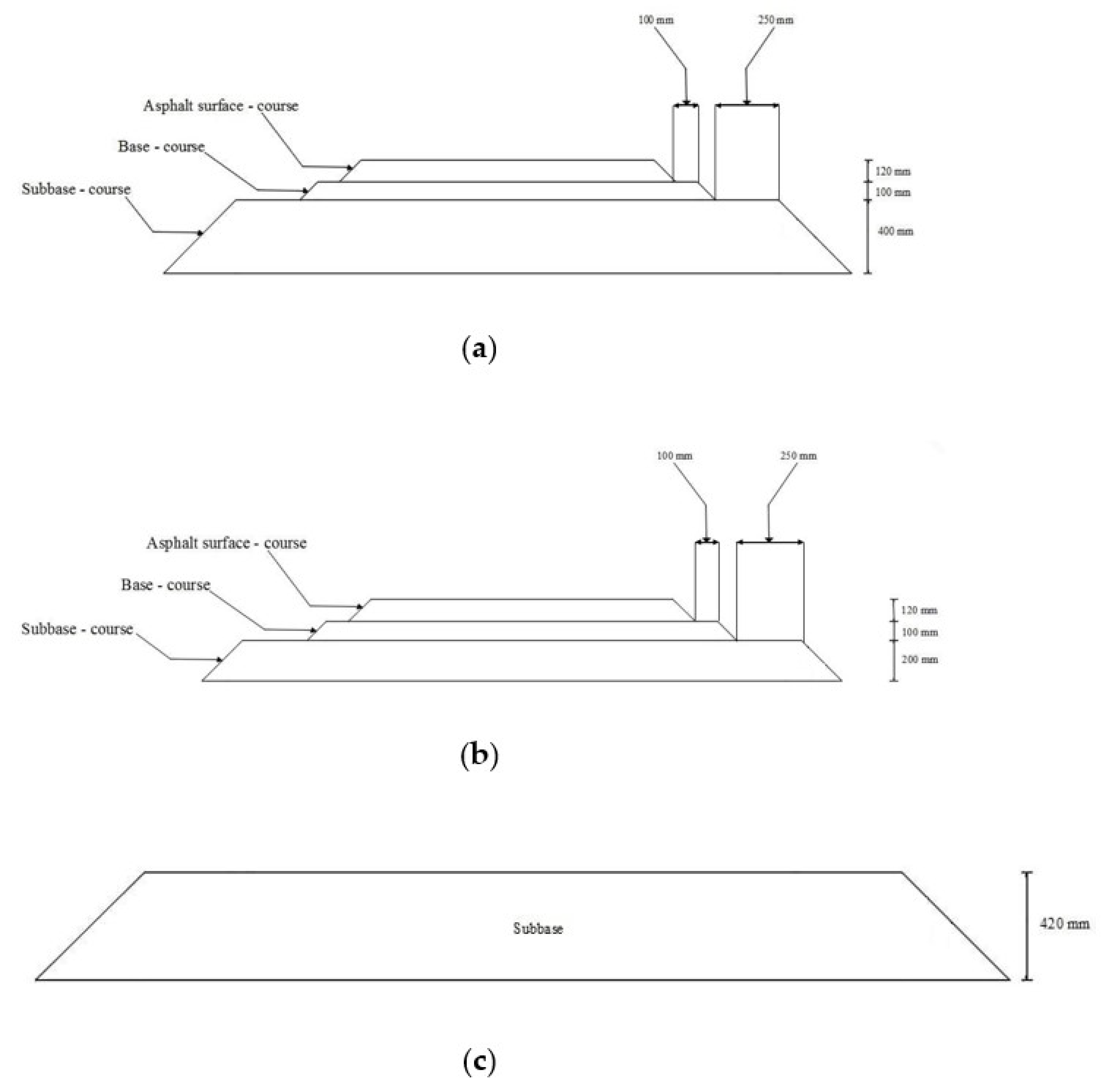
  • Highway section: This road section represents a highway outside the city. The cross section of this road is illustrated in Figure 1a.
  • Public road section: This section represents a public road inside the city, and it is shown in Figure 1b.
  • Unpaved road section: This road section is considered to understand the influence of the surface layer (asphalt surface) on the efficiency of the TDA, and it is shown in Figure 1c.
It is important to state that the angle of inclination of the slope of the embank-ment is equal to 45° for all of the sections. Furthermore, two trench configurations have been considered to clearly examine the TDA efficiency. The first trench configuration involves the use of well-graded sand that is compacted to 90% of the standard Proctor dry density (referred to as SW90 from this point forward) as a backfill soil. This trench configuration is shown in Figure 2a (named CB from this point forward). The second configuration involves the use of SW90 as soil surrounding the pipe with a thin layer of the TDA material with a thickness of 150 mm on top of the pipe crown followed by SW90 soil. This trench configuration is presented in Figure 2b (named TDA from this point forward).

3. Analysis Methodology

3.1. Constituitve Models

The hardening soil model (HSM) is used for modeling the TDA material and the trench soil (SW90). The hardening soil model is a double-stiffness model that models the stress-dependent variation of the soil stiffness due to various conditions of loading [23]. This model is affiliated with the double-stiffness model family. Additionally, the hardening soil model is an extension of the hyperbolic model of Duncan and Chang [24]. The robustness of the HSM in simulating the behavior of the TDA is demonstrated by Mahgoub and El Naggar [19].
The asphalt surface layer has been modeled by the linear elastic model under non-porous conditions, while the Mohr–Coulomb model has been used to model the base, subbase, and natural subgrade. In addition, the Mohr–Coulomb model has been used to simulate the behavior of the interface elements between the soil and the pipe. Furthermore, the behavior of the pipe has been modeled using the linear elastic model, similar to many previous studies, e.g., [12,18,22,25]. This is considered an important step in the methodology, particularly in the pipe design, because the crack development in the concrete pipes is related to the induced bending moment in the pipe wall. Thus, the bending moment is one of the main controlling parameters in the design of buried concrete pipes [26].

3.2. Material Properties

The properties used in the analyses for the SW90 are adopted from those reported by Simpson et al. [23]. This soil is used to fill up the trench (i.e., the soil surrounding the pipe as well as above the TDA layer) in accordance with the AASHTO Type 2 installation conditions for buried concrete pipes [22]. The properties of the TDA, asphalt layer, base, subbase, and subgrade have been adopted from different references [20,27,28,29,30]. Table 1 summarizes the values of these properties. It is important to mention that the material properties of the TDA used in this study have been calibrated by Mahgoub and El Naggar [19], and this TDA is created by fine aggregate with shredded tires and has a particle diameter range of 13 mm to 63 mm [19]. In addition, the TDA used in this research is classified as Type A TDA in accordance with ASTM D6270-08 [9] as stated by Mahgoub [31]. Furthermore, the unit weight, modulus of elasticity, and Poisson’s ratio of the concrete have been set equal to 24 kN/m3, 24,000 MPa, and 0.2, respectively, in accordance with many previous studies, e.g., [12,18,22,25].

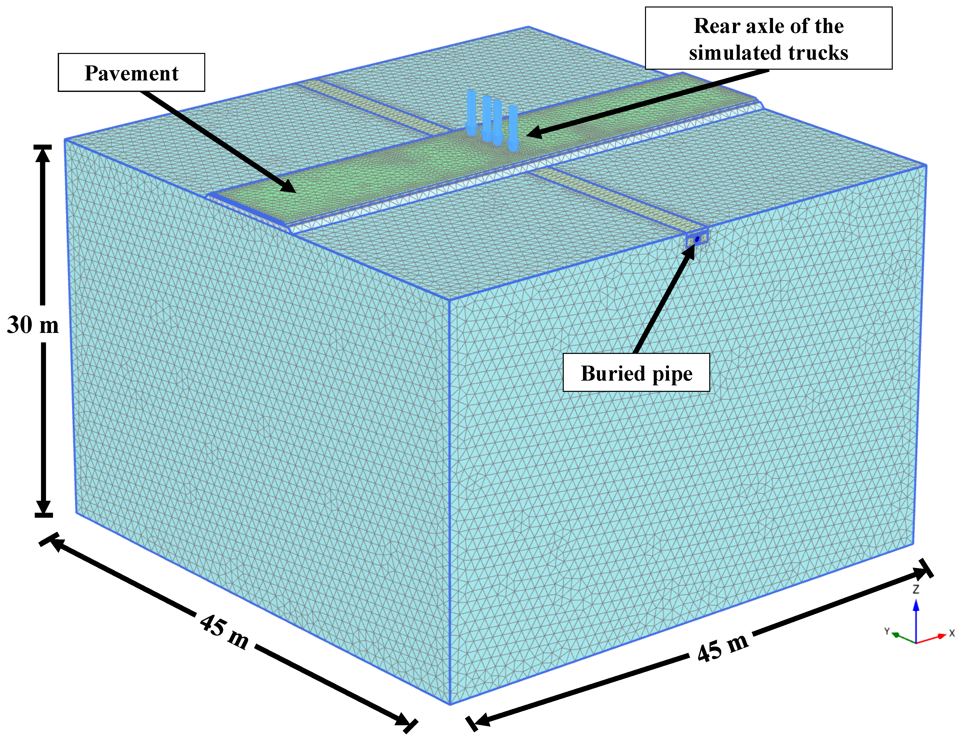
3.3. Development of Finite Element Model

The three-dimensional finite element analyses have been carried out using PLAXIS 3D [32]. The 10-noded tetrahedron elements have been used to model the subgrade, the surface layer, the base, the subbase, and the backfill material (i.e., SW90 and TDA). In addition, the utilized finite element model has a length, width, and depth of 45 m, 45 m, and 30 m, respectively. The length and width of the model have been determined based on a sensitivity analysis. In addition, the depth of the model has been considered equal to 30 m, since it was assumed that the rock layer was laid down to about 30 m below the model’s surface.
Standard boundary conditions have been used, where the model has been fixed at the base and the sides of the model have been assigned to be free only in the vertical direction and fixed in the other horizontal directions. Many studies that used three-dimensional finite element analysis to model soil–structure interaction problems used these boundary conditions as well [33,34,35,36,37,38,39].
Interface elements have been created around the pipe to simulate the soil–structure interaction with a reduction factor ( R i n t ) of 0.7 [6]. Plaxis uses the reduction factor ( R i n t ) and the surrounding soil properties to calculate the properties of the interface elements, using the following equations [40]:
c i = R i n t × c
tan ø i = R i n t × tan ø
G i = R i n t 2 × G
where, c i is the cohesion of the interface element, c is the cohesion of the surrounding soil, ø i is the angle of internal friction of the interface element, ø is the angle of internal friction of the surrounding soil, G i is the shear modulus of the interface element, and G is the shear modulus of the surrounding soil.
The bedding thickness was considered to be equal to 100 mm [41]. To represent traffic loading, the rear axles of two H25 trucks were used in the analyses. To account for critical loading conditions, the trucks were assumed to travel perpendicular to the pipe, with the rear axle on top of the pipe [42,43]. The tire load is assumed to be stationary because static traffic loads produce higher deformation in the pipe compared to moving loads [44,45,46]. In addition, very fine mesh density has been used based upon a sensitivity analysis of the mesh accuracy. The mesh as well as the geometry of the developed model are shown in Figure 3.
Furthermore, the analyses have been carried out in stages to enable a realistic simulation, as follows:
  • The first stage involved determining the at-rest soil stresses.
  • The second stage involved the modeling of the trench excavation.
  • The third stage entailed modeling the layout of the buried pipe.
  • The fourth stage involved the modeling of the re-filling of the trench.
  • The fifth stage involved the laying out of all road layers.
  • The sixth stage entailed loading the truck’s rear axle.
Finally, it is important to mention that the methodology of the finite element analysis that was followed throughout this study was validated against full-scale test results, and the validated model and its results can be found in another publication published by the authors [6].

4. Results

The effect of the road section and burial depth on the efficiency of TDA in reducing the bending moment induced in the wall of a buried concrete pipe is examined in these subsections:

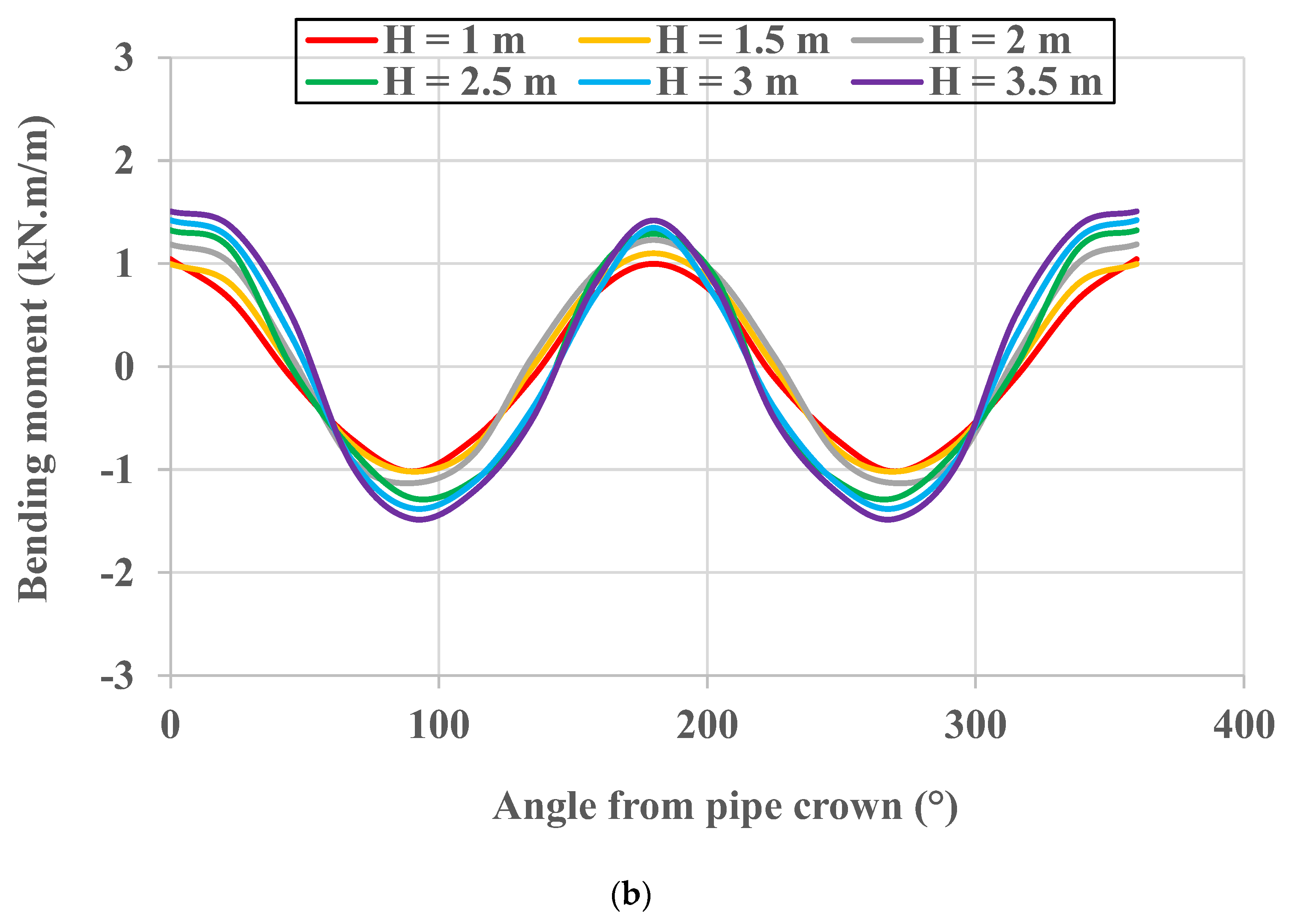
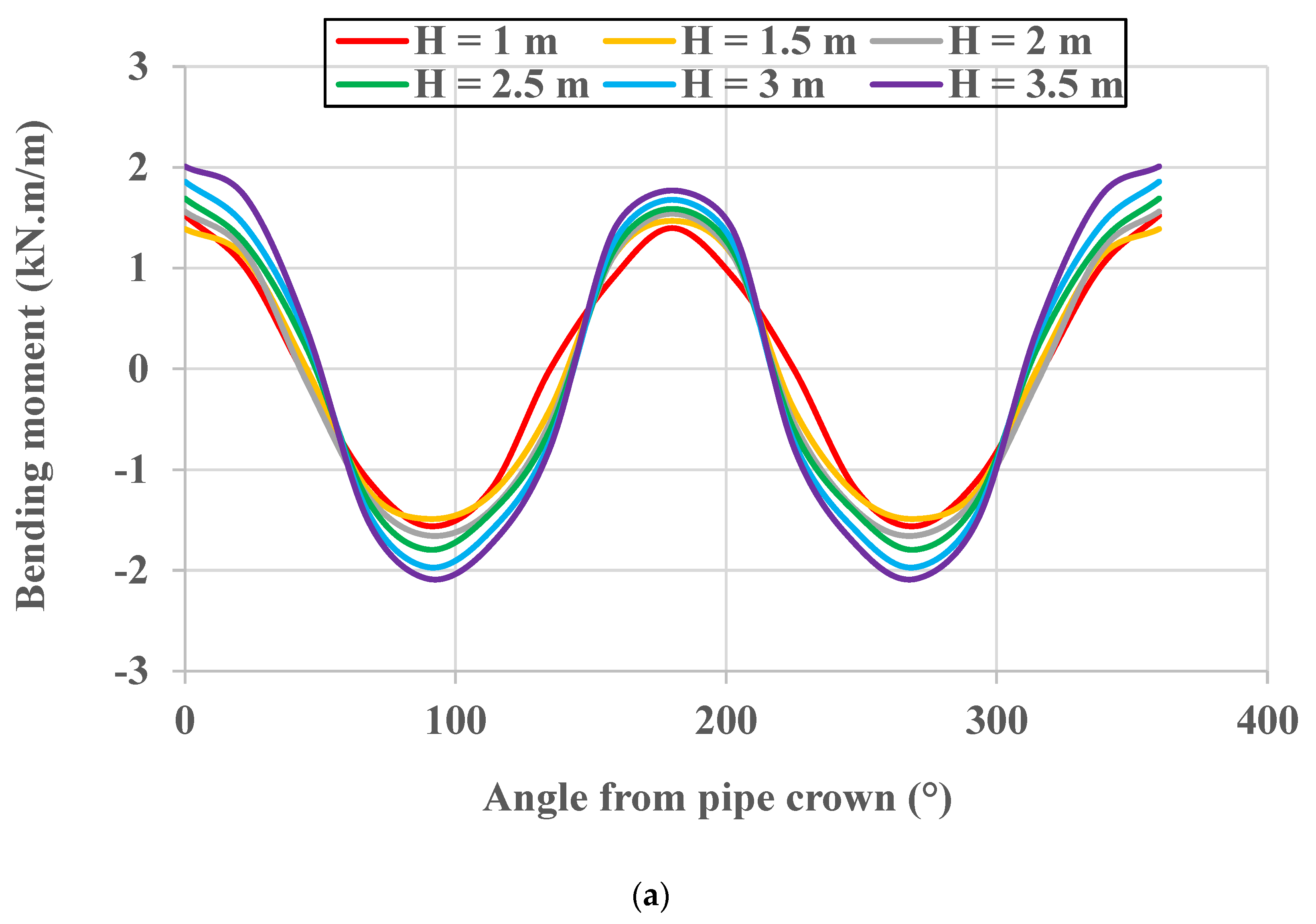
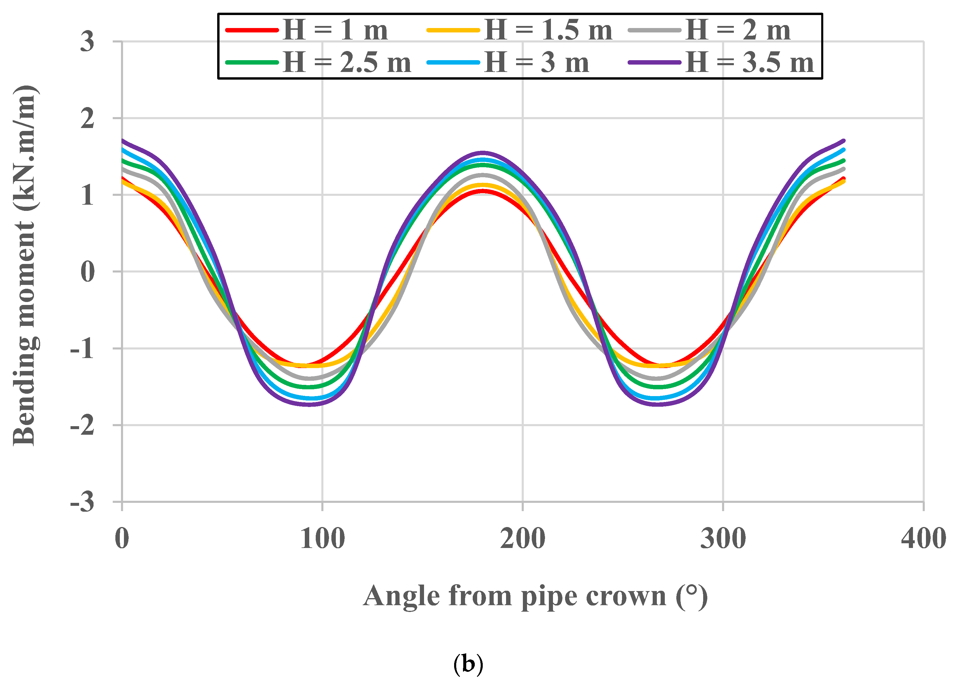
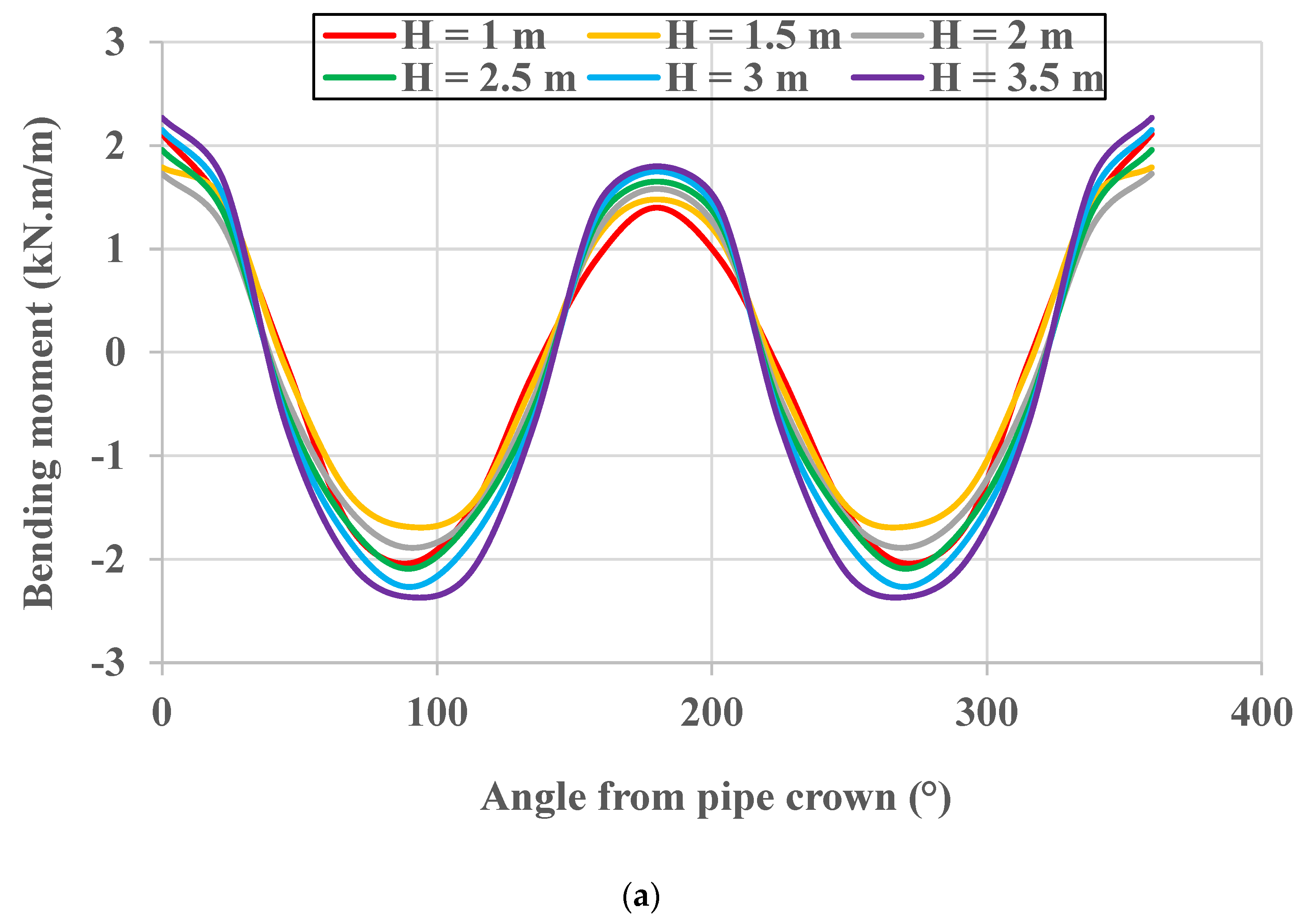
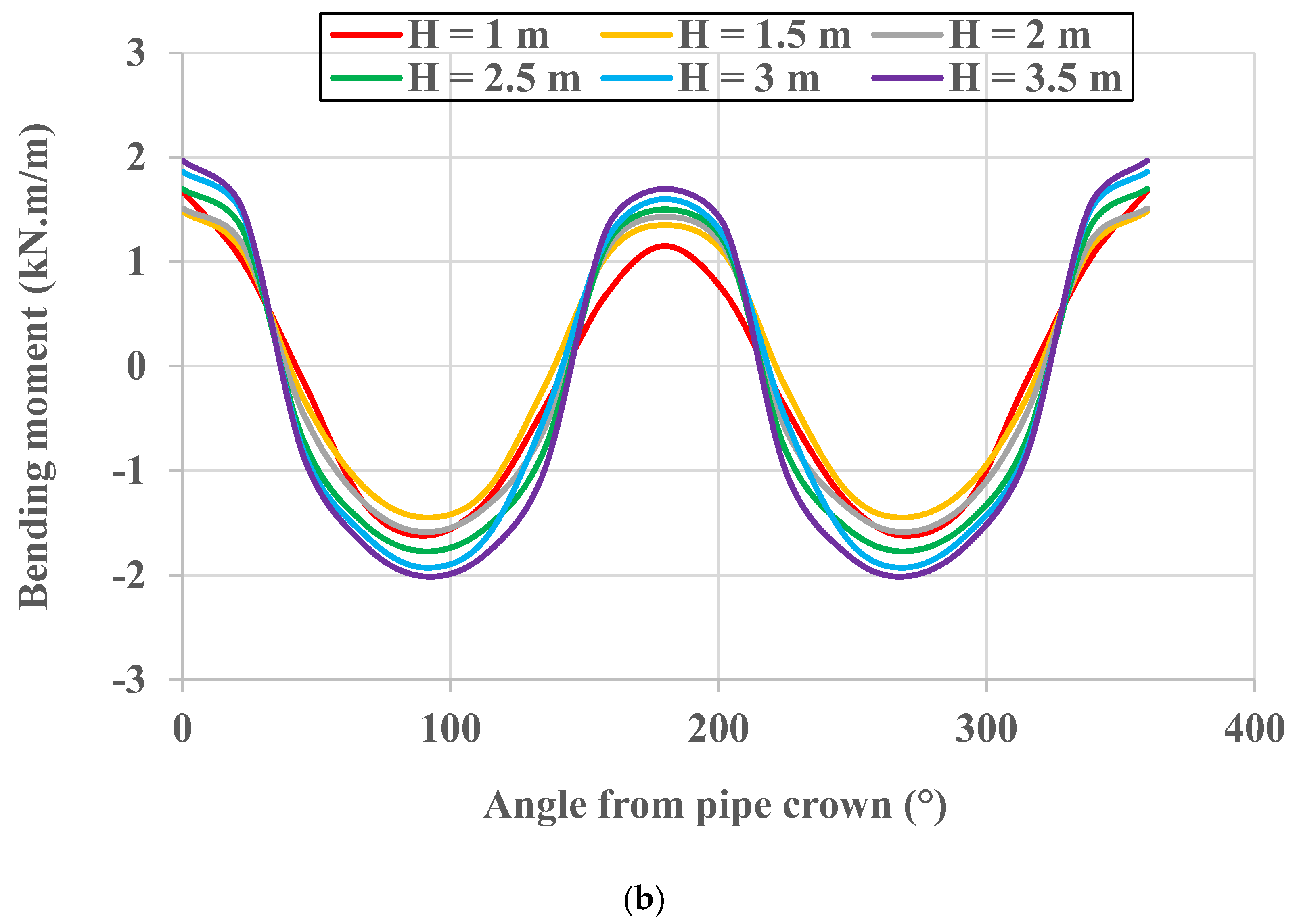
4.1. The Influence of TDA on the Induced Pipe Wall Bending Moment Distribution

The distribution of the induced bending moment in the pipe wall is checked for both cases (CB and TDA) and for the burial depth (H) range from 1.0 m to 3.5 m. Figure 4, Figure 5 and Figure 6 present the induced bending moment in the pipe wall for highway, public road, and unpaved road, respectively, and for both CB and TDA configurations. It is clear from the presented figures that the induced bending moment in the pipe wall decreased due to the presence of TDA. However, the trend of the relationship between the angle from the pipe crown and the induced bending moment is not affected. This is because the TDA uniformly reduced the soil pressure applied on top of the pipe in a symmetrical way as it was applied to the whole pipe (refer to Figure 2b). Furthermore, it can be noticed by comparing the results for different road sections that the unpaved road section gives the maximum bending moment compared to other road sections. This behavior is due to the absence of the asphalt surface layer for the unpaved section; this contributes to reducing the effect of the traffic loads on the other layer of the road, and hence, the buried pipe. In addition, it is also clear that the bending moment induced in the pipe wall, in the case of the public road, is noticeably higher than that of the highway. This behavior is due to the fact that the total thickness of the compacted layers for the highway is higher than that of the public road section, and these compacted layers help in reducing the induced soil pressures that reach the top of the pipe due to the effect of the traffic loads.

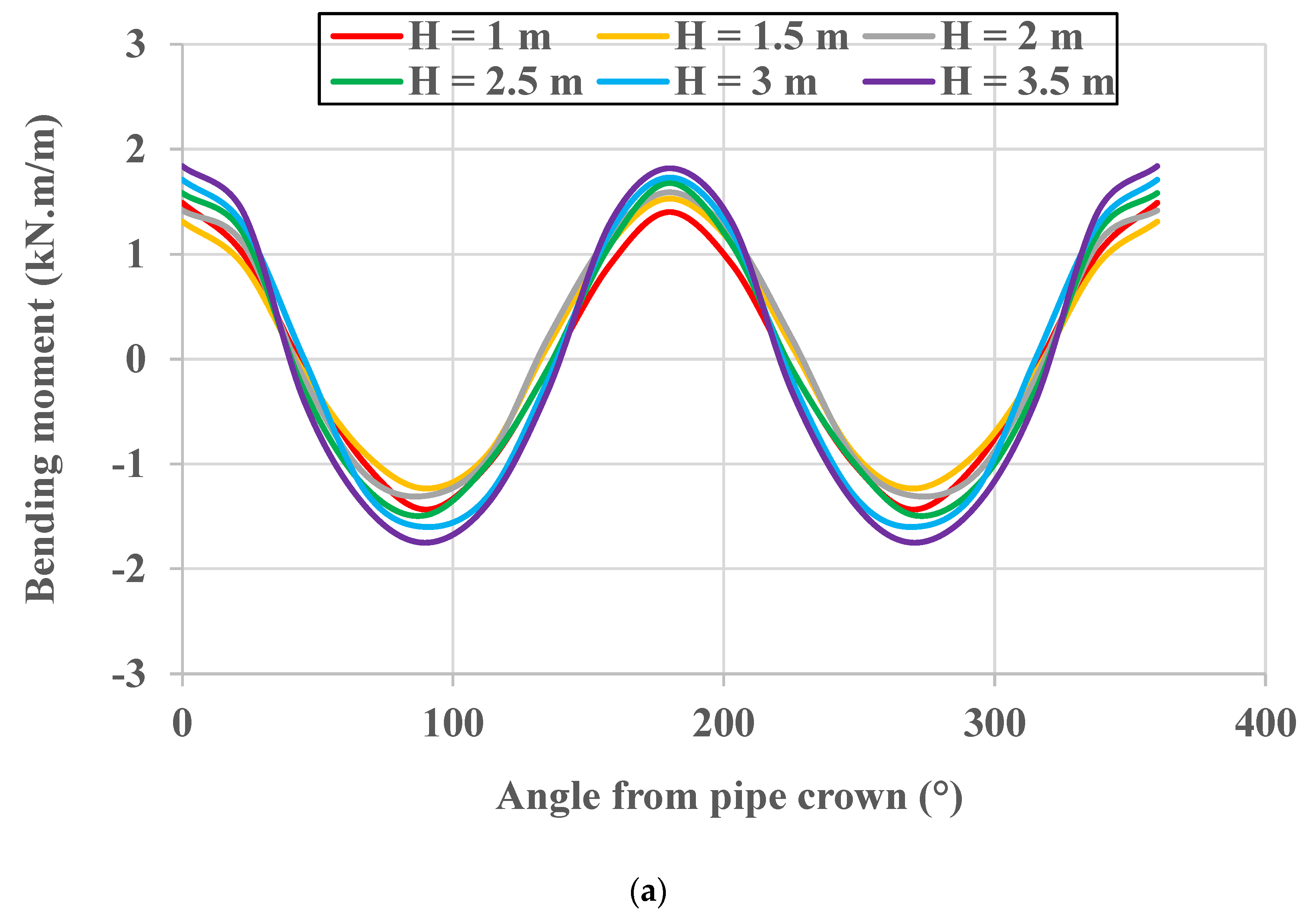
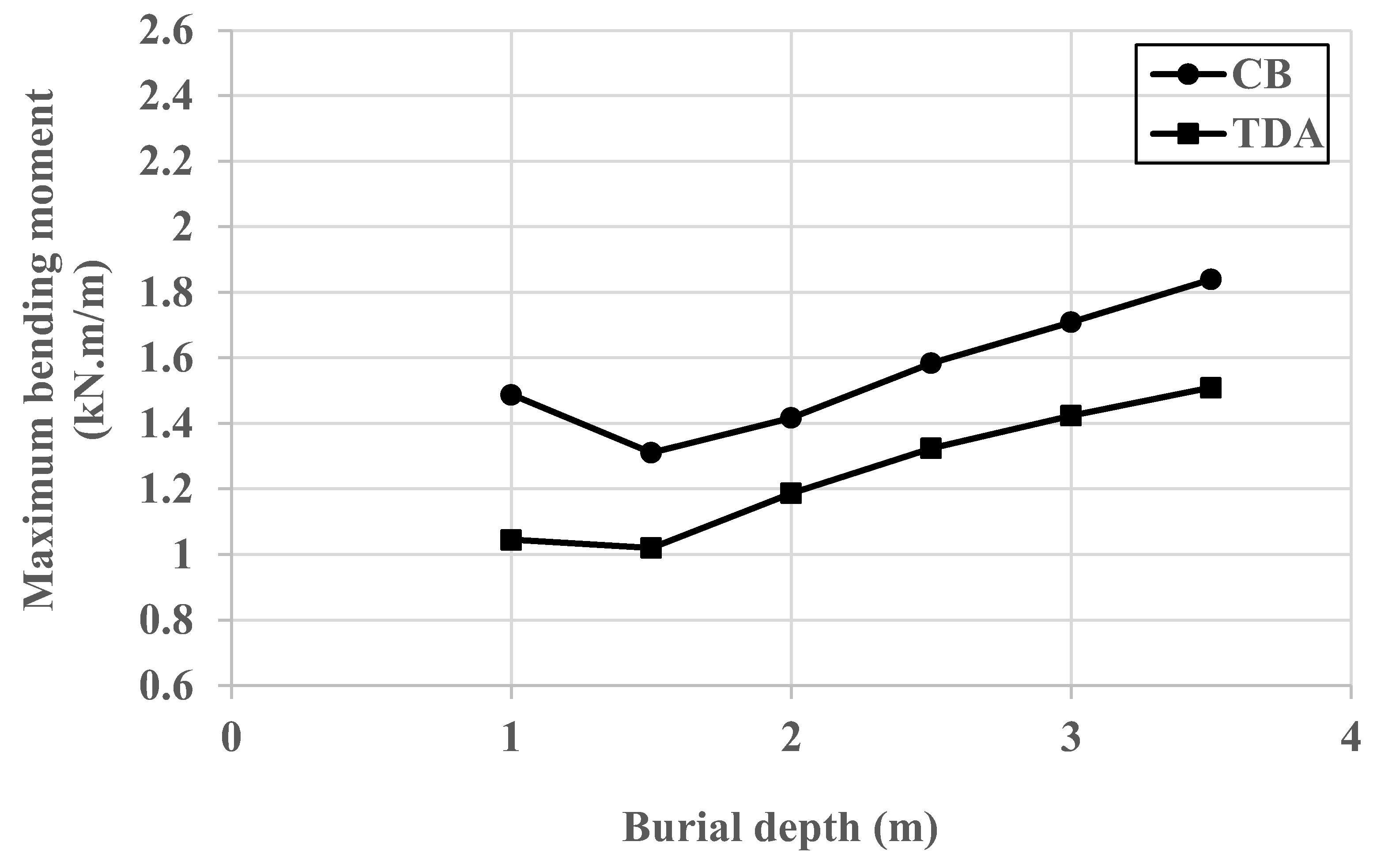
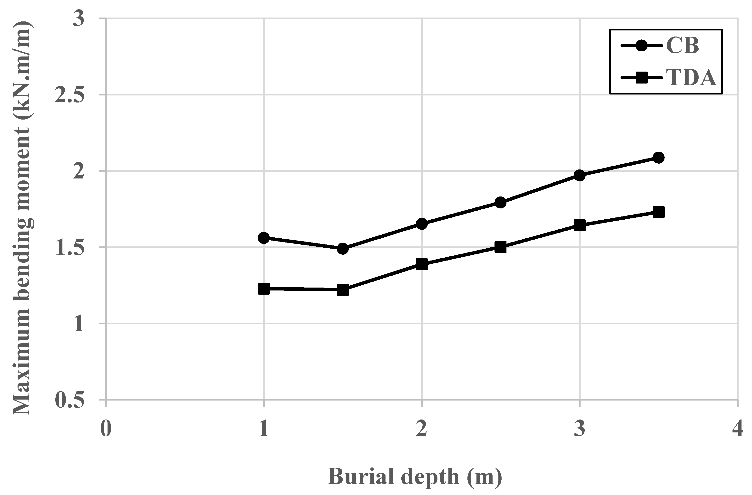
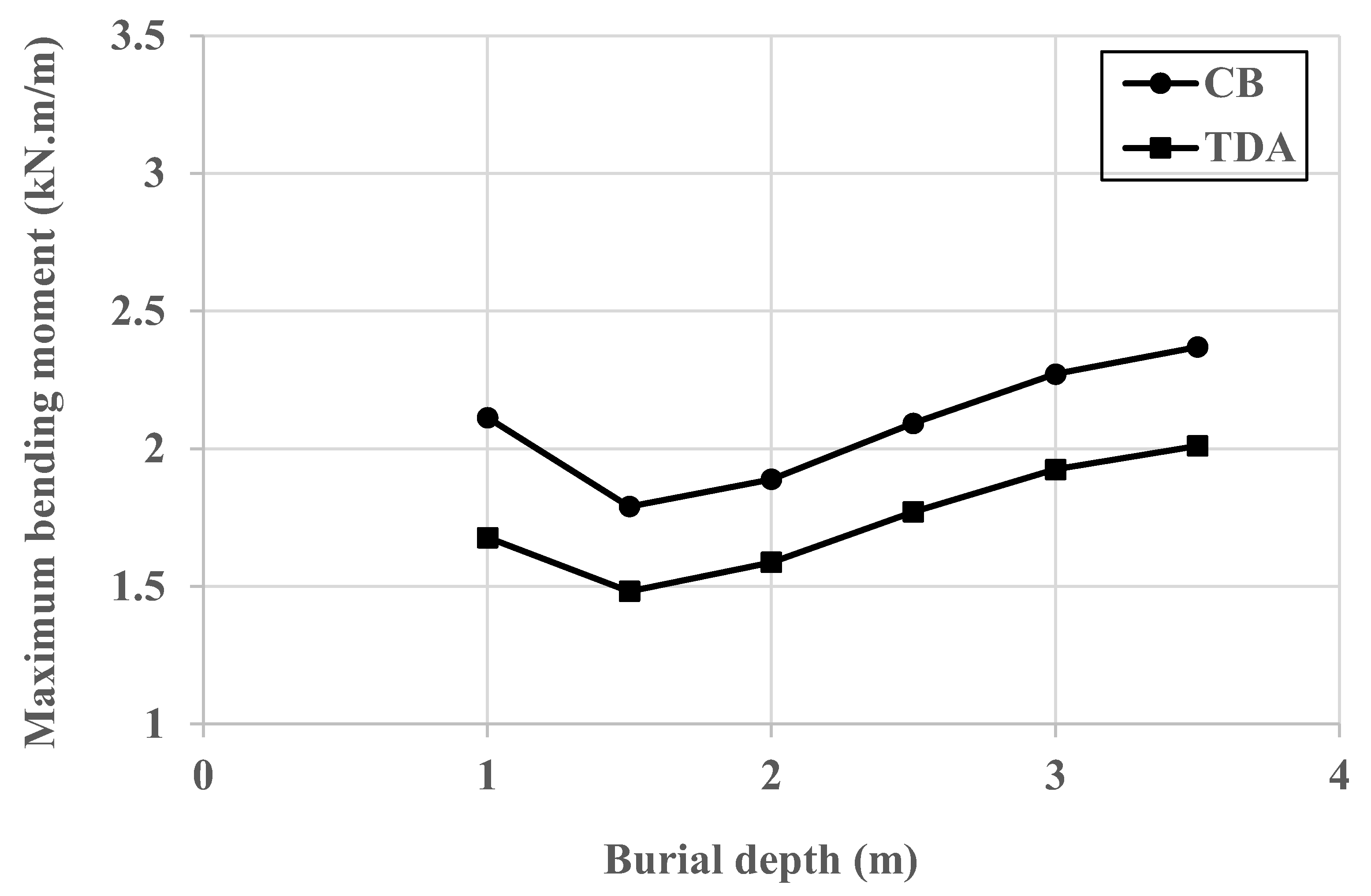
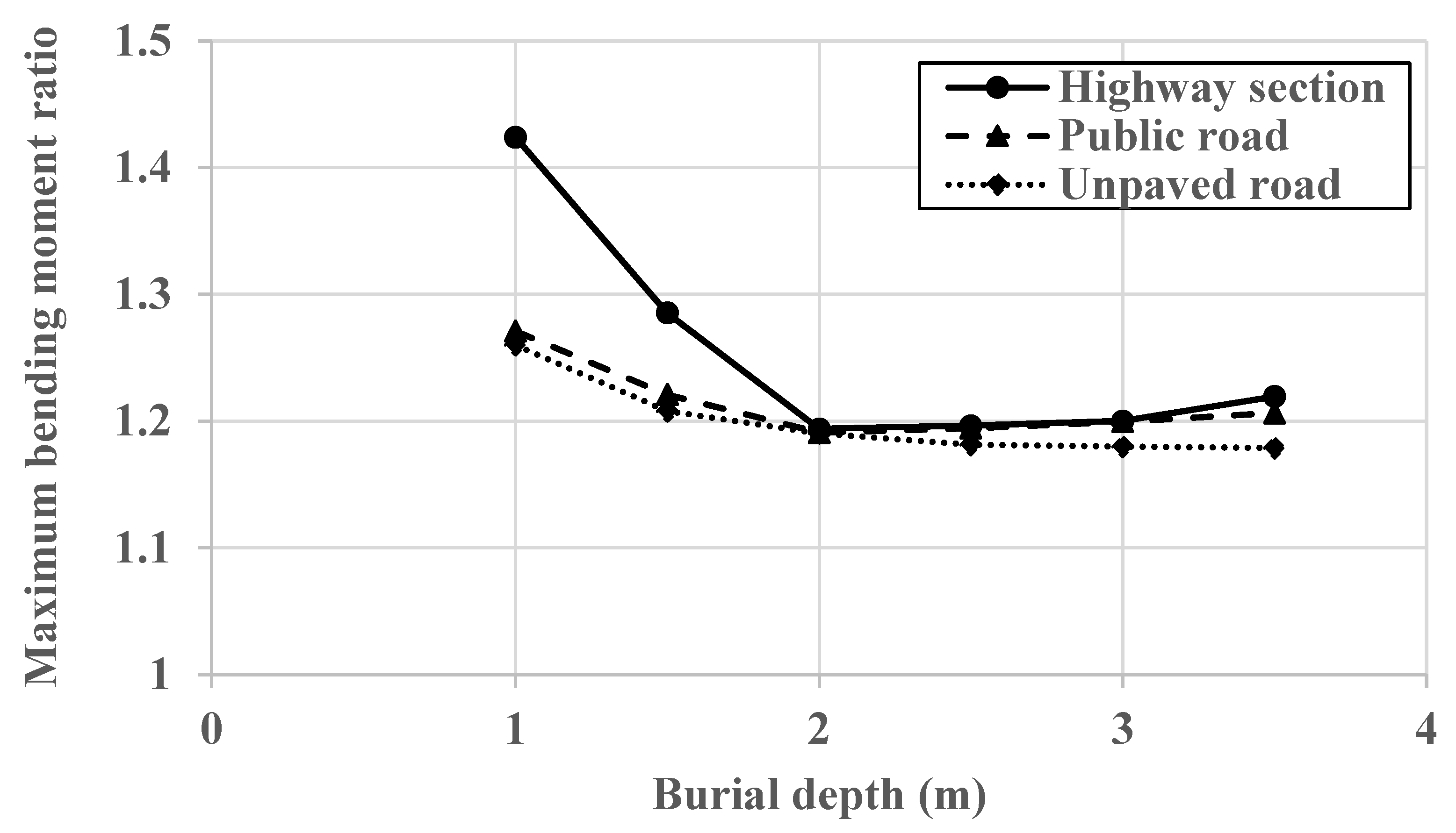
4.2. The Influence of Burial Depth on TDA Efficiency

Figure 7, Figure 8 and Figure 9 depict the relationship between the maximum bending moment and burial depth for the CB and TDA configurations for highway, public, and unpaved road sections, respectively. It is obvious from the figures that the maximum bending moment for the CB configuration is reduced when the burial depth rises from 1.0 m to 1.5 m for all road sections. Thereafter, the maximum bending moment rises as the burial depth increases for all road sections. This behavior is due to the complicated interaction caused by the reduction of the effect of the traffic loads and the increase in the soil weight at the same time as the burial depth increases [6,47]. Furthermore, the trend of the relationship between the maximum bending moment and the burial depth is similar for the CB and TDA configurations, which is again due to the TDA uniformly reducing the soil pressure applied on top of the pipe in a symmetrical way as it was applied to the whole pipe. However, it is also clear that the TDA reduced the maximum bending moment induced in the pipe wall, which is due to the positive soil arching.
Figure 10 show the relationship between the burial depth and the ratio of the maximum bending moment of the CB to TDA configurations for the highway, public road, and unpaved road. These figures aim to show the percentage decrease in the maximum bending moment due to the use of the TDA. It can be noticed from the figures that the bending moment ratio reduces as the burial depth increases for all road types. This indicates that the TDA’s effectiveness in decreasing the pipe-bending moment decreases as the burial depth increases. This also indicates that the positive soil arching also decreases as the burial depth increases. Furthermore, it can be seen from the figures that the change in the bending moment ratio becomes almost unnoticeable for all road sections with a burial depth equal to or greater than 2.0 m. This behavior means that the positive arching factor almost stabilizes for burial depths equal to or greater than 2.0 m.
In summary, the figures show that the best efficiency of the TDA is recorded for a burial depth of 1.0 m, as the highest decrease in the maximum bending moment is recorded at this burial depth, where the percent decrease in the maximum bending moment at 1 m depth is equal to 42% for the highway section, 27% for the public road, and 26% for the unpaved road. These calculated ratios also mean that the TDA performs better in the case of the highway section compared to the other road sections.

5. Conclusions

This paper presented the results of validated three-dimensional finite element analyses that have been performed to evaluate the efficiency of the TDA material in reducing the bending moment induced in the wall of a buried concrete pipe under the influence of the backfill soil weight and traffic loads. In this respect, two trench configurations have been analyzed, the first one involved the use of a compacted, well-graded coarse-grained soil as a backfill material in accordance with the AASHTO Type 2 installation requirements, and the second one involved the use of a 150 mm TDA layer on top of the pipe crown. Furthermore, three road sections have been adopted to provide an understanding of TDA efficiency under various road conditions. These road sections are the highway section, the public road section, and the unpaved road section. The following conclusions can be stated based upon the findings from this study:
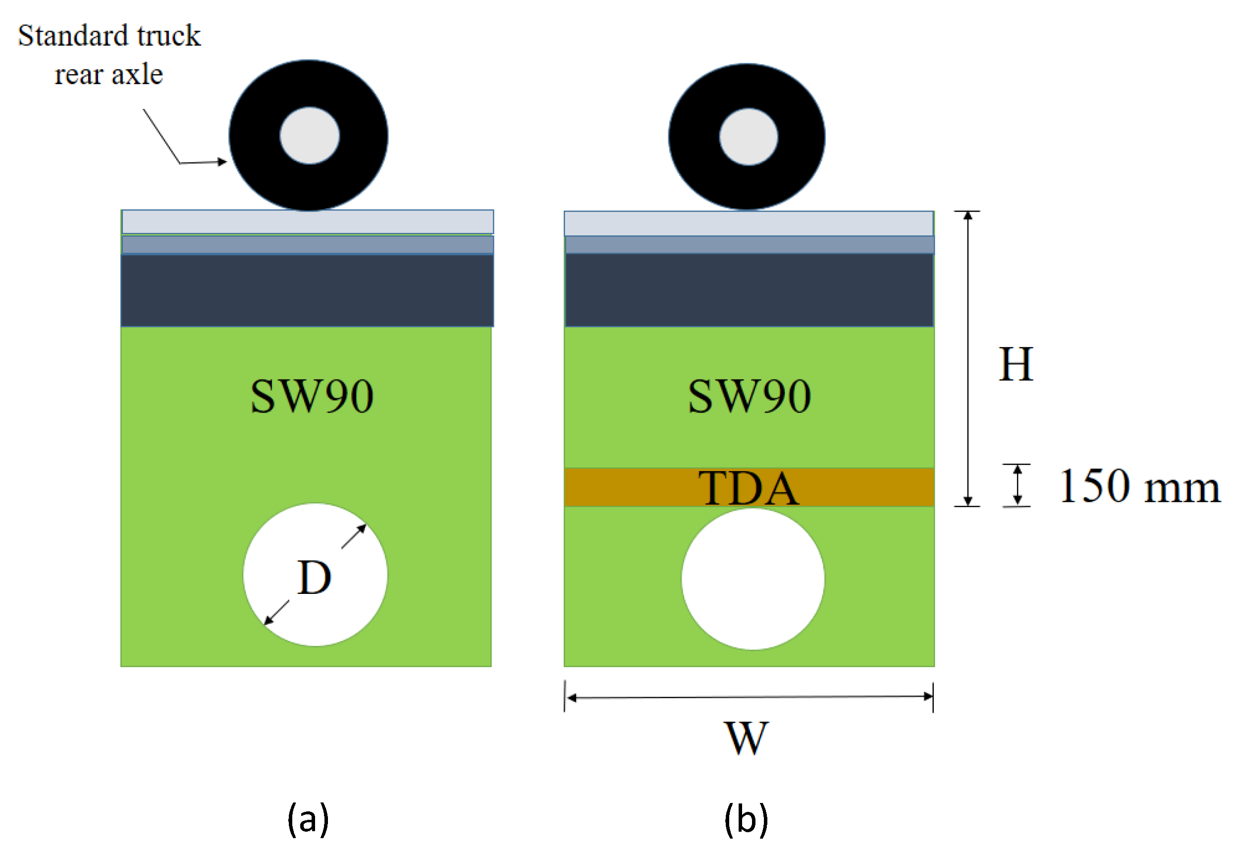
  • The finite element analyses showed that the use of a TDA layer above the pipe crown assisted in decreasing the induced pipe wall bending moment in comparison to the use of conventional compacted well-graded backfill only. However, the TDA did not influence the distribution of the induced bending moment around the pipe.
  • The highest decrease in bending moment values that resulted from the existence of the TDA layer occurred at a 1 m burial depth, where the percent decrease in the bending moment at a 1 m burial depth was 42% for the highway, 27% for the public road section, and 26% for the unpaved road.
  • The TDA’s effectiveness in decreasing the pipe-bending moment decreases as the burial depth increases. This behavior is justified by the decrease in positive soil arching with the increase in burial depth. In addition, the percentage decrease in the maximum bending moment is found to become constant after a particular burial depth, which means that the positive soil arching becomes almost constant after a certain burial depth, depending on the road type.

Author Contributions

Conceptualization, S.A. and S.K.; methodology, S.A. and S.M.A.; software, S.A. and S.M.A.; validation, S.M.A.; formal analysis, S.M.A.; investigation, S.A. and S.K.; resources, S.K.; data curation, S.M.A.; writing—original draft preparation, S.A. and S.K.; writing—review and editing, S.K.; visualization, S.A. and S.M.A.; supervision, S.A.; project administration, S.A.; funding acquisition, S.K. All authors have read and agreed to the published version of the manuscript.

Funding

This research received no external funding.

Institutional Review Board Statement

Not applicable.

Informed Consent Statement

Not applicable.

Data Availability Statement

Not applicable.

Conflicts of Interest

The authors declare no conflict of interest.

References

  1. Arulrajah, A.; Piratheepan, J.; Disfani, M.M.; Bo, M.W. Geotechnical and geoenvironmental properties of recycled construction and demolition materials in pavement subbase applications. J. Mater. Civ. Eng. 2013, 25, 1077–1088. [Google Scholar] [CrossRef]
  2. Mujtaba, H.; Khalid, U.; ur Rehman, Z.; Farooq, K. Recycling of reclaimed subbase materials in flexible pavement design. Road Mater. Pavement Des. 2022, 23, 2713–2732. [Google Scholar] [CrossRef]
  3. Purohit, S.; Panda, M.; Chattaraj, U. Use of reclaimed asphalt pavement and recycled concrete aggregate for bituminous paving mixes: A simple approach. J. Mater. Civ. Eng. 2021, 33, 04020395. [Google Scholar] [CrossRef]
  4. Rehman, U.Z.; Khalid, U. Reuse of COVID-19 face mask for the amelioration of mechanical properties of fat clay: A novel solution to an emerging waste problem. Sci. Total Environ. 2021, 794, 148746. [Google Scholar] [CrossRef] [PubMed]
  5. Plati, C.; Tsakoumaki, M.; Gkyrtis, K. Physical and Mechanical Properties of Reclaimed Asphalt Pavement (RAP) Incorporated into Unbound Pavement Layers. Appl. Sci. 2022, 13, 362. [Google Scholar] [CrossRef]
  6. Alqahtani, F.K.; Khan, M.I.; Ghataora, G.; Dirar, S. Production of recycled plastic aggregates and its utilization in concrete. J. Mater. Civ. Eng. 2017, 29, 04016248. [Google Scholar] [CrossRef] [Green Version]
  7. Alqahtani, F.K.; Zafar, I. Exploring the Effect of Different Waste Fillers in Manufactured Sustainable Plastic Aggregates Matrix on the Structural Lightweight Green Concrete. Sustainability 2023, 15, 2311. [Google Scholar] [CrossRef]
  8. Rubber Manufacturers Association. US Scrap Tire Management Summary 2005–2009; Rubber Manufacturers Association: Washington, DC, USA, 2011. [Google Scholar]
  9. ASTM D 6270-98; Standard Practice for Use of Scrap Tires in Civil Engineering Applications. ASTM: West Conshohocken, PA, USA, 2008.
  10. Adhikari, B.; De, D.; Maiti, S. Reclamation and recycling of waste rubber. Prog. Polym. Sci. 2000, 25, 909–948. [Google Scholar] [CrossRef]
  11. Tafreshi, S.M.; Mehrjardi, G.T.; Dawson, A.R. Buried pipes in rubber-soil backfilled trenches under cyclic loading. J. Geotech. Geoenviron. Eng. 2012, 138, 1346–1356. [Google Scholar] [CrossRef] [Green Version]
  12. Alzabeebee, S.; Alshibany, S.M.; Keawsawasvong, S. Influence of Using Tire-Derived Aggregate on the Structural Performance of Buried Concrete Pipe under Embankment Load. Geotechnics 2022, 2, 989–1002. [Google Scholar] [CrossRef]
  13. McGuigan, B.L.; Valsangkar, A.J. Earth pressures on twin positive projecting and induced trench box culverts under high embankments. Can. Geotech. J. 2011, 48, 173–185. [Google Scholar] [CrossRef]
  14. Turan, A.; El Naggar, M.H.; Dundas, D. Investigation of induced trench method using a full scale test embankment. Geotech. Geolo. Eng. 2013, 31, 557–568. [Google Scholar] [CrossRef]
  15. Qin, X.; Wang, Y. Reliability-based design of rigid pipes installed by induced trench method with tire-derived aggregate inclusions. Comput. Geotech. 2021, 140, 104456. [Google Scholar] [CrossRef]
  16. Bryden, C.; Arjomandi, K.; Valsangkar, A. Distribution of Earth Pressure on Induced Trench Culverts. Int. J. Geomech. 2022, 22, 04022072. [Google Scholar] [CrossRef]
  17. Meguid, M.A.; Youssef, T.A. Experimental investigation of the earth pressure distribution on buried pipes backfilled with tire-derived aggregate. Transport. Geotech. 2018, 14, 117–125. [Google Scholar] [CrossRef]
  18. Ni, P.; Qin, X.; Yi, Y. Numerical study of earth pressures on rigid pipes with tire-derived aggregate inclusions. Geosynth. Int. 2018, 25, 494–506. [Google Scholar] [CrossRef]
  19. Mahgoub, A.; El Naggar, H. Using TDA as an engineered stress-reduction fill over preexisting buried pipes. J. Pipeline Syst. Eng. Pract. 2019, 10, 04018034. [Google Scholar] [CrossRef]
  20. Mahgoub, A.; El Naggar, H. Innovative application of tire-derived aggregate around corrugated steel plate culverts. J. Pipeline Syst. Eng. Pract. 2020, 11, 04020025. [Google Scholar] [CrossRef]
  21. Alzabeebee, S. Tire Derived Aggregate as a Sustainable Technique to Mitigate Transient Seismic Effect on Buried Concrete Pipes. In Sustainable Cities and Resilience; Springer: Singapore, 2022; pp. 317–328. [Google Scholar] [CrossRef]
  22. Alzabeebee, S.; Chapman, D.N.; Faramarzi, A. Development of a novel model to estimate bedding factors to ensure the economic and robust design of rigid pipes under soil loads. Tunn. Undergr. Space Technol. 2018, 71, 567–578. [Google Scholar] [CrossRef] [Green Version]
  23. Schanz, T.; Vermeer, P.A.; Bonnier, B.G. The hardening soil model: Formulation and verification. In Beyond 2000 in Computational Geotechnics—10 Years of PLAXIS; Brinkgreve, R.B.J., Ed.; Routledge: London, UK, 1999; pp. 1–16. [Google Scholar]
  24. Duncan, J.M.; Chang, C.Y. Nonlinear analysis of stress and strain in soils. J. Soil Mech. Found. Div. 1970, 96, 1629–1653. [Google Scholar] [CrossRef]
  25. Alzabeebee, S.; Chapman, D.N.; Faramarzi, A. Economical design of buried concrete pipes subjected to UK standard traffic loading. Proc. Inst. Civ. Eng. Struct. Build. 2019, 172, 141–156. [Google Scholar] [CrossRef]
  26. Tan, Z.; Moore, I.D. Effect of backfill erosion on moments in buried rigid pipes. In Proceedings of the Transportation Research Board 86th Annual Meeting, Washington, DC, USA, 21–25 January 2007; 29p. [Google Scholar]
  27. Simpson, Gumpertz, Heger. Appendix an Investigation of Suitable Soil Constitutive Models for 3-D Finite Element Studies of Live Load Distribution through Fills onto Culverts; National Cooperative Highway Research Program Project: McLean, VA, USA, 2009.
  28. Thompson, M.R.; Elliott, R.P. ILLI-PAVE based response algorithms for design of conventional flexible pavements. Transport. Res. Rec. 1985, 1043, 50–57. [Google Scholar]
  29. Huang, Y.H. Pavement Analysis and Design; Pearson Prentice Hall: Upper Saddle River, NJ, USA, 2004. [Google Scholar]
  30. Bowers, J.T.; Webb, M.C.; Beaver, J.L. Soil Parameters for Design with the 3D PLAXIS Hardening Soil Model. Transport. Res. Rec. 2019, 2673, 708–713. [Google Scholar] [CrossRef]
  31. Mahgoub, A. Innovative Applications of Tire Derived Aggregate (TDA) for Buried Pipes and Culverts. Ph.D. Thesis, Dalhousie University, Halifax, NS, Canada, September 2020. [Google Scholar]
  32. PLAXIS 3D CONNECT Edition V20, Bentley Systems, Incorporated. 2020. Available online: https://communities.bentley.com/products/geotech-analysis/w/wiki/50242/plaxis-3d-ce-v20-03-00-release-notes (accessed on 5 October 2022).
  33. Hasan, S.A. Analysis of pile-raft foundations for Burj Al-Amir in a Najaf City. Al-Qadisiyah J. Eng. Sci. 2013, 6, 148–164. [Google Scholar]
  34. Trickey, S.A.; Moore, I.D.; Balkaya, M. Parametric study of frost-induced bending moments in buried cast iron water pipes. Tunn. Undergr. Space Technol. 2016, 51, 291–300. [Google Scholar] [CrossRef]
  35. Mandeel, S.A.H.; Fadhil, A.; Mekkiyah, H.M. Bearing capacity of square footing resting on layered soil. Al-Qadisiyah J. Eng. Sci. 2020, 13, 306–313. [Google Scholar] [CrossRef]
  36. Patra, S.; Bera, A.K. Development of Design Chart for Jute Geotextiles Reinforced Low Volume Road Section by Finite Element Analysis. Transp. Infrastruct. Geotech. 2021, 8, 88–113. [Google Scholar] [CrossRef]
  37. Li, Y.; Zhang, W.; Zhang, R. Numerical investigation on performance of braced excavation considering soil stress-induced anisotropy. Acta Geotech. 2022, 17, 563–575. [Google Scholar] [CrossRef]
  38. Pradhan, B.; Tiwari, S.K. FEM Analysis of Granular Pile Made with Alternate Materials. Transp. Infrastruct. Geotech. 2022. [Google Scholar] [CrossRef]
  39. Mohamed, M.K.; Sakr, M.A.; Azzam, W.R. Geotechnical behavior of encased stone columns in soft clay soil. Innov. Infrastruct. Solut. 2023, 8, 80. [Google Scholar] [CrossRef]
  40. Fatahi, B.; Huang, B.; Yeganeh, N.; Terzaghi, S.; Banerjee, S. Three-dimensional simulation of seismic slope–foundation–structure interaction for buildings near shallow slopes. Int. J. Geomech. 2020, 20, 04019140. [Google Scholar] [CrossRef]
  41. Howard, A.K. Pipe Bedding and Backfill, 2nd ed.; Earth Sciences Laboratory, Geotechnical Services Team, Technical Service Center, Bureau of Reclamation: Denver, CO, USA, 1996. [Google Scholar]
  42. Kang, J.; Stuart, S.J.; Davidson, J.S. Analytical study of minimum cover required for thermoplastic pipes used in highway construction. Struct. Infrastruct. Eng. 2014, 10, 316–327. [Google Scholar] [CrossRef]
  43. Alzabeebee, S.; Chapman, D.; Jefferson, I.; Faramarzi, A. The response of buried pipes to UK standard traffic loading. Proc. Inst. Civ. Eng. Geotech. Eng. 2017, 170, 38–50. [Google Scholar] [CrossRef] [Green Version]
  44. Alzabeebee, S.; Chapman, D.N.; Faramarzi, A. A comparative study of the response of buried pipes under static and moving loads. Transport. Geotech. 2018, 15, 39–46. [Google Scholar] [CrossRef]
  45. Yeau, K.Y.; Sezen, H.; Fox, P.J. Load performance of in situ corrugated steel highway culverts. J. Perform. Constr. Facil. 2009, 23, 32–39. [Google Scholar] [CrossRef]
  46. Sheldon, T.; Sezen, H.; Moore, I.D. Joint response of existing pipe culverts under surface live loads. J. Perform. Constr. Facil. 2015, 29, 04014037. [Google Scholar] [CrossRef]
  47. Alzabeebee, S.; Chapman, D.N.; Faramarzi, A. Innovative approach to determine the minimum wall thickness of flexible buried pipes. Geomech. Eng. 2018, 15, 755–767. [Google Scholar] [CrossRef]
Figure 1. The details of the roads adopted in this research: (a) highway section, (b) public road, and (c) unpaved road.
Geotechnics 03 00005 g001
Figure 2. Trench configurations: (a) conventional backfill configuration (CB) and (b) TDA configuration.
Geotechnics 03 00005 g002
Figure 3. An example of the geometry and mesh that were used in this study.
Geotechnics 03 00005 g003
Figure 4. The distribution of bending moments induced in the wall of a buried concrete pipe for the highway and for (a) the CB configuration; (b) the TDA configuration.
Geotechnics 03 00005 g004aGeotechnics 03 00005 g004b
Figure 5. The distribution of bending moments induced in the wall of a buried concrete pipe for the public road and for (a) the CB configuration; (b) the TDA configuration.
Geotechnics 03 00005 g005aGeotechnics 03 00005 g005b
Figure 6. The distribution of bending moments induced in the wall of a buried concrete pipe for the unpaved road and for (a) the CB configuration; (b) the TDA configuration.
Geotechnics 03 00005 g006aGeotechnics 03 00005 g006b
Figure 7. The relationship between the burial depth and the maximum bending moment for CB and TDA configurations for the highway section.
Geotechnics 03 00005 g007
Figure 8. The relationship between the burial depth and the maximum bending moment for CB and TDA configurations for the public road section.
Geotechnics 03 00005 g008
Figure 9. The relationship between the burial depth and the maximum bending moment for CB and TDA configurations for the unpaved road section.
Geotechnics 03 00005 g009
Figure 10. The influence of the burial depth on the maximum bending moment ratio for all of the road sections.
Geotechnics 03 00005 g010
Table 1. Parameters of all materials that were used in the modeling.
ParameterSW90TDAAsphalt LayerBaseSubbaseSubgrade
Unit weight (kN/m3)20.997.0022.7921.2219.0017.00
Elastic modulus (MPa)--31042149331
Poisson’s ratio--0.350.380.350.30
E50ref (MPa)32.4462.750----
Eoedref (MPa)32.4462.200----
Eurref (MPa)97.3388.250----
υur0.200.20----
Cohesion (kPa)0.0124-0020
Angle of internal friction (˚)45.526.5-50.040.030.0
Dilatancy angle (˚)15.50.0-20.010.00.0
m 0.750.50----
Konc0.310.55----
R f 0.750.95----
Pref (kPa)10025----
Disclaimer/Publisher’s Note: The statements, opinions and data contained in all publications are solely those of the individual author(s) and contributor(s) and not of MDPI and/or the editor(s). MDPI and/or the editor(s) disclaim responsibility for any injury to people or property resulting from any ideas, methods, instructions or products referred to in the content.

