Article

A Hybrid Triboelectric-Electromagnetic Nanogenerator Based on Arm Swing Energy Harvesting

1
Beijing Institute of Nanoenergy and Nanosystems, Chinese Academy of Sciences, Beijing 101400, China
2
College of Engineering, Zhejiang Normal University, Jinhua 321004, China
3
School of Physical Science and Technology, Guangxi University, Nanning 530004, China
4
School of Nanoscience and Technology, University of Chinese Academy of Sciences, Beijing 100049, China
*
Author to whom correspondence should be addressed.
Nanoenergy Adv. 2023, 3(2), 126-137; https://doi.org/10.3390/nanoenergyadv3020007
Submission received: 6 March 2023 / Revised: 24 April 2023 / Accepted: 1 May 2023 / Published: 6 May 2023
(This article belongs to the Special Issue Design and Applications of Nanogenerators)

Abstract

:
As wearable devices continue to be updated and iterated, there is an increasing demand for energy supplies that are small, portable and capable of working continuously for extended periods of time. Here, a hybrid triboelectric-electromagnetic nanogenerator (HNG) based on a biomechanical energy harvester is demonstrated. The HNG is designed to be worn on the wrist according to the curve of the wearer’s arm swing. During the swinging of the arm, the magnet covered by the PTFE film will move relative to the curved cavity of the HNG and take on a negative charge by rubbing against the inner wall of the Cu coated cavity, resulting in a change in the potential difference between the two copper electrodes on the inner wall of the curved cavity. The movement of the magnet causes the magnetic flux of the three pairs of coils on both sides of the arc track to change to produce the induced electric potential, which converts the mechanical energy generated by the arm swing into electrical energy. After the rational design, the HNG is integrated into a small size device to achieve the collection of biomechanical energy. Several experiments were conducted to verify the HNG’s usability. Experiments show that the HNG takes 90 s to charge from 0 V to 1.2 V for a 1000 μF capacitor. In addition, the HNG can light up 23 LEDs simultaneously and provide a continuous supply of energy to portable electronic devices, such as temperature sensors and electronic watches after the capacitor has stored the energy. Furthermore, the HNG is experimentally verified by volunteers wearing the HNG to achieve continuous and stable output in all three states of slow swing, fast swing and running swing. This work not only provides a useful reference for human biomechanical energy harvesting, but can also provide a continuous, clean source of energy for wearable devices.

Graphical Abstract

1. Introduction

In the process of social modernization, the demand for a new small and portable energy supply of wearable devices is constantly expanding [1]. In the past decade, the consumption of fossil fuel energy has caused an energy shortage and environmental pollution. For example, the traditional external power supply of a lithium battery has a limited life and potential environmental pollution [2,3,4], and periodic battery replacement and charging also lead to more inconvenient and unnecessary energy waste [5]. From traditional, large stand-alone electronic devices for wearables, the development of wearable devices remains limited by traditional power supplies, which means they require portable and continuously powered energy solutions.
Daily life contains a large amount of bio-mechanical energy, such as walking, running, arm swinging and many other actions. By harvesting biomechanical energy from the human body and the surrounding environment, it can be accessed anytime and anywhere. It is not more affected by weather or location than traditional energy [6,7,8,9]. Moreover, biomechanical energy has the advantage of low frequency, ubiquity, and sustainability. Collecting biomechanical energy provides an environmentally friendly and universal new idea for energy supply in the Internet of Things era [10,11].
In 2012, Wang’s group invented the triboelectric nanogenerator (TENG) based on a combination of frictional charging and electrostatic induction. The TENG is the more advanced low-frequency mechanical energy harvesting technique that has been shown to harvest biomechanical energy over a wide distribution [12,13,14,15,16,17]. Vibration [18,19,20], friction [21], rotation [22,23,24] and contraction movements are examples of mechanical energy that can be converted into electrical energy by TENG. Its advantages of lightweight, high efficiency, and diverse material choices have been widely used in various fields, such as self-charging systems, self-powered sensors, and blue energy [13,16,25,26,27]. In particular, there are other energy conversion mechanisms such as ferroelectric, electromagnetic, photovoltaic, piezoelectric, etc. [28,29,30,31]. Of these, electromagnetic generators (EMG) are the most commonly used and commercially available generators. Its use of magnets cutting magnetic induction lines to generate electrical energy converts mechanical energy into energy. Most EMG applications are in renewable energy scenarios where it is an efficient method of generating electricity. The TENG and EMG have different output characteristics: TENG can be seen as a current source with large internal resistance and EMG can be seen as a voltage source near a small internal resistance, the TENG shows a higher voltage, and the EMG shows a higher current. Due to the complementary performance, combining the two to generate electricity, the TENG collects low-frequency signals and the EMG collects high-frequency signals and can obtain better performance [32,33,34]. Zhang et al. [35] (Reference [35] is cited in the Supplementary Materials) proposed a design for an energy harvesting and sensing device based on an electromagnetic-triboelectric hybrid generator (ES-ETHG). This addresses the need for efficient, low-cost energy collection in smart agriculture and introduces a self-powered sensing system. However, it has a relatively large footprint, making it more suitable for fixed, stationary positions and not ideal for portability. Zhong et al. [36] (Reference [36] is cited in the Supplementary Materials) reported a hybrid nanogenerator based on a rotating disk, which consists of an electromagnetic generator (EMG) and a triboelectric nanogenerator (TENG) that can simultaneously derive biomechanical energy from a rotational motion. The hybrid nanogenerator generates more than twice as much electrical energy as that generated by a single nanogenerator (EMG or TENG). The hybrid nanogenerator can be used to efficiently harness the biomechanical energy generated by the rotational motion of the human hand and can sustainably drive commercial puck lights with illumination intensities up to 1700 lx, which can provide sufficient illumination for reading printed text or for other uses in the field. However, the frequencies mentioned are too high and their higher frequencies are more difficult to achieve in the biomechanical energy of the swinging arm mentioned in this paper. Wu et al. [37] (Reference [37] is cited in the Supplementary Materials) report a hybrid energy cell that consists of a single-electrode based triboelectric nanogenerator (S-TENG) and an electromagnetic generator (EMG), which can be utilized to simultaneously scavenge mechanical energy from one mechanical motion. However, the irregularity of the vibration frequency caused by the mechanical movement leads to a less stable output voltage and current waveform. Since the frequency of arm swing is low frequency (<3 Hz), this work considers the performance output of this HNG at low frequency more. As can be seen in Table S1, in comparison with devices from other literature, the advantage of this work lies in its smaller occupied volume, making it more suitable for portability. It operates at a lower frequency, which aligns with the application scenarios for harvesting biomechanical energy. The output performance is not the highest, which is due to the limitations in volume and frequency required by the application context. However, this more targeted approach better matches the needs of harvesting biomechanical energy in specific applications.
In this study, a hybrid energy harvester based on TENG and EMG for collecting arm swinging motion is fabricated. The internal structure of the device is designed according to the curvature of the arm swing to better capture the biomechanical energy, which can provide a continuous power supply for wearable devices. The HNG collects the biomechanical energy generated by people’s arm swinging movements while walking or running, converts it into electrical energy, and provides a continuous source of power for possible wearable sensors. The scientific contribution of this work aids in the advancement of human biomechanical energy harvesting, providing continuous and clean energy for wearable devices. This could potentially lead to the development of more sustainable and energy-efficient wearable technologies, reducing reliance on conventional batteries and benefiting both users and the environment. The innovative design, experimental validation, practical application, and potential impact of the HNG make it a valuable reference for future research and development in the wearable domain.

2. Materials and Methods

Fabrication of the AS-HNG: the AS-HNG consists of a PTFE-wrapped magnet, 6 coils, Cu, a container, housing, and cover. The container, housing, and cover were obtained by the 3D printing of photopolymer resin material. The inner wall, 30 × 11 × 13.9 mm2, of the container (39 × 15 × 19 mm2) is taped with Cu, and the gap in the middle is 2 mm. The PTFE (250 μm)-wrapped magnet (12 × π × 52 mm2) is placed in a container and comes into contact with the Cu (width of one unit: 20 π–2 mm; Shenzhen, Guangzhou, China). Two coils (outside diameter: 9 mm, inner diameter: 0.8 mm, height: 3.5 mm, wire diameter: 0.04 mm) are arranged in an arc of curvature 185 mm, and a total of 6 coils are glued to both sides of the container. The container is embedded in housing (302 × π × 0.5 × 25 mm). Finally, it is sealed with a cover.
Measurement and characterization: the output performance of the HNG was measured using an electrometer (Keithley 6514 System Electrometer, Beijing Dongfang Zhongke Integrated Technology Company, Beijing, China), a Data Acquisition Card (NI PCI-6255) and a NI LabVIEW 2018 (32-bit) software platform. In the experiment, the HNG was mounted on the linear motor (Lin Mot BF01-37, LinMot, Zurich, Switzerland) horizontally.

3. Results

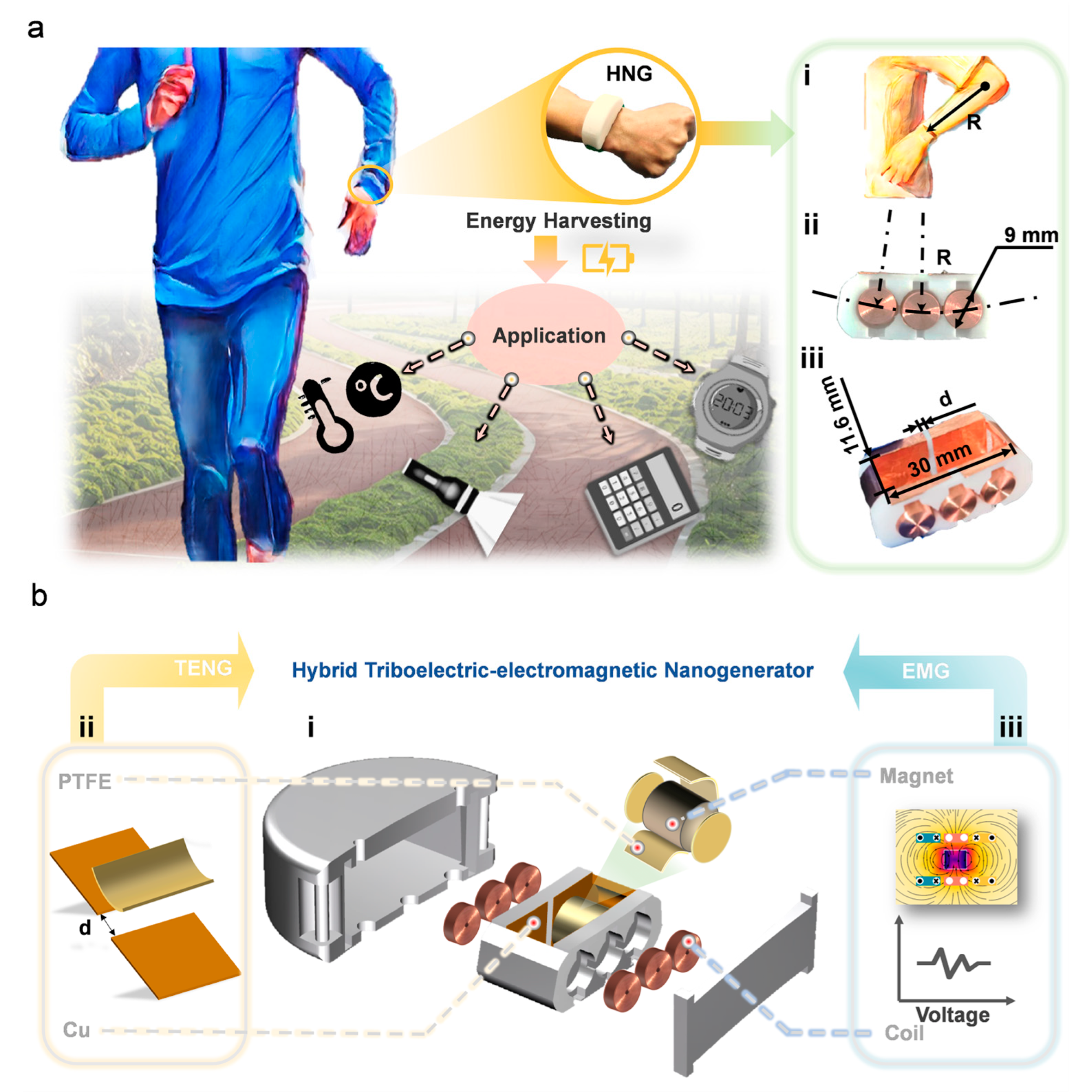
3.1. Devices Structure and Diagram of the HNG

Normally, people will unconsciously swing their arms when walking or running, and this arm swing is a kind of low-frequency biomechanical energy. To capture this low-frequency biomechanical energy into electrical energy, we developed an HNG to provide continuous energy to wearable devices such as thermometers, flashlights, or electronic meters. Figure 1a shows the structure and application scenario of the HNG. As shown in Figure 1a (i), the design of the coil layout arc is R = 185 mm based on the arm length of the experimenter. Figure 1a (ii) shows a coil with a diameter of 9 mm arranged in an arc of circumference R, and the selected coil parameters are shown in Table S1. Figure 1a (iii) shows the size of the container in which the magnet is placed. Figure 1b (i) shows an exploded view of the HNG, which allows a clearer view of the overall structural design of the temporal part of the HNG. The HNG consists of two parts, TENG and EMG. Figure 1b (ii) shows that when the magnet is rolling, the PTFE film on the magnetic surface and Cu on the inner wall rub to form TENG. The distance between the two Cu electrodes is d. According to Figure 1b (iii), the magnets reciprocate between the six coils to form the EMG. There are three sets of coils in total, where the two coils facing each other are connected in series as one set. The two parts are combined and encapsulated in a light-cured 3D-printed housing. Figure S1a,b show a physical view of the HNG and a physical view of a real person wearing it. The size of HNG can meet the requirements of carry-on and will not affect normal human activities’ mechanical movement.

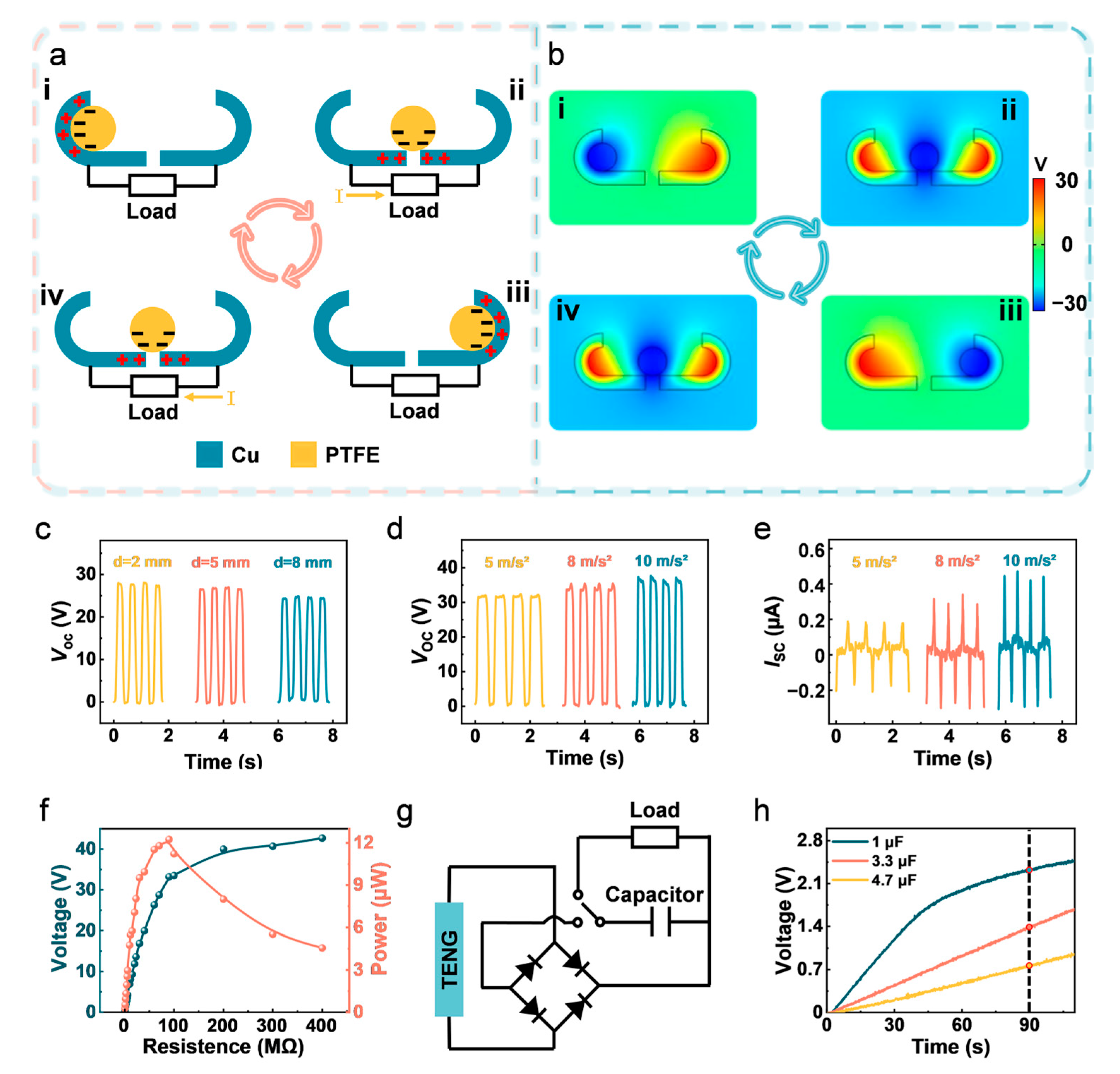
3.2. Working Principle and Performance of the TENG

Figure 2 illustrates the operating principle and performance of the TENG, which is based on the coupling of the triboelectric effect and electrostatic induction. A copper electrode contains side arcs, front, and back wall surfaces as well as a bottom surface. The two copper electrodes have a gap in the middle and are not connected to each other. For the sake of presentation, only the charge transfer on the front view is presented, and the charge transfer of the copper electrodes on the front and back walls is the same principle. The performance comparison of different friction layer materials in the TENG part can be found in Figure S1c, where the 250 um PTFE has the highest output.
Figure 2a shows the frictional motion of the magnets on the two copper electrodes under the excitation of the arm swing. PTFE is on the magnet surface as a separate layer and Cu as a conductive layer. The Cu films on both sides are used not only as friction materials for frictional charging but also as electrodes. The PTFE film on the surface of Cu and magnet forms a sliding independent mode TENG. The working principle of TENG can be elaborated by the four steps shown in Figure 2a. When the magnet is at the leftmost end, the contact between Cu and PTFE is a whole curved surface (state i), negative charges will accumulate on the PTFE surface and saturate the PTFE film by friction with Cu. During the right rolling (state ii), the PTFE membrane and the Cu electrode are in line contact friction. The friction electric effect will compensate for the negative charge on the PTFE surface, and the positive charge on the Cu electrode surface, and the positive charge in the circuit will flow into the right electrode. When the PTFE wrapped magnet hits the right wall, the surface is also touched, and all the positive charges are attracted to the surface of the right electrode (state iii). Subsequently, the PTFE rolls in the opposite direction from the right electrode to the left electrode, and then the movement direction is the same as the positive charge movement direction, forming a current in one direction of the load, which is the second half cycle of the power generation process (state iv). Finally, scroll to the far left to complete a generation cycle.
To further investigate the potential distribution of the TENG in the operational mode, the COMSOL Multiphysics software was used to simulate the potential distribution in different states of the TENG energy harvesting process, as shown in Figure 2b. We have used a two-dimensional electrostatic physics simulation to attach surface charge density to the surface of a copper electrode and a magnet. The total amount of charge on the magnet is equal to the sum of the total charge on the two copper electrodes. The detailed finite element model for COMSOL is described in Note S1 in the Supplementary Materials. Figure 2b shows the potential difference between the two copper electrodes that is utilized to generate the positive charge in the external circuit as the two electrodes’ VOC varies in response to the magnet’s rolling motion. The different colors indicate the different potential distributions on the contact surfaces: the blue area indicates a negative charge, and the red area indicates a positive charge. It is clear that when the PTFE independent layer is rolled from one electrode to the other, the maximum positive and negative potential differences between the two electrodes (states i and iii) are attained. According to Figure 2b, the simulated potential difference results can be directly up to 60 V. This means that the VOC of the two electrodes varies with the rolling of the magnet.
Noteworthy, the distance between the electrodes may have an effect on the output of TENG. A linear motor experimental platform that can simulate the biomechanical motion of the human body was chosen for the experimental settings in order to clarify the fundamental output performance of TENG. As shown in Figure 2c, the VOC was 27.981 V, 26.802 V and 24.368 V when the electrode distance was 2 mm, 5 mm and 8 mm, respectively. As the electrode distance increases, the VOC tends to decrease. This is due to the fact that when the distance decreases, electrons are exchanged more frequently between the two electrodes and the frictional contact area is larger. This is because as the distance increases, the contact area decreases, leading to a decrease in voltage. Through experiments comparing electrode distances, it was found that d = 2 mm was chosen as the most ideal electrode spacing.
The effect of acceleration on the TENG’s VOC was studied under the experimental conditions of a linear motor. Figure 2d,e show that the VOC of TENG at accelerations of 5 m/s2, 8 m/s2 and 10 m/s2 is 32.063 V, 35.378 V and 37.343 V, respectively, and the short-circuit current (ISC) is 0.388 μA, 0.589 μA and 0.752 μA. At an acceleration of 10 m/s2, both the VOC and the ISC reach their maximum, with an VOC of up to 37.199 V and a ISC of up to 0.763 μA. The acceleration is close to the acceleration of free fall motion and can be used as a more ideal acceleration parameter for the experiment. The acceleration is converted to frequency, as described in Note S2 in the Supplementary Materials. From Figure 2f, the load voltage decreases as the load resistance increases from zero to the maximum value and the load voltage reaches its maximum value. From the calculation, the maximum peak power of TENG reaches 12.25 μW at the optimum load resistance of 90 MΩ. Figure 2g shows the rectification circuit for the TENG. The current generated by the TENG passes through the rectifier bridge and charges the capacitor, which stores power to supply the load, which can operate normally. Then, we were able to obtain the charging curve in Figure 2h. Figure 2h shows that 1 μF, 3.3 μF and 4.7 μF capacitors can be charged to 2.325 V, 1.377 V and 0.761 V within 90 s, respectively. By verifying the charging performance of the TENG, it was shown that the TENG can capture the energy of the arm swing and reach a certain voltage.

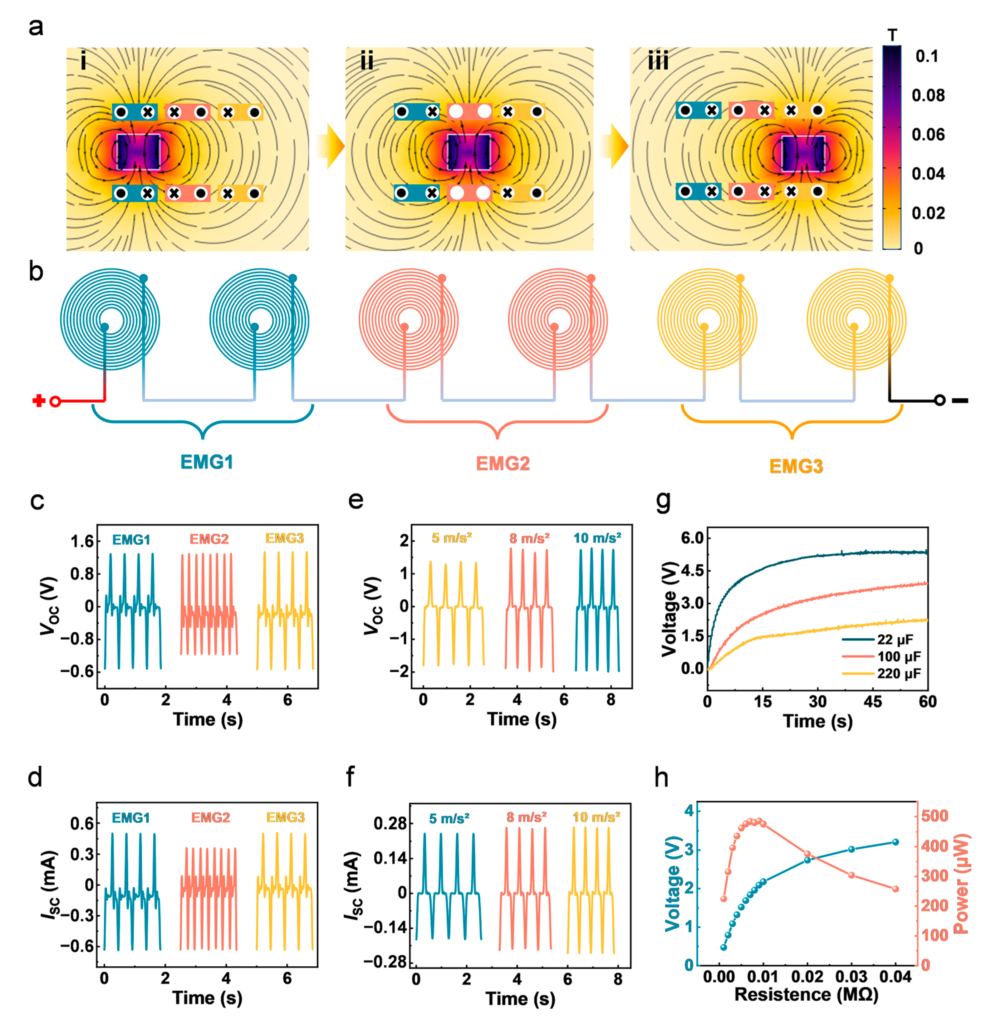
3.3. Working Principle and Performance of the EMG

The EMG is an important energy supply unit for the HNG. Figure 3 illustrates the working principle and corresponding output performance of the EMG. The working principle of EMG is based on the principle of electromagnetic induction, which converts mechanical energy into electrical energy. The two coils facing each other are connected in series to form one EMG1, naming the other two pairs of coils EMG2 and EMG3, respectively. The EMGs consist of EMG1, EMG2 and EMG3. As shown in Figure 3a, when the magnet cuts the coil along the transverse direction in the midst of the six coils, the magnetic field change and potential change are simulated using COMSOL Multiphysics software. The movement of the magnet with staggered polarities cuts the magnetic induction lines and thus creates an alternating magnetic field. According to Lenz’s law, when the magnet approaches the coil, the induced current is generated to resist the increase of the magnetic flux.
When the magnet leaves the coil, there will be an induced current in the opposite direction to resist the decrease in the magnetic flux. The current flow in the coil is deduced using the right-hand spiral rule, represented in Figure 3a. When the magnet rolls from the leftmost end to the right, the magnet wants to leave EMG1 and approach EMG2 and EMG3 (state i). The circuit direction of EMG1 is opposite to EMG2 and EMG3. When the magnet rolls from the middle, the magnet wants to leave EMG1 and EMG2 and approach EMG3 (state ii). The current flow in the EMG1 and EMG3 coils is in the opposite direction, when there is no current flow in the EMG2 coil. When the magnet rolls from to near the rightmost end, the magnet wants to leave EMG1 and approach EMG2 and EMG3 (state iii). EMG3 is in the opposite direction of EMG1 and EMG2. Figure 3a shows a schematic diagram of the direction of current flow in the EMG1, EMG2 and EMG3 coils.
Figure 3b shows the series connection between EMG1, EMG2 and EMG3 coils, and the parallel connection can be seen in Figure S2a. Figure 3c,d show the magnitude of the VOC and short circuit current of EMG1, EMG2 and EMG3, respectively. The open circuit voltages of EMG1, EMG2 and EMG3 are 2.8 V, 2.42 V and 2.866 V, and the short circuit currents of EMG1, EMG2 and EMG3 are 1.132 mA, 0.989 mA and 1.129 mA, respectively. It can be seen that in the same time period, the number of peaks of EMG2 located in the middle is twice the number of peaks of EMG1 and EMG3. This phenomenon is due to the magnets passing through the center coil more frequently.
More important than the output of an individual pair of coils is the output performance of the entire EMGs. In order to optimize the wiring method of EMGs, the voltage output performance was compared between three pairs of coils connected in series and in parallel. Figure S2b–d shows the VOCs and the ISC s of EMGs in parallel at accelerations of 5 m/s2, 8 m/s2 and 10 m/s2. Figure 3e shows the VOCs of EMGs in series at accelerations of 5 m/s2, 8 m/s2 and 10 m/s2: 3.168 V, 3.66 V and 3.677 V, respectively. Additionally, Figure 3f shows the ISC s are 0.425 mA, 0.492 mA and 0.506 mA, respectively. By comparing the output performance of series and parallel connection, the output voltage of the series connection method is higher than that of the parallel connection, so the series connection is chosen as the best wiring method. Figure 3g shows that EMGs can charge 22 μF, 100 μF and 220 μF to 5.33 V, 3.918 V and 2.2 V, respectively, in less than 60 s. By calculation, Figure 3h shows that the maximum instantaneous output power of the EMGs is 483.66 μW, which was attained with a matching resistor of 0.007 MΩ. Combined with the experimental results of TENG, it also fully demonstrates that TENG has the characteristics of high voltage with high matching resistance and EMG has the characteristics of high current and low internal resistance. Figure S2d shows the voltage output of TENG with EMG, and (e) shows the voltage output of TENG without EMG, demonstrating that EMG has almost no interference effect on the voltage output of TENG.

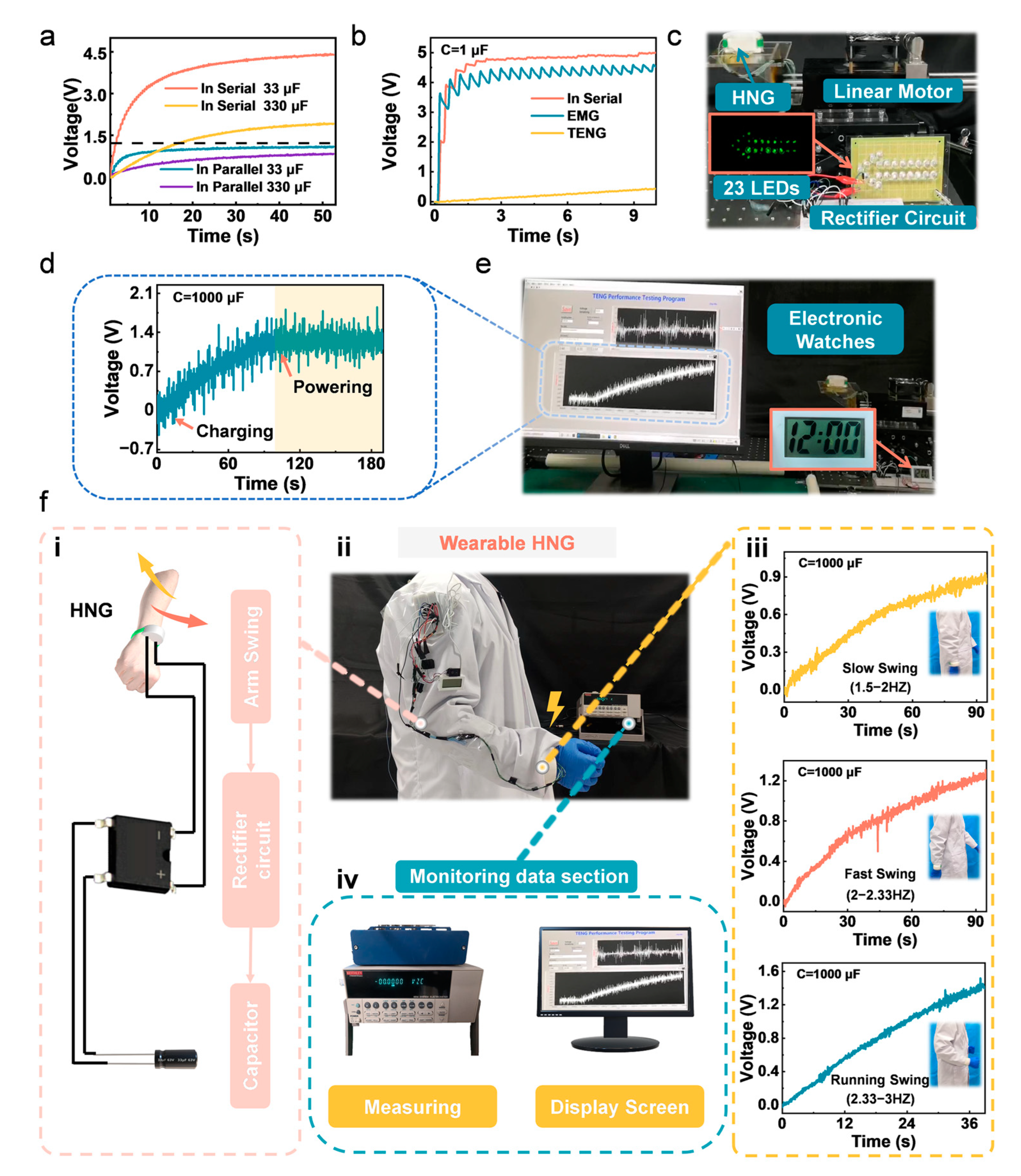
3.4. Hybrid Generator and Energy Storage

In order to achieve an overall better energy harvesting efficiency, the connection method between the EMGs and TENG was discussed. The two coils facing each other are connected in series to form one EMG1, naming the other two pairs of coils EMG2 and EMG3, respectively. The connection method between the TENG and the EMGs is discussed in order to obtain a better output performance. Figure 4a shows the charging capacitance curves of the TENG and EMGs in series and parallel connections. The boundary dashed line in Figure 4a indicates that the voltage achievable by series charging is greater than that of parallel charging. Based on the experimental results above, the series connection between the EMGs and TENG is preferred, and subsequent work was carried out using this connection method. In order to show that the hybrid and post-performance is better, Figure 4b shows the charging curves of the TENG alone with a 1 μF capacitor, the EMGs alone with a 1 μF capacitor and the TENG and the EMGs connected in series with a 1 μF capacitor, respectively. These three curves have a common feature. Charging is very fast in the first few seconds, mainly due to the low voltage and high current of the EMG. When the capacitor is charged to approximately the same voltage as the EMG, the EMG has almost no effect on the subsequent charging effect. At this point, benefiting from the high voltage characteristics of the TENG, the capacitor can continue charging to higher voltages to continuously collect vibration energy. Figure S3a includes a diagram of the rectifier circuit of the TENG and the EMGs in series connections.
In practice, Figure 4c shows that the HNG can also supply power to some electronic devices. It benefits from the high voltage of the TENG. The HNG can light up the 23 LEDs connected in the whole series, as shown in Movie S1. In order to be able to continuously supply power to an electronic device, it is necessary to add capacitors to the rectifier circuit. A 1000 μF capacitor was chosen. The full process can be seen in Movie S2. Figure 4d shows that for a 1000 μF, HNG takes 90 s to charge from 0 V to 1.2 V and continues to power the electronic device with the charging and discharging voltage d remaining approximately balanced. The power of the HNG is stored in the capacitor and can power the electronic watch (Figure 4e). Figure S3 shows (c) the stability and durability testing of EMG, and (d) the display of a temperature and humidity testing platform. The VOC of the TENG is influenced by (e) relative humidity and (f) temperature, while the VOC of the EMG is influenced by (g) relative humidity and (h) temperature. The results demonstrate that both TENG and EMG exhibit a certain stability and durability during operation. Due to the fact that the HNG is sealed, it is hardly significantly affected by environmental temperature and humidity.
In order to more clearly demonstrate the process of HNG power supply for wearable electrical devices, Figure 4f visualizes the flowchart of the HNG wearable power supply process. The experimenter wears a good device, and shakes their arm to generate electricity, which then passes through a rectifier bridge from AC to DC and charges capacitors (i). The voltage was measured using an electrometer and a data acquisition board during this process and the voltage changes were monitored with a computer display (iv). After the capacitor is charged, it can supply power to the electrical equipment on the arm and make it work normally (ii). The entire process can be seen in Movie S3; HNG lights up the thermometer in the video successfully.
The effect of an arm swinging fast or slow on charging was investigated, as in Figure 4f (iii). The difference between a fast and slow swing in Figure 4 relates to the frequency of arm swinging during different levels of physical activity. Generally speaking, the frequency of slow swinging is between 90–120 swings per minute, which translates to a frequency of 1.5–2 Hz. The frequency of fast swinging is between 120–140 swings per minute, which is 2–2.33 Hz. The frequency of the arm swinging while running is 2.33–3 Hz. The slow swing charges up to 0.847 V at 90 s, the fast swing charges up to 1.218 V at 90 s and the running swing charges up to 1.355 V at 36 s. It is concluded that the faster the amplitude and speed of the arm swing, the faster the charging rate. The above experiments show that the device can be applied in a real environment and performs well.

4. Conclusions

This paper presents the design of an HNG for harvesting biomechanical energy from an arm swinging motion. The performance testing and structural optimization of the TENG and EMG are conducted to maximize energy harvesting. Furthermore, finite element simulations are used to analyze and explain the mechanism of the TENG and EMGs for generating electricity. During arm swinging, a magnet covered with PTFE film moves relative to the curved cavity of HNG and acquires negative charges by friction with the Cu-coated inner wall of the cavity, resulting in a potential difference between two copper electrodes inside the curved cavity. The magnet’s movement changes the magnetic flux of the three pairs of coils on both sides of the arc trajectory, generating an induced electromotive force that converts the mechanical energy produced by arm swinging into electrical energy. The HNG was proven to have a constant energy output by lighting up 23 LEDs. The combination of two advantages, the high voltage of the TENG and the high current of the EMG, resulted in a faster and more stable charging of the capacitor. Experiments show that the HNG takes 90 s to charge from 0 V to 1.2 V for a 1000 μF. The application of the wearable HNG proved to be promising in the field of wearable devices as it was able to provide a constant power source for electronic watches and thermometers to power electronic devices for proper operation. This work demonstrates an effective biomechanical energy harvester, providing an innovative strategy for the energy supply of portable electronic devices and broadening future thinking on energy harvesting.

Supplementary Materials

The following supporting information can be downloaded at: https://www.mdpi.com/article/10.3390/nanoenergyadv3020007/s1, Figure S1: (a) Actual drawing of HNG. (b) The physical picture of HNG worn on the hand; Figure S2: (a) Connection in parallel of EMGs. (b) The VOC of EMGs in parallel at accelerations of 5 m/s2, 8 m/s2, 10 m/s2. (c) The ISC of EMGs in parallel at accelerations of 5 m/s2, 8 m/s2, 10 m/s2; Figure S3. (a) Schematic diagram of the rectifier circuit of TENG and EMGs in series connection; Table S1: Coil parameters; Video S1: 23 LEDs lighting up by the HNG; Video S2: Driving an electronic watch by the HNG on the linear motor experimental platform; Video S3: Powering a temperature sensor by the wearable HNG.

Author Contributions

Conceptualization, Z.W. and L.W.; methodology, J.Z.; software, J.Z.; validation, J.Z., Z.C. and C.H.; formal analysis, J.Z.; investigation, J.Z.; data curation, J.Z.; writing—original draft preparation, J.Z.; writing—review and editing, J.Z. and X.W.; visualization, J.Z.; supervision, Z.W. and L.W.; project administration, Z.W.; funding acquisition, Z.W. All authors have read and agreed to the published version of the manuscript.

Funding

The research was supported by the National Natural Science Foundation of China (61503051).

Data Availability Statement

Data is contained within the article or Supplementary Materials.

Conflicts of Interest

The authors declare no competing financial interest.

References

  1. Reeder, B.; Chung, J.; Lyden, K.; Winters, J.; Jankowski, C.M. Older women’s perceptions of wearable and smart home activity sensors. Inform. Health Soc. Care 2020, 45, 96–109. [Google Scholar] [CrossRef] [PubMed]
  2. Tang, Y.; Zhou, H.; Sun, X.; Feng, T.; Zhao, X.; Wang, Z.; Liang, E.; Mao, Y. Cotton-based naturally wearable power source for self-powered personal electronics. J. Mater. Sci. 2020, 55, 2462–2470. [Google Scholar] [CrossRef]
  3. Kim, Y.; Lee, D.; Seong, J.; Bak, B.; Choi, U.H.; Kim, J. Ionic liquid-based molecular design for transparent, flexible, and fire-retardant triboelectric nanogenerator (TENG) for wearable energy solutions. Nano Energy 2021, 84, 105925. [Google Scholar] [CrossRef]
  4. Walden, R.; Aazem, I.; Babu, A.; Pillai, S.C. Textile-Triboelectric nanogenerators (T-TENGs) for wearable energy harvesting devices. Chem. Eng. J. 2023, 451, 138741. [Google Scholar] [CrossRef]
  5. Wang, Z.L. Entropy theory of distributed energy for internet of things. Nano Energy 2019, 58, 669–672. [Google Scholar] [CrossRef]
  6. Zou, Y.; Raveendran, V.; Chen, J. Wearable triboelectric nanogenerators for biomechanical energy harvesting. Nano Energy 2020, 77, 105303. [Google Scholar] [CrossRef]
  7. Song, C.; Xia, K.; Xu, Z. A self-supported structure hybrid triboelectric/piezoelectric nanogenerator for bio-mechanical energy harvesting and pressure sensing. Microelectron. Eng. 2022, 256, 111723. [Google Scholar] [CrossRef]
  8. Vivekananthan, V.; Kim, W.J.; Alluri, N.R.; Purusothaman, Y.; Khandelwal, G.; Kim, S.-J. A highly reliable contact-separation based triboelectric nanogenerator for scavenging bio-mechanical energy and self-powered electronics. J. Mech. Sci. Technol. 2021, 35, 2131–2139. [Google Scholar] [CrossRef]
  9. Xia, K.; Xu, Z. Double-piezoelectric-layer-enhanced triboelectric nanogenerator for bio-mechanical energy harvesting and hot airflow monitoring. Smart Mater. Struct. 2020, 29, 095016. [Google Scholar] [CrossRef]
  10. Wang, X.; Wang, Z.L.; Yang, Y. Hybridized nanogenerator for simultaneously scavenging mechanical and thermal energies by electromagnetic-triboelectric-thermoelectric effects. Nano Energy 2016, 26, 164–171. [Google Scholar] [CrossRef]
  11. Tang, X.; Lin, T.; Zuo, L. Design and Optimization of a Tubular Linear Electromagnetic Vibration Energy Harvester. IEEE/ASME Trans. Mechatron. 2014, 19, 615–622. [Google Scholar] [CrossRef]
  12. Wang, H.; Xu, C.; Pan, X.; Cheng, T. A triboelectric–electromagnetic hybrid generator for scavenging low-frequency oscillation energy from the environment and human body. J. Mater. Sci. 2022, 57, 21143–21155. [Google Scholar] [CrossRef]
  13. Qi, Y.; Liu, G.; Bu, T.; Zeng, J.; Zhang, Z.; Zhang, C. Ferromagnetic-Based Charge-Accumulation Triboelectric Nanogenerator With Ultrahigh Surface Charge Density. Small 2022, 18, 2201754. [Google Scholar] [CrossRef]
  14. Qi, Y.; Liu, G.; Gao, Y.; Bu, T.; Zhang, X.; Xu, C.; Lin, Y.; Zhang, C. Frequency Band Characteristics of a Triboelectric Nanogenerator and Ultra-Wide-Band Vibrational Energy Harvesting. ACS Appl. Mater. Interfaces 2021, 13, 26084–26092. [Google Scholar] [CrossRef] [PubMed]
  15. Qi, Y.; Liu, G.; Kuang, Y.; Wang, L.; Zeng, J.; Lin, Y.; Zhou, H.; Zhu, M.; Zhang, C. Frequency band broadening and charge density enhancement of a vibrational triboelectric nanogenerator with two stoppers. Nano Energy 2022, 99, 107427. [Google Scholar] [CrossRef]
  16. Zhao, J.; Zhen, G.; Liu, G.; Bu, T.; Liu, W.; Fu, X.; Zhang, P.; Zhang, C.; Wang, Z.L. Remarkable merits of triboelectric nanogenerator than electromagnetic generator for harvesting small-amplitude mechanical energy. Nano Energy 2019, 61, 111–118. [Google Scholar] [CrossRef]
  17. Ding, S.; Zhai, H.; Shao, Y.; Lei, R. Isometric Double-Layer Staggered Chain Teeth Triboelectric Nanogenerator. Micromachines 2022, 13, 421. [Google Scholar] [CrossRef]
  18. Mehamud, I.; Marklund, P.; Björling, M.; Shi, Y. Machine condition monitoring enabled by broad range vibration frequency detecting triboelectric nano-generator (TENG)-based vibration sensors. Nano Energy 2022, 98, 107292. [Google Scholar] [CrossRef]
  19. Hou, C.; Chen, T.; Li, Y.; Huang, M.; Shi, Q.; Liu, H.; Sun, L.; Lee, C. A rotational pendulum based electromagnetic/triboelectric hybrid-generator for ultra-low-frequency vibrations aiming at human motion and blue energy applications. Nano Energy 2019, 63, 103871. [Google Scholar] [CrossRef]
  20. Salauddin, M.; Toyabur, R.M.; Maharjan, P.; Rasel, M.S.; Kim, J.W.; Cho, H.; Park, J.Y. Miniaturized springless hybrid nanogenerator for powering portable and wearable electronic devices from human-body-induced vibration. Nano Energy 2018, 51, 61–72. [Google Scholar] [CrossRef]
  21. Li, T.; Pan, P.; Yang, Z.; Yang, X. Research on PDMS TENG of laser etch 3D structure. J. Mater. Sci. 2022, 57, 6723–6733. [Google Scholar] [CrossRef]
  22. Zhang, S.L.; Jiang, Q.; Wu, Z.; Ding, W.; Zhang, L.; Alshareef, H.N.; Wang, Z.L. Energy Harvesting-Storage Bracelet Incorporating Electrochemical Microsupercapacitors Self-Charged from a Single Hand Gesture. Adv. Energy Mater. 2019, 9, 1900152. [Google Scholar] [CrossRef]
  23. Bai, S.; Cui, J.; Zheng, Y.; Li, G.; Liu, T.; Liu, Y.; Hao, C.; Xue, C. Electromagnetic-triboelectric energy harvester based on vibration-to-rotation conversion for human motion energy exploitation. Appl. Energy 2023, 329, 120292. [Google Scholar] [CrossRef]
  24. Deng, Z.; Xu, L.; Qin, H.; Li, X.; Duan, J.; Hou, B.; Wang, Z.L. Rationally Structured Triboelectric Nanogenerator Arrays for Harvesting Water-Current Energy and Self-Powered Sensing. Adv. Mater. 2022, 34, 2205064. [Google Scholar] [CrossRef]
  25. Shi, Q.; Wang, H.; Wu, H.; Lee, C. Self-powered triboelectric nanogenerator buoy ball for applications ranging from environment monitoring to water wave energy farm. Nano Energy 2017, 40, 203–213. [Google Scholar] [CrossRef]
  26. Han, C.; Cao, Z.; Yuan, Z.; Zhang, Z.; Huo, X.; Zhang, L.; Wu, Z.; Wang, Z.L. Hybrid Triboelectric-Electromagnetic Nanogenerator with a Double-Sided Fluff and Double Halbach Array for Wave Energy Harvesting. Adv. Funct. Mater. 2022, 32, 2205011. [Google Scholar] [CrossRef]
  27. Zhao, J.; Mu, J.; Cui, H.; He, W.; Zhang, L.; He, J.; Gao, X.; Li, Z.; Hou, X.; Chou, X. Hybridized Triboelectric-Electromagnetic Nanogenerator for Wind Energy Harvesting to Realize Real-Time Power Supply of Sensor Nodes. Adv. Mater. Technol. 2021, 6, 2001022. [Google Scholar] [CrossRef]
  28. Guo, H.; Leng, Q.; He, X.; Wang, M.; Chen, J.; Hu, C.; Xi, Y. A Triboelectric Generator Based on Checker-Like Interdigital Electrodes with a Sandwiched PET Thin Film for Harvesting Sliding Energy in All Directions. Adv. Energy Mater. 2015, 5, 1400790. [Google Scholar] [CrossRef]
  29. He, X.; Wen, Q.; Sun, Y.; Wen, Z. A low-frequency piezoelectric-electromagnetic-triboelectric hybrid broadband vibration energy harvester. Nano Energy 2017, 40, 300–307. [Google Scholar] [CrossRef]
  30. Wang, S.; Liao, W.; Zhang, Z.; Liao, Y.; Yan, M.; Kan, J. Development of a novel non-contact piezoelectric wind energy harvester excited by vortex-induced vibration. Energy Convers. Manag. 2021, 235, 113980. [Google Scholar] [CrossRef]
  31. Wu, Z.; Tang, J.; Zhang, X.; Yu, Z. An energy harvesting bracelet. Appl. Phys. Lett. 2017, 111, 013903. [Google Scholar] [CrossRef]
  32. Guo, Y.; Chen, Y.; Ma, J.; Zhu, H.; Cao, X.; Wang, N.; Wang, Z.L. Harvesting wind energy: A hybridized design of pinwheel by coupling triboelectrification and electromagnetic induction effects. Nano Energy 2019, 60, 641–648. [Google Scholar] [CrossRef]
  33. Rana, S.M.S.; Rahman, M.T.; Salauddin, M.; Maharjan, P.; Bhatta, T.; Cho, H.; Park, J.Y. A human-machine interactive hybridized biomechanical nanogenerator as a self-sustainable power source for multifunctional smart electronics applications. Nano Energy 2020, 76, 105025. [Google Scholar] [CrossRef]
  34. Salauddin, M.; Toyabur, R.M.; Maharjan, P.; Rasel, M.S.; Cho, H.; Park, J.Y. Design and experimental analysis of a low-frequency resonant hybridized nanogenerator with a wide bandwidth and high output power density. Nano Energy 2019, 66, 104122. [Google Scholar] [CrossRef]
  35. Zhang, B.; Zhang, S.; Li, W.; Gao, Q.; Zhao, D.; Wang, Z.L.; Cheng, T. Self-Powered Sensing for Smart Agriculture by Electromagnetic-Triboelectric Hybrid Generator. ACS Nano 2021, 15, 20278–20286. [Google Scholar] [CrossRef]
  36. Zhong, X.; Yang, Y.; Wang, X.; Wang, Z.L. Rotating-disk-based hybridized electromagnetic-triboelectric nanogenerator for scavenging biomechanical energy as a mobile power source. Nano Energy 2015, 13, 771–780. [Google Scholar] [CrossRef]
  37. Wu, Y.; Wang, X.; Yang, Y.; Wang, Z.L. Hybrid energy cell for harvesting mechanical energy from one motion using two approaches. Nano Energy 2015, 11, 162–170. [Google Scholar] [CrossRef]
Figure 1. The structure and application scenarios of the HNG. (a) Structural design and application of the HNG. (i) Arm swing diagram. (ii) Schematic diagram of arc cavity structure. (iii) Schematic diagram of the cavity. (b) Schematic diagram of the HNG. (i) Exploded diagram of the HNG. (ii) Schematics of the EMG. (iii) Schematics of the TENG.
Nanoenergyadv 03 00007 g001
Figure 2. Working mechanism and output performance of the TENG. (a) (i−iv)The working mechanism of the TENG. (b) (i−iv) Corresponding electric potential distributions for the TENG at different positions calculated by COMSOL simulations. (c) Comparison of different VOC of the TENG for different distances between electrodes. (d) Comparison of VOC for different accelerations of TENG. (e) Comparison of ISC for different accelerations of TENG. (f) Output voltage and power of the TENG under variable load resistance. (g) The rectification circuit for the TENG. (h) Charging voltage curves for different capacitors at 10 m/s2.
Nanoenergyadv 03 00007 g002
Figure 3. Working mechanism and output performance of the EMGs. (a) Finite element simulation results of the working principle of the EMGs and magnetic field distribution in different states. (i) The state of the magnet on the far left. (ii) The state of the magnet in the middle. (iii) The state of the magnet on the far right. (b) Series representation of the EMGs. (c) The VOC of the EMGs at 10 m/s2. (d) The ISC of the EMGs at 10 m/s2. (e) Comparison of VOC for different accelerations of the EMGs. (f) Comparison of ISC for different accelerations of the EMGs. (g) Charging voltage curves for different capacitors at 10 m/s2. (h) Output voltage and power of the TENG units connected in series under variable load resistance.
Nanoenergyadv 03 00007 g003
Figure 4. The applications of the HNG. (a) Charging voltage curves for different capacitors connected in series and in parallel. (b) Charging voltage curves for 1 μF capacitors in the TENG, the EMGs and in series. (c) Photograph of the HNG lighting up 23 LEDs on a linear motor. (d) Charging curve of the electronic watch. (e) Photograph of the HNG powering an electronic watch on a linear motor. (f) Process diagram of the wearable HNG. (i) Electric energy storage process. (ii) Energy harvesting application diagram for collecting arm energy. (iii) Charging curves at different swing arm speeds. (iv) Schematic diagram of the instruments used for data acquisition.
Nanoenergyadv 03 00007 g004
Disclaimer/Publisher’s Note: The statements, opinions and data contained in all publications are solely those of the individual author(s) and contributor(s) and not of MDPI and/or the editor(s). MDPI and/or the editor(s) disclaim responsibility for any injury to people or property resulting from any ideas, methods, instructions or products referred to in the content.

