Review

Perspective on Development of Piezoelectric Micro-Power Generators

1
Institute of Advanced Materials, Hubei Normal University, Huangshi 435002, China
2
Department of Mechanical and Aerospace Engineering, Hong Kong University of Science and Technology, Clear Water Bay, Hong Kong, China
3
Department of Mechanical Engineering, City University of Hong Kong, Hong Kong, China
4
Institute for Advanced Study, Shenzhen University, Shenzhen 518051, China
*
Authors to whom correspondence should be addressed.
Nanoenergy Adv. 2023, 3(2), 73-100; https://doi.org/10.3390/nanoenergyadv3020005
Submission received: 31 December 2022 / Revised: 27 March 2023 / Accepted: 28 March 2023 / Published: 4 April 2023

Abstract

:
Anthropogenetic environmental deterioration and climate change caused by energy production and consumption pose a significant threat to the future of humanity. Renewable, environmentally friendly, and cost-effective energy sources are becoming increasingly important for addressing future energy demands. Mechanical power is the most common type of external energy that can be converted into useful electric power. Because of its strong electromechanical coupling ability, the piezoelectric mechanism is a far more successful technique for converting mechanics energy to electrical energy when compared to electrostatic, electromagnetic, and triboelectric transduction systems. Currently, the scientific community has maintained a strong interest in piezoelectric micro-power generators because of their great potential for powering a sensor unit in the distributed network nodes. A national network usually has a large mass of sensor units distributed in each city, and a self-powered sensor network is eagerly required. This paper presents a comprehensive review of the development of piezoelectric micro-power generators. The fundamentals of piezoelectric energy conversion, including operational modes and working mechanisms, are introduced. Current research progress in piezoelectric materials including zinc oxide, ceramics, single crystals, organics, composite, bio-inspired and foam materials are reviewed. Piezoelectric energy harvesting at the nano- and microscales, and its applications in a variety of fields such as wind, liquid flow, body movement, implantable and sensing devices are discussed. Finally, the future development of multi-field coupled, hybrid piezoelectric micropower generators and their potential applications are discussed.

Graphical Abstract

1. Introduction

For over a century, fossil fuels have been widely regarded as the primary source of energy, without adequate consideration of their environmental impact; however, the world’s expanding population is pushing the planet to the breaking point regarding climate change. Additionally, the overgrowth of the current population makes it hard to provide enough power for future generations because we use too much fossil fuel. However, renewable sources of energy could be a solution to these problems, even though they will not be able to solve the energy crisis on their own in the next few decades [1,2].
Since the beginning of the twenty-first century, research and development regarding tiny, portable, and long-distance, low-power technologies has resulted in the creation of unconventional power supplies [3,4]. Batteries, the conventional chemical energy source, have some serious problems, such as their leading to environmental pollution after being discarded, and also their limited lifetime, while rechargeable batteries need to frequently recharge, which will be a large problem when they are used in great numbers in the distributed website nodes in the Internet of Things. Micro-power harvesting is an effective method of producing small amounts of electric energy from external environmental energy sources, such as solar [5], thermal [6], wind [7], vibration [8], and human motion [9]. The primary purpose of small- or micro-energy-collecting is to replace conventional chemical batteries and/or self-power rechargeable batteries to increase the lifetime of remotely distributed sensor units or portable devices. Undoubtedly, micro-energy collection from ambient energy and radiation in the environment also help to protect the ecosystem against further damage because they are renewable and environmentally beneficial [10]. Recent research on energy harvesting has focused on several transduction mechanisms: (i) electromagnetic, (ii) piezoelectric, (iii) photovoltaic, (iv) thermoelectric, and (v) tri-boelectric mechanisms. The benefits and drawbacks of various energy harvesting technologies have been thoroughly examined [11,12]. The bulk of the research focused on piezoelectric transduction because of its relatively high power density, efficient energy conversion, simpler topology, and high scalability, which make it a viable alternative [13,14,15]. Compared with electromagnetic micro-power generators, the disadvantages of the piezoelectric micro-power generators include their low output current and high output impedance, but piezoelectric generators are more efficient than electromagnetic generators when working in a low-frequency range, and they also have more advantages than triboelectric generators. Consequently, piezoelectric materials have found numerous applications in various fields, such as sensor technology [16,17,18], actuators [19,20], nanogenerators [21,22,23,24], MEMS devices [25,26], portable electronics [27,28], and biomedicine [29,30].
Most piezoelectric harvesting systems produce a power output within a range from 1 μw to 1 mw, and the primary use of piezoelectric energy capture is to supply small or micro-energy for microscale electronics such as implantable biomedical devices, wireless sensor nodes, and portable electronics. By utilizing piezoelectric energy capture, these devices can operate on a permanent, self-sufficient power supply without the need for maintenance or replacement. Furthermore, this independent power supply enables electronic equipment to be incorporated in structures or deployed in far-off places. With the recent increase in low-power electronics, piezoelectric energy harvesting has received substantial interest from the worldwide research community in the last 20 years. This article provides a comprehensive review of recent advances in piezoelectric micro-power sources. It specifically compiles, discusses, and summarizes the latest literature on piezoelectric materials and device applications.

2. Piezoelectric Mechanism and Theory Analysis

2.1. Piezoelectric Effect

Piezoelectricity is a phenomenon exhibited by certain materials that enables them to convert mechanical energy into electrical energy, as well as generate mechanical energy from an applied AC electric field, through the use of external input vibrations or waves; this unique feature distinguishes them from other types of materials. In 1880, Pierre and Jacques Curie discovered the phenomena of piezoelectricity when they performed research on crystals of quartz, tourmaline, and Rochelle salt. This great finding made them pioneers in the piezoelectric field [31].
It is known that there are two separate piezoelectric effects: (i) the direct effect and (ii) the inverse effect [32]. Under a tensile or compressive stress, an electric polarization change in the material induces charge or voltage via direct piezoelectric action. In the inverse effect, the present of electric potential causes a strain or deformation in the material. This behavior can be observed in numerous naturally occurring crystalline substances, including quartz, Rochelle salt, and even biological bones. The piezoelectric properties of artificially engineered materials, such as lithium niobate and lead zirconate titanate (PZT), exhibit a greater degree of effectiveness.
In electromechanical coupling devices, researchers normally use the term of “direct piezoelectric effect” to describe the transduction of mechanical energy into electrical energy, and the term of “converse piezoelectric effect” to describe the opposite energy transduction process. Apparently, piezoelectric-based energy transduction relies on the direct piezoelectric effect. The constitutive Equations (1) and (2) for both effects are provided in the next section [33].
S i = s i j E T j + d m i E m ( i ,   j   =   1 ,   2 , , 6 ;   m ,   k   =   1 ,   2 ,   3 )
D k = d k j T j + ε k m T E m
where Tj is stress, dmi is the piezoelectric constant, Si is strain, Dk is electric displacement, and Em is the electric field. s i j E is the mechanical compliance at constant electric field E; ε k m T is the permittivity of the material at constant stress T. The subscripts i, j, and m, k refer to the different directions in the material coordinate system.
The three principal axes of a piezoelectric element are designated 1, 2, and 3 (Figure 1), which correspond to the Cartesian coordinate axes x, y, and z. The direction along the z-axis, or direction “3”, reveals the polarization orientation (the effect of poling). In the piezoelectric equation, the strains S1, S2, and S3 (Si for i = 1, 2, 3) correspond to three principal strains, respectively, in an element; while strains S4, S5, and S6 (Si for i = 4, 5, 6) correspond to shear/rotation strains around three axes (1, 2, and 3), respectively. The stress Ti has a similar definition to Si.
Piezoelectric constants dmi indicate the operation mode of one piezoelectric element or device under the applied electric field Em (converse piezoelectric effect, see Equation (1)) or under the applied stress Tj (direct piezoelectric effect, see Equations (1) and (2)). For example, if the piezoelectric element is operating in a converse piezoelectric effect, three frequently used piezoelectric constants, d31, d33, d15, correspond to three basic strain or deformation modes: (i) the principal strain S1 (along 1-axis) under E3, (ii) the principal strain S3 (along 3-axis) under E3, and (iii) the shear strain S5 (around 2-axis) under E1, respectively. For simplification, they are also called 31-mode, 33-mode, and 15-mode, respectively.
When operating under a direct piezoelectric effect (see Equations (1) and (2)), piezoelectric constants d31, d33, d15 correspond to three basic electric displacement modes (equivalent to charge density, C/m2): (i) the electric displacement D1 along 1-axis under T3 (applied in the direction of polarization), (ii) the electric displacement D3 along 3-axis under T3, and (iii) the electric displacement D1 along 1-axis under T5, respectively. Similarly, they are also often called 31-mode, 33-mode, and 15-mode, respectively. Piezoelectric energy harvesting devices normally work in one of three basic modes.

2.2. Theoretical Analysis on Piezoelectric Energy Harvester

A piezoelectric energy harvesting device, as stated above, normally works in one of three basic electric displacement modes or a combination of these modes based on the direct piezoelectric effect. For example, an applied dynamic mechanical stress T3 (or Δσ3) induces the generation of electrical charges via electric displacement D3 (or d33) mode when Δσ3 is applied in the polarization direction of the piezoelectric element. In this case, the induced charge (Q3 = D3A) across two opposite electrode faces of a tested sample with an area (A) is given by
Q 3 = d 33 · A · Δ σ 3
When the piezoelectric harvester is under open-circuit conditions, the load impedance is infinite; hence, its output voltage under Δσ3 is determined by
V = Q3/C
where C = A ε 33 T h is the capacitance of the device. After substituting Equation (3) into Equation (4), output voltage V can be obtained as
V = g 33 · h · Δ σ 3
where g 33 = d 33 / ε 33 T is the piezoelectric voltage constant, h is material thickness, and ε 33 T is the permittivity at a constant stress T in 33-mode. Furthermore, the generated energy E by the piezoelectric harvester under Δσ3 is given by
E = 1 2 C V 2
By substituting Equation (5) into Equation (6), finally, we can obtain
E = 1 2 V v o l u m e · ( d 33 g 33 ) · Δ σ 3 2
where Vvolume is the volume of the piezoelectric material, and d 33 g 33 is a feature of merit of piezoelectric energy materials, indicating the electromechanical coupling ability. To maximize the energy generated by a piezoelectric device for a given volume and Δσ3, it is advantageous to select piezoelectric materials that exhibit high values of both the piezoelectric charge constant d33 and the piezoelectric voltage constant g33.

3. Piezoelectric Materials

When certain materials, such ase ferroelectrics, do not possess a center of symmetry in their crystal structures, they exhibit a change in polarization under mechanical deformation or strain. Piezoelectric materials are capable of producing electrical energy through the application of minimal mechanical forces.
Since the discovery of barium titanate (BaTiO3) and lead zirconate titanate (PZT) ferroelectric ceramics in the 1940s and 1950s, respectively, researchers have noticed piezoelectricity phenomena in a vast array of synthetic materials. Piezoelectric materials exhibit diverse electromechanical, ferroelastic, dielectric, and thermal characteristics. However, to induce piezoelectric behavior, a critical step of electric poling must be carried out to align the random domains in piezoelectric materials. Perovskite-structured inorganic ceramic and crystal materials often demonstrate superior piezoelectric performances compared to organic polymer materials such as piezoelectric Polyvinylidene Fluoride (PVDF). However, the soft and flexible behaviors of the piezoelectric PVDF polymer make it more suitable for energy harvesting when embedded in flexible, wearable electronic devices. The following sections introduce several typical piezoelectric materials that have potential for piezoelectric energy harvester applications.

3.1. Zinc Oxide (ZnO)

Wurtzite zinc oxide (ZnO) crystal is a wide-bandgap oxide semiconductor material that exhibits piezoelectric properties owing to its non-centrosymmetric crystal structure. The crystal structure consists of alternately stacked planes of the O2– ions plane and Zn2+ ions plane in tetrahedral coordination along the c-axis [34,35,36]. The piezoelectric constant d33 of ZnO has been observed to be between 10 and 12 pC N–1. Z.L. Wang et al. published the first piezoelectric nanogenerator based on ZnO nanowires in 2006. Over the years, there has been significant interest in piezoelectric energy-harvesting technologies, which are capable of directly converting small-scale mechanical vibration energy into electrical energy [37].
In Figure 2a, a dielectric layer and ZnO nanowires were positioned between textile substrates to create a hybrid nanogenerator on a woven textile substrate [38]. As demonstrated by the SEM images in Figure 2b,c, the ZnO nanowires grew uniformly on the textile substrate. Figure 2d displays the rolled textile substrate, indicating its exceptional flexibility. When a 100 Hz sound wave with a 100 dB intensity was applied, the textile-based nanogenerators produced an output voltage of 8 V and a current of 2.5 μA. This increase in voltage can be attributed to the combined effects of the piezoelectric properties of ZnO nanowires and the electrostatic properties of the dielectric film.
Kim et al. [39] reported the successful generation of piezoelectric power on ZnO nanosheets and an anionic nanoclay layer with aluminum electrodes. The ZnO nanosheet/anionic layer was synthesized at 95 °C using an aqueous solution of zinc nitrate. When a compressive force of 4 kgf was applied, the output voltage and power density of the ZnO nanosheets were 0.7 V and 11.8 W cm−2, respectively. The researchers postulated that the power generation was the result of a combination of the semiconducting and piezoelectric effects in ZnO nanosheets, as well as the self-formation of the anionic nanoclay layer.

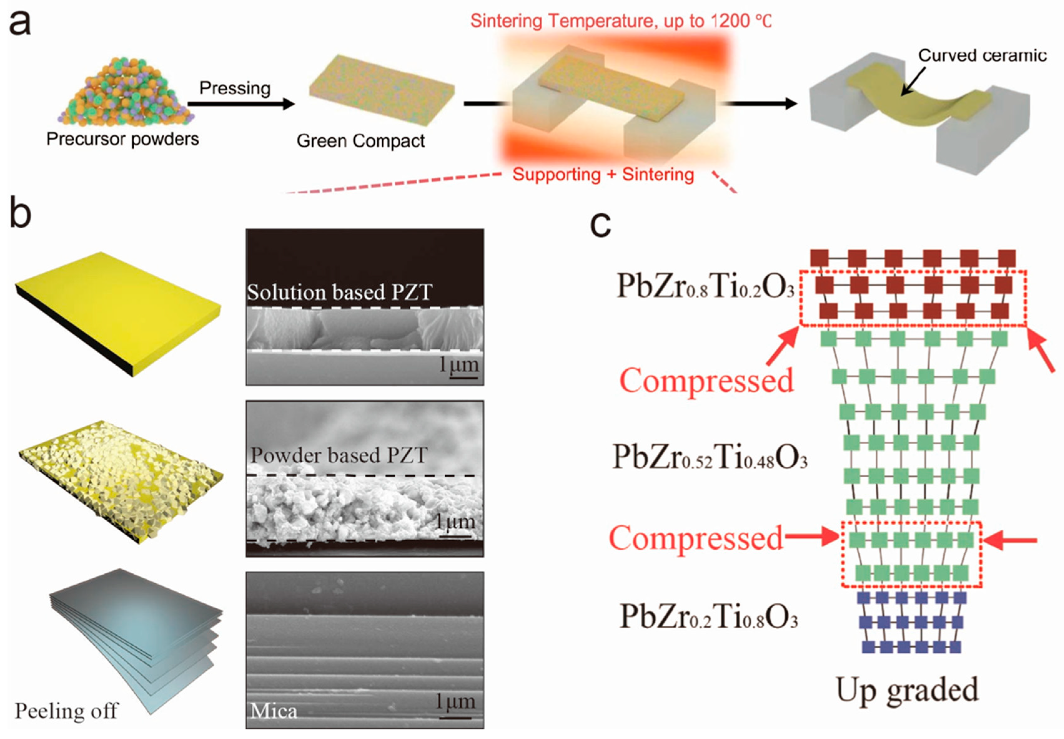
3.2. Piezoelectric Ceramics

Piezoelectric materials have been extensively studied over the past century, with the perovskite lead zirconate titanate (PZT) ceramic being the most widely used. PZT ceramics are polycrystalline materials that can be doped with niobium or manganese to form soft or hard types of ceramic, respectively. These materials have direct coupling, which allows for operation without bias voltages, and they are capable of generating high voltages on the order from tens to hundreds of volts. Due to these properties, piezoelectric ceramics have found significant applications in sensors, actuators, and transducers [40].
Gao et al. developed a high-performance PNN-PZT (0.55Pb(Ni1/3Nb2/3)O3–0.135PbZrO3–0.315PbTiO3) ceramic, which has an effective piezoelectric coefficient of 1753 pC/N [41]. The PNN-PZT ceramic-based harvester has a output power of 14.0 mW, which is nearly equal to PMN-PT single-crystal harvester. Liu et al. constructed a gradient PZT structure for energy harvesting; the instantaneous power output reached 1.1 mW, which was sufficient to illuminate 96 LEDs [42]. Shan et al. developed curved PZT ceramics, assisted by the function of gravity during the sintering process, which allowed for broader, more complex application scenarios for energy harvesters, as illustrated in Figure 3a [43]. To deal with the fact that bulk PZT cannot be used for flexible devices, in Figure 3b,c, Liu et al. developed a simple and fast technology for flexible energy harvesters on mica and discovered the optimization routes for the piezoelectric performances [44,45]. This technology inspired the application of piezoelectric materials in the field of flexible electronics.
Although PZT-based ceramics have been widely used, their lead content raises environmental concerns. As a result, the search for alternative compositions has become a major research focus, with ongoing efforts to develop new materials. The most prevalent of these are potassium sodium niobate (K0.5Na0.5)NbO3 and sodium bismuth titanate (Bi0.5Na0.5)TiO3 [46,47]. Shin et al. investigated the feasibility of employing lead-free (1 − x)Ba(Zr0.2Ti0.8)O3–x(Ba0.7Ca0.3)TiO3 in piezoelectric energy harvesting. A record-breaking output energy density of 158 J/cm3 for lead-free ceramics was attained [48]. The output performances of piezoelectric nanogenerators fabricated using lead-free piezoelectric materials are presented in Table 1.

3.3. Piezoelectric Single Crystals

Perovskite ferroelectric single crystals have attracted tremendous interest from both theoretical and practical point of views because of their extensive uses in various sectors, including medical ultrasound, sensors and actuators, and microelectronic devices. Crystals, for instance, enable the complete utilization of piezoelectric anisotropy to improve their properties via domain engineering. This results in the highest piezoelectric coefficients of up to one order of magnitude greater than their polycrystalline counterparts. On the other hand, theoretical studies of single-crystal materials are essential for enhancing fundamental physical understanding and promoting the intrinsic dielectric, elastic, and piezoelectric properties of perovskite ferroelectric single crystals.
The most commonly used perovskite ferroelectric piezoelectric single crystals include the lead magnesium niobate–lead titanate solid solution (PMN-PT) and lead zinc niobate–lead titanate (PZN-PT), etc. [64]. Their electromechanical coupling coefficient are significantly greater than monolithic materials; therefore, they are widely used in high-performance medical ultrasonic transducers. Another widely used single crystal is lithium niobate (LiNbO3), a non-perovskite piezoelectric crystal. Although its piezoelectric and electromechanical coupling coefficient are much poorer, this type of piezoelectric crystal is suitable for MEMS energy harvester applications because its fabrication process is compatible with microelectronic processes [65].
Ren et al. manufactured and evaluated a a PMN-PT unimorph cantilever that utilized a shear-mode design and was subjected to sinusoidal base excitation [66]. The unimorph consisted of a brass shim measuring 50 × 6 × 0.3 mm3, which was bonded to a PMN-PT wafer measuring 13 × 6 × 1 mm3 PMN-PT wafer and a tip mass of 0.5 g, and was capable of generating output power of 4.16 mW under a cyclic excitation force of 0.05 N at 60 Hz with a peak voltage output of 91.2 V. Gao et al. proposed a novel energy harvesting system based on a bridge-type shear-mode piezoelectric design, utilizing Pb(In1/2Nb1/2)O3-Pb(Mg1/3Nb2/3)O3-PbTiO3 (PIN-PMN-PT) single crystals [67]. The unique design of this energy harvester allows for a large figure-of-merit d15 × g15 of the crystal, resulting in a higher electromechanical transfer efficiency when compared to conventional ceramic cantilever structures. This newly designed shear-mode energy harvester achieves an impressive power density of up to 1.378 × 10⁴ W m−3, far exceeding the power densities provided by traditional piezoelectric ceramic-based cantilever energy harvesters (~102 W m−3), which successfully powered a wireless sensing and data transmission system.

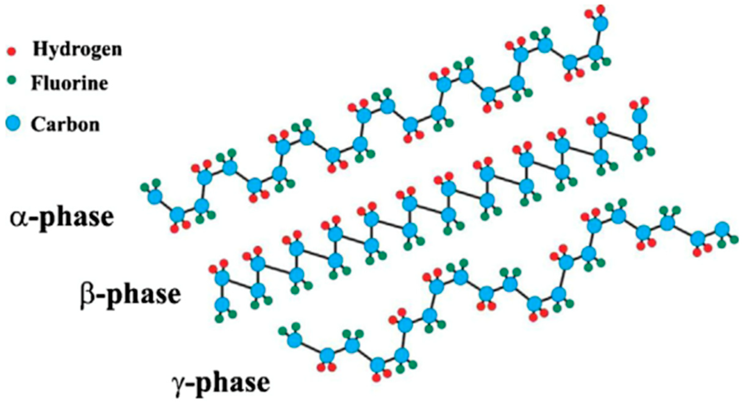
3.4. Organic Polymer Materials

Depending on their molecular structure and orientation, some carbon-based organic polymer substances have a piezoelectric effect. In 1969, Kawai first observed the piezoelectric effect in polyvinylidene fluoride (PVDF) polymers [68]. In contrast to inorganic piezoelectric materials, organic piezoelectric polymers are naturally lightweight, flexible, robust, and easy to fabricate into any shape, and cheap, making them advantageous for numerous applications [13,69].
The PVDF polymer exists in the α-phase, β-phase, γ-phase, and δ-phase, but only its β-phase exhibits spontaneous polarization; therefore, it shows advantageous electroactivity (piezoelectricity, ferroelectricity, and pyroelectricity). A high β-phase concentration renders PVDF polymer extremely sensitive to mechanical loads or strains. Therefore, the purpose of fabricating the polymer is to achieve as high a β-phase concentration as possible. Figure 4 depicts the polymeric structure of PVDF in the beta phase [70]. This alignment can be accomplished by mechanically stretching the material and then by using a poling procedure: applying a large static electric field at an elevated temperature.
Piezoelectric polymers show the mild strain coefficients and voltage coefficients, although they are considerably lower than their ceramic counterparts. Kanik et al. created kilometer-long PVDF micro- and nanoribbons using thermal fibre drawing but without using electrical poling [71]. The polar phase was still obtained as a result of the thermal drawing process at a high temperature and mechanical stretching stress. An individual 80 nm thick nanoribbon has an effective d33 value of 58.5 pC N−1. Two devices with a peak voltage of 60 V and a current of 10 μA were designed for energy harvesting and tapping sensors. Liu et al. employed a hollow cylindrical near-field electrospinning technique to create orientated PVDF fibres with a high β-phase [72]. Continuously stretching and releasing the nanofibers at 0.05% strain at 7 Hz frequency yielded a maximum voltage and current of 76 mV and 39 nA. Pan et al. utilized the same procedure to produce PVDF hollow fibres and obtained a voltage and power of 71.66 mV and 856.07 pW, respectively, which were greater than those obtained for solid PVDF fibres (45.66 mV, 347.61 pW) due to the increased elongation and Young’s modulus [73].
P(VDF-TrFE), a linear semicrystalline polymer, an abbreviation for the copolymer of PVDF and trifluoroethylene, was discovered. This polymer exhibits higher piezoelectricity due to its higher β-phase crystalline. Moreover, copolymer-based devices exhibit high sensitivity when they are used for biomedical sensing in wearable electronics due to their low permittivity and acoustic impedance. Yuan et al. presented a straightforward and inexpensive 3D-printing method to fabricate a flexible, multiple thin-layer PVDF-TrFE copolymer on a PDMS rugby ball framework (Figure 5) [74]. The fabrication method yielded an increase in the piezoelectric coefficient (d33 ~130 pC N−1), without the requirement of high-temperature annealing or complicated transfer procedures. In the low-frequency region, the rugby ball-structured piezoelectric energy harvester generated a high peak output voltage of 88.6 Vp-p and peak output power density of 16.4 mW cm−2 under a pressure of 0.046 MPa, which is about 22 times that of a flat-type harvester. In addition, they demonstrated the fabrication of a piezoelectric film using 3D printing technology and coated it with a pair of dislocated interdigital electrodes (ID), which allows for the harvesting of energy from cross-sectional areas with variable tilt-polarization [75]. According to the stated experimental findings, the ID tilt-polarized PVDF-TrFE film can generate a constant peak voltage of 73.5 V under a dynamic compression stress of 50 kPa at 1 Hz. Even while touching the film with a finger, eight LEDs might be illuminated immediately.

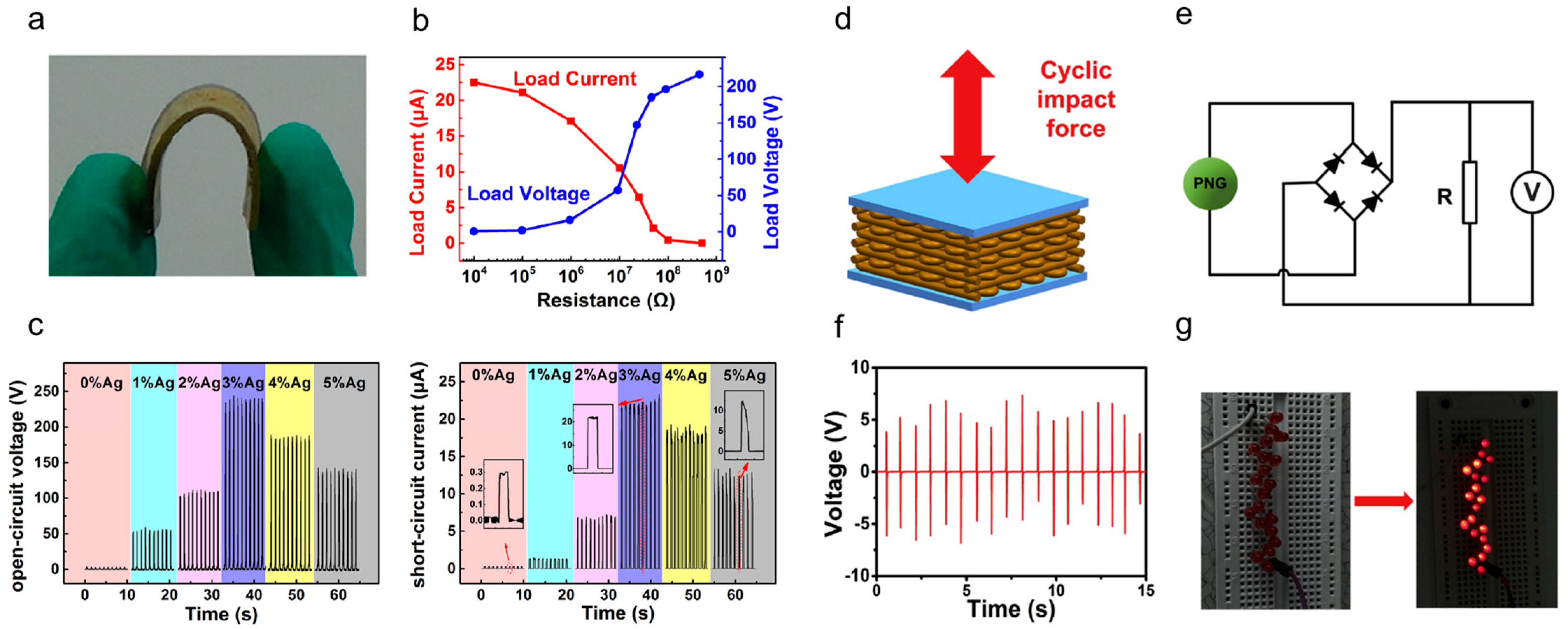
3.5. Composite Materials

In piezoelectric polymer composites, a brittle, hard-type filler with high piezoelectricity is inserted into a polymer matrix. This can combine the advantages of both materials, namely, the fillers’ high piezoelectric constant and coupling factor and the polymers’ flexibility. Apparently, fillers influence the comprehensive properties of the resulting piezoelectric nanocomposites. Although ceramics have an outstanding piezoelectric capability, their inherent fragility prevents their use in flexible devices. Despite these polymers’ considerable flexibility, their modest piezoelectric properties restrict their use in applications requiring a high energy density.
Huan et al. constructed a high-output piezoelectric nanogenerators (p-NG) device based on the piezoelectric Ag/(Na0.5K0.5)NbO3 particles and polydimethylsiloxane (PDMS) (Figure 6a) [76]. A p-NG device can generate approximately 1.13 mW power from motion and light up 9 commercial white LEDs without an external energy storage device (Figure 6b). When 3 mol% Ag content is incorporated into the system, the piezoelectric nanogenerator can generate a peak open-circuit voltage and short-circuit current of ~240 V and ~23 µA, respectively, under the external mechanical stress of 0.1 MPa. These values are over 70 times higher than the pure (Na0.5K0.5)NbO3/PDMS piezoelectric nanogenerators (Figure 6c). Wang et al. developed a piezoelectric nanogenerator using a 3D printing method to create a PNN-PZT/PDMS ceramic–polymer composite for electromechanical coupling (Figure 6d) [17]. The circuit diagram is shown in Figure 7e, where the load R is equivalent to twenty commercial red LEDs. When subjected to cyclic impacts from a hammer, the generator produced a maximum open-circuit output voltage of approximately 14 Vp-p (Figure 6f). This device was able to efficiently convert mechanical energy into electrical energy via electromechanical coupling and was capable of instantly illuminating over 20 commercial red LEDs without the need for a charge storage unit (Figure 6g).
Ponnamma et al. distributed BaTiO3 nanoparticles and hexagonal boron nitride (h-BN) nanolayers in the P(VDF-HFP) matrix to generate a nanocomposite [77]. The hybrid composite comprising 3 wt% BaTiO3 and 1 wt% h-BN outperformed the separate P(VDF-HFP)/BaTiO3 and P(VDF-HFP)/h-BN nanocomposites with an output voltage of 2.4 V. The synergistic effect of fillers created by interactions between BaTiO3 nanoparticles and h-BN nanolayers improves the performance of piezoelectric nanocomposites. Alam et al. investigated a non-toxic flexible piezoelectric hybrid generator based on cellulose [78]. Using native cellulose microfiber and PDMS with multi-walled carbon nanotubes (MWCNTs) as a conducting filler, the hybrid generator was developed. It generated an open-circuit output voltage of 30 V and a short-circuit output current of 500 nA in response to repeated human hand-punching, which corresponds to a power density of 9.0 W/cm3 that could light a number of LEDs or electronic devices such as an LCD screen, calculator, or wristwatch.

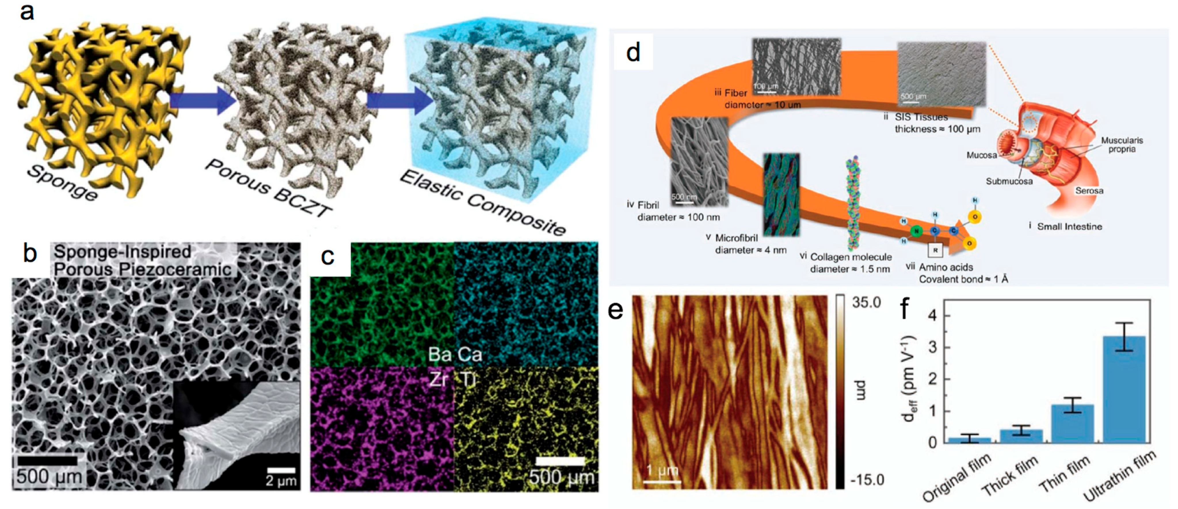
3.6. Bio-Inspired Piezoelectric Materials

Natural biological materials also display piezoelectric characteristics. Bio-inspired piezoelectric materials are considered as potential energy-harvesting substances because to their non-toxicity, biodegradability, and biocompatibility. The sea sponge, one of the simplest multicellular creatures, is composed of soft fibrils and hard skeletons arranged in a three-dimensional porous structure that provides exceptional elasticity and toughness. Wang et al. prepared sea-sponge-inspired (Ba,Ca)(Zr,Ti)O3 (BCZT) composites with ceramics and a PDMS matrix [79]. On the basis of a natural sea sponge, a 3D porous framework structure was developed. (Figure 7a–c). It was established that the mechanical and piezoelectric performances of the generator are far superior to those of a composite generator with randomly dispersed particles. Compressing the generator by 12% produced an output voltage, current density, and power density of 25 V, 550 nA/cm2, and 2.6 mW/cm2, respectively. This power density was sixteen times more than that of composites with randomly dispersed particles. By stretching, the composite piezoelectric generator generates an output voltage of ∼5 V, with a strain–voltage efficiency that is 30 times higher than those of the previous reports. Zhang et al. successfully separated the ultra-thin submucosal membrane of the small intestine using the van der Waals stripping method, revealing that biological tissues can exhibit significant piezoelectricity in a microscopic state, as shown in Figure 7d [80]. The ultrathin membrane still has high mechanical strength and can be used to prepare piezoelectric devices. The in-plane piezoelectric coefficient of the submucosa membrane, measured by the piezoresponse force microscope, is 4.1 pm/V, as shown in Figure 7e,f. The fabricated cantilever energy harvester shows 250 mV output during the vibration motion, revealing good biocompatible application prospects when only using natural materials.
Figure 7. (a) The microstructure of the piezoelectric sponge. (b) SEM image of the composite structure. (c) EDS mapping of the BCZT porous structure. Reproduced with permission. Copyright 2018, [79] Royal Society of Chemistry. (d) The structure of the submucosa of the small intestine. (e) The piezoresponse of the collagen fiber of the ultrathin submucosa membrane. (f) The piezoelectric coefficients of the submucosa membrane with different thickness. Copyright 2022, [80] Willey.
Nanoenergyadv 03 00005 g007
Biodegradable spider silk is a natural polymer fiber that has gained attention for its ecological sustainability, remarkable biomedical compatibility, high flexibility, large natural abundance, and great mechanical qualities. Karan et al. have successfully demonstrated the potential use of nature-driven spider silk without any further chemical treatment as an efficient piezoelectric nanogenerator for energy harvesting [81]. The fabricated bio-inspired piezoelectric nanogenerator can obtain a high output voltage (21.3 V) and current (0.68 μA) with a maximum instantaneous power density of 4.56 μW/cm2 and an energy conversion efficiency of 66%, respectively, through simple mechanical or biomechanical activities. Ghosh et al. developed a piezoelectric nanogenerator based on fish swim bladder, which is a waste product in fish processing. This nanogenerator consisted of highly ordered, self-aligned, natural collagen nanofibrils and could convert the compressive stress of a human finger (1.4 MPa) into electricity [82]. The resulting open-circuit voltage, short-circuit current, and instantaneous output power was 10 V, 51 nA, and 4.15 μW/cm2, respectively, which was sufficient to light 50 commercial blue LEDs.

3.7. Piezoelectret Foams

In the field of vibration energy harvesting, researchers have increasingly explored the potential of cellular polymer foam material to exhibit piezoelectric-like behavior [83]. The piezoelectret foam, also known as ferroelectret foam, is referred to as an electret effect; it is a dielectric material that contains a permanent electric charge. While these materials are ferroelectret, as opposed to traditional ferroelectric piezoelectric materials, they exhibit piezoelectric-like behavior. Because of the structure’s permanently charged internal voids, ferroelectret foam exhibits piezoelectric behavior. During the fabrication of this material, a polarization process results in the deposition of charge, which subsequently becomes trapped within the voids. When the material is subjected to mechanical or electrical stimuli, the charged voids behave as macroscopic dipoles, giving rise to similar properties to those of piezoelectric materials.
Wang et al. fabricated a porous layered piezoelectret comprising a single layer of fibrous porous PTFE (fPTFE) laminated between two dense skin layers of fluorinated ethylene propylene (dFEP) using the hot-pressing method at a temperature of ≈285 °C and pressure of ≈5 Mpa; then, it was further metalized and corona-poled [84]. The layered film electret generator produced a maximum peak power density output of approximately 31.4 μW cm−2 when connected to a 40 MΩ load. In addition, we demonstrated the use of the electret generator as a self-powered sensor for human breathing. Pondrom et al. further studied the stacked type of piezoelectret foam harvesters operating in ‘33’-mode to enhance energy-harvesting performance [85]. It was reported that the 20-layer stack of piezoelectret foam compressed harmonically at resonance (124.4 Hz) with 0.5 g of acceleration can charge a capacitor from 1 mF to 1.2 V in 45 min. For an optimal load resistance of 650 k, it could produce an output of around 3.8 mW g−2.
Zhang et al. produced a ferroelectric nanogenerator by employing a layered structure of fluorinated ethylene propylene (FEP) films with wide voids between them serving as tunneling barriers [86]. They obtained a better voltage coefficient of g31 = 3 Vm N−1, equivalent to d31 = 32 pC N−1, in the transverse direction. This high voltage coefficient, obtained due to the lower permittivity of this material system as compared with the PVDF of around g31 ≈ 0.2, shows a great application potential for energy harvesting. A compact EH was established that measures 3 × 5 × 8 mm3 and generated an output power of 50 μW. The device has a seismic mass of 0.09 g and operates at an acceleration of 1 g. Table 2 presents the main advantages, drawbacks, and potential applications of these micro-power generators.

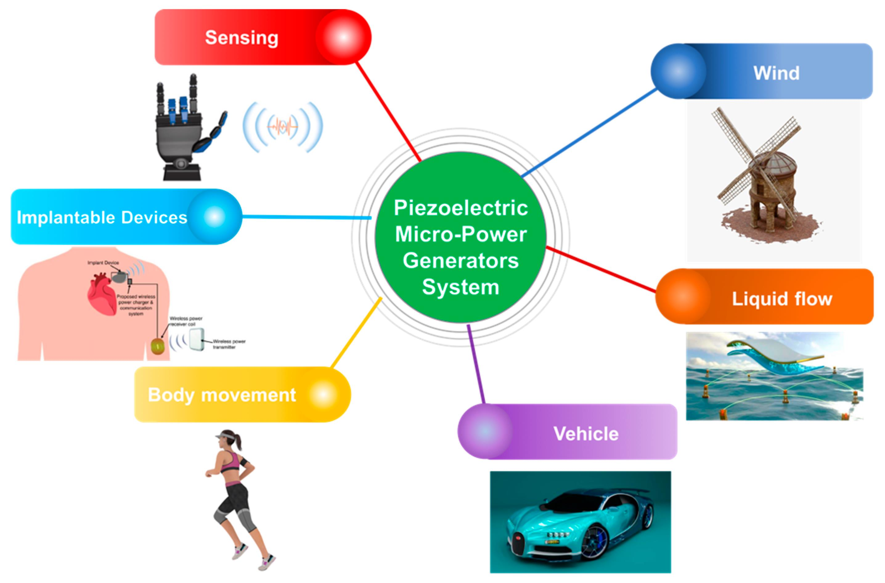
4. Applications of Piezoelectric Micro-Power Generators

The voltage generated by an energy harvester exhibits random variations with dual-polarity voltage peaks, which can be attributed to the stochastic characteristics of the input vibration source. To obtain an effective power output, it is necessary to convert random variation voltage to DC voltage with a single polarity and controllable voltage amplitude. Piezoelectric nanogenerators (PENGs) can be used to generate electrical power, which can be stored for extended periods and used to power various devices. To accomplish this, a bridge rectifier is typically used to convert the AC output of the PENG into DC, which is then used to charge a capacitor [87]. Once the capacitor has been charged to a sufficient level, it can be connected to an external storage device for the long-term storage of electrical energy. PENGs have been employed in a variety of applications, including self-powered systems for smart homes, as well as deformation detection and human-motion monitoring.

4.1. Piezoelectric Micro-Power from Wind

Recently, many researchers tried to harvest wind energy using flexible piezoelectric flags. In 2013, Kim et al. first investigated the flapping dynamics of an inverted flag to better meet the requirements of energy harvesting [88]. Orrego et al. then studied the wind-energy-harvesting performance of inverted piezoelectric flags in controlled and uncontrolled wind conditions [89]. The inverted flag configuration offers several advantages, including the ability to generate sustained power across a wide range of wind speeds, tune resonance by adjusting bending stiffness, and self-oscillate at desired wind speeds by adjusting length. According to a report, piezoelectric flags measuring 60 mm and 100 mm in length produced a peak power output of 1–5 mW/cm3 at a 5–9 m/s wind speed and 0.1–0.4 mW/cm3 at a 2.5–4.5 m/s wind speed, respectively.
Zhang et al. created a rotational piezoelectric-energy harvester that harvests wind energy via the impact-induced vibration of a piezoelectric (PVDF) beam [90]. Figure 8a depicts a wind energy harvester. Three piezoelectric cantilever beams are integrated in an exterior casing. To boost energy harvesting conversion efficiency, a flexible piezoelectric material (PVDF) with a significant deformation response and a wide range of vibration frequencies are used as the energy harvesting element. On opposite ends of the rotating shaft, a fan blade and a turntable are affixed. The turntable’s blade count is three. However, it is malleable. The harvester’s functioning is straightforward. The fan blade rotates as air rushes past the harvester, and the turntable is driven by the revolving shaft. At this point, the turntable contacts the piezoelectric (PVDF) beam, causing periodic oscillations in the beam. As a result, an electric field is created. A maximum rms voltage of 160.2 V and a maximum output power of 2566.4 μW were obtained at the wind speed of 14 m/s.
Gao et al. introduced a self-assembled film of piezoelectric monolayer BaTiO3, created using a topochemical conversion procedure to produce BaTiO3 micro-platelets [91]. An interfacial technique was then used to assemble the oriented monolayer BaTiO3 film, which was subsequently spin-coated with polydimethylsiloxane (PDMS) to create a flexible piezoelectric generator, as shown in Figure 8b. The generator was tested for its output performance by demonstrating its application in harvesting wind energy. It was fixed onto a support and tapped by a paddle attached to one of the blades of a windmill rotating in the wind. The maximum output power of the piezoelectric generator reached 0.021 mW at an external load of 80 MW, which was sufficient to light an LCD, as shown in Figure 8c. The generator produced voltage and current outputs of up to 2.3 V and 96 nA, respectively. Table 3 summarizes various windmill-style piezoelectric harvesters, including their transducer type, generator material, dimensions, wind speed, and output power.

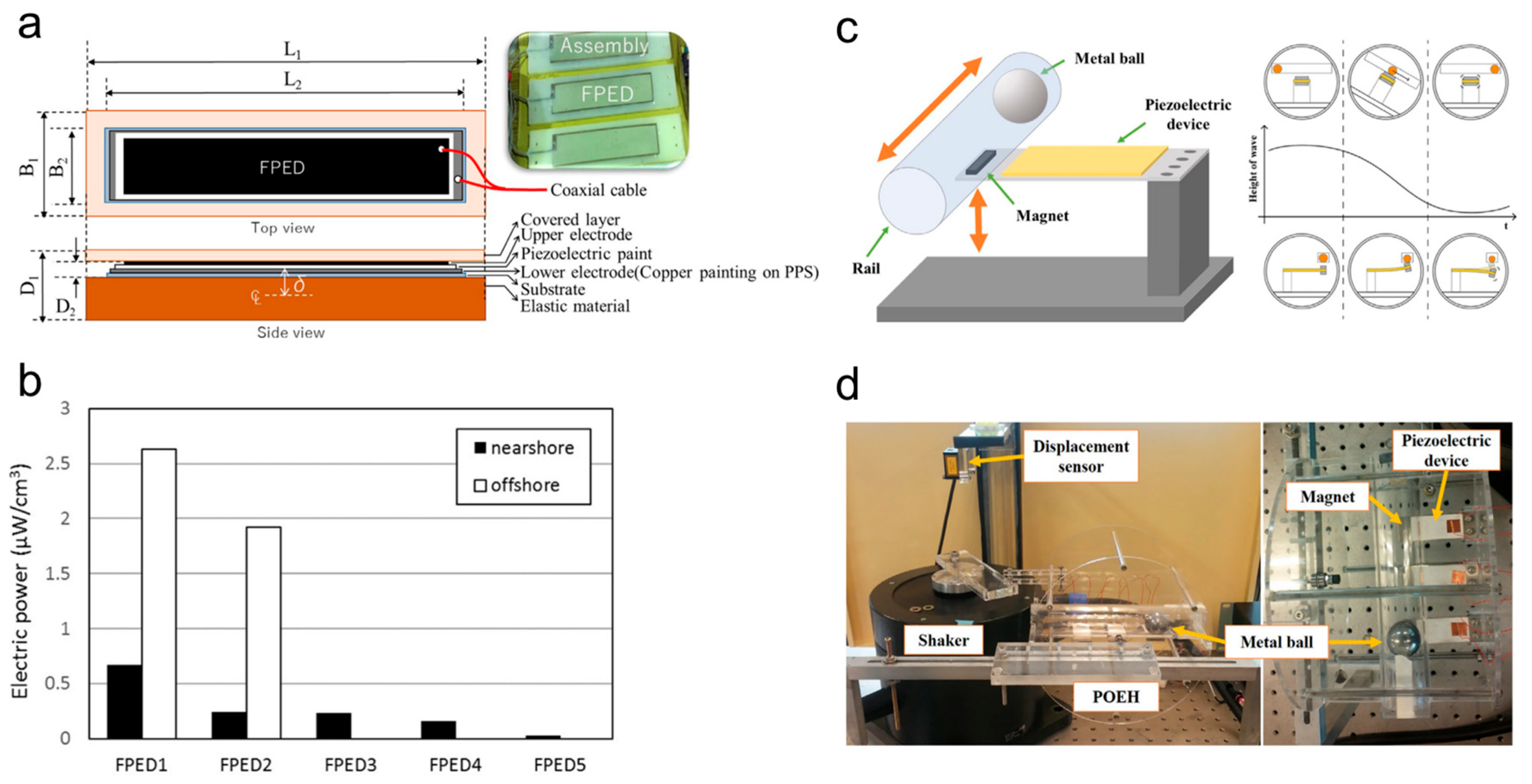
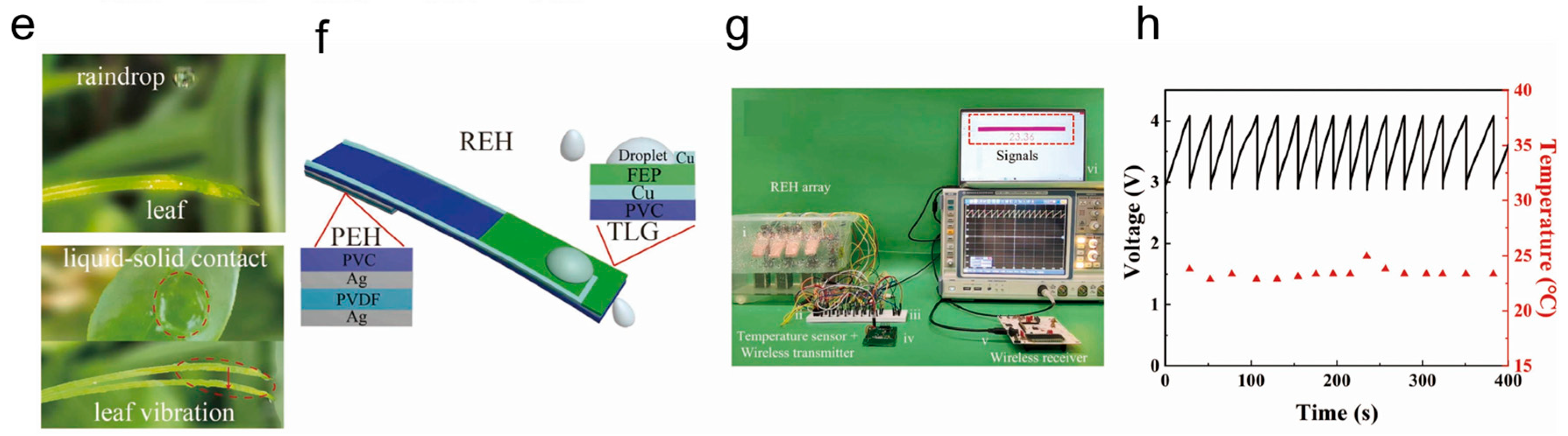
4.2. Piezoelectric Micro-Power from Liquid Flow

Oceans cover 70% of the Earth’s surface, making wave energy an appealing option for energy harvesting. Notably, the ocean is not only abundant in natural resources such as oil and gas, but also in potential energy, which might be an even more benign source of energy than wind [97]. It has been estimated that ocean wave energy can provide as much as 885 TWh of total electricity [98].
Taylor et al. developed an energy harvesting system that converts kinetic energy into electricity to power remote sensors and robots using a slender strip of a PVDF piezoelectric polymer that mimics the movement of an eel in water [99]. In non-turbulent flow, the system’s bluff body periodically releases vortices on both sides, generating eddy currents that cause the strip to oscillate and deform, producing an AC voltage output. The strip consists of three layers, with a central inactive layer and two active layers of piezoelectric material bonded to each side. The system includes five of these strips, each measuring 132 cm in length, 15.24 cm in width, and 400 µm in thickness. At a flow rate of 1 m/s, the system can generate 1 W of power with an energy conversion efficiency of approximately 33%. The system can charge batteries or capacitors of remote sensor arrays and robot groups, thereby extending their mission life as long as there is flowing water in the ocean.
Mutsuda et al. devised a flexible piezoelectric device (FPED) for harvesting wave energy [100]. Figure 9a depicts the FPED. Using a spray nozzle, the piezoelectric PVDF film was coated on an elastic substrate with electrodes. The elastic material is exceptionally resilient and can survive after experiencing the tremendous bending and deterioration induced by ocean waves and currents. Figure 9b depicts the output of an FPED with dimensions of 200 mm (length), 60 mm (wide), and 5 mm (thickness) for an onshore and offshore test. The FPED’s power density can reach 2.6 μW/cm3. As shown in Figure 9c, Hwang et al. reported a PEH based on sway motion. This is primarily composed of a piezoelectric cantilever and a magnet [101]. A catheter with a metal ball is positioned above the magnet and functions at the module’s tip. The test bench is seen in Figure 9d, and the system was evaluated using a setting that simulates ocean waves. The maximum output voltage for a device with dimensions of 3.8 cm × 1.9 cm × 0.2 cm at a simulated wave frequency of 0.5 Hz is 21.1 V, and the power density is 47.85 μW m−3.
Utilizing the synergy between the inherent contact electrification of the raindrops and the piezoelectric effect will generate considerable energy. Xu et al. designed a leaf-mimic rain energy harvester, which is composed of a PVDF-based piezoelectric energy generator (PEG) and an FEP-based triboelectric energy generator (FEG), as shown in Figure 9e,f [102]. When raindrops fall on the surface of the device, the contact electrification energy is first collected by the FEG. Then, the induced vibration energy will be harvested by the PEG. Under synergy, the raindrop energy harvester is able to generate a high-output power density of 82.66 Wm−2, which is enough to supply the power needed to run a temperature sensor, as shown in Figure 9g,h.

4.3. Piezoelectric Micro-Power from Vehicles

The dissipation of energy in various vehicle components, particularly the suspension system, is a significant factor affecting the fuel efficiency of automobiles. A total of 10–16% of the fuel energy is utilized to propel the vehicle, which overcomes opposition from road friction and air drag, whilst the majority is lost as heat and mechanical energy [103]. Researchers are investigating the viability of energy harvesting from the vehicle suspension system and tires, which contain rich vibration and force profiles, as a means of utilizing the unused energy of automobiles.
Singh et al. investigated the use of an inertial vibrating energy harvester as a power source for a tire-mounted sensor module [104]. They developed a piezoelectric device using a bimorph cantilever with high-density PZT-ZNN piezoelectric layers and two mechanical stoppers to minimize mechanical strain and generate electricity from the radial vibrations of the tire. During the design process, the team prioritized broadband operation, low weight, and small size. The resulting beam has dimensions of of 25 × 5 × 0.4 mm3 and a tip mass of 11.4 g. During testing, the device produced 31 μW of power across a resistive load of 330 kΩ at 80 Hz and 0.4 g RMS base excitation.
Hong et al. developed a piezoelectric harvester designed for use on roads, called a road-capable piezoelectric harvester (RCPH) [105]. The resulting output voltage was measured to be 18 Vmax, with an output power of 1150 mWmax and a power density of 1.15 mW/cm2, when a load resistance level of 910 Ω was applied. The electrical energy generated by the 1 cm landfilled module was sufficient to power 4 delineators for 40 seconds on a test route. This suggests that the piezoelectric modules could be connected to an emergency lighting system to provide the continuous electricity generated by passing vehicles, making this technology suitable for use on real roads.
Wang et al. developed a PZT-based energy harvester on the jet engine that harnesses the rotational mechanical energy for powering wireless engine monitors, as shown in Figure 10a [106,107,108]. The designed high-efficiency compressive-mode piezoelectric energy harvester generates energy during the periodic changes in gravity induced by the rotation motion of the engine. The energy harvester demonstrated a high-power output (78.87 mW), a broad bandwidth (22.5 Hz), and strong reliability (2100 RPM), as shown in Figure 10b,c.

4.4. Piezoelectric Micro-Power from Body Movement

Kim et al. created a wearable piezoelectric generator, developed using boron nitride nanosheets, to convert mechanical energy from human body movement into electrical energy (Figure 11a) [109]. The generator was capable of producing a peak output voltage of 22 V and output power of 40 μW under a periodic mechanical push force of 80 kg with a power density of 106 μW/cm3. Moreover, the generator was attached to different human body parts and produced output voltages of 2.5 V at the foot, 1.98 V at the elbow, 0.48 V at the neck, 0.75 V at the wrist, and 1.05 V at the knee in response to differential human movement.
Jung et al. constructed a a piezoelectric generator based on polyvinylidene fluoride (PVDF) that can harvest low-frequency biomechanical energy from body movement for use in wearable devices (Figure 11b) [110]. The device was able to generate an output power density of 3.9 mW/cm2, which is sufficient to power 476 LED bulbs. During testing, the generator produced an average output voltage of 45 V and an output current of 225 μA at 35 Hz. The researchers also incorporated the technology into a shoe insole and a watch band. The insole generator generated an average output voltage of 14 V and an average output current of 18 μA, while the watch generator produced an average output voltage of 22 V and an average output current of 50 μA while running. Park et al. presented a nontoxic ultra-flexible piezoelectric energy harvesters based on piezoelectric composite fibers, in which lead-free (Ba0.85Ca0.15)(Ti0.90Zr0.10)O3 (BCTZ) nanoparticles (NPs) are dispersed in poly(vinylidene fluoride-co-trifluoroethylene) (P(VDF-TrFE)) fibers using a facile electrospinning process (Figure 9c) [111]. Particularly, post-treatments, including post-crystallization and extra-poling, were utilized to improve the piezoelectric performance of the piezoelectric composite fiber-based membrane. Following post-treatments, the VOC and ISC produced by the piezoelectric composite fiber membrane rose by 6.6 and 15.7 times, respectively. Regarding the post-treated piezoelectric composite fiber membrane containing 20 wt% BCTZ NPs, the output voltage and current reached 36.5 V and 1.09 μA, respectively, much higher than the previously reported results for lead-free, piezoelectric composite, fiber-type energy harvesters.
Shi et al. fabricated a flexible PENG from electrospun fiber mats containing 15 wt% BaTiO3 NPs, 0.15 wt% graphene nanosheets, and PVDF (Figure 11d) [112]. During the finger pressing-releasing operation, the PENG created a peak voltage of 112 V, which powered an electric timepiece and illuminated 15 LEDs. In addition, it gathered energy from human movements such as finger tapping, wrist flexion, and foot stepping. Under the conditions of wrist flexion and finger tapping, the output voltage reached 7.7 V and 7.5 V, respectively. When the PENG was placed under the foot hell and toe, the PENG generated a maximum voltage of 7.8 V and 2.8 V, respectively. The heel exerted greater pressure than the toe, resulting in an increased output voltage. Through an appropriate structural design, the hard ceramic block can also be used as a wearable device for energy harvesting. Inspired by two branches of the hyoid bone of the woodpecker, Wang et al. designed a two-layer band piezoelectric energy harvester for powering smartwatches and wristbands via the movement mode and the impact mode, as shown in Figure 11e,f [113,114]. The energy harvester is assembled by integrating multiple PZT ceramic bulks onto the watchband. The maximum output power can reach 12.25 mW during normal walking, while the maximum output power can reach 15.4 mW in impact mode, which can meet the basic working requirements of watches and bracelets.

4.5. Implantable Devices

Piezoelectric energy harvesting has emerged as a promising option to eliminate the need for batteries in wearable electronics, thanks to the development of innovative methods and materials, and advancements in low-power electronic technology. In addition, implantable active medical devices such as cardiac pacemakers, cardioverter defibrillators, cardiac monitors, and neurological brain stimulators can also benefit from this technology [115]. By incorporating energy harvesting into these devices, the need for later maintenance operations can be significantly reduced, which can, in turn, lower the associated costs and minimize potential risks. This demonstrates the potential of piezoelectric energy harvesting in powering a range of devices, from portable electronics to implantable medical devices.
Jiang et al. built a flexible piezoelectric array for ultrasonic energy harvesting using a PZT/epoxy composite [116]. Under ultrasonic excitation, the designed apparatus generated a constant power output. There was an output voltage of 2.1 Vp-p and a current of 4.2 µA. The produced electricity might be stored in capacitors and utilized to power commercial LEDs. In vitro experiments revealed that the output signals exhibit a weak attenuation of about 15% after penetrating a simulating implanted tissue with 14 mm thickness.
Ansari et al. exploited heartbeat vibrations to power a lead-free pacemaker using a fan-folded structure of piezoelectric beams [117]. Multiple piezoelectric beams were piled on top of one another. The created energy-collecting gadget, which measured at 2 cm × 0.5 cm × 1 cm, could operate at extremely high frequencies. The fan-folded shape allowed for the reduction in frequency to the appropriate levels, and the power production was more than 10 µW, which was sufficient to power a lead-free pacemaker without external power.
Deterre et al. introduced a very compact piezoelectric energy harvester that generates electricity from normal blood pressure fluctuations to operate a pacemaker without leads [118]. The gadget was a spiral-shaped piezoelectric beam contained within an ultra-flexible package with a 10 μm diaphragm. The diameter of the harvester was 6 mm and its volume was 21 mm3. The experimental results revealed that a gadget with an optimal design generates a power density of 3 μJ cm−3 per heartbeat. Hong et al. developed a wood-templated transmuscular piezoelectric energy harvester that transfers the ultrasonic energy to power implantable wireless devices, as shown in Figure 12a [119]. Using wood as a template, unidirectionally aligned layered piezoelectric ceramics are obtained, and the flexibility of the device can be improved by adding polymers into the matrix. Under the ultrasonic stimulation conducted ex vivo, the wood-templated piezoelectric ultrasonic energy harvester exhibits a maximum open-circuit voltage of 21 V, and a short-circuit current of 2 mA output. While in vivo, the device will generate 4.5 V output, which can supply power for most implants, as shown in Figure 12b,c.

4.6. Piezoelectric Micro-Power Generator for Sensing

Piezoelectric materials have applications beyond energy harvesting, including self-powered sensing. The piezoelectric equation provides a quantitative relationship between the electrical output of the material and the applied strain or stress, which means that piezoelectric nanogenerators (PENGs) can be used as sensors to detect and measure stimuli such as pressure, vibration, acceleration, and acoustic waves. Unlike resistive or capacitive sensors, PENGs are positive devices for which batteries are not required.
As depicted in Figure 13a, according to Deng et al., a robotic arm could be remotely controlled by combining PENG sensing, signal transmission, and executive control [120]. The functional layer of the PENG utilized cowpea-structured PVDF/ZnO nanofibers, which increased mechanical flexibility and electrical output, allowing the sensors to respond quickly and sensitively to bending angle motions. When the sensors were attached to the finger knuckle, they converted the bending action of the finger into electrical impulses, allowing the robotic hand to replicate the same gesture as a human hand through a peripheral circuit module.
To achieve a personalized healthcare system, it is crucial to monitor vital signs. This allows for an accurate assessment of an individual’s physiological state and provides a baseline for identifying related medical conditions. Hong et al. developed a flexible piezoceramic composite sensor that utilizes a kirigami structure to detect joint motions and differentiate between different motion modes (Figure 13b) [121]. They employed a modified, template-assisted, sol-gel technique for the fabrication of the composite, and used a two-dimensional honeycomb piezoceramic kirigami as the main sensor element. The developed kirigami structure improves the piezoelectric characteristics and provides high-dimensional anisotropy. This technique has potential applications in the development of flexible electronics for health-monitoring devices, as well as the prevention and rehabilitation of upper-extremity musculoskeletal problems.
Signals related to the biomechanics of the human body could also provide vital medical information. Yao et al. recently developed a wearable piezoelectric nanogenerator (PENG) that can measure biomechanical signals related to the human body, providing valuable medical information. The PENG is made of 3D-printable piezoelectric nanocomposites manufactured using additive manufacturing techniques and has exceptional responsiveness and compliance [122]. To measure punch force during boxing activities, the researchers embedded the PENG lattice with microarchitectures and placed it inside a boxing glove. The signals generated by the PENG were transmitted to a terminal using an embedded WiFi module, as shown in Figure 13c. By analyzing the electrical signal collected from the specific PENG electrode, the researchers were able to plot the spatial distribution of force corresponding to a direct blow or a right hook on the receiving device. This application demonstrated the PENG’s ability to monitor the hand’s reaction force during boxing activities. In another study, Fuh et al. successfully demonstrated foot pressure mapping using a sensor array composed of PENGs [123]. The researchers used 2D electrode patterns and thin films of piezoelectric polymers to create complex 3D piezoelectric microsystems. The self-powered fabricated device is capable of significantly boosting piezoelectric output and can be directly applied to foot pressure measurement and human motion monitoring. When the device was subjected to pressure at various locations and levels, it exhibited a variety of performances.
Existing piezoelectric elements are fabricated in fixed geometries such as planar sheets, disks, or tubes within strict laboratory environment conditions and high-quality substrates. They cannot conformally fit 3D free-form surfaces, which significantly confines the practical application value of piezoelectric films. Liu et al. developed a facile method to conformally fabricate piezoelectric thin films onto 3D free-form objects, as shown in Figure 13e [124]. By using flame treatment, the surface energy is significantly reduced, and the films can easily be assembled onto any surface. Thus, the piezoelectric thin films can be fabricated onto any surface on-site, for example, the wing of aircraft, for structural health real-time monitoring, as shown in Figure 13f.

5. Conclusions and Future Perspectives

A detailed review of the recent progress regarding the use piezoelectric materials for various applications in piezoelectric micro-power generators has been presented in this article. Despite encouraging results from the research, only a few piezoelectric goods have been commercialized, with others are still in the research and development stages. New materials have been preoduced to meet the demands of certain applications. For example, the successful use of a high-performance flexible PMNT thin film to power brain stimulators, which consume far more energy than cardiac pacemakers, was recently proven. Furthermore, new materials with improved qualities are projected to find use in a variety of industries in the near future. The discovery of materials with high Curie temperatures, for example, will enable the use of piezoelectric energy harvesters in heat-transfer applications involving fluid movement. Furthermore, it is expected that the recent increase in interest in piezoelectric energy harvesting will expand as novel piezoelectric materials and untapped vibration sources are discovered.
The development and application of wearable and implantable PENGs involve multiple disciplines, such as physics, chemistry, material science, computer science, mechanical engineering, electrical engineering, and bioengineering. To ensure that each field is handled with maximum expertise, interdisciplinary collaboration among scientists is essential. Moreover, it is crucial to establish strong partnerships between academia and industry to facilitate the transition of these devices from the laboratory to commercially viable products, ultimately leading to industrialization.
Piezoelectric energy harvesters (PEHs) have been extensively studied for the more effective capturing of nano-micro energy in the environment, including harvesting micro-energy from human body for flexible wearable electronics and implantable biomedical electronics, but there are still certain challenges before their industrialization or final clinical applications.
Piezoelectric energy harvesters (PEHs) need to be environmentally friendly and highly biocompatible when entering the stage of practical applications. Existing PEHs with an appreciable energy output are usually based on lead-based materials such as PZT ceramics. However, the use of lead-containing materials has been strictly restricted by the Restriction of Hazardous Substances Directive (RoHS) due to their biological toxicity. Therefore, one challenge is continually developing lead-free piezoelectric materials with piezoelectric performances that are comparable to lead-based piezoelectric ceramics. Currently, progress has been made toward the achievement of high piezoelectricity through the use of KNN-based piezoelectric ceramics, molecule crystals, and even PVDF-based polymers; however, much still remains to be done [125]. We may choose to completely isolate the PEHs from the organism through encapsulation or packaging; however, this could bring new challenges, as the packaging material must be inert enough that there is no concern that it will provide additional biological toxicity, and strong enough to resist environmental erosion. In addition, an excessive packaging volume or inappropriate packaging processes will affect the sensitivity and energy conversion efficiency of piezoelectric devices.
In the future, hybrid energy harvesting devices will emerge; for example, a magnetoelectric harvester could be used for the simultaneous harvesting of both magnetic field energy and mechanical energy. Piezoelectric devices have energy-harvesting potential as they can generate electricity from surrounding vibrations and strain. Magnetic domains in a magnetostrictive ferromagnetic material spin under an external magnetic field and expand appropriately to drive a load, while external mechanical stress also changes the magnetic characteristics due to the inverse magnetostriction effect. Magnetostrictive devices can also harvest energy by generating a current in a wire coiled around the material in response to a change in magnetic flux or an external stress and strain. Furthermore, ferromagnetic/piezoelectric-composited magnetoelectric harvesters are more efficient in capturing both magnetic field energy and mechanical energy via magneto–mechano–electric (MME) coupling mechanism, which will be an emerging technique for powering wireless Internet of Things devices in the future. No doubt, one hybrid energy harvester incorporating multiple mechanisms, such as the electromagnetic effect, triboelectric effect, thermoelectric effect, and photoelectric effect, can better maximize the captured energy in a complex environment than a single-mechanism-based PEH. However, it is still challenging to effectively integrate multiple mechanisms in one structure.
Energy harvesting has significant implications for the growth of IoTs and the creation of new applications in practically every industry, including smart homes, smart cities, smart factories, health and environmental monitoring, and intelligent transportation. It is an essential component in the development of an autonomous and mobile technology that can operate for extended periods of time without requiring battery charges. As a result, it leads to cost savings by deferring battery replacement or not using batteries at all. The rise in consumer electronic devices such as computer peripherals, electronic bracelets, watches, and surveillance cameras is driving the demand for energy harvesting. The rise in wearable sensors is also creating new potential for energy collection. By developing sensors and self-sufficient batteries, it is envisaged that technological breakthroughs in materials, device integration, and manufacturing methods in the piezoelectric energy sector will play a major part in resolving the global energy issue. Energy harvesting in the automotive industry is steadily increasing, particularly in the electric car market. This demonstrates that energy collecting has limitless future possibilities for meeting the rising energy demands.
Finally, we hope this review accurately portrayed the current growth in the piezoelectric energy harvesting field and provided enough research coverage for the many research organizations working in this exciting field.

Author Contributions

Conceptualization, Z.W., S.L. and S.D.; writing—original draft preparation, Z.W. and S.L. writing—review and editing, Z.Y. and S.D.; supervision, Z.Y. and S.D.; project administration, S.D.; funding acquisition, S.D. All authors have read and agreed to the published version of the manuscript.

Funding

This work was supported by the National key research and development program of China (Grant Nos. SQ2022YFB3200003 and SQ2022YFB3200216).

Conflicts of Interest

The authors declare no conflict of interest.

References

  1. Brown, T.W.; Bischof-Niemz, T.; Blok, K.; Breyer, C.; Lund, H.; Mathiesen, B.V. Response to ‘Burden of proof: A comprehensive review of the feasibility of 100% renewable-electricity systems’. Renew. Sustain. Energy Rev. 2018, 92, 834–847. [Google Scholar] [CrossRef]
  2. Davis, S.J.; Lewis, N.S.; Shaner, M.; Aggarwal, S.; Arent, D.; Azevedo, I.L.; Benson, S.M.; Bradley, T.; Brouwer, J.; Chiang, Y.-M. Net-zero emissions energy systems. Science 2018, 360, eaas9793. [Google Scholar] [CrossRef] [PubMed] [Green Version]
  3. Sachs, J.D.; Schmidt-Traub, G.; Mazzucato, M.; Messner, D.; Nakicenovic, N.; Rockström, J. Six transformations to achieve the sustainable development goals. Nat. Sustain. 2019, 2, 805–814. [Google Scholar] [CrossRef]
  4. Parinov, I.A.; Cherpakov, A.V. Overview: State-of-the-Art in the Energy Harvesting Based on Piezoelectric Devices for Last Decade. Symmetry 2022, 14, 765. [Google Scholar] [CrossRef]
  5. Devabhaktuni, V.; Alam, M.; Depuru, S.S.S.R.; Green, R.C., II; Nims, D.; Near, C. Solar energy: Trends and enabling technologies. Renew. Sustain. Energy Rev. 2013, 19, 555–564. [Google Scholar] [CrossRef]
  6. Jiaqiang, E.; Ding, J.; Chen, J.; Liao, G.; Zhang, F.; Luo, B. Process in micro-combustion and energy conversion of micro power system: A review. Energy Convers. Manag. 2021, 246, 114664. [Google Scholar]
  7. Truitt, A.; Mahmoodi, S.N. A review on active wind energy harvesting designs. Int. J. Precis. Eng. Manuf. 2013, 14, 1667–1675. [Google Scholar] [CrossRef]
  8. Wei, C.; Jing, X. A comprehensive review on vibration energy harvesting: Modelling and realization. Renew. Sustain. Energy Rev. 2017, 74, 1–18. [Google Scholar] [CrossRef]
  9. Cai, M.; Yang, Z.; Cao, J.; Liao, W.-H. Recent advances in human motion excited energy harvesting systems for wearables. Energy Technol. 2020, 8, 2000533. [Google Scholar] [CrossRef]
  10. Chou, S.; Yang, W.; Chua, K.; Li, J.; Zhang, K. Development of micro power generators—A review. Appl. Energy 2011, 88, 1–16. [Google Scholar] [CrossRef]
  11. Zaszczyńska, A.; Gradys, A.; Sajkiewicz, P. Progress in the applications of smart piezoelectric materials for medical devices. Polymers 2020, 12, 2754. [Google Scholar] [CrossRef]
  12. Covaci, C.; Gontean, A. Piezoelectric energy harvesting solutions: A review. Sensors 2020, 20, 3512. [Google Scholar] [CrossRef]
  13. Liu, H.; Zhong, J.; Lee, C.; Lee, S.-W.; Lin, L. A comprehensive review on piezoelectric energy harvesting technology: Materials, mechanisms, and applications. Appl. Phys. Rev. 2018, 5, 041306. [Google Scholar] [CrossRef] [Green Version]
  14. Yang, Z.; Zhou, S.; Zu, J.; Inman, D. High-performance piezoelectric energy harvesters and their applications. Joule 2018, 2, 642–697. [Google Scholar] [CrossRef] [Green Version]
  15. Sezer, N.; Koç, M. A comprehensive review on the state-of-the-art of piezoelectric energy harvesting. Nano Energy 2021, 80, 105567. [Google Scholar] [CrossRef]
  16. Aksel, E.; Jones, J.L. Advances in lead-free piezoelectric materials for sensors and actuators. Sensors 2010, 10, 1935–1954. [Google Scholar] [CrossRef]
  17. Wang, Z.; Yuan, X.; Yang, J.; Huan, Y.; Gao, X.; Li, Z.; Wang, H.; Dong, S. 3D-printed flexible, Ag-coated PNN-PZT ceramic-polymer grid-composite for electromechanical energy conversion. Nano Energy 2020, 73, 104737. [Google Scholar] [CrossRef]
  18. Zhang, S.; Yu, F. Piezoelectric materials for high temperature sensors. J. Am. Ceram. Soc. 2011, 94, 3153–3170. [Google Scholar] [CrossRef]
  19. Gao, X.; Yang, J.; Wu, J.; Xin, X.; Li, Z.; Yuan, X.; Shen, X.; Dong, S. Piezoelectric actuators and motors: Materials, designs, and applications. Adv. Mater. Technol. 2020, 5, 1900716. [Google Scholar] [CrossRef]
  20. Wu, J.; Gao, X.; Chen, J.; Wang, C.M.; Zhang, S.; Dong, S. Review of high temperature piezoelectric materials, devices, and applications. Acta Phys. Sin. 2018, 67, 207701. [Google Scholar]
  21. Zhao, Z.; Dai, Y.; Dou, S.; Liang, J. Flexible nanogenerators for wearable electronic applications based on piezoelectric materials. Mater. Today Energy 2021, 20, 100690. [Google Scholar] [CrossRef]
  22. Hu, D.; Yao, M.; Fan, Y.; Ma, C.; Fan, M.; Liu, M. Strategies to achieve high performance piezoelectric nanogenerators. Nano Energy 2019, 55, 288–304. [Google Scholar] [CrossRef]
  23. Li, X.; Sun, M.; Wei, X.; Shan, C.; Chen, Q. 1D piezoelectric material based nanogenerators: Methods, materials and property optimization. Nanomaterials 2018, 8, 188. [Google Scholar] [CrossRef] [PubMed] [Green Version]
  24. Xu, Q.; Wen, J.; Qin, Y. Development and outlook of high output piezoelectric nanogenerators. Nano Energy 2021, 86, 106080. [Google Scholar] [CrossRef]
  25. Muralt, P. Recent progress in materials issues for piezoelectric MEMS. J. Am. Ceram. Soc. 2008, 91, 1385–1396. [Google Scholar] [CrossRef]
  26. Tian, W.; Ling, Z.; Yu, W.; Shi, J. A review of MEMS scale piezoelectric energy harvester. Appl. Sci. 2018, 8, 645. [Google Scholar] [CrossRef] [Green Version]
  27. Safaei, M.; Sodano, H.A.; Anton, S.R. A review of energy harvesting using piezoelectric materials: State-of-the-art a decade later (2008–2018). Smart Mater. Struct. 2019, 28, 113001. [Google Scholar] [CrossRef]
  28. Li, L.; Xu, J.; Liu, J.; Gao, F. Recent progress on piezoelectric energy harvesting: Structures and materials. Adv. Compos. Hybrid Mater. 2018, 1, 478–505. [Google Scholar] [CrossRef]
  29. Salim, M.; Salim, D.; Chandran, D.; Aljibori, H.S.; Kherbeet, A.S. Review of nano piezoelectric devices in biomedicine applications. J. Intell. Mater. Syst. Struct. 2018, 29, 2105–2121. [Google Scholar] [CrossRef]
  30. Kapat, K.; Shubhra, Q.T.; Zhou, M.; Leeuwenburgh, S. Piezoelectric nano-biomaterials for biomedicine and tissue regeneration. Adv. Funct. Mater. 2020, 30, 1909045. [Google Scholar] [CrossRef] [Green Version]
  31. Kim, H.S.; Kim, J.-H.; Kim, J. A review of piezoelectric energy harvesting based on vibration. Int. J. Precis. Eng. Manuf. 2011, 12, 1129–1141. [Google Scholar] [CrossRef]
  32. Katzir, S. The discovery of the piezoelectric effect. In The Beginnings of Piezoelectricity; Springer: Berlin/Heidelberg, Germany, 2006; pp. 15–64. [Google Scholar]
  33. Jean-Mistral, C.; Basrour, S.; Chaillout, J. Comparison of electroactive polymers for energy scavenging applications. Smart Mater. Struct. 2010, 19, 085012. [Google Scholar] [CrossRef]
  34. Xu, S.; Wang, Z.L. One-dimensional ZnO nanostructures: Solution growth and functional properties. Nano Res. 2011, 4, 1013–1098. [Google Scholar] [CrossRef] [Green Version]
  35. Yang, Q.; Guo, X.; Wang, W.; Zhang, Y.; Xu, S.; Lien, D.H.; Wang, Z.L. Enhancing sensitivity of a single ZnO micro-/nanowire photodetector by piezo-phototronic effect. ACS Nano 2010, 4, 6285–6291. [Google Scholar] [CrossRef]
  36. Wang, Z.L. ZnO nanowire and nanobelt platform for nanotechnology. Mater. Sci. Eng. R Rep. 2009, 64, 33–71. [Google Scholar] [CrossRef]
  37. Wang, Z.L.; Song, J. Piezoelectric nanogenerators based on zinc oxide nanowire arrays. Science 2006, 312, 242–246. [Google Scholar] [CrossRef]
  38. Kim, H.; Kim, S.M.; Son, H.; Kim, H.; Park, B.; Ku, J.; Sohn, J.I.; Im, K.; Jang, J.E.; Park, J.-J. Enhancement of piezoelectricity via electrostatic effects on a textile platform. Energy Environ. Sci. 2012, 5, 8932–8936. [Google Scholar] [CrossRef]
  39. Kim, K.-H.; Kumar, B.; Lee, K.Y.; Park, H.-K.; Lee, J.-H.; Lee, H.H.; Jun, H.; Lee, D.; Kim, S.-W. Piezoelectric two-dimensional nanosheets/anionic layer heterojunction for efficient direct current power generation. Sci. Rep. 2013, 3, 2017. [Google Scholar] [CrossRef] [Green Version]
  40. Gao, M.; Wang, P.; Jiang, L.; Wang, B.; Yao, Y.; Liu, S.; Chu, D.; Cheng, W.; Lu, Y. Power generation for wearable systems. Energy Environ. Sci. 2021, 14, 2114–2157. [Google Scholar] [CrossRef]
  41. Gao, X.; Wu, J.; Yu, Y.; Chu, Z.; Shi, H.; Dong, S. Giant piezoelectric coefficients in relaxor piezoelectric ceramic PNN-PZT for vibration energy harvesting. Adv. Funct. Mater. 2018, 28, 1706895. [Google Scholar] [CrossRef]
  42. Liu, H.; Lin, X.; Zhang, S.; Huan, Y.; Huang, S.; Cheng, X. Enhanced performance of piezoelectric composite nanogenerator based on gradient porous PZT ceramic structure for energy harvesting. J. Mater. Chem. A 2020, 8, 19631–19640. [Google Scholar] [CrossRef]
  43. Shan, Y.; Liu, S.; Wang, B.; Hong, Y.; Zhang, C.; Lim, C.; Zhang, G.; Yang, Z. A gravity-driven sintering method to fabricate geometrically complex compact piezoceramics. Nat. Commun. 2021, 12, 6066. [Google Scholar] [CrossRef] [PubMed]
  44. Liu, S.; Zou, D.; Yu, X.; Wang, Z.; Yang, Z. Transfer-free PZT thin films for flexible Nanogenerators derived from a single-step modified sol–gel process on 2D mica. ACS Appl. Mater. Interfaces 2020, 12, 54991–54999. [Google Scholar] [CrossRef] [PubMed]
  45. Zou, D.; Liu, S.; Zhang, C.; Hong, Y.; Zhang, G.; Yang, Z. Flexible and translucent PZT films enhanced by the compositionally graded heterostructure for human body monitoring. Nano Energy 2021, 85, 105984. [Google Scholar] [CrossRef]
  46. Quan, Q.; Fan, H.; Shen, Q.; Jia, Y.; Wang, H.; Zhang, A.; Hou, D.; Wang, W.; Li, Q. Large electrostrictive effect and dielectric properties of (K0.5Na0.5) NbO3-BaZrO3 ceramics. J. Eur. Ceram. Soc. 2022, 42, 2195–2203. [Google Scholar] [CrossRef]
  47. Zhao, X.; Bai, W.; Ding, Y.; Wang, L.; Wu, S.; Zheng, P.; Li, P.; Zhai, J. Tailoring high energy density with superior stability under low electric field in novel (Bi0.5Na0.5) TiO3-based relaxor ferroelectric ceramics. J. Eur. Ceram. Soc. 2020, 40, 4475–4486. [Google Scholar] [CrossRef]
  48. Shin, D.-J.; Kim, J.; Koh, J.-H. Piezoelectric properties of (1 − x) BZT-xBCT system for energy harvesting applications. J. Eur. Ceram. Soc. 2018, 38, 4395–4403. [Google Scholar] [CrossRef]
  49. Alluri, N.R.; Saravanakumar, B.; Kim, S.-J. Flexible, hybrid piezoelectric film (BaTi(1−x)ZrxO3)/PVDF nanogenerator as a self-powered fluid velocity sensor. ACS Appl. Mater. Interfaces 2015, 7, 9831–9840. [Google Scholar] [CrossRef]
  50. Park, K.I.; Lee, M.; Liu, Y.; Moon, S.; Hwang, G.T.; Zhu, G.; Kim, J.E.; Kim, S.O.; Kim, D.K.; Wang, Z.L. Flexible nanocomposite generator made of BaTiO3 nanoparticles and graphitic carbons. Adv. Mater. 2012, 24, 2999–3004. [Google Scholar] [CrossRef]
  51. Zhao, Y.; Liao, Q.; Zhang, G.; Zhang, Z.; Liang, Q.; Liao, X.; Zhang, Y. High output piezoelectric nanocomposite generators composed of oriented BaTiO3 NPs@ PVDF. Nano Energy 2015, 11, 719–727. [Google Scholar] [CrossRef]
  52. Yan, J.; Jeong, Y.G. High performance flexible piezoelectric nanogenerators based on BaTiO3 nanofibers in different alignment modes. ACS Appl. Mater. Interfaces 2016, 8, 15700–15709. [Google Scholar] [CrossRef]
  53. Gupta, M.K.; Kim, S.-W.; Kumar, B. Flexible high-performance lead-free Na0.47K0.47Li0.06NbO3 microcube-structure-based piezoelectric energy harvester. ACS Appl. Mater. Interfaces 2016, 8, 1766–1773. [Google Scholar] [CrossRef]
  54. Baek, C.; Yun, J.H.; Wang, J.E.; Jeong, C.K.; Lee, K.J.; Park, K.-I.; Kim, D.K. A flexible energy harvester based on a lead-free and piezoelectric BCTZ nanoparticle–polymer composite. Nanoscale 2016, 8, 17632–17638. [Google Scholar] [CrossRef]
  55. Alluri, N.R.; Chandrasekhar, A.; Vivekananthan, V.; Purusothaman, Y.; Selvarajan, S.; Jeong, J.H.; Kim, S.-J. Scavenging biomechanical energy using high-performance, flexible BaTiO3 nanocube/PDMS composite films. ACS Sustain. Chem. Eng. 2017, 5, 4730–4738. [Google Scholar] [CrossRef]
  56. Zhang, G.; Liao, Q.; Zhang, Z.; Liang, Q.; Zhao, Y.; Zheng, X.; Zhang, Y. Novel piezoelectric paper-based flexible nanogenerators composed of batio3 nanoparticles and bacterial cellulose. Adv. Sci. 2016, 3, 1500257. [Google Scholar] [CrossRef]
  57. Chen, X.; Li, X.; Shao, J.; An, N.; Tian, H.; Wang, C.; Han, T.; Wang, L.; Lu, B. High-performance piezoelectric nanogenerators with imprinted P (VDF-TrFE)/BaTiO3 nanocomposite micropillars for self-powered flexible sensors. Small 2017, 13, 1604245. [Google Scholar] [CrossRef]
  58. Wankhade, S.H.; Tiwari, S.; Gaur, A.; Maiti, P. PVDF–PZT nanohybrid based nanogenerator for energy harvesting applications. Energy Rep. 2020, 6, 358–364. [Google Scholar] [CrossRef]
  59. He, S.; Dong, W.; Guo, Y.; Guan, L.; Xiao, H.; Liu, H. Piezoelectric thin film on glass fiber fabric with structural hierarchy: An approach to high-performance, superflexible, cost-effective, and large-scale nanogenerators. Nano Energy 2019, 59, 745–753. [Google Scholar] [CrossRef]
  60. Fu, J.; Hou, Y.; Gao, X.; Zheng, M.; Zhu, M. Highly durable piezoelectric energy harvester based on a PVDF flexible nanocomposite filled with oriented BaTi2O5 nanorods with high power density. Nano Energy 2018, 52, 391–401. [Google Scholar] [CrossRef]
  61. Won, S.S.; Seo, H.; Kawahara, M.; Glinsek, S.; Lee, J.; Kim, Y.; Jeong, C.K.; Kingon, A.I.; Kim, S.-H. Flexible vibrational energy harvesting devices using strain-engineered perovskite piezoelectric thin films (vol 55, pg 182, 2019). Nano Energy 2019, 57, 182–192. [Google Scholar] [CrossRef]
  62. Zhou, Z.; Du, X.; Zhang, Z.; Luo, J.; Niu, S.; Shen, D.; Wang, Y.; Yang, H.; Zhang, Q.; Dong, S. Interface modulated 0-D piezoceramic nanoparticles/PDMS based piezoelectric composites for highly efficient energy harvesting application. Nano Energy 2021, 82, 105709. [Google Scholar] [CrossRef]
  63. Liu, S.; Zhang, Z.; Shan, Y.; Hong, Y.; Farooqui, F.; Lam, F.S.; Liao, W.-H.; Wang, Z.; Yang, Z. A flexible and lead-free BCZT thin film nanogenerator for biocompatible energy harvesting. Mater. Chem. Front. 2021, 5, 4682–4689. [Google Scholar] [CrossRef]
  64. Zhou, Q.; Lam, K.H.; Zheng, H.; Qiu, W.; Shung, K.K. Piezoelectric single crystal ultrasonic transducers for biomedical applications. Prog. Mater. Sci. 2014, 66, 87–111. [Google Scholar] [CrossRef] [PubMed] [Green Version]
  65. Clementi, G.; Ouhabaz, M.; Margueron, S.; Suarez, M.A.; Bassignot, F.; Gauthier-Manuel, L.; Belharet, D.; Dulmet, B.; Bartasyte, A. Highly coupled and low frequency vibrational energy harvester using lithium niobate on silicon. Appl. Phys. Lett. 2021, 119, 013904. [Google Scholar] [CrossRef]
  66. Ren, B.; Or, S.W.; Zhang, Y.; Zhang, Q.; Li, X.; Jiao, J.; Wang, W.; Liu, D.A.; Zhao, X.; Luo, H. Piezoelectric energy harvesting using shear mode 0.71 Pb (Mg1/3Nb2/3)O3–0.29 PbTiO3 single crystal cantilever. Appl. Phys. Lett. 2010, 96, 083502. [Google Scholar] [CrossRef]
  67. Gao, X.; Qiu, C.; Li, G.; Ma, M.; Yang, S.; Xu, Z.; Li, F. High output power density of a shear-mode piezoelectric energy harvester based on Pb (In1/2Nb1/2) O3-Pb(Mg1/3Nb2/3)O3-PbTiO3 single crystals. Appl. Energy 2020, 271, 115193. [Google Scholar] [CrossRef]
  68. Kawai, H. The piezoelectricity of poly(vinylidene fluoride). Jpn. J. Appl. Phys. 1969, 8, 975. [Google Scholar] [CrossRef]
  69. Anton, S.R.; Sodano, H.A. A review of power harvesting using piezoelectric materials (2003–2006). Smart Mater. Struct. 2007, 16, R1. [Google Scholar] [CrossRef]
  70. Martins, P.; Lopes, A.; Lanceros-Mendez, S. Electroactive phases of poly(vinylidene fluoride): Determination, processing and applications. Prog. Polym. Sci. 2014, 39, 683–706. [Google Scholar] [CrossRef]
  71. Kanik, M.; Aktas, O.; Sen, H.S.; Durgun, E.; Bayindir, M. Spontaneous high piezoelectricity in poly(vinylidene fluoride) nanoribbons produced by iterative thermal size reduction technique. ACS Nano 2014, 8, 9311–9323. [Google Scholar] [CrossRef] [Green Version]
  72. Liu, Z.; Pan, C.; Lin, L.; Huang, J.; Ou, Z. Direct-write PVDF nonwoven fiber fabric energy harvesters via the hollow cylindrical near-field electrospinning process. Smart Mater. Struct. 2013, 23, 025003. [Google Scholar] [CrossRef]
  73. Pan, C.-T.; Yen, C.-K.; Wang, S.-Y.; Lai, Y.-C.; Lin, L.; Huang, J.; Kuo, S.-W. Near-field electrospinning enhances the energy harvesting of hollow PVDF piezoelectric fibers. RSC Adv. 2015, 5, 85073–85081. [Google Scholar] [CrossRef]
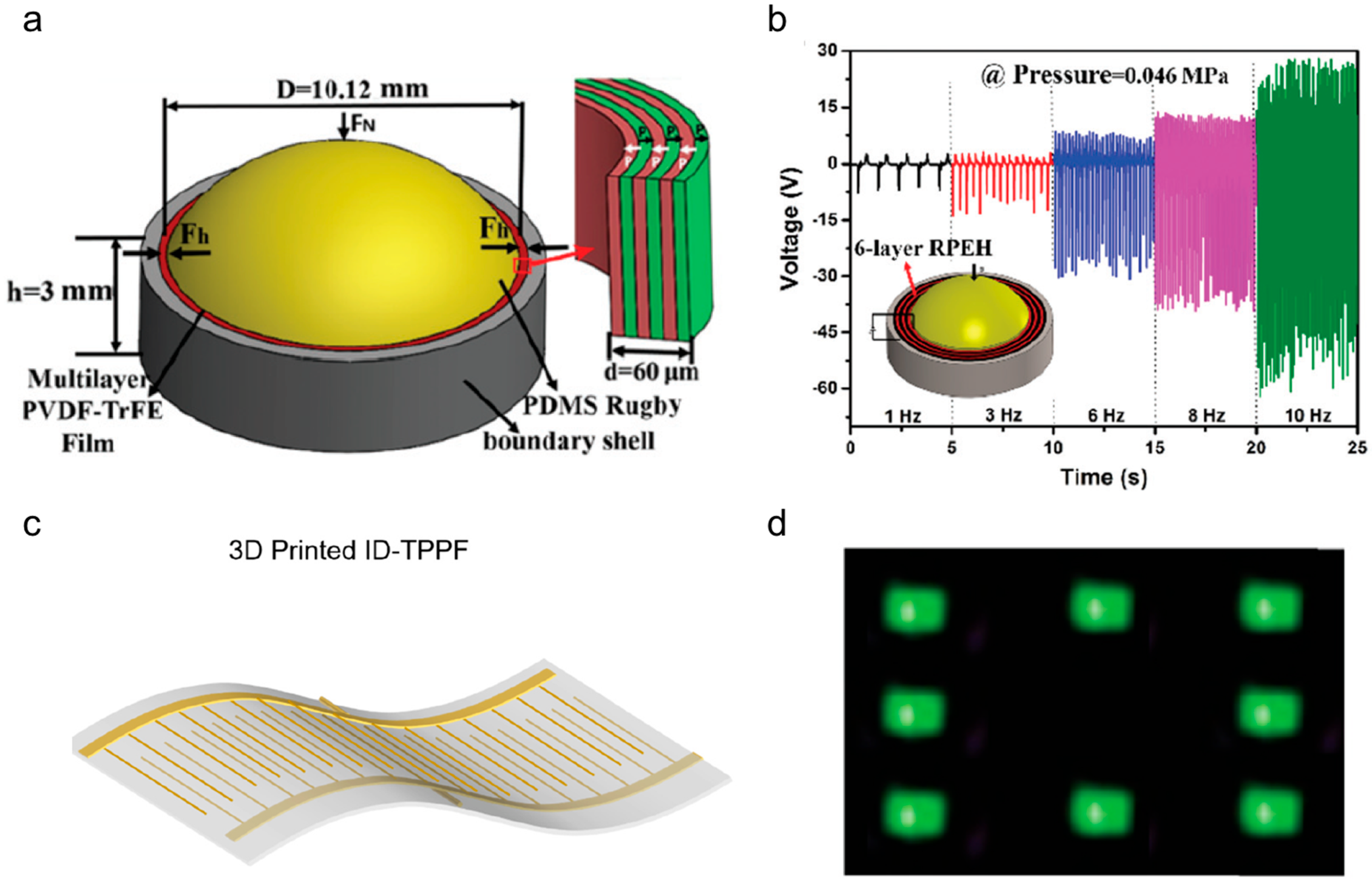
  74. Yuan, X.; Gao, X.; Yang, J.; Shen, X.; Li, Z.; You, S.; Wang, Z.; Dong, S. The large piezoelectricity and high power density of a 3D-printed multilayer copolymer in a rugby ball-structured mechanical energy harvester. Energy Environ. Sci. 2020, 13, 152–161. [Google Scholar] [CrossRef]
  75. Yuan, X.; Gao, X.; Shen, X.; Yang, J.; Li, Z.; Dong, S. A 3D-printed, alternatively tilt-polarized PVDF-TrFE polymer with enhanced piezoelectric effect for self-powered sensor application. Nano Energy 2021, 85, 105985. [Google Scholar] [CrossRef]
  76. Huan, Y.; Zhang, X.; Song, J.; Zhao, Y.; Wei, T.; Zhang, G.; Wang, X. High-performance piezoelectric composite nanogenerator based on Ag/(K, Na) NbO3 heterostructure. Nano Energy 2018, 50, 62–69. [Google Scholar] [CrossRef]
  77. Ponnamma, D.; Al-Maadeed, M.A.A. Influence of BaTiO3/white graphene filler synergy on the energy harvesting performance of a piezoelectric polymer nanocomposite. Sustain. Energy Fuels 2019, 3, 774–785. [Google Scholar] [CrossRef]
  78. Alam, M.M.; Mandal, D. Native cellulose microfiber-based hybrid piezoelectric generator for mechanical energy harvesting utility. ACS Appl. Mater. Interfaces 2016, 8, 1555–1558. [Google Scholar] [CrossRef]
  79. Zhang, Y.; Jeong, C.K.; Yang, T.; Sun, H.; Chen, L.-Q.; Zhang, S.; Chen, W.; Wang, Q. Bioinspired elastic piezoelectric composites for high-performance mechanical energy harvesting. J. Mater. Chem. A 2018, 6, 14546–14552. [Google Scholar] [CrossRef] [Green Version]
  80. Zhang, Z.; Liu, S.; Pan, Q.; Hong, Y.; Shan, Y.; Peng, Z.; Xu, X.; Liu, B.; Chai, Y.; Yang, Z. Van der Waals Exfoliation Processed Biopiezoelectric Submucosa Ultrathin Films. Adv. Mater. 2022, 34, 2200864. [Google Scholar] [CrossRef]
  81. Karan, S.K.; Maiti, S.; Kwon, O.; Paria, S.; Maitra, A.; Si, S.K.; Kim, Y.; Kim, J.K.; Khatua, B.B. Nature driven spider silk as high energy conversion efficient bio-piezoelectric nanogenerator. Nano Energy 2018, 49, 655–666. [Google Scholar] [CrossRef]
  82. Ghosh, S.K.; Mandal, D. Efficient natural piezoelectric nanogenerator: Electricity generation from fish swim bladder. Nano Energy 2016, 28, 356–365. [Google Scholar] [CrossRef]
  83. Wegert, Z.J.; Roberts, A.P.; Challis, V.J. Multi-objective structural optimisation of piezoelectric materials. Int. J. Solids Struct. 2022, 248, 111666. [Google Scholar] [CrossRef]
  84. Wang, B.; Zhong, J.; Zhong, Q.; Wu, N.; Cheng, X.; Li, W.; Liu, K.; Huang, L.; Hu, B.; Zhou, J. Sandwiched composite fluorocarbon film for flexible electret generator. Adv. Electron. Mater. 2016, 2, 1500408. [Google Scholar] [CrossRef]
  85. Pondrom, P.; Hillenbrand, J.; Sessler, G.; Bös, J.; Melz, T. Vibration-based energy harvesting with stacked piezoelectrets. Appl. Phys. Lett. 2014, 104, 172901. [Google Scholar] [CrossRef]
  86. Zhang, X.; Pondrom, P.; Sessler, G.M.; Ma, X. Ferroelectret nanogenerator with large transverse piezoelectric activity. Nano Energy 2018, 50, 52–61. [Google Scholar] [CrossRef]
  87. Hu, Y.; Wang, Z.L. Recent progress in piezoelectric nanogenerators as a sustainable power source in self-powered systems and active sensors. Nano Energy 2015, 14, 3–14. [Google Scholar] [CrossRef] [Green Version]
  88. Kim, D.; Cossé, J.; Cerdeira, C.H.; Gharib, M. Flapping dynamics of an inverted flag. J. Fluid Mech. 2013, 736, R1. [Google Scholar] [CrossRef] [Green Version]
  89. Orrego, S.; Shoele, K.; Ruas, A.; Doran, K.; Caggiano, B.; Mittal, R.; Kang, S.H. Harvesting ambient wind energy with an inverted piezoelectric flag. Appl. Energy 2017, 194, 212–222. [Google Scholar] [CrossRef]
  90. Zhang, J.; Fang, Z.; Shu, C.; Zhang, J.; Zhang, Q.; Li, C. A rotational piezoelectric energy harvester for efficient wind energy harvesting. Sens. Actuators A Phys. 2017, 262, 123–129. [Google Scholar] [CrossRef]
  91. Gao, T.; Liao, J.; Wang, J.; Qiu, Y.; Yang, Q.; Zhang, M.; Zhao, Y.; Qin, L.; Xue, H.; Xiong, Z. Highly oriented BaTiO3 film self-assembled using an interfacial strategy and its application as a flexible piezoelectric generator for wind energy harvesting. J. Mater. Chem. A 2015, 3, 9965–9971. [Google Scholar] [CrossRef] [Green Version]
  92. Priya, S.; Chen, C.-T.; Fye, D.; Zahnd, J. Piezoelectric windmill: A novel solution to remote sensing. Jpn. J. Appl. Phys. 2004, 44, 104. [Google Scholar] [CrossRef] [Green Version]
  93. Myers, R.; Vickers, M.; Kim, H.; Priya, S. Small scale windmill. Appl. Phys. Lett. 2007, 90, 054106. [Google Scholar] [CrossRef]
  94. Tien, C.M.T.; Goo, N.S. Use of a piezo-composite generating element for harvesting wind energy in an urban region. Aircr. Eng. Aerosp. Technol. 2010, 82, 376–381. [Google Scholar] [CrossRef]
  95. Karami, M.A.; Farmer, J.R.; Inman, D.J. Parametrically excited nonlinear piezoelectric compact wind turbine. Renew. Energy 2013, 50, 977–987. [Google Scholar] [CrossRef]
  96. Rezaei-Hosseinabadi, N.; Tabesh, A.; Dehghani, R.; Aghili, A. An efficient piezoelectric windmill topology for energy harvesting from low-speed air flows. IEEE Trans. Ind. Electron. 2014, 62, 3576–3583. [Google Scholar]
  97. Li, Z.; Peng, Y.; Xu, Z.; Peng, J.; Xin, L.; Wang, M.; Luo, J.; Xie, S.; Pu, H. Harnessing energy from suspension systems of oceanic vehicles with high-performance piezoelectric generators. Energy 2021, 228, 120523. [Google Scholar] [CrossRef]
  98. Nabavi, S.F.; Farshidianfar, A.; Afsharfard, A.; Khodaparast, H.H. An ocean wave-based piezoelectric energy harvesting system using breaking wave force. Int. J. Mech. Sci. 2019, 151, 498–507. [Google Scholar] [CrossRef] [Green Version]
  99. Taylor, G.W.; Burns, J.R.; Kammann, S.; Powers, W.B.; Welsh, T.R. The energy harvesting eel: A small subsurface ocean/river power generator. IEEE J. Ocean. Eng. 2001, 26, 539–547. [Google Scholar] [CrossRef] [Green Version]
  100. Mutsuda, H.; Tanaka, Y.; Patel, R.; Doi, Y.; Moriyama, Y.; Umino, Y. A painting type of flexible piezoelectric device for ocean energy harvesting. Appl. Ocean. Res. 2017, 68, 182–193. [Google Scholar] [CrossRef]
  101. Hwang, W.S.; Ahn, J.H.; Jeong, S.Y.; Jung, H.J.; Hong, S.K.; Choi, J.Y.; Cho, J.Y.; Kim, J.H.; Sung, T.H. Design of piezoelectric ocean-wave energy harvester using sway movement. Sens. Actuators A Phys. 2017, 260, 191–197. [Google Scholar] [CrossRef]
  102. Xu, X.; Wang, Y.; Li, P.; Xu, W.; Wei, L.; Wang, Z.; Yang, Z. A leaf-mimic rain energy harvester by liquid-solid contact electrification and piezoelectricity. Nano Energy 2021, 90, 106573. [Google Scholar] [CrossRef]
  103. Hendrowati, W.; Guntur, H.L.; Sutantra, I.N. Design, modeling and analysis of implementing a multilayer piezoelectric vibration energy harvesting mechanism in the vehicle suspension. Engineering 2012, 4, 24525. [Google Scholar] [CrossRef] [Green Version]
  104. Singh, K.B.; Bedekar, V.; Taheri, S.; Priya, S. Piezoelectric vibration energy harvesting system with an adaptive frequency tuning mechanism for intelligent tires. Mechatronics 2012, 22, 970–988. [Google Scholar] [CrossRef]
  105. Hong, S.D.; Kim, K.-B.; Hwang, W.; Song, Y.S.; Cho, J.Y.; Jeong, S.Y.; Ahn, J.H.; Kim, G.-H.; Cheong, H.; Sung, T.H. Enhanced energy-generation performance of a landfilled road-capable piezoelectric harvester to scavenge energy from passing vehicles. Energy Convers. Manag. 2020, 215, 112900. [Google Scholar] [CrossRef]
  106. Wang, Y.; Yang, Z.; Cao, D. On the offset distance of rotational piezoelectric energy harvesters. Energy 2021, 220, 119676. [Google Scholar] [CrossRef]
  107. Wang, Y.; Yang, Z.; Li, P.; Cao, D.; Huang, W.; Inman, D.J. Energy harvesting for jet engine monitoring. Nano Energy 2020, 75, 104853. [Google Scholar] [CrossRef]
  108. Wang, Y.; Zhao, Y.; Chen, C.; Cao, D.; Yang, Z. Misalignment-induced bending-torsional coupling vibrations of doubly-clamped nonlinear piezoelectric energy harvesters. Mech. Syst. Signal Process. 2022, 169, 108776. [Google Scholar] [CrossRef]
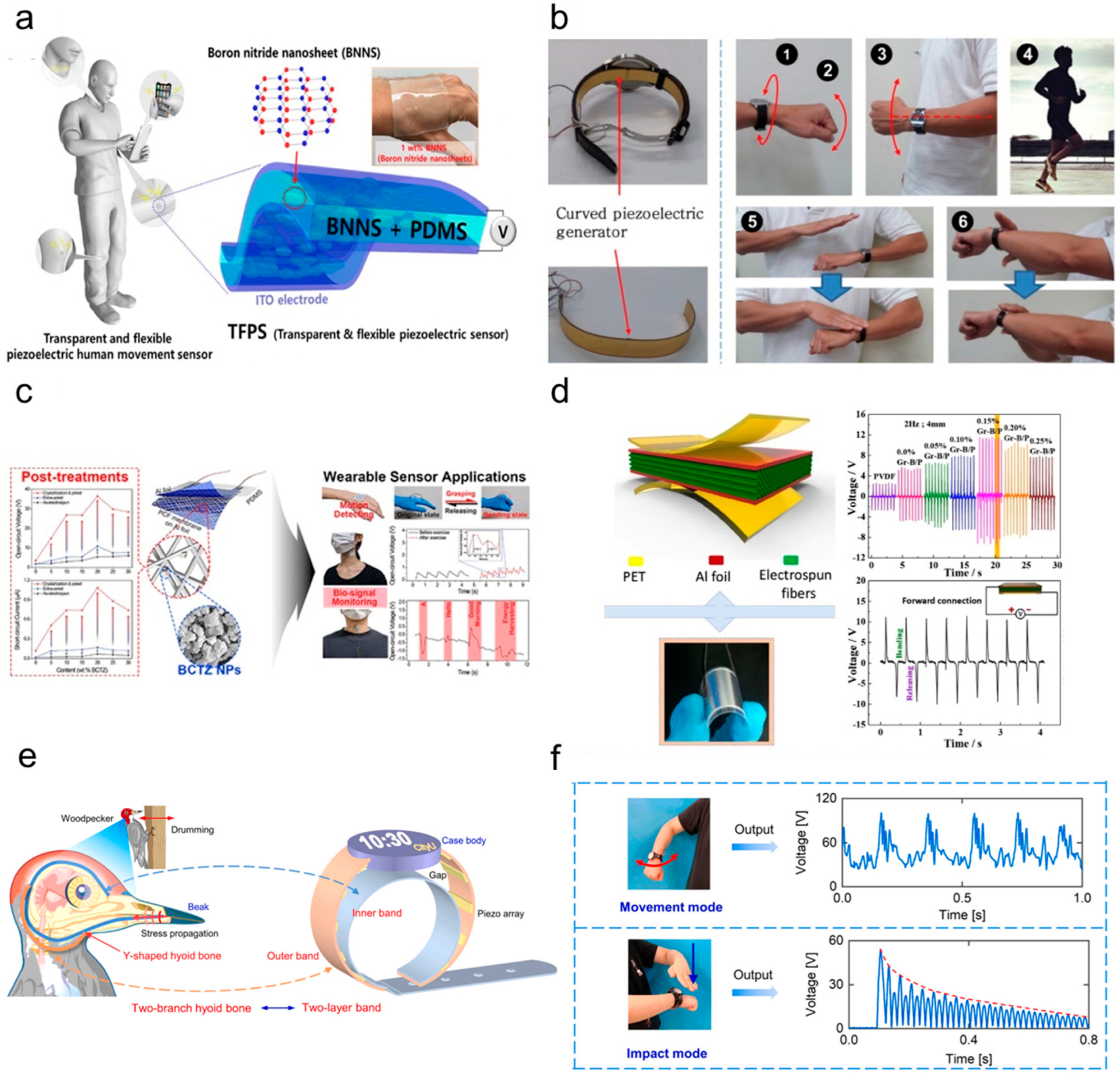
  109. Kim, K.-B.; Jang, W.; Cho, J.Y.; Woo, S.B.; Jeon, D.H.; Ahn, J.H.; Hong, S.D.; Koo, H.Y.; Sung, T.H. Transparent and flexible piezoelectric sensor for detecting human movement with a boron nitride nanosheet (BNNS). Nano Energy 2018, 54, 91–98. [Google Scholar] [CrossRef]
  110. Jung, W.-S.; Lee, M.-J.; Kang, M.-G.; Moon, H.G.; Yoon, S.-J.; Baek, S.-H.; Kang, C.-Y. Powerful curved piezoelectric generator for wearable applications. Nano Energy 2015, 13, 174–181. [Google Scholar] [CrossRef]
  111. Park, S.C.; Nam, C.; Baek, C.; Lee, M.-K.; Lee, G.-J.; Park, K.-I. Enhanced Piezoelectric Performance of Composite Fibers Based on Lead-Free BCTZ Ceramics and P (VDF-TrFE) Piezopolymer for Self-Powered Wearable Sensors. ACS Sustain. Chem. Eng. 2022, 10, 14370–14380. [Google Scholar] [CrossRef]
  112. Shi, K.; Sun, B.; Huang, X.; Jiang, P. Synergistic effect of graphene nanosheet and BaTiO3 nanoparticles on performance enhancement of electrospun PVDF nanofiber mat for flexible piezoelectric nanogenerators. Nano Energy 2018, 52, 153–162. [Google Scholar] [CrossRef]
  113. Wang, B.; Long, Z.; Hong, Y.; Pan, Q.; Lin, W.; Yang, Z. Woodpecker-mimic two-layer band energy harvester with a piezoelectric array for powering wrist-worn wearables. Nano Energy 2021, 89, 106385. [Google Scholar] [CrossRef]
  114. Wang, B.; Hong, Y.; Long, Z.; Pan, Q.; Li, P.; Xi, Y.; Yang, Z. Characterization of Wrist Motions and Bionic Energy Harvesting for Wrist Wearables. IEEE Internet Things J. 2022, 9, 21147–21156. [Google Scholar] [CrossRef]
  115. Hwang, G.T.; Byun, M.; Jeong, C.K.; Lee, K.J. Flexible piezoelectric thin-film energy harvesters and nanosensors for biomedical applications. Adv. Healthc. Mater. 2015, 4, 646–658. [Google Scholar] [CrossRef]
  116. Jiang, L.; Yang, Y.; Chen, R.; Lu, G.; Li, R.; Li, D.; Humayun, M.S.; Shung, K.K.; Zhu, J.; Chen, Y. Flexible piezoelectric ultrasonic energy harvester array for bio-implantable wireless generator. Nano Energy 2019, 56, 216–224. [Google Scholar] [CrossRef]
  117. Ansari, M.; Karami, M.A. Piezoelectric energy harvesting from heartbeat vibrations for leadless pacemakers. J. Phys. Conf. Ser. 2015, 660, 012121. [Google Scholar] [CrossRef] [Green Version]
  118. Deterre, M.; Lefeuvre, E.; Zhu, Y.; Woytasik, M.; Boutaud, B.; Dal Molin, R.D. Micro blood pressure energy harvester for intracardiac pacemaker. J. Microelectromech. Syst. 2013, 23, 651–660. [Google Scholar] [CrossRef]
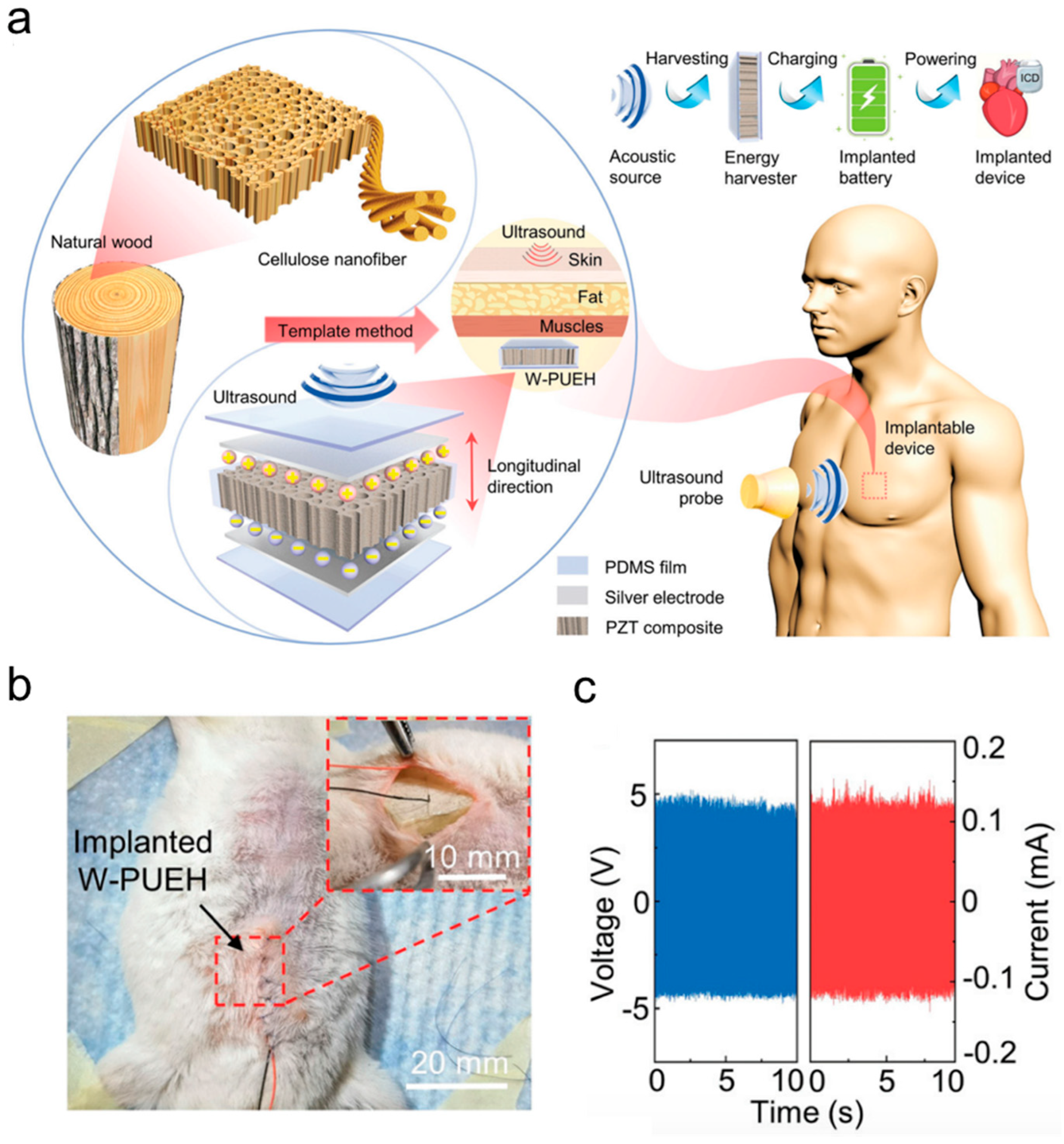
  119. Hong, Y.; Jin, L.; Wang, B.; Liao, J.; He, B.; Yang, T.; Long, Z.; Li, P.; Zhang, Z.; Liu, S. A wood-templated unidirectional piezoceramic composite for transmuscular ultrasonic wireless power transfer. Energy Environ. Sci. 2021, 14, 6574–6585. [Google Scholar] [CrossRef]
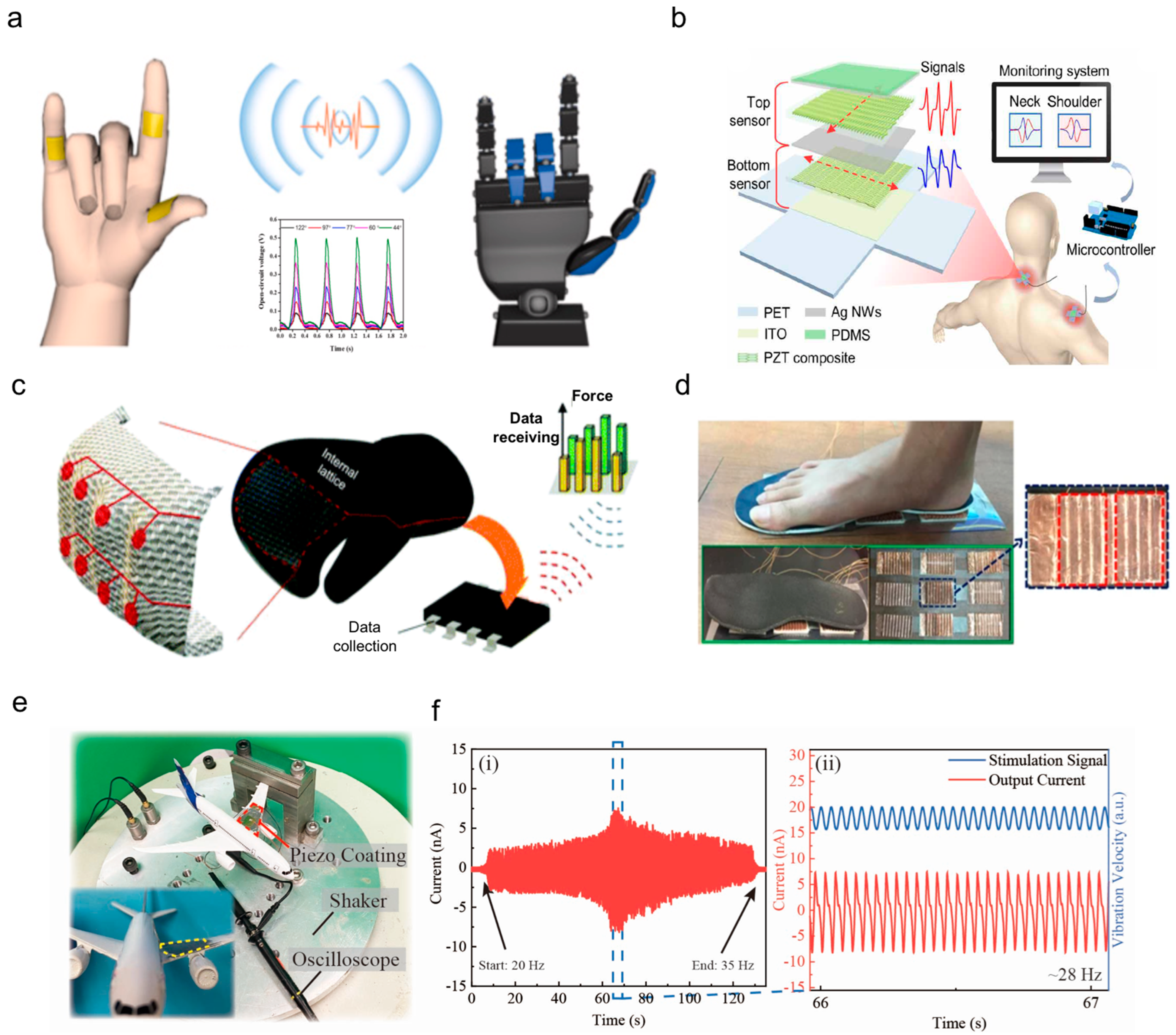
  120. Deng, W.; Yang, T.; Jin, L.; Yan, C.; Huang, H.; Chu, X.; Wang, Z.; Xiong, D.; Tian, G.; Gao, Y. Cowpea-structured PVDF/ZnO nanofibers based flexible self-powered piezoelectric bending motion sensor towards remote control of gestures. Nano Energy 2019, 55, 516–525. [Google Scholar] [CrossRef]
  121. Hong, Y.; Wang, B.; Lin, W.; Jin, L.; Liu, S.; Luo, X.; Pan, J.; Wang, W.; Yang, Z. Highly anisotropic and flexible piezoceramic kirigami for preventing joint disorders. Sci. Adv. 2021, 7, eabf0795. [Google Scholar] [CrossRef]
  122. Yao, D.; Cui, H.; Hensleigh, R.; Smith, P.; Alford, S.; Bernero, D.; Bush, S.; Mann, K.; Wu, H.F.; Chin-Nieh, M. Achieving the upper bound of piezoelectric response in tunable, wearable 3D printed nanocomposites. Adv. Funct. Mater. 2019, 29, 1903866. [Google Scholar] [CrossRef]
  123. Fuh, Y.K.; Wang, B.S.; Tsai, C.-Y. Self-powered pressure sensor with fully encapsulated 3D printed wavy substrate and highly-aligned piezoelectric fibers array. Sci. Rep. 2017, 7, 6759. [Google Scholar] [CrossRef] [PubMed] [Green Version]
  124. Liu, S.; Shan, Y.; Hong, Y.; Jin, Y.; Lin, W.; Zhang, Z.; Xu, X.; Wang, Z.; Yang, Z. 3D Conformal Fabrication of Piezoceramic Films. Adv. Sci. 2022, 9, 2106030. [Google Scholar] [CrossRef] [PubMed]
  125. Costa, P.; Pereira, J.N.; Pereira, N.; Castro, N.; Gonçalves, S.; Mendez, S.L. Recent progress on piezoelectric, pyroelectric, and magnetoelectric polymer-based energy-harvesting devices. Energy Technol. 2019, 7, 1800852. [Google Scholar] [CrossRef]
Figure 1. Three principle axes 1, 2, and 3, co-ordinate axes direction system in piezoelectric materials.
Nanoenergyadv 03 00005 g001
Figure 2. (a) The composite of textile-based hybrid nanogenerators, (b,c) SEM images of ZnO nanowires, (d) the image of the rolling sample. Adapted with permission. Copyright, [38] The Royal Society of Chemistry.
Nanoenergyadv 03 00005 g002
Figure 3. Recent progress on the PZT material. (a) The curved PZT bulks are fabricated via the function of gravity. Copyright 2021, [43] Springer Nature. (b) The flexible PZT thin films prepared on mica substrates. Copyright 2020, [44] American Chemistry Society. (c) The piezoelectric optimization method for PZT thin films. Copyright 2021, [45] Elsevier Ltd.
Nanoenergyadv 03 00005 g003
Figure 4. Schematic representation of the chain conformation for the α, β, and γ phases of PVDF. Reproduced with permission. Copyright 2014, [70] Elsevier Ltd.
Nanoenergyadv 03 00005 g004
Figure 5. (a) Schematic diagram of the piezoelectric energy harvester. (b) The open-circuit voltage measured when applying a uniform compressive stress. Copyright 2020, [74] Elsevier Ltd. (c) Schematic diagram of a flexible PVDF-TrFE piezoelectric film. (d) 8 LEDs were lit directly with the ID-TPPF when a finger tapping. The Royal Society of Chemistry. Copyright 2020, [75] The Royal Society of Chemistry.
Nanoenergyadv 03 00005 g005
Figure 6. (a) Photograph of the flexible Ag/(Na0.5K0.5)NbO3-PDMS piezoelectric nanogenerators device. (b) The relationship between the load resistance, output voltage, and output current of a 3% Ag piezoelectric nanogenerator under a compressive stress of 0.1 MPa and a frequency of 1 Hz. (c) Open-circuit voltage and short-circuit current of the p-NG devices. Copyright 2018, [76] Elsevier Ltd. (d) The stimulation method. (e) Circuit schematic of LEDs demonstrating the energy generation. (f) The output open-circuit voltage generated from the polarized sample. (g) The device lights up 20 LEDs. Copyright 2020, [17] Elsevier Ltd.
Nanoenergyadv 03 00005 g006
Figure 8. (a) Schematic diagram of the rotational piezoelectric energy harvester. The application of piezoelectric generator for wind energy harvesting. Copyright 2017, [89] Elsevier Ltd. (b) The piezoelectric generator was stirred by the paddle attached to the blade of a windmill which was driven by wind, (c) a photo of wind energy harvesting by the piezoelectric generator, (d,e) the open-circuit voltage and short-circuit current outputs generated from the piezoelectric generator, respectively. Copyright 2018, [90] Royal Society of Chemistry.
Nanoenergyadv 03 00005 g008
Figure 9. (a) Laminated structure of a pained FPED. (b) Comparison of electric power generated from each FPED at nearshore and offshore sites. Copyright 2017, [100] Elsevier Ltd. (c) Schematic of piezoelectric energy harvester and its operation. (d) Experimental setup used to evaluate the piezoelectric ocean wave energy harvester in sway condition. Copyright 2017, [101] Elsevier Ltd. (e) Natural raindrops falling on the leaves produce contact and vibration. (f) The structure of the leaf-mimic raindrop energy harvester. (g) The raindrop energy harvester is used to power the (h) temperature sensor. Copyright 2021, [102] Elsevier Ltd.
Nanoenergyadv 03 00005 g009aNanoenergyadv 03 00005 g009b
Figure 10. (a) The structure of the high-efficiency compressive-mode piezoelectric energy harvester and the working principle in the jet engine. The generated energy will be used to power the wireless sensor to monitor the real-time situation of the aircraft. (b) The output voltage and power during the rotation. (c) The resistance matching result of the energy harvester. The optimal resistance is around 40 kΩ. Copyright 2020, [107] Elsevier Ltd.
Nanoenergyadv 03 00005 g010
Figure 11. (a) The diagram shows a flexible and transparent piezoelectric sensor for human movement that includes two-layer ITO electrodes, a BNNS/PDMS piezoelectric active layer, and a proposed TFPS device (1 wt% BNNS/PDMS composite) that is worn on the hand. Copyright 2018, [109] Elsevier Ltd. (b) Piezoelectric generator application for the shoe insole and photos of the curved piezoelectric generator inserted in the insole. Copyright 2015, [110] Elsevier Ltd. (c) Schematic diagram of the fabrication of ultra-flexible piezoelectric energy harvesters based on a piezoelectric composite fiber membrane, including a photograph of the ultra-flexible piezoelectric energy harvesters attached to the skin of the back of the hand. Copyright 2022, [111] American Chemical Society. (d) Schematic structure of PENG- and time-dependent open-circuit voltages of PVDF and graphene-BT/PVDF(Gr-B/P) PENGs. Copyright 2018, [112] Elsevier Ltd. (e) The structure of the two-layer band energy harvester. (f) The output of the movement mode and impact mode of the energy harvester. Copyright 2021, [113] Elsevier Ltd.
Nanoenergyadv 03 00005 g011
Figure 12. (a) The structure and working principle of the wood-templated piezoelectric ultrasonic energy harvester. (b) The device was planted into the mice. (c) The in vivo piezoelectric output under ultrasonic stimulation. Copyright 2021, [119] Royal Society of Chemistry.
Nanoenergyadv 03 00005 g012
Figure 13. (a) Schematic diagram of self-powered piezoelectric sensor based on cowpea-structured PVDF/ZnO nanofibers towards the remote control of gestures. Copyright 2019, [120] Elsevier Ltd. (b) Schematic illustration of the system to monitor musculoskeletal disorders. The signals produced from the attached sensors are transmitted to an intelligent terminal through a microcontroller for further analysis. Copyright 2021, [121] AAAS. (c) Schematic of the wireless self-sensing boxing glove. Copyright 2019, [122] Wiley-VCH. (d) Photograph of integrated self-powered foot pressure sensor arrays and two-dimensional contour plot mapping of pressure potential from the objects. Copyright 2019, [123] Springer Nature. (e) The piezoelectric thin film is grown on the wing of the plane model to serve as a self-powered structural health monitor. (f) The vibration response of the sensor under the frequency sweep ranges from 20 to 35 Hz. (i) The vibration signal ranges from 20–35 Hz. (ii) The zoomed in signal around 28 Hz. Copyright 2022, [124] Willey.
Nanoenergyadv 03 00005 g013
Table 1. The output performances of piezoelectric nanogenerators based on lead-free piezoelectric materials.
MaterialsFiller’s ShapePressure (kPa)Mechanical Stability Cyclic TimesOutput Voltage (V)Power (μw)Power Density (μw/cm2)References
BZT/PVDFparticles17.6500~1210.16[49]
BT-graphitic carbons/PDMSparticlesBending1200~3--[50]
BT/PVDFparticles10 MPa2000~150--[51]
BT/PDMSnanofibers21000~2.670.1841-[52]
NKLN/PDMSNano cubes20 N-~48--[53]
BCTZ-Ag/PDMSparticlesBending10,000~1580.89[54]
BT/PDMSnanocubes9.881600~9014.20.7[55]
BT/Bacterial celluloseparticles-3000~123.90.65[56]
BaTiO3/P(VDF-TrFE)particles50012,000~13.2-12.7[57]
PZT/PVDFparticles8.5-~55-36[58]
PZT/glass fiberparticlesBending36,000~601.63-[59]
BaTi2O5/PVDF-5%nanorodsCantilever330,000~406.60.82[60]
PZT/PETThin film -~0.695.6-[61]
BT/PDMSparticles10 N3200~3135.645.4[62]
BCZTThin filmPressing20,0002.3-450[63]
Table 2. The main advantages, drawbacks, and potential applications of the micro-power generators.
TypesAdvantageDrawbackPotential Application
Zinc oxideSimple structureLow output voltagesPiezoelectric nano-generators
Piezoelectric ceramicsEasy to fabricateHigh dielectric loss, brittlePiezoelectric actuators
Piezoelectric single crystalsHigher piezoelectric constantHigh-temperature sensitivityPiezoelectric transducers
Organic polymer materialsHigh mechanical strength and thermal stabilityLower piezoelectric coefficients (d33 ≤ 30 pC/N)Sensor or energy harvester
Composite materialsHigh coupling factors, low acoustic impedanceHard to fabricateSensor or energy harvester
Bio-inspired piezoelectric materialsBiodegradable and biocompatible natureHigher costsSensor or energy harvester
Piezoelectret foamsLow cost, lead-free, environmentallyLimited thermal stabilitySensor or energy harvester
Table 3. Summary of various windmill-style piezoelectric energy harvesters.
DeviceTransducer TypeGenerator MaterialDimensionsWind Speed
(m s−1)
Output PowerReferences
Fan-type windmillPiezoelectric bimorphPZT-5H60 × 20 × 0.6 mm34.477.5 mW[92]
Vane-type vertical windmillPiezoelectric bimorphPZT-5H96 × 107 × 66 mm34.475 mW[93]
Fan-type windmillPiezo-composite beamPZT-5H72 × 12 × 0.5 mm3less than 5 m s−18.5 mW[94]
Contact-less windmillPiezomagnetic generatorPZT-5A80 × 80 × 175 mm34.474 mW[95]
Fan-type windmillPiezomagnetic generatorPZT-5A31 mm diameter0.9363 μW[96]
Disclaimer/Publisher’s Note: The statements, opinions and data contained in all publications are solely those of the individual author(s) and contributor(s) and not of MDPI and/or the editor(s). MDPI and/or the editor(s) disclaim responsibility for any injury to people or property resulting from any ideas, methods, instructions or products referred to in the content.

