
Manufacturing of Carbon Nanotube-Polystyrene Filament for 3D Printing: Nanoparticle Dispersion and Electromagnetic Properties

 , and
, and 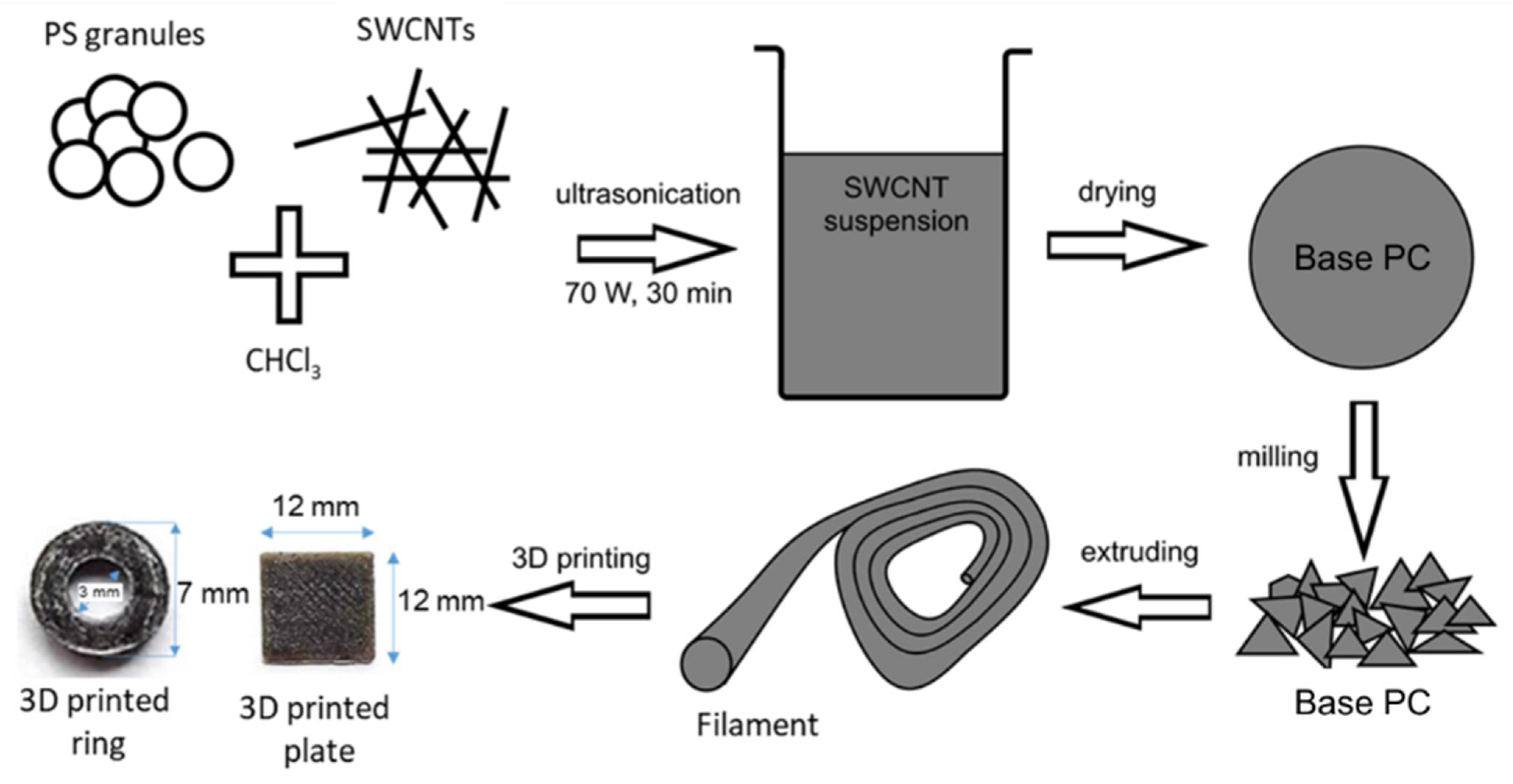
Abstract
:1. Introduction
2. Materials and Methods
2.1. Materials
2.2. Filaments Preparation
2.3. 3D Printing
2.4. Microscopic Characterization
2.5. Electromagnetic Measurements
3. Results and Discussion
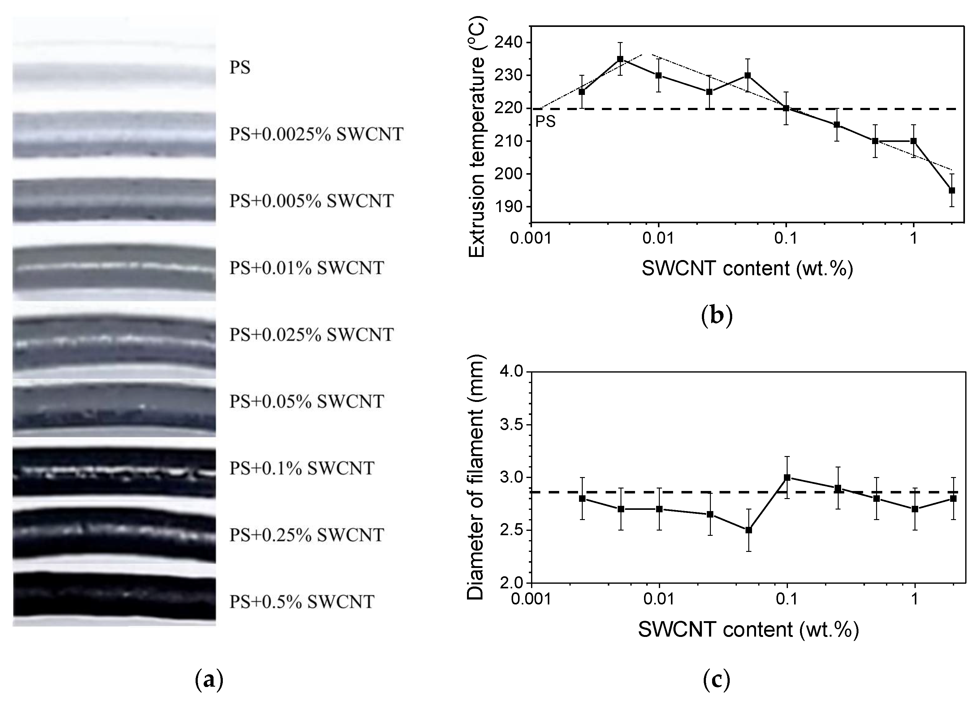
3.1. Optimization of Extrusion Conditions
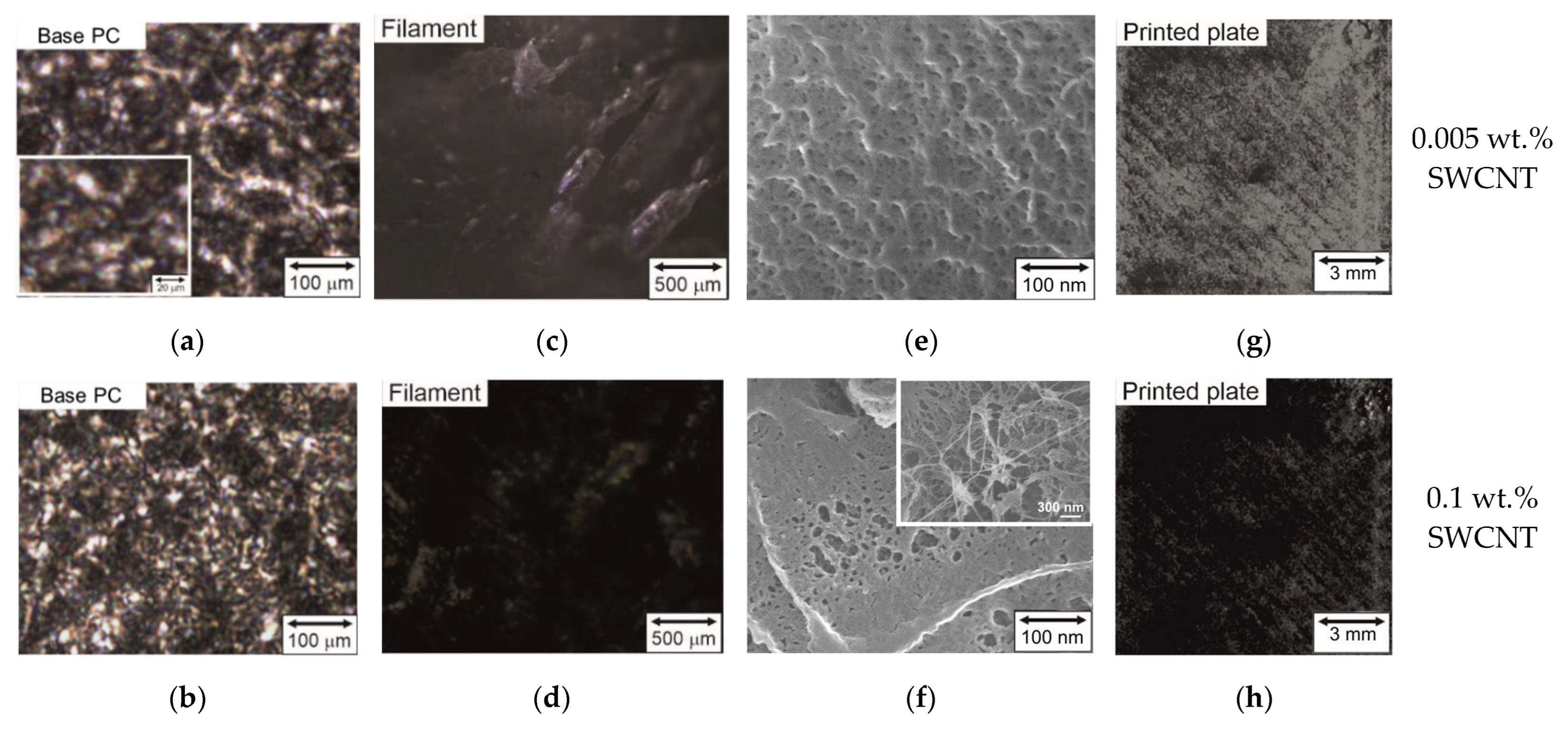
3.2. Morphology of Base PCs and Filaments
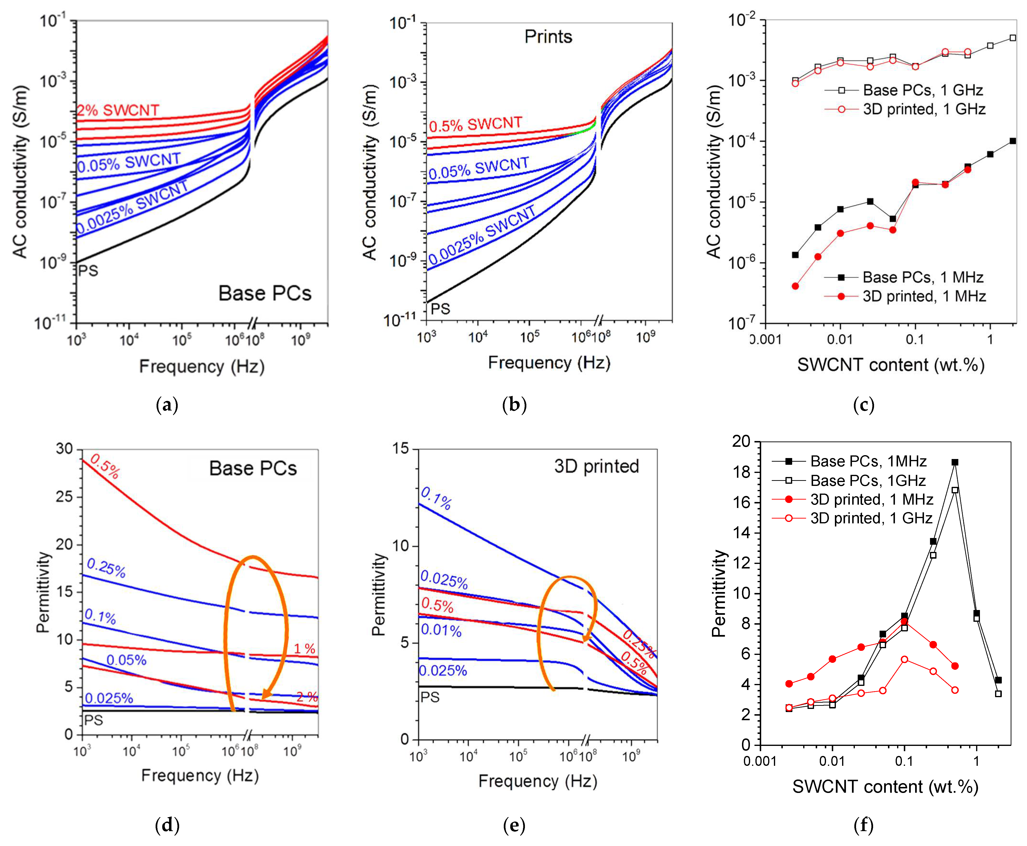
3.3. Electrical Properties of Base PCs and Printed Samples
4. Conclusions
Supplementary Materials
Author Contributions
Funding
Acknowledgments
Conflicts of Interest
References
- Zhang, L.; Du, W.; Nautiyal, A.; Liu, Z.; Zhang, X. Recent Progress on Nanostructured Conducting Polymers and Composites: Synthesis, Application and Future Aspects. Sci. China Mater. 2018, 61, 303–352. [Google Scholar] [CrossRef] [Green Version]
- Stansbury, J.W.; Idacavage, M.J. 3D Printing with Polymers: Challenges among Expanding Options and Opportunities. Dent. Mater. 2016, 32, 54–64. [Google Scholar] [CrossRef] [PubMed]
- Saleh Alghamdi, S.; John, S.; Roy Choudhury, N.; Dutta, N.K. Additive Manufacturing of Polymer Materials: Progress, Promise and Challenges. Polymers 2021, 13, 753. [Google Scholar] [CrossRef]
- Wu, Y.; Isakov, D.; Grant, P. Fabrication of Composite Filaments with High Dielectric Permittivity for Fused Deposition 3D Printing. Materials 2017, 10, 1218. [Google Scholar] [CrossRef] [Green Version]
- Jonušauskas, L.; Juodkazis, S.; Malinauskas, M. Optical 3D Printing: Bridging the Gaps in the Mesoscale. J. Opt. 2018, 20, 053001. [Google Scholar] [CrossRef]
- Wang, H.; Wang, H.; Zhang, W.; Yang, J.K.W. Toward Near-Perfect Diffractive Optical Elements via Nanoscale 3D Printing. ACS Nano 2020, 14, 10452–10461. [Google Scholar] [CrossRef] [PubMed]
- Kestilä, A.; Nordling, K.; Miikkulainen, V.; Kaipio, M.; Tikka, T.; Salmi, M.; Auer, A.; Leskelä, M.; Ritala, M. Towards Space-Grade 3D-Printed, ALD-Coated Small Satellite Propulsion Components for Fluidics. Addit. Manuf. 2018, 22, 31–37. [Google Scholar] [CrossRef]
- Zaccardi, F.; Toto, E.; Santonicola, M.G.; Laurenzi, S. 3D Printing of Radiation Shielding Polyethylene Composites Filled with Martian Regolith Simulant Using Fused Filament Fabrication. Acta Astronaut. 2022, 190, 1–13. [Google Scholar] [CrossRef]
- Sydney Gladman, A.; Garcia-Leiner, M.; Sauer-Budge, A.F. Emerging Polymeric Materials in Additive Manufacturing for Use in Biomedical Applications. AIMS Bioeng. 2019, 6, 1–20. [Google Scholar] [CrossRef]
- Cresswell-Boyes, A.J.; Davis, G.R.; Krishnamoorthy, M.; Mills, D.; Barber, A.H. Composite 3D Printing of Biomimetic Human Teeth. Sci. Rep. 2022, 12, 7830. [Google Scholar] [CrossRef]
- Saroia, J.; Wang, Y.; Wei, Q.; Lei, M.; Li, X.; Guo, Y.; Zhang, K. A Review on 3D Printed Matrix Polymer Composites: Its Potential and Future Challenges. Int. J. Adv. Manuf. Technol. 2020, 106, 1695–1721. [Google Scholar] [CrossRef]
- Manoj Prabhakar, M.; Saravanan, A.K.; Haiter Lenin, A.; Jerin Leno, I.; Mayandi, K.; Sethu Ramalingam, P. A Short Review on 3D Printing Methods, Process Parameters and Materials. Mater. Today Proc. 2021, 45, 6108–6114. [Google Scholar] [CrossRef]
- Kim, H.J.; Lim, S.W.; Lee, M.K.; Ju, S.W.; Park, S.H.; Ahn, J.S.; Hwang, K.G. Which Three-Dimensional Printing Technology Can Replace Conventional Manual Method of Manufacturing Oral Appliance? A Preliminary Comparative Study of Physical and Mechanical Properties. Appl. Sci. 2022, 12, 130. [Google Scholar] [CrossRef]
- Yang, Y.; Chen, Z.; Song, X.; Zhu, B.; Hsiai, T.; Wu, P.-I.; Xiong, R.; Shi, J.; Chen, Y.; Zhou, Q.; et al. Three Dimensional Printing of High Dielectric Capacitor Using Projection Based Stereolithography Method. Nano Energy 2016, 22, 414–421. [Google Scholar] [CrossRef] [Green Version]
- Hardin, J.O.; Grabowski, C.A.; Lucas, M.; Durstock, M.F.; Berrigan, J.D. All-Printed Multilayer High Voltage Capacitors with Integrated Processing Feedback. Addit. Manuf. 2019, 27, 327–333. [Google Scholar] [CrossRef]
- Chizari, K.; Arjmand, M.; Liu, Z.; Sundararaj, U.; Therriault, D. Three-Dimensional Printing of Highly Conductive Polymer Nanocomposites for EMI Shielding Applications. Mater. Today Commun. 2017, 11, 112–118. [Google Scholar] [CrossRef]
- Prashantha, K.; Roger, F. Multifunctional Properties of 3D Printed Poly(Lactic Acid)/Graphene Nanocomposites by Fused Deposition Modeling. J. Macromol. Sci. Part A 2017, 54, 24–29. [Google Scholar] [CrossRef]
- Paddubskaya, A.; Valynets, N.; Kuzhir, P.; Batrakov, K.; Maksimenko, S.; Kotsilkova, R.; Velichkova, H.; Petrova, I.; Biró, I.; Kertész, K.; et al. Electromagnetic and Thermal Properties of Three-Dimensional Printed Multilayered Nano-Carbon/Poly(Lactic) Acid Structures. J. Appl. Phys. 2016, 119, 135102. [Google Scholar] [CrossRef] [Green Version]
- Guo, S.Z.; Yang, X.; Heuzey, M.C.; Therriault, D. 3D Printing of a Multifunctional Nanocomposite Helical Liquid Sensor. Nanoscale 2015, 7, 6451–6456. [Google Scholar] [CrossRef]
- Hauck, B.C.; Ruprecht, B.R.; Riley, P.C. Accurate and on-Demand Chemical Sensors: A Print-in-Place Ion Mobility Spectrometer. Sens. Actuators B Chem. 2022, 362, 131791. [Google Scholar] [CrossRef]
- Vu, C.C.; Nguyen, T.T.; Kim, S.; Kim, J. Effects of 3D Printing-Line Directions for Stretchable Sensor Performances. Materials 2021, 14, 1791. [Google Scholar] [CrossRef] [PubMed]
- Wu, C.S.; Liao, H.T. Interface Design of Environmentally Friendly Carbon Nanotube-Filled Polyester Composites: Fabrication, Characterisation, Functionality and Application. Express Polym. Lett. 2017, 11, 187–198. [Google Scholar] [CrossRef]
- Berman, B. 3-D Printing: The New Industrial Revolution. Bus. Horiz. 2012, 55, 155–162. [Google Scholar] [CrossRef]
- Zuo, Y.; Su, X.; Li, X.; Yao, Z.; Yu, T.; Zhou, J.; Li, J.; Lu, J.; Ding, J. Multimaterial 3D-Printing of Graphene/ Li0.35Zn0.3Fe2.35O4 and Graphene/Carbonyl Iron Composites with Superior Microwave Absorption Properties and Adjustable Bandwidth. Carbon 2020, 167, 62–74. [Google Scholar] [CrossRef]
- Acquah, S.F.A.; Leonhardt, B.E.; Nowotarski, M.S.; Magi, J.M.; Chambliss, K.A.; Venzel, T.E.S.; Delekar, S.D.; Al-Hariri, L.A. Carbon Nanotubes and Graphene as Additives in 3D Printing. In Carbon Nanotubes-Current Progress of Their Polymer Composites; InTech: Vienna, Austria, 2016; pp. 227–251. [Google Scholar]
- Fiedor, P.; Ortyl, J. A New Approach to Micromachining: High-Precision and Innovative Additive Manufacturing Solutions Based on Photopolymerization Technology. Materials 2020, 13, 2951. [Google Scholar] [CrossRef]
- Joshi, A.; Goh, J.K.; Goh, K.E.J. Polymer-Based Conductive Composites for 3D and 4D Printing of Electrical Circuits. In 3D and 4D Printing of Polymer Nanocomposite Materials; Elsevier: Amsterdam, The Netherlands, 2020; pp. 45–83. ISBN 9780128168059. [Google Scholar]
- Sanatgar, R.H.; Cayla, A.; Campagne, C.; Nierstrasz, V. Morphological and Electrical Characterization of Conductive Polylactic Acid Based Nanocomposite before and after FDM 3D Printing. J. Appl. Polym. Sci. 2019, 136, 47040. [Google Scholar] [CrossRef]
- Shemelya, C.; De La Rosa, A.; Torrado, A.R.; Yu, K.; Domanowski, J.; Bonacuse, P.J.; Martin, R.E.; Juhasz, M.; Hurwitz, F.; Wicker, R.B.; et al. Anisotropy of Thermal Conductivity in 3D Printed Polymer Matrix Composites for Space Based Cube Satellites. Addit. Manuf. 2017, 16, 186–196. [Google Scholar] [CrossRef]
- Shah, S.; Shiblee, M.N.I.; Rahman, J.M.H.; Basher, S.; Mir, S.H.; Kawakami, M.; Furukawa, H.; Khosla, A. 3D Printing of Electrically Conductive Hybrid Organic–Inorganic Composite Materials. Microsyst. Technol. 2018, 24, 4341–4345. [Google Scholar] [CrossRef]
- Gnanasekaran, K.; Heijmans, T.; van Bennekom, S.; Woldhuis, H.; Wijnia, S.; de With, G.; Friedrich, H. 3D Printing of CNT- and Graphene-Based Conductive Polymer Nanocomposites by Fused Deposition Modeling. Appl. Mater. Today 2017, 9, 21–28. [Google Scholar] [CrossRef]
- Parvej, M.S.; Khan, M.I.; Hossain, M.K. Preparation of Nanoparticle-Based Polymer Composites. In Nanoparticle-Based Polymer Composites; Elsevier: Amsterdam, The Netherlands, 2022; pp. 55–94. [Google Scholar]
- Sankaran, S.; Deshmukh, K.; Ahamed, M.B.; Khadheer Pasha, S.K. Recent Advances in Electromagnetic Interference Shielding Properties of Metal and Carbon Filler Reinforced Flexible Polymer Composites: A Review. Compos. Part A Appl. Sci. Manuf. 2018, 114, 49–71. [Google Scholar] [CrossRef]
- Thomassin, J.M.; Jérôme, C.; Pardoen, T.; Bailly, C.; Huynen, I.; Detrembleur, C. Polymer/Carbon Based Composites as Electromagnetic Interference (EMI) Shielding Materials. Mater. Sci. Eng. R Rep. 2013, 74, 211–232. [Google Scholar] [CrossRef]
- Bychanok, D.S.; Shuba, M.V.; Kuzhir, P.P.; Maksimenko, S.A.; Kubarev, V.V.; Kanygin, M.A.; Sedelnikova, O.V.; Bulusheva, L.G.; Okotrub, A.V. Anisotropic Electromagnetic Properties of Polymer Composites Containing Oriented Multiwall Carbon Nanotubes in Respect to Terahertz Polarizer Applications. J. Appl. Phys. 2013, 114, 114304. [Google Scholar] [CrossRef] [Green Version]
- Okotrub, A.V.; Yudanov, N.F.; Aleksashin, V.M.; Bulusheva, L.G.; Komarova, O.A.; Kostas, U.O.; Gevko, P.N.; Antyufeeva, N.V.; Il’chenko, S.I.; Gunyaev, G.M. Study of Thermal and Mechanical Properties of Composites Based on Arc-Grown Carbon Nanotubes and Heat-Resistant Cyanoether Binder. Polym. Sci. Ser. A 2007, 49, 702–707. [Google Scholar] [CrossRef]
- Larionov, S.A.; Deev, I.S.; Petrova, G.N.; Bader, E.Y. Influence of Carbon Fillers on Electrophysical, Mechanical and Rheological Properties of Polyethylene. Proc. VIAM 2013, 9, 1–10. [Google Scholar]
- Klyuev, I.Y.; Shevchenko, V.G.; Kuperman, A.M.; Solodilov, V.I. Electrophysical Characteristics of Epoxy Nanocomposites with Ultralow Percolation Thresholds. Inorg. Mater. Appl. Res. 2020, 11, 416–419. [Google Scholar] [CrossRef]
- Yan, Y.; Cui, J.; Zhao, S.; Zhang, J.; Liu, J.; Cheng, J. Interface Molecular Engineering of Single-Walled Carbon Nanotube/Epoxy Composites. J. Mater. Chem. 2012, 22, 1928–1936. [Google Scholar] [CrossRef]
- Hoseini, A.H.A.; Arjmand, M.; Sundararaj, U.; Trifkovic, M. Significance of Interfacial Interaction and Agglomerates on Electrical Properties of Polymer-Carbon Nanotube Nanocomposites. Mater. Des. 2017, 125, 126–134. [Google Scholar] [CrossRef]
- Kausar, A.; Ahmad, S.; Salman, S.M. Effectiveness of Polystyrene/Carbon Nanotube Composite in Electromagnetic Interference Shielding Materials: A Review. Polym. Plast. Technol. Eng. 2017, 56, 1027–1042. [Google Scholar] [CrossRef]
- Ayewah, D.O.O.; Davis, D.C.; Krishnamoorti, R.; Lagoudas, D.C.; Sue, H.-J.; Willson, M. A Surfactant Dispersed SWCNT-Polystyrene Composite Characterized for Electrical and Mechanical Properties. Compos. Part A Appl. Sci. Manuf. 2010, 41, 842–849. [Google Scholar] [CrossRef]
- Sedelnikova, O.V.; Kanygin, M.A.; Korovin, E.Y.; Bulusheva, L.G.; Suslyaev, V.I.; Okotrub, A.V. Effect of Fabrication Method on the Structure and Electromagnetic Response of Carbon Nanotube/Polystyrene Composites in Low-Frequency and Ka Bands. Compos. Sci. Technol. 2014, 102, 59–64. [Google Scholar] [CrossRef]
- Spitalsky, Z.; Tasis, D.; Papagelis, K.; Galiotis, C. Carbon Nanotube-Polymer Composites: Chemistry, Processing, Mechanical and Electrical Properties. Prog. Polym. Sci. 2010, 35, 357–401. [Google Scholar] [CrossRef]
- Guo, B.; Ji, X.; Chen, X.; Li, G.; Lu, Y.; Bai, J. A Highly Stretchable and Intrinsically Self-Healing Strain Sensor Produced by 3D Printing. Virtual Phys. Prototyp. 2020, 15, 520–531. [Google Scholar] [CrossRef]
- Zhang, A.; Luan, J.; Zheng, Y.; Sun, L.; Tang, M. Effect of Percolation on the Electrical Conductivity of Amino Molecules Non-Covalently Coated Multi-Walled Carbon Nanotubes/Epoxy Composites. Appl. Surf. Sci. 2012, 258, 8492–8497. [Google Scholar] [CrossRef]
- Watt, M.R.; Gerhardt, R.A. Factors That Affect Network Formation in Carbon Nanotube Composites and Their Resultant Electrical Properties. J. Compos. Sci. 2020, 4, 100. [Google Scholar] [CrossRef]
- Grossiord, N.; Loos, J.; Van Laake, L.; Maugey, M.; Zakri, C.; Koning, C.E.; John Hart, A. High-Conductivity Polymer Nanocomposites Obtained by Tailoring the Characteristics of Carbon Nanotube Fillers. Adv. Funct. Mater. 2008, 18, 3226–3234. [Google Scholar] [CrossRef] [Green Version]
- Kanygin, M.A.; Sedelnikova, O.V.; Bulusheva, L.G.; Okotrub, A.V. Polymer-Assisted Forge-Rolling Disaggregation of Detonation Nanodiamonds and Onion-like Carbon. Int. J. Nanotechnol. 2015, 12, 182. [Google Scholar] [CrossRef]
- Mahfuz, H.; Khan, M.R.; Leventouri, T.; Liarokapis, E. Investigation of MWCNT Reinforcement on the Strain Hardening Behavior of Ultrahigh Molecular Weight Polyethylene. J. Nanotechnol. 2011, 2011, 1–9. [Google Scholar] [CrossRef] [Green Version]
- Kanygin, M.A.; Sedelnikova, O.V.; Asanov, I.P.; Bulusheva, L.G.; Okotrub, A.V.; Kuzhir, P.P.; Plyushch, A.O.; Maksimenko, S.A.; Lapko, K.N.; Sokol, A.A.; et al. Effect of Nitrogen Doping on the Electromagnetic Properties of Carbon Nanotube-Based Composites. J. Appl. Phys. 2013, 113, 144315. [Google Scholar] [CrossRef] [Green Version]
- Smygalina, P.P.; Trofimov, E.A.; Pidotova, D.A.; Badin, A.V. Evaluation of the Effect of Porosity of Composite ABS Filament with MWCNTs on Its Electrophysical Properties in the EHF Range. In Proceedings of the Sixteenth All-Russian Conference of Student Research Incubators, Tomsk, Russia, 13–15 May 2019; pp. 69–72. [Google Scholar]
- Gurova, O.A.; Arhipov, V.E.; Koroteev, V.O.; Guselnikova, T.Y.; Asanov, I.P.; Sedelnikova, O.V.; Okotrub, A.V. Purification of Single-Walled Carbon Nanotubes Using Acid Treatment and Magnetic Separation. Phys. Status Solidi B 2019, 256, 1800742. [Google Scholar] [CrossRef]
- Sedelnikova, O.V.; Baskakova, K.I.; Gusel’nikov, A.V.; Plyusnin, P.E.; Bulusheva, L.G.; Okotrub, A.V. Percolative Composites with Carbon Nanohorns: Low-Frequency and Ultra-High Frequency Response. Materials 2019, 12, 1848. [Google Scholar] [CrossRef] [Green Version]
- Dastjerdi, R.; Mojtahedi, M.R.M.; Shoshtari, A.M. Comparing the Effect of Three Processing Methods for Modification of Filament Yarns with Inorganic Nanocomposite Filler and Their Bioactivity against Staphylococcus Aureus. Macromol. Res. 2009, 17, 378–387. [Google Scholar] [CrossRef]
- Liu, Z.; Tu, R.; Liao, Q.; Hu, H.; Yang, J.; He, Y.; Bian, H.; Ma, L.; Liu, W. High Thermal Conductivity of Flake Graphite Reinforced Polyethylene Composites Fabricated by the Powder Mixing Method and the Melt-Extruding Process. Polymers 2018, 10, 693. [Google Scholar] [CrossRef] [Green Version]
- Spinelli, G.; Lamberti, P.; Tucci, V.; Kotsilkova, R.; Ivanov, E.; Menseidov, D.; Naddeo, C.; Romano, V.; Guadagno, L.; Adami, R.; et al. Nanocarbon/Poly(Lactic) Acid for 3D Printing: Effect of Fillers Content on Electromagnetic and Thermal Properties. Materials 2019, 12, 2369. [Google Scholar] [CrossRef] [Green Version]
- Dorigato, A.; Moretti, V.; Dul, S.; Unterberger, S.H.; Pegoretti, A. Electrically Conductive Nanocomposites for Fused Deposition Modelling. Synth. Met. 2017, 226, 7–14. [Google Scholar] [CrossRef]
- Oseli, A.; Vesel, A.; Mozetič, M.; Žagar, E.; Huskić, M.; Slemenik Perše, L. Nano-Mesh Superstructure in Single-Walled Carbon Nanotube/Polyethylene Nanocomposites, and Its Impact on Rheological, Thermal and Mechanical Properties. Compos. Part A Appl. Sci. Manuf. 2020, 136, 105972. [Google Scholar] [CrossRef]
- Mitchell, C.A.; Bahr, J.L.; Arepalli, S.; Tour, J.M.; Krishnamoorti, R. Dispersion of Functionalized Carbon Nanotubes in Polystyrene. Macromolecules 2002, 35, 8825–8830. [Google Scholar] [CrossRef]
- Gavrilov, N.N.; Okotrub, A.V.; Bulusheva, L.G.; Sedelnikova, O.V.; Yushina, I.V.; Kuznetsov, V.L. Dielectric Properties of Polystyrene/Onion-like Carbon Composites in Frequency Range of 0.5–500 kHz. Compos. Sci. Technol. 2010, 70, 719–724. [Google Scholar] [CrossRef]
- Nicolson, A.M.; Ross, G.F. Measurement of the Intrinsic Properties of Materials by Time-Domain Techniques. IEEE Trans. Instrum. Meas. 1970, 19, 377–382. [Google Scholar] [CrossRef] [Green Version]
- Weir, W.B. Automatic Measurement of Complex Dielectric Constant and Permeability. Proc. IEEE 1974, 62, 33–36. [Google Scholar] [CrossRef]
- EM-Calculator, Online Calculator of Complex Dielectric Permittivity and Magnetic Permeability in Microwaves. 2022. Available online: http://em-calculator.com (accessed on 1 September 2022).
- Kharchenko, S.B.; Douglas, J.F.; Obrzut, J.; Grulke, E.A.; Migler, K.B. Flow-Induced Properties of Nanotube-Filled Polymer Materials. Nat. Mater. 2004, 3, 564–568. [Google Scholar] [CrossRef]
- Grady, B.P.; Paul, A.; Peters, J.E.; Ford, W.T. Glass Transition Behavior of Single-Walled Carbon Nanotube-Polystyrene Composites. Macromolecules 2009, 42, 6152–6158. [Google Scholar] [CrossRef]
- Hou, J.; Wang, X.; Vellelacheruvu, P.; Guo, J.; Liu, C.; Cheng, H.-M. Thermal Characterization of Single-Wall Carbon Nanotube Bundles Using the Self-Heating 3ω Technique. J. Appl. Phys. 2006, 100, 124314. [Google Scholar] [CrossRef] [Green Version]
- T’Joen, C.; Park, Y.; Wang, Q.; Sommers, A.; Han, X.; Jacobi, A. A Review on Polymer Heat Exchangers for HVAC&R Applications. Int. J. Refrig. 2009, 32, 763–779. [Google Scholar] [CrossRef]
- Yan, Y.; Cui, J.; Pötschke, P.; Voit, B. Dispersion of Pristine Single-Walled Carbon Nanotubes Using Pyrene-Capped Polystyrene and Its Application for Preparation of Polystyrene Matrix Composites. Carbon 2010, 48, 2603–2612. [Google Scholar] [CrossRef]
- Shuba, M.V.; Yuko, D.I.; Gorokhov, G.; Meisak, D.; Bychanok, D.S.; Kuzhir, P.P.; Maksimenko, S.A.; Angelova, P.; Ivanov, E.; Kotsilkova, R. Frequency and Density Dependencies of the Electromagnetic Parameters of Carbon Nanotube and Graphene Nanoplatelet Based Composites in the Microwave and Terahertz Ranges. Mater. Res. Express 2019, 6, 095050. [Google Scholar] [CrossRef]
- Yuan, J. Percolation of Carbon Nanomaterials for High-k Polymer Nanocomposites. Chin. Chem. Lett. 2017, 28, 2036–2044. [Google Scholar] [CrossRef]
- Riddick, J.C.; Haile, M.A.; Von Wahlde, R.; Cole, D.P.; Bamiduro, O.; Johnson, T.E. Fractographic Analysis of Tensile Failure of Acrylonitrile-Butadiene-Styrene Fabricated by Fused Deposition Modeling. Addit. Manuf. 2016, 11, 49–59. [Google Scholar] [CrossRef]


Publisher’s Note: MDPI stays neutral with regard to jurisdictional claims in published maps and institutional affiliations. |
© 2022 by the authors. Licensee MDPI, Basel, Switzerland. This article is an open access article distributed under the terms and conditions of the Creative Commons Attribution (CC BY) license (https://creativecommons.org/licenses/by/4.0/).
Share and Cite
Baskakova, K.I.; Okotrub, A.V.; Bulusheva, L.G.; Sedelnikova, O.V. Manufacturing of Carbon Nanotube-Polystyrene Filament for 3D Printing: Nanoparticle Dispersion and Electromagnetic Properties. Nanomanufacturing 2022, 2, 292-301. https://doi.org/10.3390/nanomanufacturing2040017
Baskakova KI, Okotrub AV, Bulusheva LG, Sedelnikova OV. Manufacturing of Carbon Nanotube-Polystyrene Filament for 3D Printing: Nanoparticle Dispersion and Electromagnetic Properties. Nanomanufacturing. 2022; 2(4):292-301. https://doi.org/10.3390/nanomanufacturing2040017
Chicago/Turabian StyleBaskakova, Kseniya I., Alexander V. Okotrub, Lyubov G. Bulusheva, and Olga V. Sedelnikova. 2022. "Manufacturing of Carbon Nanotube-Polystyrene Filament for 3D Printing: Nanoparticle Dispersion and Electromagnetic Properties" Nanomanufacturing 2, no. 4: 292-301. https://doi.org/10.3390/nanomanufacturing2040017