
Review of Non-Destructive Methods for Rock Bolts Condition Evaluation

Mining and Geological and Engineering, University of Arizona, 1235 James E Rogers Way, Mines Building, Tucson, AZ 85721, USA
*
Author to whom correspondence should be addressed.
Mining 2023, 3(1), 106-120; https://doi.org/10.3390/mining3010007
Submission received: 3 January 2023
/
Revised: 8 February 2023
/
Accepted: 13 February 2023
/
Published: 16 February 2023
Abstract
:Rock bolts are one of the most effective and conventional support techniques widely used in underground mining and tunneling operations to stabilize excavations and jointed rock masses. External factors such as corrosion, overloading, and improper installation can weaken rock bolts, which could result in ground failure causing injury or loss of life and production. Monitoring the health condition of rock bolts will reduce the risk of accidents providing a safer environment for workers and equipment. This paper reviews monitoring methods currently used to assess the condition of installed rock bolts. Furthermore, we classify the surveyed techniques depending on the type of problems they attempt to solve. Presented are methods such as ultrasonics, fiber optics, piezoelectric, electromagnetics, impact echo, acoustic emission, and numerical algorithms. Each method is based on a unique physical principle that aids in evaluating corrosion and strain levels in the rock bolt. However, recent research to detect corrosion has primarily focused on rebar type of rock bolts used in concrete structures. Consequently, more research is needed to monitor the condition of the other types of rock bolts used in the industry such as cable bolts and split set bolts. In conclusion, the paper highlights various methods of studying rock bolt failure initiated by strain, corrosion, and improper installation of the grouts. It also explores the research advancement made for the study of rock bolt failure. This investigation is specifically beneficial to the mining and tunneling industry for better understanding and prediction of rock bolt failure.
1. Introduction
Rock bolts are steel studs that are bolted into the rock mass to prevent the movement and expansion of rock strata, thus, improving the stability of the structure [1]. Rock bolts are one of several methods of ground support like shotcrete, concrete liners, and steel sets that are commonly employed to support loose rocks. They provide a self-supporting arch to increase safety in underground excavations and tunnels. A general procedure for the installation of rock bolts includes drilling, the insertion of rock bolts, and grouting. Drill hole wall collapse, groundwater flow, poor grout mixture, and leakage of grout into the surrounding voids are some of the factors responsible for affecting the quality of grouting used in rock bolting operations [2]. There are various types of rock bolts that are available to us. Based on their working principle, rock bolts can be classified into four major types as described below.
- a.
- Friction Bolts: There are two main types of friction bolts. Split set and Swellex bolts. Swellex bolts provide a higher bond strength than the split set rock bolt and the installation is more complex.
- b.
- Mechanical Anchor rock bolts: This type of rock bolt can be differentiated into two types which are slit/wedge rock bolts and expansion shell anchor rock bolts. Mechanical anchor rock bolts are mainly used in hard rocks since they are not highly efficient in soft rocks. Their effectiveness can be reduced in corrosive environments, where the corrosion of the rock bolt is the primary cause of rock bolt failure [3]. Mechanical Anchor bolts are stronger than friction bolts and are capable of being grouted which provides added protection against corrosion.
- c.
- Resin Bolts: Resin bolts are the strongest type of rock bolt. Resin end-anchored rock bolts consist of three parts: the anchored section, the free section, and the faceplate and locking nut. Tensile failure of the bolt rod usually occurs in the free section [4]. Two of the major disadvantages of resin types of bolts are that they are expensive to install, and they have a short shelf life.
- d.
- Grouted dowel: Grouted dowel rock bolts are one of the simpler bolt designs. A dowel is an untensioned steel rod that is drilled into the rock mass, positioned in the borehole, and grouted in place. It does not have an anchor head, is not threaded, and must be activated by ground displacement. The dowels will bear both shear and tensile pressures when joints are put under displacement. The grout type and the composition of the neighboring ground support will determine the ratio of the shear and tensile stresses.
Rock bolts are a crucial part of most ground support systems, but they can be weakened by corrosion. Steel corrodes when it tries to become a more stable oxidized form of itself, with some parts of the bolt acting as an anode and some as cathodes. Corrosion is affected by temperature, humidity, groundwater composition, pH value, and the presence of hydrogen sulfide. Increased perpendicular stress on bolts and groundwater has been correlated to a rise in premature rock bolt failures [5]. A corroded rock bolt can significantly lose its ability to provide support. As a rock bolt corrodes, the effective diameter of the rock bolt decreases and a gap between the rock bolt and the grouting may develop. This results in a reduction in the frictional force between the rock bolt and the grout and an overall decrease in the strength of the rock bolt. Additionally, the rock bolt can fail due to excess strain or improper grouting. We can study the state of an installed bolt using either destructive or non-destructive testing (NDT) approaches. NDT methods are always the preferred method as a destructive approach can be more time-consuming and laborious work.
While there have been various NDT studies that investigated the corrosion of rock bolts, strain, and grouting, they tend to be limited to rebar-type rock bolts. As such, there is a need to develop methods to better understand the state of other types of rock bolts. In this paper, a comprehensive review of various NDT methods used to assess the condition of rock bolts is presented. We also discuss how effective each method is for a specific project.
2. Materials and Methods
2.1. NDT Measures for Understanding Corrosion
2.1.1. Ultrasonic
The use of ultrasonic methods has been rapidly increasing and is being further developed for the study of rock bolts. This is one of the non-destructive methods that can be employed to measure the length, health condition, and rate of corrosion in rock bolts. There have been several research initiatives for the non-destructive evaluation of rock bolts, most noticeably the method using guided ultrasonic waves [6]. In addition to being used as a method to study corrosion, ultrasonic methods have also been employed to study the properties of grouting that is usually used in rock bolts [7,8,9,10,11]. Research works related to the ultrasonic method initially focused on wave attenuation. However, the study of the ultrasonic guided waves included the use of an input transmitter and receiving transducer at the different ends of rock bolts. This technique provides promising results in laboratory studies and is not practical for real-world applications in underground mines and tunnels. This limitation was mitigated by modifying the available transducers to send and receive signals from only one exposed end of the rock bolt. The number and arrangement of transducers used in different ultrasonic tests depends mainly on available test surfaces. For example, if a transmitter is placed on one surface and a receiver on an opposite surface, the method is called through transmission. However, if both the transmitter and receiver are placed on the same surface or only a single transducer is used to measure the reflected waves, the method is referred to as the pulse-echo technique [12].
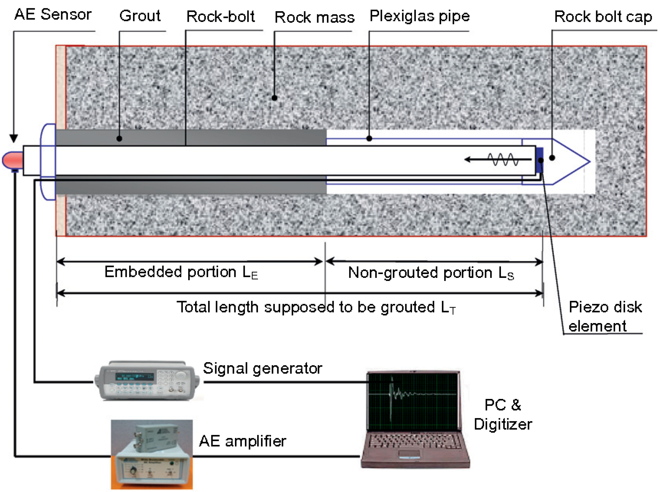
In 2012, In-Mo Lee et al. used piezo disk elements to generate ultrasonic waves and acoustic emission (AE) sensors to measure reflected waves (Figure 1) which were then analyzed by means of Fourier and wavelet transforms [13]. Their investigation examined different defective rock bolts using guided ultrasonic waves. The wavelet transform was found to be more sensitive to changes in the defect ratio. Energy leakages of the ultrasonic waves were also investigated in their study. Apparent attenuation and geometrical spreading are the main sources of wave amplitude decay in a rock bolt system [13].
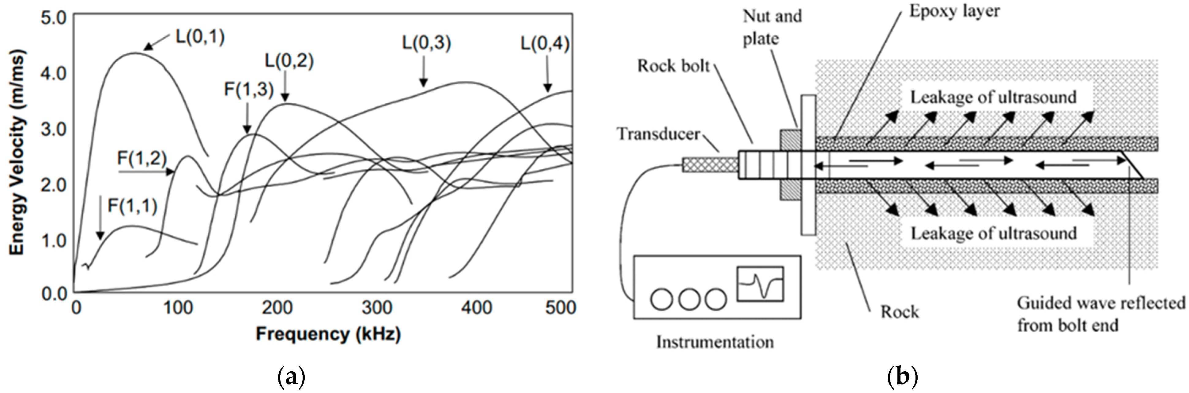
Knowledge of the wave velocity dispersion curves (Figure 2a)allows the position of defects or the bolt length to be calculated more accurately from the reflection arrival times [14]. Guided waves are used in these experiments to reduce changes in the shape of the signals as they propagate. Guided waves are subjected to both reflection and refraction inside solids (Figure 2b) and can include (a) compression, shear, and surface waves, (b) only mode-converted shear waves, (c) surface waves guided by a guide tool, and (d) surface lamb waves. This further complicates the use of ultrasonic waves for the inspection of rock bolts and pipes as the guided wave energy can travel in different modes, which are normally dispersive [15].
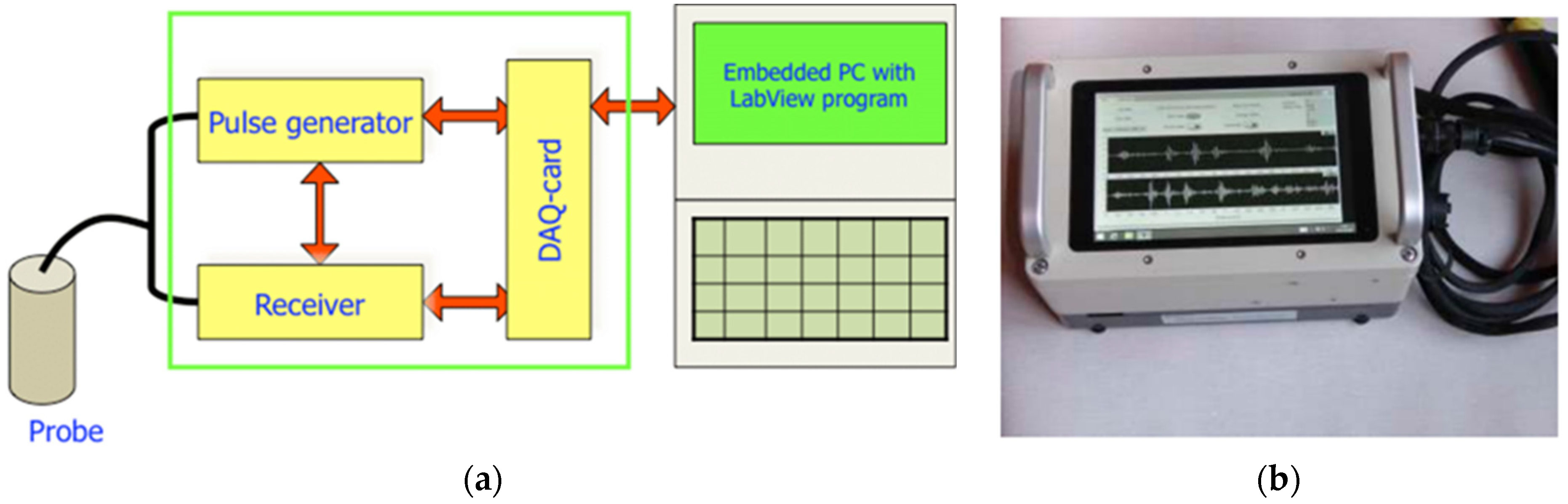
In recent years, several researchers have utilized the RBT (Rock Bolt Tester) instrument to study rock bolts nondestructively (Figure 3b). RBT is a portable instrument capable of generating and recording guided waves and an embedded digital computer for signal processing, operator communication, and data storage [15]. Stepinski et al. evaluated the use of RBT for inspecting 65 rock bolts [15]. As shown in Figure 3a, the instrument consists of a pulse signal generator, signal receiver, and DAQ card for digitizing analog signals to communicate with a computer. The pulse generator can produce two different types of pulses (compressional and quasi-flexural) which then travel through the rock bolts and reflect back. The reflected signals are detected by the receiver, then passed through a signal conditioner and data acquisition board, as shown in the Figure 3a. The authors conducted approximately 3200 tests on 65 rock bolts over the span of 37 months. According to the authors, the RBT instrument provided reliable estimates for the length of the rock bolts and successfully located artificially introduced voids in the grout. However, a rock bolt means wave velocity of 3000 m/s was assumed in the calculations.
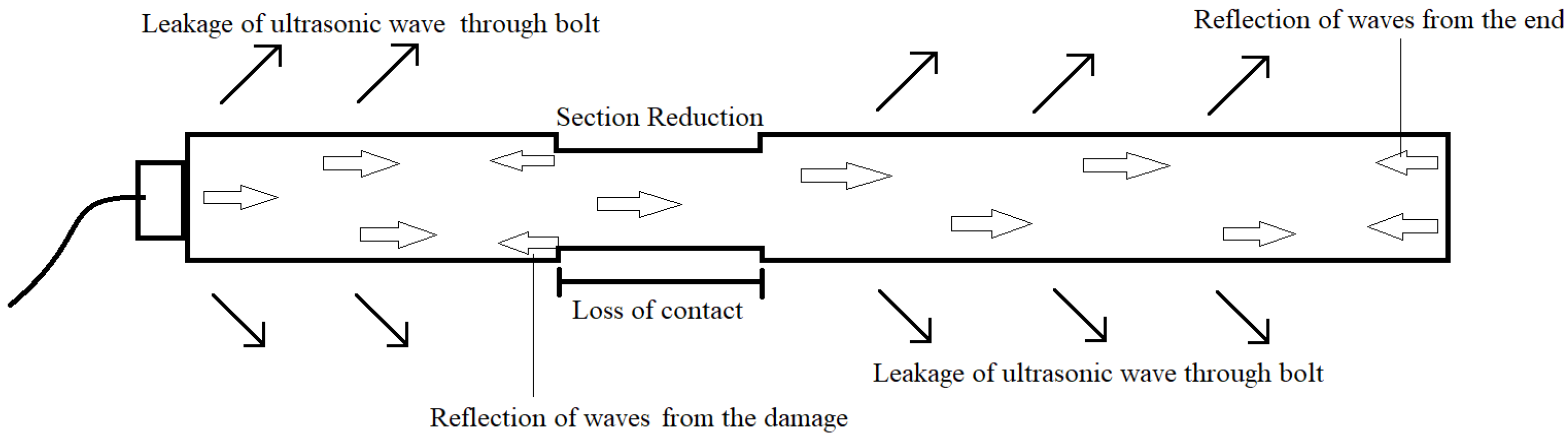
More recently, Taras et al. studied corrosion in rock bolts with the aid of waveguides (Figure 4) [16]. They successfully developed a wave energy propagation model for the analysis of ultrasonic waves based on reflected waves caused by the presence of defects. The defects were created artificially to simulate corrosion as in the real world. More specifically, three techniques were used to simulate corrosion in rock bolts. These techniques include tapering sections of rock bolts (thinning of the rock bolt over a certain length), loss of contact, and crack generation in the rock bolt. Cracks up to 8 mm were introduced in rock bolts. Additionally, as much as 12 mm of radial thickness was removed over approximately 15 cm of the rock bolt’s length for the tapered reduction case. The ultrasonic waves were found to be reflected whether from the end of the rock bolt or due to the defects caused by corrosion as demonstrated in the picture below.
Reflection coefficients were used by the researchers to detect and differentiate between the causes of reflected waves. A value of reflection coefficient close to unity (>0.90) indicated that most of the energy was reflected from the end of the bolt. Moreover, a value for the reflection coefficient within the range of 0.18 to 0.30, was indicative of the presence of voids or defects caused by corrosion. However, the variability in the measurements is within a range of 10% to 15%. This variance is the result of measuring the Δt of the arrival time of reflected waves. The energy of the reflected waves was used to calculate the coefficient of end reflection. The calculated values for reflection coefficients were used to determine the length of the rock bolts, tapered reduction (defects), and cracks in the rock bolts [16].
Zou et al. studied grout quality and its impact on guided ultrasonic waves [7]. They found that for the non-grouted bolts and the grouted bolts with low grout strength, the recorded wave signals had a high signal-to-noise ratio and data processing was simple. However, when both the grout strength and signal attenuation were high, the recorded signals became noisy, making data analysis more difficult.
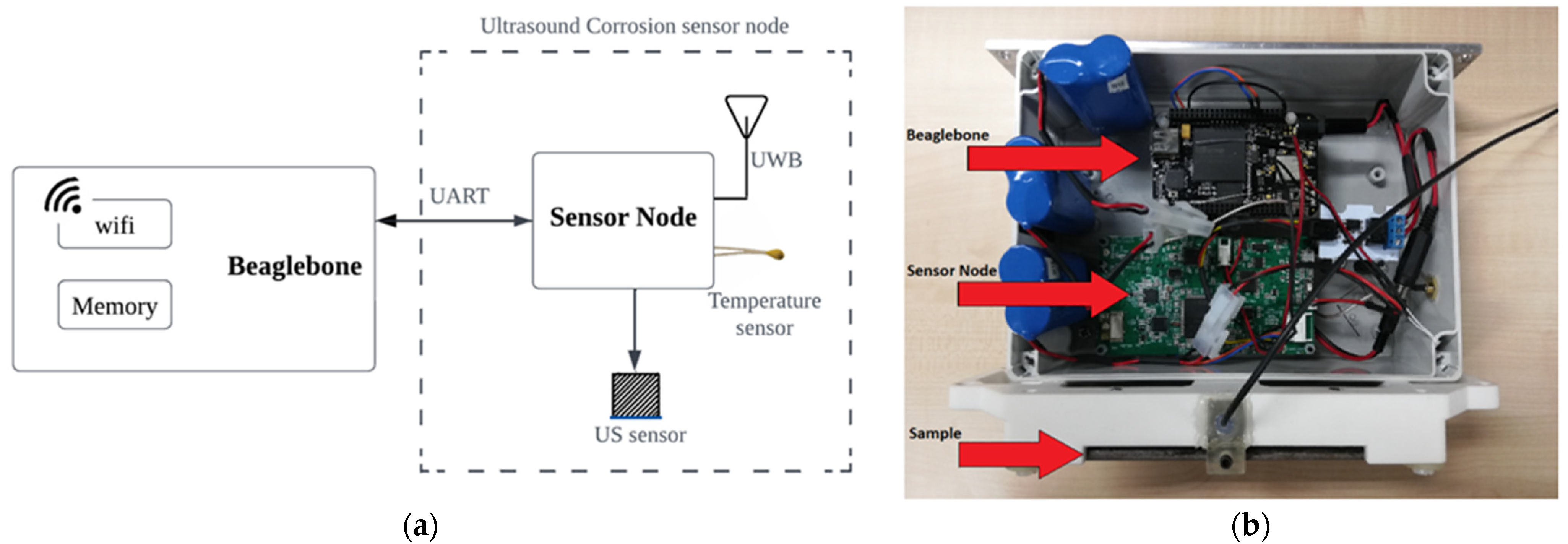
The modern approach to identifying and quantifying the degree of corrosion makes good use of remote data logging techniques. Thibbotuwa et al. in 2022 used a battery-powered corrosion monitoring setup that collected data every 6 h (Figure 5) [12]. The setup was installed in Gran Canaria coastal area for about six months. Thickness loss of a 5 mm steel sample was monitored over time in a highly corrosive offshore environment. Furthermore, over a period of 6 months, the ToF method was used to keep track of the reduction of plate thickness (the original dimension was 75 × 150 × 5 mm). The reduction of the plate thickness was the result of continuous corrosion which was calculated to occur at a rate of 0.134 mm/year. To reduce the computational complexity and to increase the accuracy of the ToF technique, parabolic interpolation was performed for the estimation of the location of the cross-correlation function peak. However, temperature correction had to be made for the collected data. Ultimately, the corrosion rate was calculated using the change in the amplitude of the ultrasonic signals.
2.1.2. Fiber Optic
Fiber optics is another method of studying rock bolts that has been gaining popularity in recent years. Fiber optic sensors are known to have the capability of measuring strain in the range of 0.01% to 1.5%. Two types of fiber optic sensors are FBG (Fiber Bragg Grating) and BOTMR (Brillouin Optical Time Domain Reflectometer) sensors. FBG sensors are simple to manufacture by UV imprinting of a grating pattern directly onto the fiber; the sensor diameter is the same as the fiber diameter; several different FBG sensors can be imprinted at distinct locations on the same fiber and can be individually addressed and multiplexed [17].
In the past decades, fiber optic sensor techniques have been developed from the experimental stage to practical applications. For instance, distributed fiber optic sensors were installed in dams and bridges to monitor the internal deformation of concrete at these facilities [18]. The optical interrogator sends a spectrum of light over the fiber optic cable in wavelengths ranging from 1500 to 1600 nm (Figure 6). A Bragg grating is a short piece of optical fiber that contains a pattern of several reflection points that causes certain wavelengths of incident light to reflect. The reflector is created by intense UV light affecting the fiber core. A fiber Bragg grating’s reflection spots are always equally spaced apart from one another. The grating reflects the wavelength that precisely corresponds to the separation between two reflection sites. The grating transmits all other wavelengths without reflection or dampening. Sensor signals from fiber Bragg gratings are the narrow spectrum that is reflected at each grating. The interrogator calculates the wavelength of each reflected peak. For instance, when a fiber Bragg grating is strained, the distance between the reflection sites shifts, and a new wavelength is reflected. This makes it possible to calculate the Bragg Wavelength variation similar to a metal strain gauge.
The Bragg Wavelength can be used to study the strain acting on the fiber optics cable as the wavelength increases with the increase in strain in the optic cable. Strain induces a positive change in the distance between the reflectors and as a result, an increase in wavelength is observed.
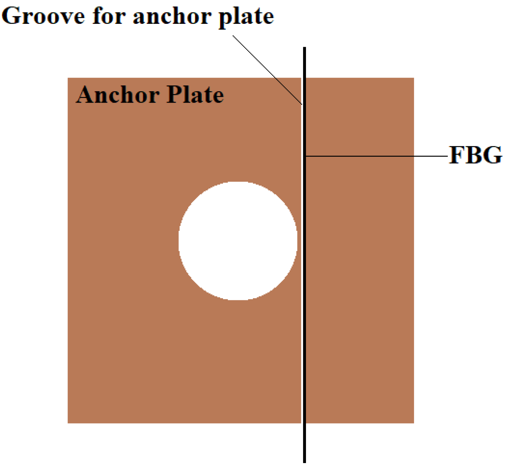
Sui et al. used the fiber Bragg sensor in the anchor pate where a 2 mm V-shaped groove was created to attach the sensor using adhesives as shown in Figure 7 [20]. The load experienced by the rock bolt anchor plate was calculated and it was demonstrated that the sensor in the anchor plate can measure the loading level past the yielding point of the plate itself.
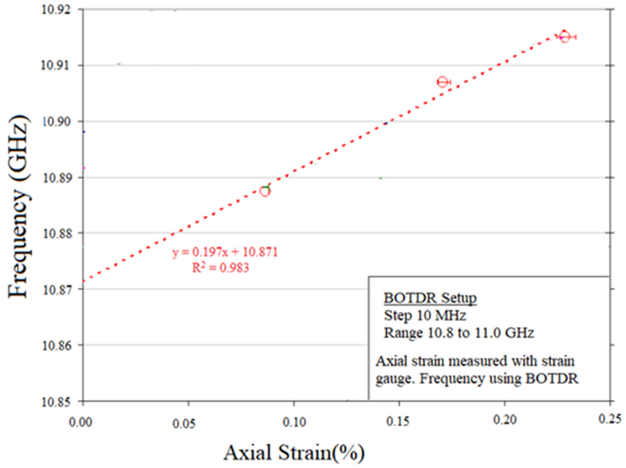
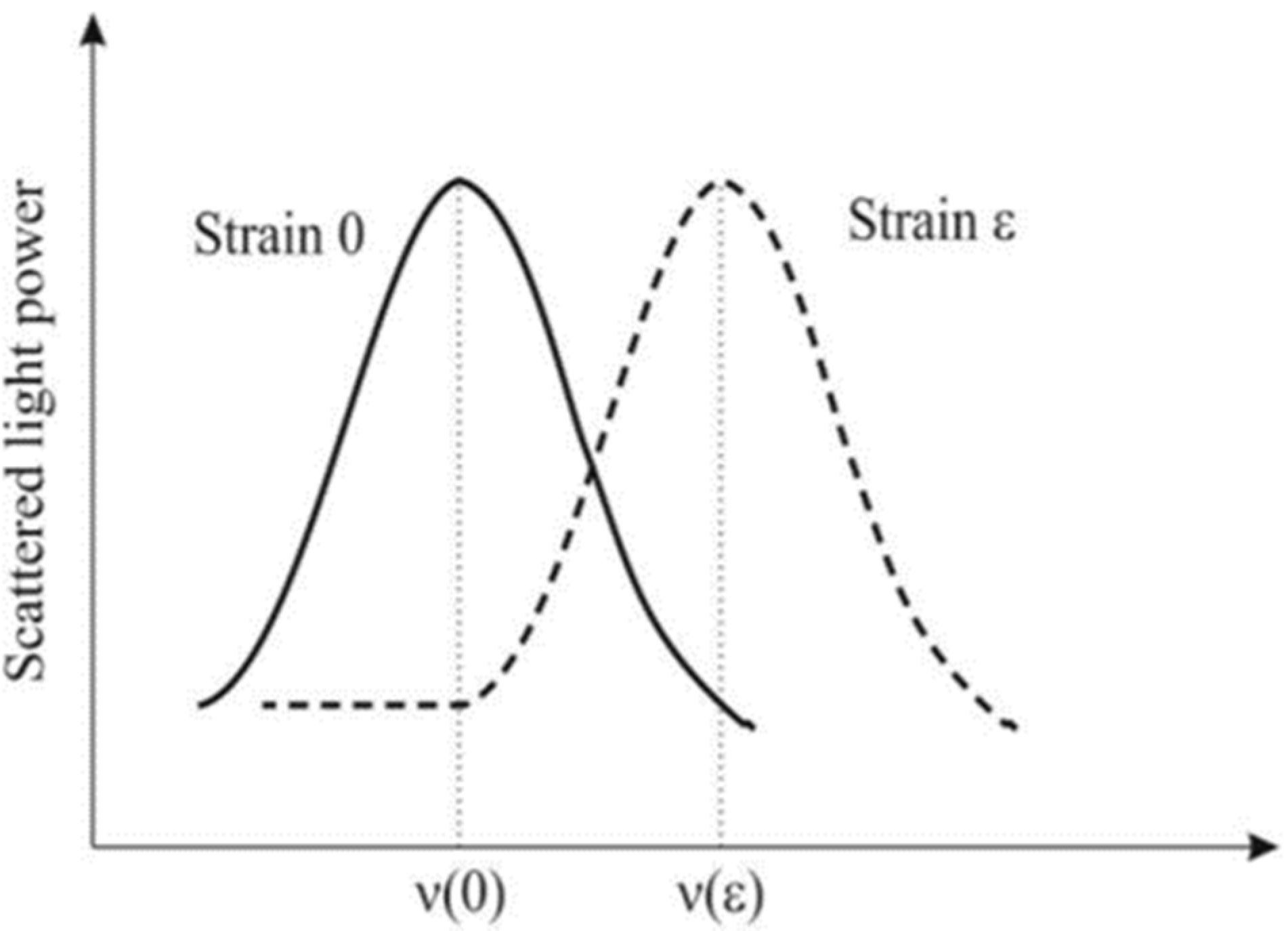
Furthermore, other researchers like Ricardo et al. have made use of a different type of fiber optics sensor known as BOTDR (Brillouin Optical Time Domain Reflectometer) [21]. Unlike the fiber Bragg sensor which measures the wavelength of the reflected Bragg wavelength, BOTDR measures the change in frequency of light that travels through the optical fiber as the optic fiber is subjected to strain. Traditional strain gauges were used by these researchers to measure the change in the strain which they correlated with the data from the BOTDR sensor as shown in Figure 8. A linear relationship was observed between the frequency and strain with a slope of 0.5. Figure 9 shows that the frequency of light increases with an increase in strain on the fiber optic cable.
2.1.3. Piezoelectric
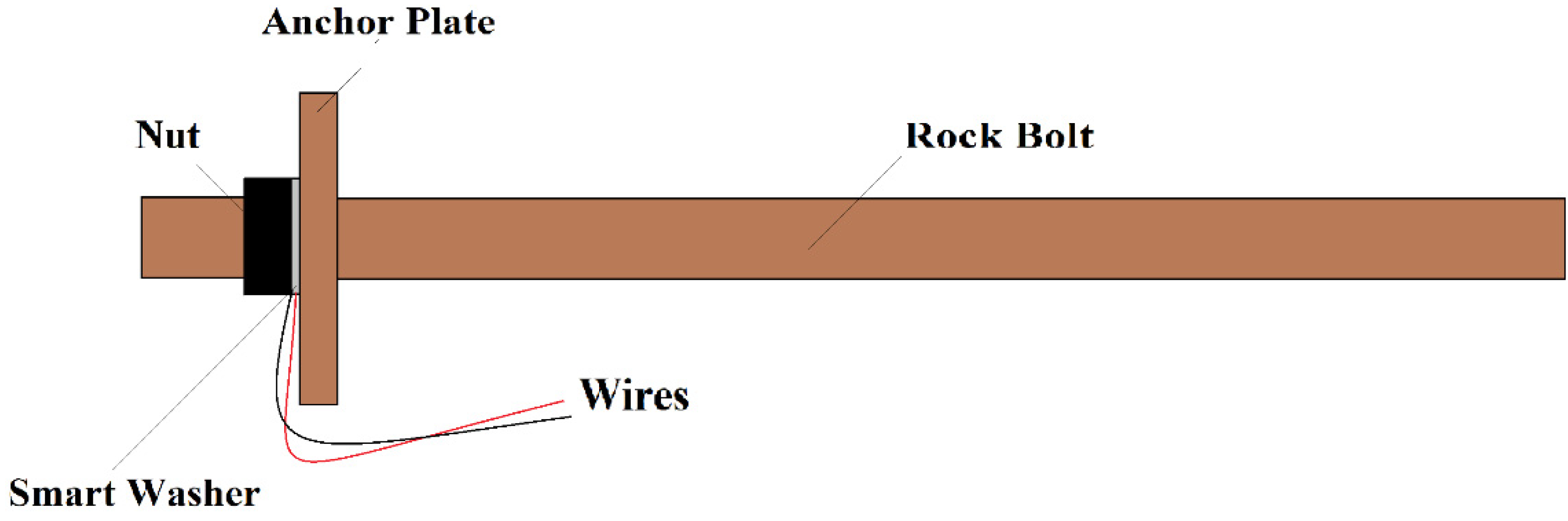
Piezoelectric methods have mostly been used to measure the looseness of rock bolts. The working principle is based on the idea that when the stress on a piezoelectrical material is removed, electric charges are produced. Wang et al., with the help of a piezoceramic material, developed smart washers that can be installed on the rock bolt as shown in Figure 10 [22]. PZT (lead–zirconate–titanate) based material was used to induce charge as the result of the piezoelectric effect. The smart washer was installed on the pre-tensioned (about 30 MPa) bolt and then the stress was decreased to simulate the loss of stress as if installed in a rock mass. To simplify the data interpretation, a normalized root mean square deviation (RMSD) index was used by the researchers to normalize the rock bolt looseness and hence the index of rock bolt looseness is set to be from 0 to 1. Reduction of the applied forces showed a decrease in the index and vice versa.
2.1.4. Numerical Methods
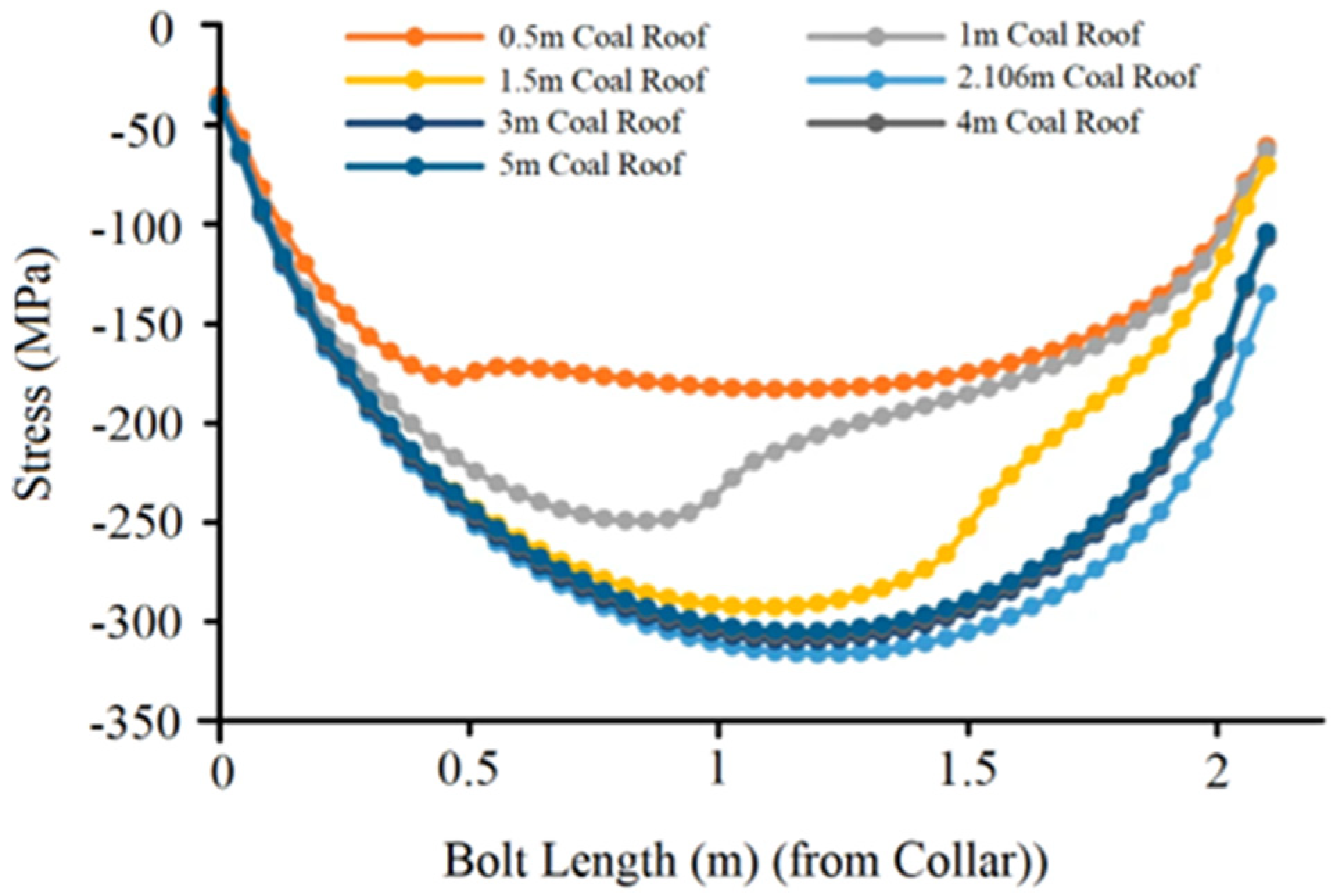
Efforts have been made to understand the phenomenon of rock bolt failure known as SCC (Stress Corrosion Cracking) [23]. Stress corrosion cracking causes the rock bolts to fail in a brittle manner at a strength lesser than their ultimate tensile strength. SCC is mostly initiated by the presence of groundwater with higher corrosivity, but it can also occur in low-corrosivity groundwater because of the presence of microbial organisms, in particular, sulfate-reducing bacteria [24]. Jack et al. used numerical modeling to study the impact of groundwater and tensile stress on the rock bolts, especially focusing on the ones used for the underground coal mine [24]. Using Rockscience’s 3D finite element software, it was determined that the increase in groundwater flow had a direct effect on the bolt’s failure and that the largest tensile stress occurred along the length of the bolt as the coal roof’s thickness grew. Furthermore, the authors suggested that exposure of the rock bolt to the groundwater can be reduced by controlling the loss of grout while installing the rock bolt and minimizing the fracturing in the grout. A study of the presence of voids (trapped bubbles) or microcracks in the grout–resulting from improper installation could also provide vital information about the health of a rock bolt. Defects in the grout could let groundwater seep through and come into contact with the rock bolts.
Figure 11 explains that the tensile strength is the maximum at the center of the bolt length between the top and the bottom. Additionally, hence, the decision of fully or partially grouting the rock bolt matters in order to minimize the failure of the rock bolt due to stress corrosion cracking.
2.1.5. Electromagnetic
Although the ultrasonic sensor technology for the detection of corrosion in rock bolts is a popular method, there are a few drawbacks associated with it. A major downside is that if the rock bolt is curved then the wave attenuation could become higher and hence the propagation energy tends to leak from the rock bolt [25]. Moreover, the equipment required to generate high-quality signals, such as wave generators and amplifiers, is costly, and expert skills are required for signal analysis [14].
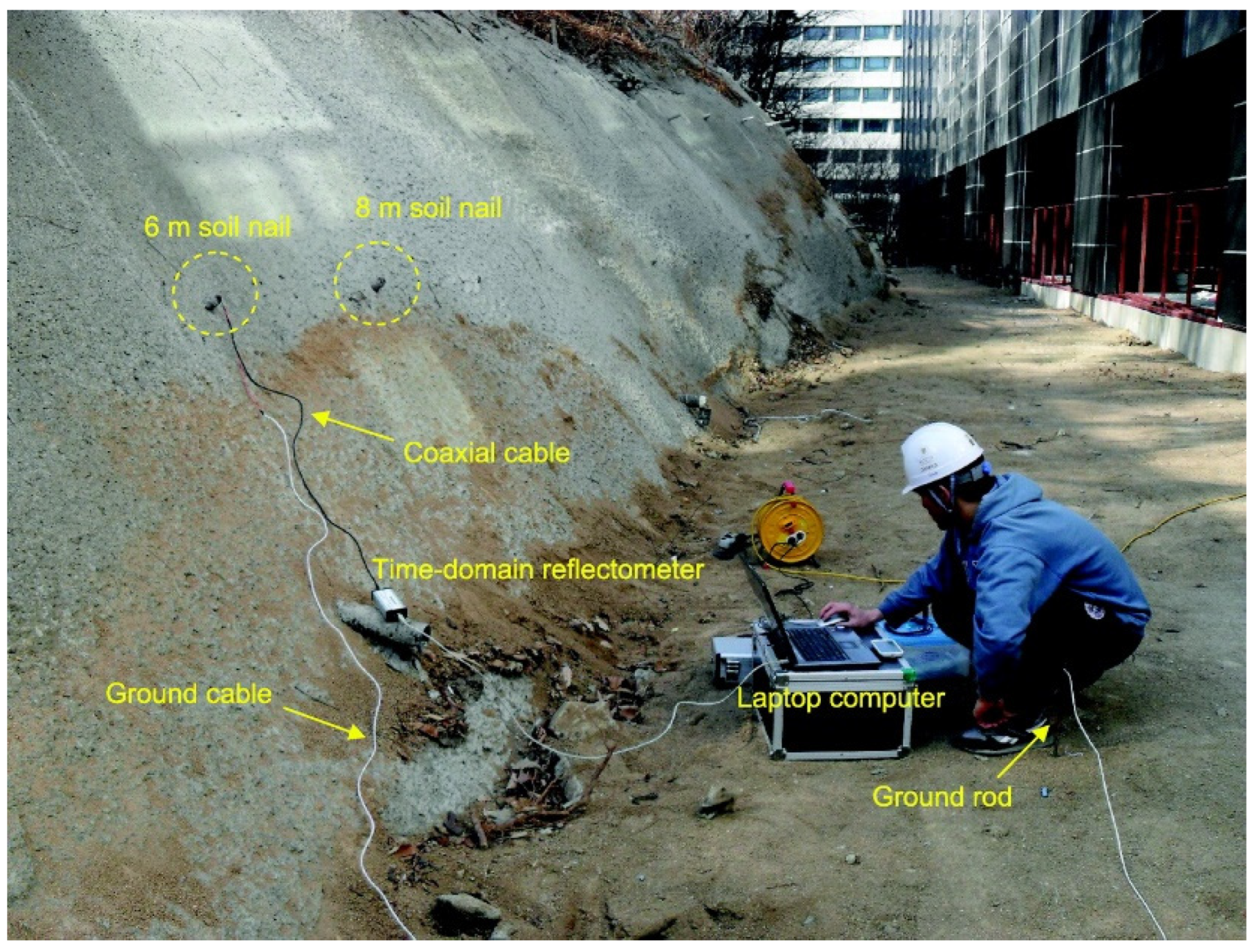
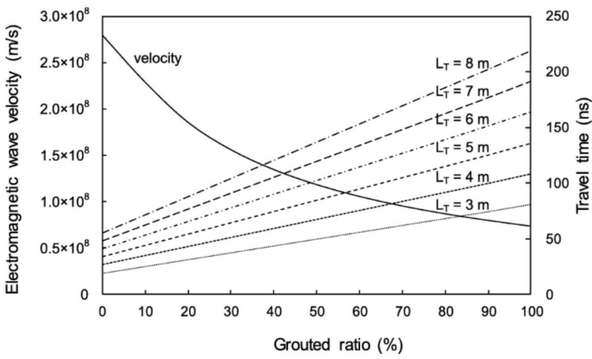
Jung et al. studied the application of electromagnetic waves for monitoring the health of soil nails [26]. Soil nails are similar to steel studs, but they are installed in soil slopes for stability. Rock bolts are generally pre-stressed whereas soil nails are not. A time-domain reflectometer (TDR) was used to generate electromagnetic waves and experiments were conducted on steel bars (partially grouted, fully grouted, and not grouted). The setup for this research is displayed in Figure 12. It was observed that the method of using electromagnetic waves for monitoring the health of installed soil nails can be useful. Furthermore, it was noticed that the velocity of the electromagnetic wave decreases with the increasing percentage of grouts present in the steel bar (Figure 13).
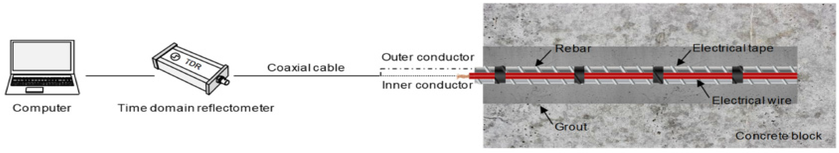
In 2020, Jung Yu and Jong Lee introduced the use of electromagnetic waves to study defects in rock bolts with a simple and low-cost method [2]. Experiments were performed on embedded and non-embedded rock bolts. Embedded conditions simulate the real-world condition where the rock bolt is inserted into the rock mass whereas non-embedded is the condition where the rock bolt was only enveloped in the cement grout. TDR was used to generate and detect electromagnetic waves. The authors demonstrated that the electromagnetic waves were reflected both at the end and head of the rock bolts, as well as all the voids located in the rock bolt. However, for this method to work, as shown in Figure 14, electrical wires should be installed along the length of the rock bolt. The permanent monitoring of rock bolts can then be accomplished if there is no damage to the wire due to deformation and weathering.
2.1.6. Impact-Echo
The Impact-Echo (IE) method uses stress waves to interrogate and evaluate both the length as well as the health of the rock bolt grouts. Similar to ultrasonic and electromagnetic techniques, the energy generated by the impactor travels through the material as stress waves and is reflected and scattered when they encounter an interface of sufficiently different impedance. If the dynamic load is applied to the rock bolt, particles within the rock bolt show compressive and dilative behavior in the longitudinal direction which is also called P waves, and the propagation of such waves can be detected and recorded [27].
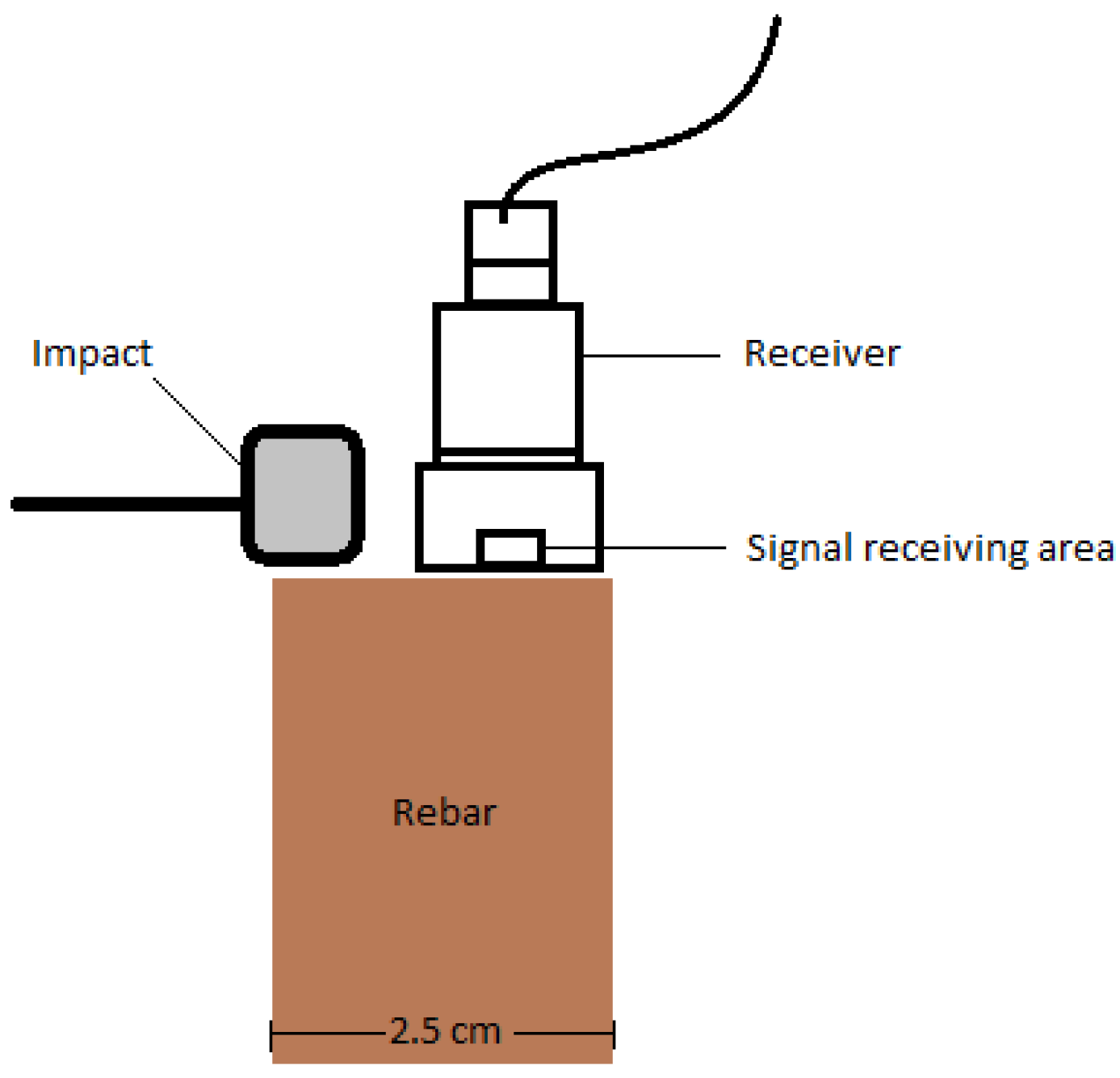
Yu Feng et al. in 2022, used the impact echo method to determine the length of rock bolts (Figure 15) [27]. The impactor and receiver were placed at one end of the rock bolt to collect the data. This arrangement is practical for field applications. The effectiveness of the impact-echo method was studied in both grouted and ungrouted rock specimens. The diameter of the receiver is 2 cm and the diameter of the signal receiving area is 1 mm over the rebar, which has a diameter of 2.5 cm. Analysis of the spectral response of the rock bolt in the air and the soil showed no discernible difference. The reason was attributed to the lower stiffness of the soil compared to that of the steel bar, and the lack of cohesion in the soil particles.
2.1.7. Acoustic Emission
Corrosion can act as a main cause of structural degradation and initiate the process of fracture and disbonding which leads to acoustic emissions [28]. The acoustic emission (AE) method monitors and records acoustic waves which can be correlated to the associated corrosion present in the rock bolt. The acoustic emission method is a non-invasive technique for the inspection of structures subject to the external load and/or internal damage. Sensors are placed on available surfaces such as the ends of rock bolts, end plates, or attached to the rock bolts. Corrosion inside and outside the element or under the insulation was detected and monitored [29]. A common method of AE-based monitoring uses piezoelectric sensors, amplifiers, and filters [30]. The major disadvantage of using acoustic emission for the study of corrosion is that it is not a one-time measurement and data must be collected over time to get the desired outcome. Additionally, the results are difficult to interpret and quantified into a reliable index indicating the degree of corrosion in the rock bolt. Because acoustic emission signals are usually very weak, in a noisy environment, the process of noise reduction and signal discrimination can be extremely problematic [30].
In 2017, Medfouni et al. used the acoustic emission method for studying corroded rock bolts (Figure 16) [31]. A micro-SAMOS device from Physical Acoustic Corporation (PAC) comprised of a piezoelectric sensor, full waveform capture, and the AEwin software was used to collect the AE data. The threshold for the cumulative AE counts was set to 35 dB and the number of times those signals cross the detection threshold was determined. Furthermore, the tests were performed on four blocks out of which three were subjected to accelerated corrosion, and the fourth block was kept intact as the baseline, and to filter the noise. The study investigated the acoustic emission cumulative frequency in corroded and non-corroded rock bolts. Furthermore, sensors were attached to both the concrete blocks and the rock bolts, and the signals were analyzed and compared with each other. It was observed that the cumulative increase in AE counts showed a direct correlation with the increase in corrosion from the concrete blocks and the expansion of cracks in the concrete. The authors concluded that the AE method can be used to assess corrosion in rock bolts.
3. Discussion
Non-destructive testing (NDT) and in situ methods for the inspection of rock bolts have been undergoing rapid development in the last decade. The alternative, that is, the pullout (destructive) tests are more time-consuming, costly, irreversible, and cumbersome to perform. Rock bolts are used for the purpose of providing stability in engineering structures such as tunnels and underground mines. The use of NDT can help monitor the condition of rock bolts affected by external parameters such as corrosion. Corrosion can significantly reduce the strength of the rock bolt and its load-bearing capacity in a ground support system.
A review of the literature on nondestructive testing of rock bolts shows that techniques such as ultrasonic, fiber optic, piezoelectric, numerical, electromagnetic, impact echo, and acoustic emission have been used by researchers around the world. However, only two methods, namely the ultrasonic and the acoustic emission methods are suitable for locating corrosion in an installed rock bolt directly. The numerical analysis approach can also be used as an indirect probabilistic method to estimate if the rock bolt will undergo corrosion. Numerical analysis methods are beneficial for determining the rate of corrosion in rock bolts over a certain period of time. This method of analysis can be used to create simulations of the environment in which the bolts are installed and to predict the level of corrosion that is likely to occur. While the accuracy of numerical analysis methods has yet to be verified, they offer a cost-effective and time-saving way to gain insight into potential corrosion rates.
As shown in Table 1, the NDT methods for the study of rock bolts can be subdivided into three distinct types depending upon the characteristics and conditions they intend to inspect, test, or evaluate.
3.1. NDT for the Study of Strain
The fiber optic method can help accurately monitor changes in the deformation along the length of rock bolts. However, they can only be used when installing new rock bolts. A reliable method should be devised to mount FBG sensors into the rock bolts before the installation. Ultrasonic, piezoelectric, electromagnetic wave method, and the impact echo method can also be used to determine the length of the rock bolt over time, but the tests require operator intervention. A skilled operator is required to collect data manually from each rock bolt at predetermined time intervals. This can be a very repetitive and time-consuming task to perform depending upon the number of rock bolts that need to be monitored. However, the FBG method can be automated. The FBG sensors provide flexibility for remote data collection. Since the FBG sensor is directly attached to the rock bolt, there is less risk of mistakes and incorrect interpretation of data compared to other methods. On the other hand, techniques such as ultrasonic are more practical for studying corrosion in an installed rock bolt. When using the piezoelectric method, sensors are installed on the anchor plate prior to installation and like the fiber optic method, they cannot be used on an installed rock bolt.
3.2. NDT for the Study of Corrosion
One of the biggest challenges in detecting corrosion in an installed rock bolt is the limited exposure of the rock bolt. Corrosion is difficult to identify and quantify in the field because only a short section of the bolt is available for measurement. To investigate corrosion in an installed rock bolt, ultrasonic and acoustic emission methods have been used by researchers in the past. Even though the ultrasonic and acoustic emission methods have been successfully used to locate the corrosion in rock bolts, previous research provides very little information on the type of these monitoring systems and existing conditions under which rock bolts have been tested. A detailed study on the effect of the rock bolt diameter and bent rock bolt on the quality of ultrasonic and acoustic emission data can be very useful. Moreover, previous studies have focused mainly on grouted and non-grouted rebars and bolts. It would be beneficial to conduct similar studies on other types of frictional (Split set, Swellex rock bolt) and cable rock bolts, which are equally used in the industry and are also susceptible to corrosion. In addition to the ultrasonic and acoustic emission techniques, numerical methods provide an indirect approach for the study of corrosion where models are built and tested using computational models.
3.3. NDT for the Study of Grouts
The strength and proper setting of the grouting material around the rock bolt are of prime importance with respect to the long-term health condition and durability of the rock bolts. Because grout could act as a preventive shield against corrosion and provides additional frictional resistance to keep the rock bolt in place and intact, a study on the response of different types of grouting materials is also an important aspect of monitoring rock bolts. Electromagnetic and ultrasonic methods are used for assessing the condition of the grout around rock bolts. The electromagnetic methods reported in this paper require the placement of a coaxial cable inside the grouts during the installation. Once the installation is completed, reliable data can be collected with ease. This makes the electromagnetic method more advantageous than the ultrasonic method for monitoring and evaluating the grout condition. Both the ultrasonic and electromagnetic methods can be used to determine the relative dimension and location of disbonding or voids in the grout.
4. Conclusions
Upon further analysis of the literature, as shown in Table 2 below, we can see the research on non-destructive testing methods is clustered in countries with a long history of underground mining and tunneling expertise. The application of NDT methods for rock bolt evaluation as early as 2001 in the United States. The growth of research activities in this field is directly related to the need for monitoring and maintaining the aging infrastructure in the countries listed in Table 2 (and other countries) along with advances made in sensor development. Because rock bolts are used in many engineering fields such as civil, tunneling, and mining, as a primary tool for creating a safe environment underground, it has become imperative to reliably evaluate the state of the installed rock bolts before they fail. A corroded rock bolt will have a reduced tensile strength and ultimately a lower load-bearing capacity. Weakened or damaged rock bolts could cause a failure in underground structures costing both capital and lives. With the development of more advanced NDT methods, they can be used individually or in combination to provide a comprehensive evaluation of the condition of rock bolts. This can be of great aid to mining operations allowing for more timely scheduling of inspection and maintenance tasks.
Although research into characterizing the damage on installed rock bolts has made great strides, there is one major drawback—the majority of monitoring methods are only applicable to rebar bolts. We must recognize that rebar bolts are just one type of rock bolt used in the industry, with cable bolts being a more common choice for underground projects. Unfortunately, rock bolts are more vulnerable to corrosion because groundwater and high temperatures are more prevalent in many underground mining operations.
It is time to take a more in-depth look at the connection that exists between the amount of corrosion that has taken place and the load-bearing capacity of rock bolts. The procedures that are now used in the industry do not appear to take into account this vital connection but having a grasp of it could be the key to unlocking the potential for preventing ground failure.
Author Contributions
Writing—original draft preparation, B.L., writing—review and editing, M.M. All authors have read and agreed to the published version of the manuscript.
Funding
This research received no external funding.
Data Availability Statement
Not applicable.
Acknowledgments
We thank the University of Arizona for providing access to journal publications and databases for conducting the literature search.
Conflicts of Interest
The authors declare no conflict of interest.
References
- Luo, M.; Li, W.; Wang, B.; Fu, Q.; Song, G. Measurement of the Length of Installed Rock Bolt Based on Stress Wave Reflection by Using a Giant Magnetostrictive (GMS) Actuator and a PZT Sensor. Sensors 2017, 17, 444. [Google Scholar] [CrossRef] [Green Version]
- Yu, J.-D.; Lee, J.-S. Smart Sensing Using Electromagnetic Waves for Inspection of Defects in Rock Bolts. Sensors 2020, 20, 2821. [Google Scholar] [CrossRef] [PubMed]
- Song, G.; Li, W.; Wang, B.; Ho, S.C. A Review of Rock Bolt Monitoring Using Smart Sensors. Sensors 2017, 17, 776. [Google Scholar] [CrossRef] [PubMed] [Green Version]
- Yan, S.; Song, Y.; Bai, J.; Elmo, D. A Study on the Failure of Resin End-Anchored Rockbolts Subjected to Tensile Load. Rock Mech. Rock Eng. 2018, 52, 1917–1930. [Google Scholar] [CrossRef]
- Craig, P.; Serkan, S.; Hagan, P.; Hebblewhite, B.; Vandermaat, D.; Crosky, A.; Elias, E. Investigations into the corrosive environments contributing to premature failure of Australian coal mine rock bolts. Int. J. Min. Sci. Technol. 2016, 26, 59–64. [Google Scholar] [CrossRef]
- Zou, D.; Cui, Y. A new approach for field instrumentation in grouted rock bolt monitoring using guided ultrasonicwaves. J. Appl. Geophys. 2011, 75, 506–512. [Google Scholar] [CrossRef]
- Zou, D.S.; Cheng, J.; Yue, R.; Sun, X. Grout quality and its impact on guided ultrasonic waves in grouted rock bolts. J. Appl. Geophys. 2010, 72, 102–106. [Google Scholar] [CrossRef]
- Cui, Y.; Zou, D. Assessing the effects of insufficient rebar and missing grout in grouted rock bolts using guided ultrasonic waves. J. Appl. Geophys. 2012, 79, 64–70. [Google Scholar] [CrossRef]
- Yu, J.-D.; Bae, M.-H.; Lee, I.-M.; Lee, J.-S. Nongrouted ratio evaluation of rock bolts by reflection of guided ultrasonic waves. J. Geotech. Geoenviron. Eng. 2012, 139, 298–307. [Google Scholar] [CrossRef]
- Madenga, V.; Zou, D.; Zhang, C. Effects of curing time and frequency on ultrasonic wave velocity in grouted rock bolts. J. Appl. Geophys. 2006, 59, 79–87. [Google Scholar] [CrossRef]
- Wang, C.; He, W.; Ning, J.; Zhang, C. Propagation properties of guided wave in the anchorage structure of rock bolts. J. Appl. Geophys. 2009, 69, 131–139. [Google Scholar] [CrossRef]
- Thibbotuwa, U.C.; Cortés, A.; Irizar, A. Small Ultrasound-Based Corrosion Sensor for Intraday Corrosion Rate Estimation. Sensors 2022, 22, 8451. [Google Scholar] [CrossRef]
- Lee, I.-M.; Han, S.-I.; Kim, H.-J.; Yu, J.-D.; Min, B.-K.; Lee, J.-S. Evaluation of rock bolt integrity using Fourier and wavelet transforms. Tunn. Undergr. Space Technol. 2012, 28, 304–314. [Google Scholar] [CrossRef]
- Beard, M.; Lowe, M. Non-destructive testing of rock bolts using guided ultrasonic waves. Int. J. Rock Mech. Min. Sci. 2003, 40, 527–536. [Google Scholar] [CrossRef]
- Stepinski, T.; Matsson, K. Rock Bolt Inspection by Means of RBT Instrument. In Proceedings of the 19th World Conference on Non-Destructive Testing 2016, Munich, Germany, 13–17 June 2016. [Google Scholar]
- Taras, A.; Saleh, K. Non-Destructive Inspection of Corrosion in Rock Bolts Using an Ultrasonic Waveguide Approach. In Proceedings of the 13th International Conference on Damage Assessment of Structures; Lecture Notes in Mechanical Engineering. Wahab, M., Ed.; Springer: Singapore, 2020. [Google Scholar] [CrossRef]
- Giurgiutiu, V. 17—Structural health monitoring (SHM) of aerospace composites. In Woodhead Publishing Series in Composites Science and Engineering, Polymer Composites in the Aerospace Industry, 2nd ed.; Irving, P., Soutis, C., Eds.; Woodhead Publishing: Sawston, UK, 2020; pp. 491–558. ISBN 9780081026793. [Google Scholar] [CrossRef]
- Bai, Y.; Bai, Q. Chapter 7—Fiber Optic Monitoring System. In Subsea Pipeline Integrity and Risk Management; Bai, Y., Bai, Q., Eds.; Gulf Professional Publishing: Houston, TX, USA, 2014; pp. 145–165. Available online: https://www.sciencedirect.com/science/article/pii/B978012394432000007X (accessed on 10 September 2022). [CrossRef]
- FBGS: FBG Sensor Principle. 2022. Available online: https://fbgs.com/ (accessed on 15 March 2022).
- Ho, S.C.M.; Li, W.; Wang, B.; Song, G. A Load Measuring Anchor Plate for Rock Bolt Using Fiber Optic Sensor. Smart Mater. Struct. 2017, 26, 057003. [Google Scholar] [CrossRef]
- Moffat, R.A.; Beltran, J.F.; Herrera, R. Applications of BOTDR fiber optics to the monitoring of underground structures. Geo-Mech. Eng. 2015, 9, 397–414. [Google Scholar] [CrossRef]
- Wang, B.; Huo, L.; Chen, D.; Li, W.; Song, G. Impedance-Based Pre-Stress Monitoring of Rock Bolts Using a Piezoceramic-Based Smart Washer—A Feasibility Study. Sensors 2017, 17, 250. [Google Scholar] [CrossRef] [PubMed]
- Craig, P.; Ramandi, H.L.; Chen, H.H.; Vandermaat, D.; Crosky, A.; Hagan, P.; Hebblewhite, B.; Saydam, S. Stress corrosion cracking of rockbolts: An in-situ testing approach. Constr. Build. Mater. 2021, 269, 121275. [Google Scholar] [CrossRef]
- Smith, J.A.; Ramandi, H.L.; Zhang, C.; Timms, W. Analysis of the influence of groundwater and the stress regime on bolt behaviour in underground coal mines. Int. J. Coal Sci. Technol. 2019, 6, 286–300. [Google Scholar] [CrossRef] [Green Version]
- Beard, M.D.; Lowe, M.J.S.; Cawley, P. Inspection of rockbolts using guided ultrasonic waves. AIP Conf. Proc. 2001, 557, 1156–1163. [Google Scholar]
- Yu, J.-D.; Kim, K.-H.; Lee, J.-S. Nondestructive health monitoring of soil nails using electromagnetic waves. Can. Geotech. J. 2018, 55, 79–89. [Google Scholar] [CrossRef]
- Lin, Y.-F.; Ye, J.-W.; Lo, C.-M. Application of impact-echo method for rockbolt length detection. Constr. Build. Mater. 2022, 316, 125904. [Google Scholar] [CrossRef]
- Cole, P.; Watson, J. Acoustic emission for corrosion detection. In Proceedings of the Middle East Nondestructive Testing Conference & Exhibition, Manama, Bahrain, 27–30 November 2005; Available online: https://www.ndt.net/article/mendt2005/pdf/01.pdf (accessed on 3 August 2022).
- Tscheliesnig, P.; Lackner g Jagenbrein, A. Corrosion Detection by means of acoustic emission monitoring. In Proceedings of the 19th World Conference on Non-Destructive Testing 2016, Munich, Germany, 13–17 June 2016; Available online: https://www.ndt.net/article/wcndt2016/papers/th3d2.pdf (accessed on 5 September 2022).
- Light, G. 12—Nondestructive evaluation technologies for monitoring corrosion. In Woodhead Publishing Series in Metals and Surface Engineering, Techniques for Corrosion Monitoring; Yang, L., Ed.; Woodhead Publishing: Sawston, UK, 2008; pp. 293–312. ISBN 9781845691875. [Google Scholar]
- Billeh Ishak Medfouni, E.M.; Kodjo, A.S.; Rivard, P.; Saleh, K.; Quirion, M. Assessment of Corroded Rock Bolts with Pulse Echo Tests. J. Infrastruct. Syst. 2017, 23, 04017007. [Google Scholar] [CrossRef]
Figure 1.
Rock bolt integrity measurement system [13].
Figure 1.
Rock bolt integrity measurement system [13].

Figure 2.
(a) an example of energy velocity dispersion curves for the rock bolt model; (b) Schematic diagram of the rock bolt installation using guided waves inspection [14].
Figure 2.
(a) an example of energy velocity dispersion curves for the rock bolt model; (b) Schematic diagram of the rock bolt installation using guided waves inspection [14].

Figure 3.
(a) Block diagram of RBT instrument; (b) RBT [15].
Figure 3.
(a) Block diagram of RBT instrument; (b) RBT [15].

Figure 4.
Transmission, reflection, and leakage of the ultrasonic wave pulse through a bolt.

Figure 5.
Final electronics setup used in the experiment. (a) Block diagram of the setup; (b) photograph of the actual setup [12].
Figure 5.
Final electronics setup used in the experiment. (a) Block diagram of the setup; (b) photograph of the actual setup [12].

Figure 6.
(a)FBG sensor; (b) Working mechanism of FBG Sensor [19].
Figure 6.
(a)FBG sensor; (b) Working mechanism of FBG Sensor [19].

Figure 7.
FBG sensor installed on Anchor Plate.

Figure 8.
Correlation between average frequencies and strains measured by strain gauge [21].
Figure 8.
Correlation between average frequencies and strains measured by strain gauge [21].

Figure 9.
Brillouin Frequency shift [21].
Figure 9.
Brillouin Frequency shift [21].

Figure 10.
Design of smart washer in a rock bolt specimen.

Figure 11.
Distribution of stress in rock bolt [24].
Figure 11.
Distribution of stress in rock bolt [24].

Figure 12.
Experimental setup for electromagnetic wave [26].
Figure 12.
Experimental setup for electromagnetic wave [26].

Figure 13.
Wave velocity vs. time travel for soil nails in soil [26].
Figure 13.
Wave velocity vs. time travel for soil nails in soil [26].

Figure 14.
Smart sensing system for measuring electromagnetic waves in rock bolts [2].
Figure 14.
Smart sensing system for measuring electromagnetic waves in rock bolts [2].

Figure 15.
Configuration of Impact-echo experiment.

Figure 16.
Acoustic Emission setup [31].
Figure 16.
Acoustic Emission setup [31].


Table 1.
Understanding Non-Destructive Test.
| NDT for Strain Measurement | NDT for Detecting Corrosion | NDT for Study of Grouts |
|---|---|---|
| Ultrasonic method | Ultrasonic method | Electromagnetic method |
| Fiberoptic method | Acoustic Emission method | Ultrasonic method |
| Piezoelectric method | Numerical analysis | |
| Impact Echo method | ||
| Electromagnetic wave method |
Table 2.
Research progress in the field of corrosion in rock bolts.
| Research Progress | Country | Reference No. | Total Ref. |
|---|---|---|---|
 | USA | [1,2,3,17,18,22,25,30,31] | 9 |
 | China | [1,3,4,7,10,11,20,22] | 8 |
 | Canada | [4,6,8,10,16,26] | 6 |
 | Korea | [2,8,9,13] | 4 |
 | Australia | [5,23,24] | 3 |
 | England | [14,28] | 2 |
 | Sweden | [15] | 1 |
 | Poland | [15] | 1 |
 | Germany | [19] | 1 |
 | Taiwan | [27] | 1 |
 | Austria | [29] | 1 |
 | Spain | [12] | 1 |
 | Chile | [21] | 1 |
 |
Disclaimer/Publisher’s Note: The statements, opinions and data contained in all publications are solely those of the individual author(s) and contributor(s) and not of MDPI and/or the editor(s). MDPI and/or the editor(s) disclaim responsibility for any injury to people or property resulting from any ideas, methods, instructions or products referred to in the content. |
© 2023 by the authors. Licensee MDPI, Basel, Switzerland. This article is an open access article distributed under the terms and conditions of the Creative Commons Attribution (CC BY) license (https://creativecommons.org/licenses/by/4.0/).
Share and Cite
MDPI and ACS Style
Lama, B.; Momayez, M. Review of Non-Destructive Methods for Rock Bolts Condition Evaluation. Mining 2023, 3, 106-120. https://doi.org/10.3390/mining3010007
AMA Style
Lama B, Momayez M. Review of Non-Destructive Methods for Rock Bolts Condition Evaluation. Mining. 2023; 3(1):106-120. https://doi.org/10.3390/mining3010007
Chicago/Turabian StyleLama, Biraj, and Moe Momayez. 2023. "Review of Non-Destructive Methods for Rock Bolts Condition Evaluation" Mining 3, no. 1: 106-120. https://doi.org/10.3390/mining3010007