
Mineral Processing Techniques Dedicated to the Recycling of River Sediments to Produce Raw Materials for Construction Sector


Abstract
:1. Introduction
- Calcination: generally expensive (higher than 90 €/ton dry matter [DM]);
- Stabilisation/solidification: use of reactants, generally expensive (50–75 €/ton DM);
- Size classification: comprises a lot of steps (±30 €/ton DM);
- Flotation: use of expensive reactants (10–40 €/ton DM).
- Heavy metals can be stabilised using specific reactants, such as in the Novosol® process (treatment with phosphoric acid to synthesize apatite which retains some heavy metals followed by thermal treatment to reduce organic pollutant levels; [34]) or can be partially removed by froth flotation [35,36].
- Some crystalline phases can have unwanted effects, for example clayey swelling phases, but it can be removed by size classification or froth flotation techniques.
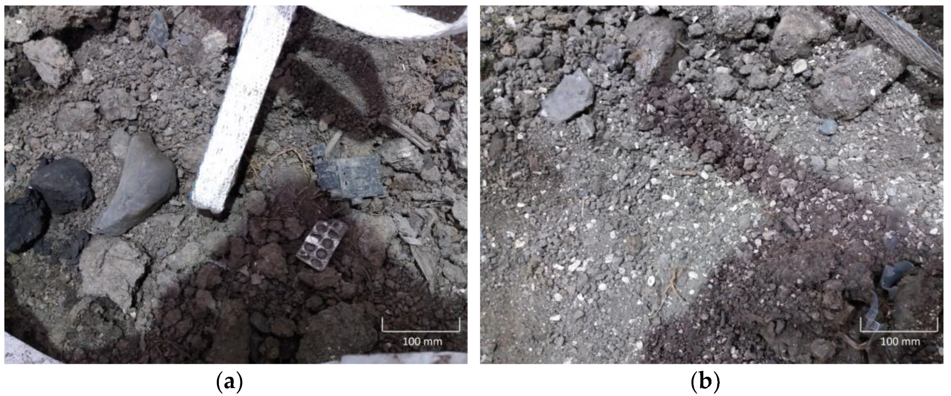
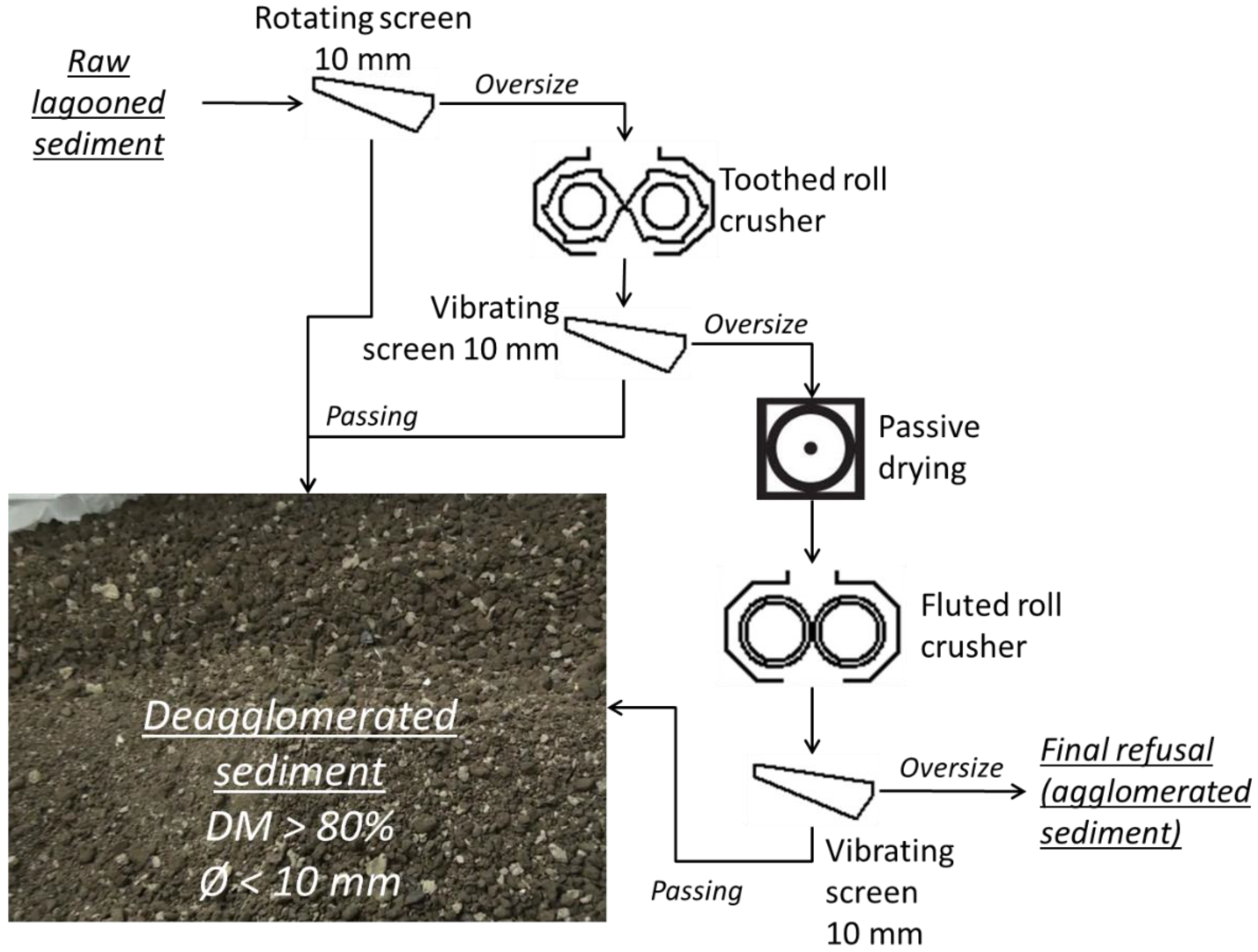
- Concrete used to build a bicycle path: a dry deagglomeration process has been set up and upscaled to supply a large amount of material (13.5 tons). In fact, lagooned sediments can contain large agglomerate blocks (some larger than 0.5 m), which cannot be accommodated inside a concrete mixer. An additional challenge is to deagglomerate the sediment without reducing excessively its moisture content.
- Pozzolanic materials and lightweight clay aggregates, using a wet size classification platform, allowing the separation of the dredged sediments at 63 µm.
2. Materials and Methods
- Dry techniques were used to treat dehydrated river sediments with the aim to deagglomerate them and to incorporate them into a concrete formula, with the final goal being the building of a bicycle path. This concrete is formulated by a project partner and will be the subject of a further publication.
- Wet techniques were used to separate the −63 µm fraction. The final goal was to produce pozzolanic materials [15] or to incorporate the fraction into lightweight clay aggregates [26]; both beneficial uses are thermal techniques. In fact, pozzolanic materials are produced by calcining clay materials at 700–800 °C. Lightweight clay aggregates are formed at temperatures between 1000 and 1100 °C.
2.1. River Sediments and Characterisation
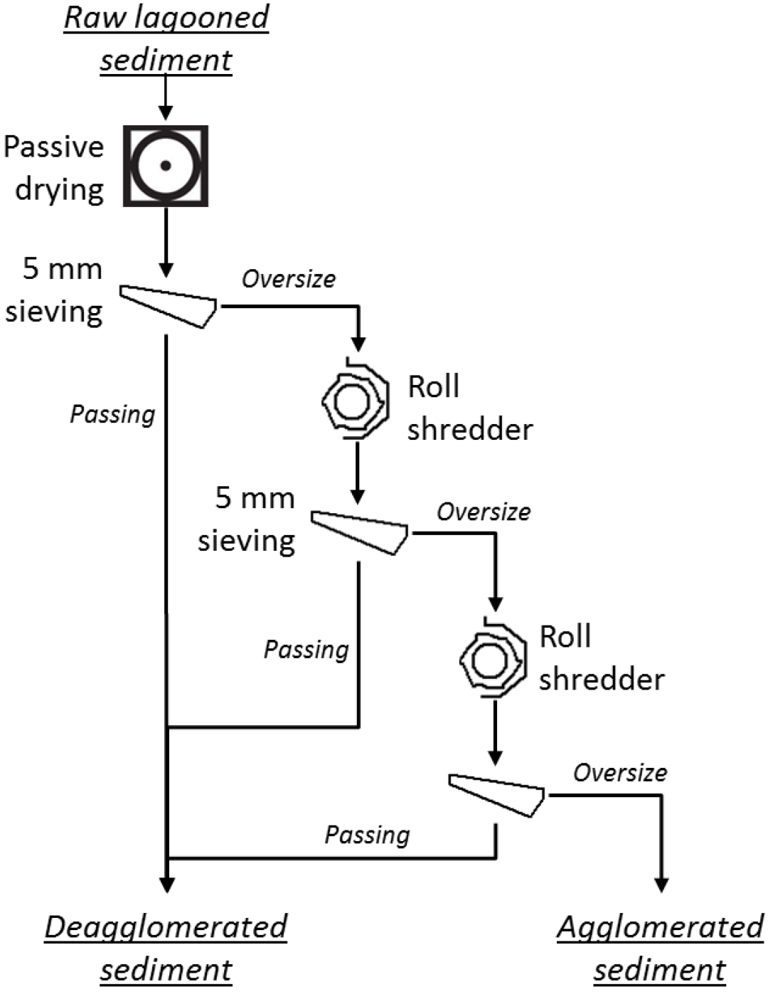
2.2. Dry Techniques Used to Deagglomerate a River Sediment
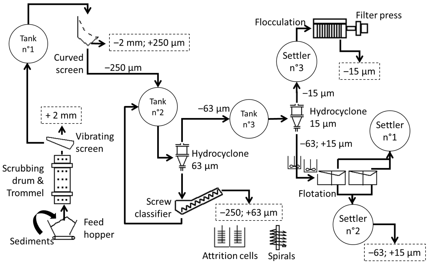
2.3. Wet Techniques Used to Isolate a −63 µm Fraction
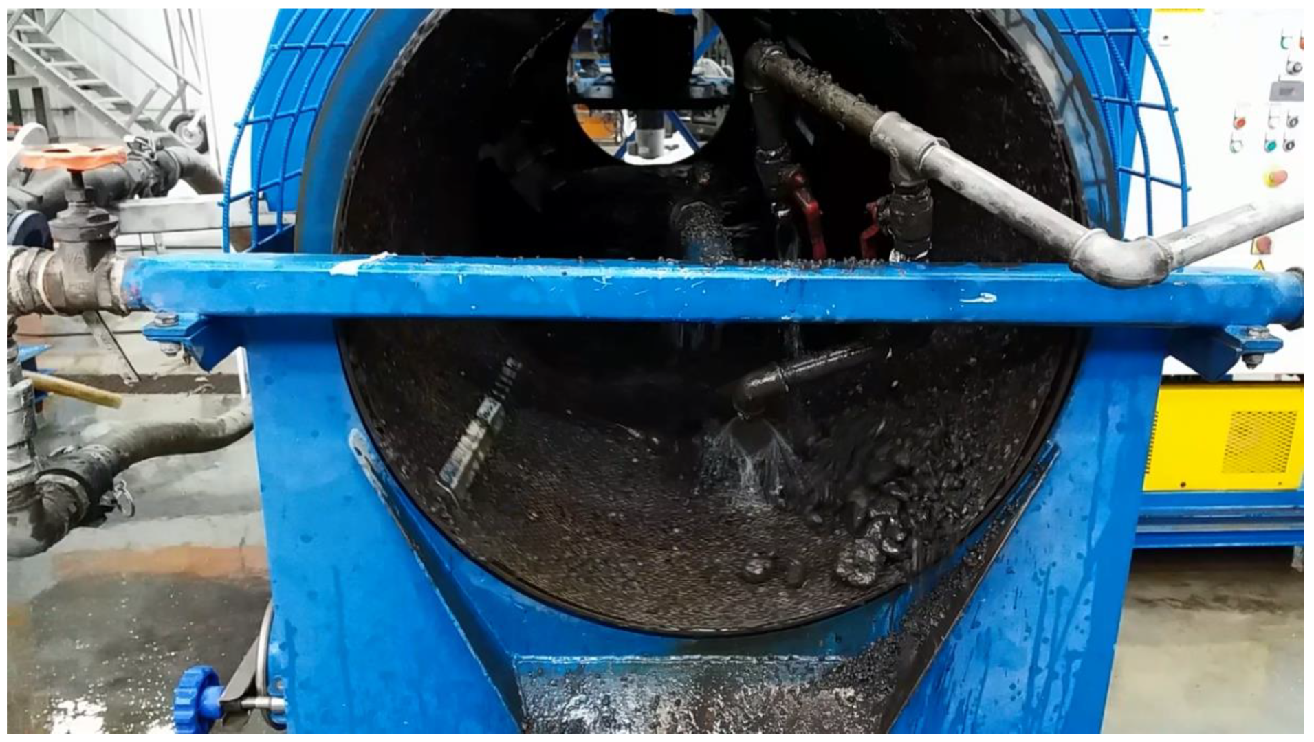
- Wet sieving at 2 mm, using a rotating trommel (working up to 1.2 t/h dry matter on a slurry with a dry matter content of 40–80%) and a vibrating screen (working till 1.2 t/h dry matter on a slurry with a dry matter content of 30–40%);
- Wet sieving at 250 µm on a curved screen (working till 1.2 m3/h on a slurry with a dry matter content of 10–20%);
- A classification at 63 µm using two devices in series: a hydrocyclone (working till 1.2 m3/h on a slurry with a dry matter content of 10–40%) and a screw classifier (working up to 0.8 m3/h on a slurry with a dry matter content of 10–40%). The underflow fraction of the hydrocyclone is refined by the screw classifier. The coarse fraction (+63 µm) is recovered at the discharge of the screw and the overflow fraction of the screw classifier goes back to the hydrocyclone.

3. Results
3.1. Sediment Characterisation
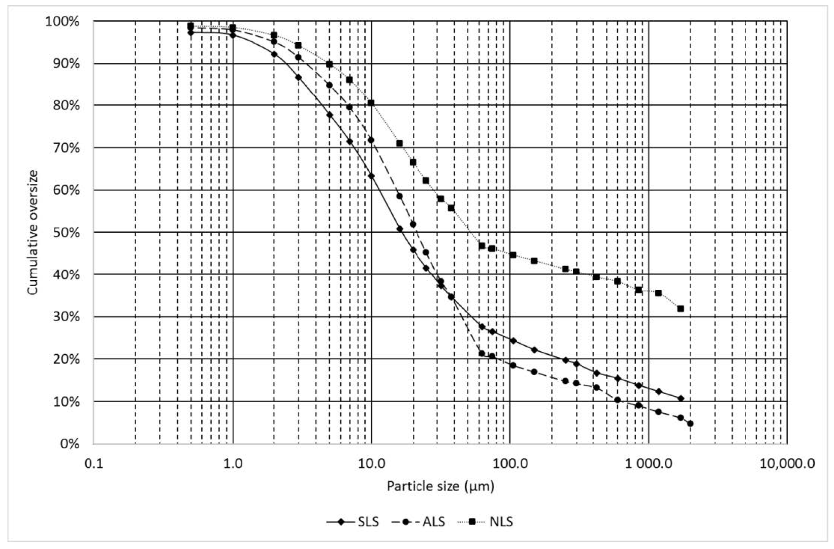
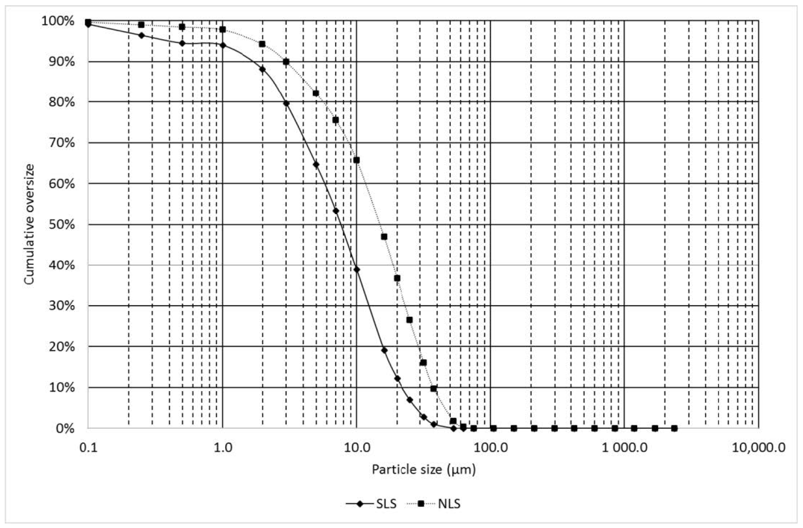
3.1.1. Particle Size Distribution
3.1.2. Chemical Composition
3.1.3. Leaching Behaviour
3.2. Deagglomeration of River Sediments for Incorporation in a Concrete Formulation
- A concrete mixer generally allows material of a maximum 20 mm, namely the maximum size of the mineral granulates. Therefore, any materials, including sediments, must have a particle size below 20 mm. To ensure a good dispersion of the sediment inside the concrete formulation, a much lower maximum size was chosen: first 5 mm and then 10 mm (which is a more common size for industrial screens).
- To increase the contact area between sediment particles and concrete ingredients, the presence of any heterogeneities in the concrete must be avoided.
- To prepare waterway sediment for easier handling by the operators of the concrete plant. It means that the river sediment must be stored in a feed hopper and must be transported to the concrete mixer by conveyor belts.
3.2.1. Preliminary Tests
3.2.2. Preparation of Samples for Laboratory Trials
- Requirement of a further drying step after natural dehydration in the lagoon, with a more advanced technique;
- Sieving at a size of 5 mm, which is less common in dry sieving;
- Presence of a large proportion of final refusal;
- High number of successive steps with similar equipment;
- Low flow rate (0.1 to 0.25 m3/h);
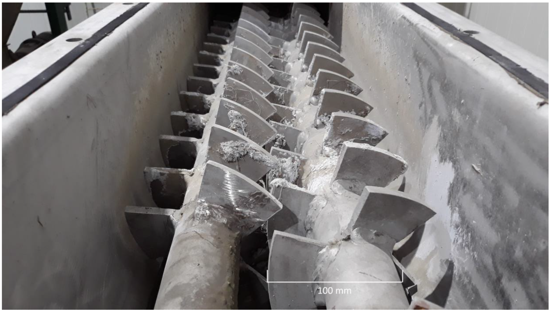
- Potential wear of the single roll shredder, as this equipment is designed for soft materials, such as plastics or biomass, and not for minerals.
3.2.3. Upscaling and Production of a Large Batch of Sediment
3.2.4. Verification of Sediment Quality
3.3. Extraction of the −63 µm Fraction to Produce Pozzolanic Materials and Lightweight Aggregates
3.3.1. Separation of the −63 µm Fraction
3.3.2. Verification of −63 µm Fraction Quality
4. Discussion
5. Conclusions
Author Contributions
Funding
Data Availability Statement
Acknowledgments
Conflicts of Interest
References
- Salomons, W.; Brils, J. Contaminated Sediments in European River Basins. Project Report, EU Project EVK1-CT-2001-20002; TNO: The Hague, The Netherlands, 2004; Available online: http://www.htg-baggergut.de/Downloads/SedNet_booklet_final.pdf (accessed on 16 November 2022).
- Gestion Des Sédiments Retirés Des Voies D’eau Navigables. Available online: http://etat.environnement.wallonie.be/contents/indicatorsheets/DECHETS%209.html (accessed on 16 November 2022).
- Directive 2006/12/Ec of the European Parliament and of the Council of 5 April 2006 on waste (Text with EEA relevance) 27.4.2006 EN Official Journal of the European Union L 114/9. Available online: https://eur-lex.europa.eu/legal-content/EN/ALL/?uri=CELEX%3A32006L0012 (accessed on 16 November 2022).
- European Commission. Circular Economy Action Plan. Available online: https://environment.ec.europa.eu/strategy/circular-economy-action-plan_en (accessed on 16 November 2022).
- Limeira, J.; Agullo, L.; Etxeberria, M. Dredged marine sand in concrete: An experimental section of a harbor pavement. Constr. Build. Mater. 2010, 24, 863–870. [Google Scholar] [CrossRef]
- Zhao, Z.; Benzerzour, M.; Abriak, N.-E.; Damidot, D.; Courard, L.; Wang, D. Use of uncontaminated marine sediments in mortar and concrete by partial substitution of cement. Cem. Concr. Compos. 2018, 93, 155–162. [Google Scholar] [CrossRef]
- Benslafa, F.K.A.; Kerdal, D.; Ameur, M.; Mekerta, B.; Semcha, A. Durability of Mortars Made with Dredged Sediments. Procedia Eng. 2015, 118, 240–250. [Google Scholar] [CrossRef] [Green Version]
- Ozer-Erdogan, P.; Merve Basar, H.; Erden, I.; Tolun, L. Beneficial use of marine dredged materials as a fine aggregate in ready-mixed concrete: Turkey example. Constr. Build. Mater. 2016, 124, 690–704. [Google Scholar] [CrossRef]
- Said, I.; Missaoui, A.; Lafhaj, Z. Reuse of Tunisian marine sediments in paving blocks: Factory scale experiment. J. Clean. Prod. 2015, 102, 66–77. [Google Scholar] [CrossRef]
- Couvidat, J.; Benzaazoua, M.; Chatain, V.; Bouzahzah, H. Environmental evaluation of dredged sediment submitted to a solidification stabilization process using hydraulic binders. Environ. Sci. Pollut. Res. 2016, 23, 17142–17157. [Google Scholar] [CrossRef]
- Beddaa, H.; Ouazi, I.; Ben Fraj, A.; Lavergne, F.; Torrenti, J.-M. Reuse potential of dredged river sediments in concrete: Effect of sediment variability. J. Clean. Prod. 2020, 265, 121665. [Google Scholar] [CrossRef]
- Junakova, N.; Junak, J.; Balintova, M. Reservoir sediment as a secondary raw material in concrete production. Clean Technol. Environ. Policy 2015, 17, 1161–1169. [Google Scholar] [CrossRef]
- Snellings, R.; Cizer, Ö.; Horckmans, L.; Durdziński, P.T.; Dierckx, P.; Nielsen, P.; Van Balen, K.; Vandewalle, L. Properties and pozzolanic reactivity of flash calcined dredging sediments. Appl. Clay Sci. 2016, 129, 35–39. [Google Scholar] [CrossRef]
- Dalton, J.L.; Gardner, K.H.; Seager, T.P.; Weimer, M.L.; Spear, J.C.M.; Magee, B.J. Properties of Portland cement made from contaminated sediments. Resour. Conserv. Recycl. 2004, 41, 227–241. [Google Scholar] [CrossRef]
- Kazemi-Kamyab, H.; Van den Abeele, L.; Henry, M.; Haouche, L.; Snellings, R. Evaluation of calcined dredged sediments as supplementary cementitious materials. In Proceedings of ICSBM 2019 2nd International Conference of Sustainable Building Materials, Eindhoven, The Netherlands, 12–15 August 2019. [Google Scholar]
- Park, J.; Son, Y.; Noh, S.; Bong, T. The suitability evaluation of dredged soil from reservoirs as embankment material. J. Environ. Manag. 2016, 183, 443–452. [Google Scholar] [CrossRef] [PubMed]
- Kamali, S.; Bernard, F.; Abriak, N.E.; Degrugilliers, P. Marine dredged sediments as new materials resource for road construction. Waste Manag. 2008, 28, 919–928. [Google Scholar]
- Zentar, R.; Dubois, V.; Abriak, N.E. Mechanical behaviour and environmental impacts of a test road built with marine dredged sediments. Resour. Conserv. Recycl. 2008, 52, 947–954. [Google Scholar] [CrossRef]
- Beneficial Use of Dredged Sediments in Road Engineering—Methodological Guide. SEDILAB. Available online: https://sednet.org/wp-content/uploads/2019/05/Beneficial-use-of-dredged-sediments-in-road-engineering.pdf (accessed on 16 November 2022).
- Hamer, K.; Karius, V. Brick production with dredged harbour sediments. An industrial-scale experiment. Waste Manag. 2002, 22, 521–530. [Google Scholar] [CrossRef] [PubMed]
- Mezencevova, A.; Yeboah, N.N.; Burns, S.E.; Kahn, L.F.; Kurtis, K.E. Utilization of Savannah Harbor River sediment as the primary raw material in production of fired brick. J. Environ. Manag. 2012, 113, 128–136. [Google Scholar] [CrossRef]
- Cappuyns, V.; Deweirt, V.; Rousseau, S. Dredged sediments as a resource for brick production: Possibilities and barriers from a consumers’ perspective. Waste Manag. 2015, 38, 372–380. [Google Scholar] [CrossRef]
- Wei, Y.L.; Yang, J.C.; Lin, Y.Y.; Chuang, S.Y.; Wang, H.P. Recycling of harbor sediment as lightweight aggregate. Mar. Pollut. Bull. 2008, 57, 867–872. [Google Scholar] [CrossRef]
- Tang, C.W.; Chen, H.J.; Wang, S.Y.; Spaulding, J. Production of synthetic lightweight aggregate using reservoir sediments for concrete and masonry. Cem. Concr. Compos. 2011, 33, 292–300. [Google Scholar] [CrossRef]
- Hung, M.F.; Hwang, C.L. Study of fine sediments for making lightweight aggregate. Waste Manag. Res. 2007, 25, 449–456. [Google Scholar] [CrossRef]
- Peys, A.; Van De Sande, J.; Teck, P.; Snellings, R. A metallurgical approach towards bloating of canal dredging sediments. J. Sustain. Metall. 2021, 7, 1671–1685. [Google Scholar] [CrossRef]
- Kribi, S.K. Décomposition Des Matières Organiques Et Stabilisation Des Métaux Lourds Dans Les Sédiments De Dragage. Ph.D. Thesis, Institut Nationale des Sciences Appliquées de Lyon, Lyon, France, 2005. [Google Scholar]
- Kim, J.O.; Choi, J.; Lee, S.; Chung, J. Evaluation of hydrocyclone and post-treatment technologies for remediation of contaminated dredged sediments. J. Environ. Manag. 2016, 166, 94–102. [Google Scholar] [CrossRef] [PubMed]
- Kim, J.O.; Kim, S.; Chung, J. Recycle and Disposal of Contaminated Dredged Sediments Using the Pilot-Scale Hybrid Process in Dredger. Environ. Prog. Sustain. Energy 2015, 34, 476–484. [Google Scholar] [CrossRef]
- Zhang, C.; Yu, Z.G.; Zeng, G.M.; Jiang, M.; Yang, Z.Z.; Cui, F.; Zhu, M.Y.; Shen, L.G.; Hu, L. Effects of sediment geochemical properties on heavy metal bioavailability. Environ. Int. 2014, 73, 270–281. [Google Scholar] [CrossRef] [PubMed]
- Rulkens, W. Introduction to the treatment of polluted sediments. Rev. Environ. Sci. Bio/Technol. 2005, 4, 213–221. [Google Scholar] [CrossRef]
- Mulligan, C.N.; Yong, R.N.; Gibbs, B.F. An evaluation of technologies for the heavy metal remediation of dredged sediments. J. Hazard. Mater. 2001, 85, 145–163. [Google Scholar] [CrossRef]
- Mouedhen, I.; Coudert, L.; Blais, J.F.; Mercier, G. Prediction of physical separation of metals from soils contaminated with municipal solid waste ashes and metallurgical residues. Waste Manag. 2019, 93, 138–152. [Google Scholar] [CrossRef]
- Lafhaj, Z.; Samara, M.; Agostini, F.; Boucard, L.; Skoczylas, F.; Depelsenaire, G. Polluted river sediments from the North region of France: Treatment with Novosol® process and valorization in clay bricks. Constr. Build. Mater. 2008, 22, 755–762. [Google Scholar] [CrossRef]
- Cauwenberg, P.; Verdonckt, F.; Maes, A. Flotation as a remediation technique for heavily polluted dredged material. 1. A feasibility study. Sci. Total Environ. 1998, 209, 113–119. [Google Scholar] [CrossRef]
- Cauwenberg, P.; Verdonckt, F.; Maes, A. Flotation as a remediation technique for heavily polluted dredged material. 2. Characterisation of flotated fractions. Sci. Total Environ. 1998, 209, 121–131. [Google Scholar] [CrossRef]
- Detzner, H.D.; Schramm, W.; Döring, U.; Bode, W. New technologie of mechanical treatment of dredged material form Hamburg Harbour. Water Sci. Technol. 1998, 37, 337–343. [Google Scholar] [CrossRef]
- Detzner, H.D. The Hamburg Project METHA: Large scale separation, dewatering and reuse of polluted sediments. Eur. Water Pollut. Control 1995, 5, 38–42. [Google Scholar]
- Vandekeybus, J.; Rapisardi, A.; Apitz, S.E. Sustainable Management of Contaminated Dredged Sediments: AMORAS Case Study in the Port of Antwerp. In Proceedings of ConSoil, Salzburg, Austria, 22–24 September 2010. [Google Scholar]
- Van Esbroeck, M.; Dockx, J.; Van De Velde, K.; Pensaert, S.; Pynaert, K.; Horckmans, L. The AMORAS Project: Dewatering and Reuse of the Antwerp Port Sediments. In Proceedings of WODCON XX: The Art of Dredging, Brussels, Belgium, 3–7 June 2013. [Google Scholar]
- VALSE Project. Available online: https://valse.info/ (accessed on 16 November 2022).
- Arrêté du Gouvernement Wallon Relatif à la Gestion Des Matières Enlevées Du Lit Et Des Berges Des Cours Et Plans D’eau Du Fait De Travaux De Dragage Ou De Curage. Available online: http://environnement.wallonie.be/legis/eau/EANNA016.HTM#:~:text=30%20novembre%201995%20%2D%20Arr%C3%AAt%C3%A9%20du,curage%20(M.B.%2013.01.1996) (accessed on 16 November 2022).
- Pereira, F.; Koller, E.; Lucion, C.; Hiver, J.M.; Libert, Y. Integrated and sustainable solutions for the treatment and valorisation of dredging sediment: The “SOLINDUS” project. Proceedings of PIANC 32nd Congress, Liverpool, UK, 10–14 May 2010. [Google Scholar]
- Experimental Pilot Platform for the Treatment of Dredged Sediments. Available online: https://www.dredging.org/resources/ceda-publications-online/beneficial-use-of-sediments-case-studies/63/Experimental%20pilot%20platform%20for%20the%20treatment%20of%20dredged%20sediments (accessed on 16 November 2022).
- Bréquel, H.; Gineys, N.; Urbain, F.; Duchadeau, A.; Couturier, F. Solindus experimental dredged material treatment platform: A versatile solution for sediment treatment and clay flocculation. Proceedings of WODCON XX: The Art of Dredging, Brussels, Belgium, 3–7 June 2013. [Google Scholar]
- Evaluation Des Incidences Des Dragages Des Chenaux De Navigation Et Des Immersions Sur L’état De Conservation Des Sites Natura 2000. GEODE 2008. Available online: https://www.natura2000.fr/sites/default/files/references_bibliographiques/04_guideein2000_complet_dragages.pdf (accessed on 16 November 2022).
- Tsiridis, V.; Samaras, P.; Kungolos, A.; Sakellaropoulos, G.P. Application of Leaching Tests for Toxicity Evaluation of Coal Fly Ash. Environ. Toxicol. 2006, 21, 409–416. [Google Scholar] [CrossRef] [PubMed]
- Wang, F.; Wang, H.; Al-Tabba, A. Leachability and heavy metal speciation of 17-year-old stabilised/solidified contaminated site soils. J. Hazard. Mater. 2014, 278, 144–151. [Google Scholar] [CrossRef] [PubMed]
- Helser, J.; Cappuyns, V. Trace elements leaching from Pb-Zn mine waste (Plombières, Belgium) and environmental implications. J. Geochem. Explor. 2021, 220, 106659. [Google Scholar] [CrossRef]
- Global Cement and Concrete Association. Available online: https://gccassociation.org/concretefuture/cement-concrete-around-the-world/ (accessed on 16 November 2022).


| Sediments | Si | Fe | Al | Ca | K | SO4 | P | Mg | Na | Zn |
|---|---|---|---|---|---|---|---|---|---|---|
| SLS | 20.92 | 6.68 | 6.15 | 2.69 | 1.70 | 1.30 | 0.42 | 0.62 | 0.42 | 0.30 |
| ALS | 22.14 | 3.14 | 4.39 | 7.22 | 1.30 | 0.58 | 0.24 | 0.90 | 0.40 | 0.10 |
| NLS | 17.67 | 3.09 | 4.83 | 8.63 | 1.31 | 2.18 | 0.62 | 0.55 | 0.40 | 0.21 |
| Inorganic Pollutants | Wallonia * | France ** | |||
|---|---|---|---|---|---|
| Maximum Allowable Content | Safety Level | Maximum Allowable Content in Leachate | N1 | N2 | |
| As | 50 | 100 | 0.5 | 25 | 50 |
| Cd | 6 | 30 | 0.1 | 1.2 | 2.4 |
| Co | 25 | 100 | 0.5 | - | - |
| Cr | 200 | 460 | 0.5 | 90 | 180 |
| Cu | 150 | 420 | 2 | 45 | 90 |
| Hg | 1.5 | 15 | 0.02 | 0.4 | 0.8 |
| Ni | 75 | 300 | 0.5 | 37 | 74 |
| Pb | 250 | 1500 | 0.5 | 100 | 200 |
| Zn | 1200 | 2400 | 2 | 276 | 552 |
| F− | 250 | 500 | 20 | - | - |
| CN− | 5 | 25 | 0.1 | - | - |
| Size Fractions | Maximum Allowable Content * | Safety Level * | |||||||
|---|---|---|---|---|---|---|---|---|---|
| Raw | (+1.7 mm) | (−1.7 mm; +250 µm) | (−250; +63 µm) | (−63; +25 µm) | (−25 µm) | ||||
| Mass distribution (%) | - | 10.7 | 9.0 | 7.9 | 14.0 | 58.4 | - | - | |
| Pollutant levels (mg/kgdry matter) | As | 28.4 | 10.8 | 31.1 | 18.3 | 26.1 | 61.8 | 50 | 100 |
| Cd | 55.7 | <10 | 24.1 | 13.7 | 26.4 | 150.8 | 6 | 30 | |
| Co | <25 | <10 | <10 | <10 | <10 | <10 | 25 | 100 | |
| Cr | 176.8 | 121.0 | 144.4 | 103.1 | 154.5 | 295.7 | 200 | 460 | |
| Cu | 190.6 | 41.3 | 107.3 | 86.0 | 118.5 | 305.2 | 150 | 420 | |
| Hg | 0.8 | 0.12 | 0.42 | 0.37 | 1.04 | 1.55 | 1.5 | 15 | |
| Ni | 73.0 | 53.6 | 62.3 | 62.2 | 87.0 | 165.0 | 75 | 300 | |
| Pb | 531.5 | 44.0 | 230.3 | 221.3 | 293.1 | 938.3 | 250 | 1500 | |
| Zn | 3023.0 | 388.8 | 1288.0 | 822.0 | 1350.6 | 5615.1 | 1200 | 2400 | |
| F− | 439.2 | 313.3 | 498.8 | 300.3 | 283.0 | 473.9 | 250 | 500 | |
| CN− | 60.1 | 3.9 | 20.0 | 6.7 | 22.0 | 130.0 | 5 | 25 | |
| Size Fractions | Maximum Allowable Content * | Safety Level * | |||||||
|---|---|---|---|---|---|---|---|---|---|
| Raw | (+2 mm) | (−2 mm; +250 µm) | (−250; +63 µm) | (−63; +25 µm) | (−25 µm) | ||||
| Mass distribution (%) | - | 4.7 | 10.1 | 6.5 | 24.0 | 54.8 | - | - | |
| Pollutant levels (mg/kgdry matter) | As | <10 | <5 | 6.9 | 11.1 | 8.4 | 18.8 | 50 | 100 |
| Cd | 25.3 | 5.2 | 13.6 | 33.5 | 18.4 | 30.1 | 6 | 30 | |
| Co | 11.5 | <5 | 7.6 | 19.0 | 11.4 | 18.2 | 25 | 100 | |
| Cr | 164.9 | 44.3 | 83.2 | 116.0 | 157.7 | 236.8 | 200 | 460 | |
| Cu | 89.0 | 16.0 | 46.3 | 122.6 | 84.6 | 156.5 | 150 | 420 | |
| Hg | 0.9 | 0.0 | 0.2 | 1.1 | 0.5 | 1.1 | 1.5 | 15 | |
| Ni | 41.6 | 24.4 | 38.4 | 63.9 | 46.1 | 58.2 | 75 | 300 | |
| Pb | 197.0 | 17.0 | 59.5 | 144.3 | 110.4 | 365.8 | 250 | 1500 | |
| Zn | 967.0 | 120.2 | 451.2 | 958.6 | 636.4 | 1419.8 | 1200 | 2400 | |
| F− | 569.2 | 867.0 | 233.0 | 218.8 | 231.6 | 205.7 | 250 | 500 | |
| CN− | 2.0 | <1.0 | <1.0 | <1.0 | <1.0 | 4.3 | 5 | 25 | |
| Size Fractions | Maximum Allowable Content * | Safety Level * | |||||||
|---|---|---|---|---|---|---|---|---|---|
| Raw | (+1.7 mm) | (−1.7 mm; +250 µm) | (−250; +63 µm) | (−63; +25 µm) | (−25 µm) | ||||
| Mass distribution (%) | - | 31.8 | 9.5 | 5.5 | 15.3 | 37.9 | - | - | |
| Pollutant levels (mg/kgdry matter) | As | 15.4 | 10.0 | 14.3 | 13.8 | 11.5 | 25.1 | 50 | 100 |
| Cd | <10 | <10 | <10 | <10 | <10 | <10 | 6 | 30 | |
| Co | <10 | <10 | 15.4 | 29.0 | 13.2 | 15.1 | 25 | 100 | |
| Cr | 103.2 | 177.9 | 106.1 | 110.2 | 128.8 | 124.6 | 200 | 460 | |
| Cu | 926.2 | 470.5 | 650.8 | 651.7 | 392.8 | 1042.3 | 150 | 420 | |
| Hg | 1.54 | 0.9 | 1.0 | 0.9 | 1.1 | 2.0 | 1.5 | 15 | |
| Ni | 49.7 | 66.4 | 49.6 | 52.3 | 40.6 | 69.3 | 75 | 300 | |
| Pb | 521.3 | 327.2 | 320.3 | 282.3 | 219.6 | 584.7 | 250 | 1500 | |
| Zn | 2066.2 | 1043.9 | 1401.6 | 1281.5 | 1045.7 | 2418.6 | 1200 | 2400 | |
| F− | 315.5 | 266.7 | 346.7 | 348.3 | 232.5 | 391.9 | 250 | 500 | |
| CN− | 7.3 | 3.1 | 3.3 | 2.5 | 2.2 | 9.9 | 5 | 25 | |
| Pollutants | SLS | ALS | NLS | Maximum Allowable Content * | |
|---|---|---|---|---|---|
| Levels (mg/kgdry matter) | As | <0.5 | <0.5 | <0.5 | 0.5 |
| Cd | 0.95 | <0.04 | <0.04 | 0.1 | |
| Co | <0.5 | <0.5 | <0.5 | 0.5 | |
| Cr | <0.1 | <0.5 | <0.1 | 0.5 | |
| CrVI | <1 | <1 | <1 | 0.1 | |
| Cu | <1 | <1 | <1 | 2 | |
| Hg | <0.001 | <0.001 | <0.001 | 0.02 | |
| Ni | 1.17 | <0.4 | 0.47 | 0.5 | |
| Pb | <0.5 | <0.5 | <0.5 | 0.5 | |
| Zn | 42.06 | <1 | 9.52 | 2 | |
| F− | <10 | 13.70 | <10 | 20 | |
| CN− | <0.01 | 0.01 | <0.1 | 0.1 |
| Fractions | Wet Cake Mass (kg) | |
|---|---|---|
| Wet sediment cakes | 725 | |
| After partial passive drying | 689 | |
| Deagglomerated sediment | After initial sieving | 217 |
| After first crushing and sieving | 314 | |
| After second crushing and sieving | 72 | |
| Total | 603 | |
| Non-deagglomerated sediment | 78 | |
| Fractions | Wet Cake Mass (kg) | |
|---|---|---|
| Wet sediment cakes | 16,612 | |
| Deagglomerated sediment | After initial sieving | 6523 |
| After toothed roll crushing and sieving | 4456 | |
| After partial drying and fluted roll crushing followed by sieving | 2450 | |
| Total | 13,429 | |
| Non-deagglomerated sediment (final oversize) | 30 | |
| Step | Processed Amount in the Step (ton/ton at the Entrance) | Operating Cost (€) |
|---|---|---|
| 1. Sieving | 1.00 | 1.00 |
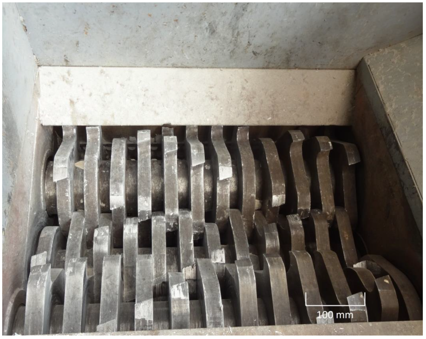
| 2. Toothed roll crushing | 0.57 | 2.84 |
| 3. Sieving | 0.57 | 0.57 |
| 4. Passive drying | 0.26 | 5.19 |
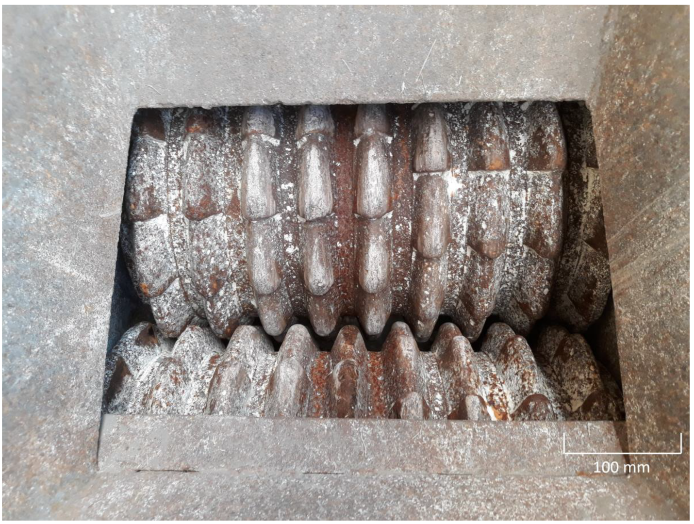
| 5. Fluted roll crushing | 0.17 | 0.86 |
| 6. Sieving | 0.17 | 0.17 |
| Total | 10.62 |
| As | Cd | Co | Cr | Cu | Hg | Ni | Pb | Zn | F− | CN− | |
|---|---|---|---|---|---|---|---|---|---|---|---|
| Characterisation | <10 | 29.8 | 11.5 | 207.4 | 89.0 | 0.9 | 41.6 | 151.8 | 967.0 | 569.2 | 2.0 |
| Deagglomerated sediment for laboratory trials | 14.4 | 22.7 | 14.0 | 99.3 | 93.0 | 1.0 | 53.4 | 232.7 | 1080.0 | 430.6 | n.a. |
| Large batch of deagglomerated sediment | 13.5 | 25.7 | 14.9 | 176.1 | 109.0 | 0.8 | 47.6 | 217.1 | 1014.5 | 160.6 | n.a. |
| Maximum allowable content * | 50 | 6 | 25 | 200 | 150 | 1.5 | 75 | 250 | 1200 | 250 | 5 |
| Safety limit * | 100 | 30 | 100 | 460 | 420 | 15 | 300 | 1500 | 2400 | 500 | 25 |
| −63 µm Fraction | SiO2 | Al2O3 | Fe2O3 | CaO | MgO | K2O | Na2O | SO3 | P2O5 |
|---|---|---|---|---|---|---|---|---|---|
| SLS | 40.8 | 13.9 | 10.0 | 2.6 | 1.1 | 2.1 | 0.5 | 1.0 | 1.1 |
| NLS | 32.2 | 8.2 | 4.3 | 10.8 | 0.9 | 1.6 | 1.9 | 4.0 | 1.4 |
| Reference | Applied Pre-Treatment. |
|---|---|
| [6] | 40 °C drying and grinding below 80 µm. |
| [7] | Washing (desalination). |
| [8] | 3 mm dry sieving and 105°C drying.3 mm dry sieving, washing (desalination), dewatering by filter-press, 105°C drying and 63 µm dry sieving. |
| [9] | 60°C drying, hand and jaw crushing, and 8 and 3 mm dry sieving. |
| [10] | 20 mm dry sieving and weathering.45 °C drying before use. |
| [11] | Natural drying, wet sieving at 80 µm and drying of the refusal at 80 °C. |
| [12] | Natural drying. |
Disclaimer/Publisher’s Note: The statements, opinions and data contained in all publications are solely those of the individual author(s) and contributor(s) and not of MDPI and/or the editor(s). MDPI and/or the editor(s) disclaim responsibility for any injury to people or property resulting from any ideas, methods, instructions or products referred to in the content. |
© 2023 by the authors. Licensee MDPI, Basel, Switzerland. This article is an open access article distributed under the terms and conditions of the Creative Commons Attribution (CC BY) license (https://creativecommons.org/licenses/by/4.0/).
Share and Cite
Henry, M.; Haouche, L.; Lemière, B. Mineral Processing Techniques Dedicated to the Recycling of River Sediments to Produce Raw Materials for Construction Sector. Mining 2023, 3, 54-76. https://doi.org/10.3390/mining3010003
Henry M, Haouche L, Lemière B. Mineral Processing Techniques Dedicated to the Recycling of River Sediments to Produce Raw Materials for Construction Sector. Mining. 2023; 3(1):54-76. https://doi.org/10.3390/mining3010003
Chicago/Turabian StyleHenry, Mathieu, Laurence Haouche, and Bruno Lemière. 2023. "Mineral Processing Techniques Dedicated to the Recycling of River Sediments to Produce Raw Materials for Construction Sector" Mining 3, no. 1: 54-76. https://doi.org/10.3390/mining3010003