Article

Development and Characterization of Novel Anisotropic Skin Graft Simulants

1
Centre for Biomedical Engineering, Indian Institute of Technology (IIT), Delhi 110016, India
2
Department of Biomedical Engineering, All India Institute of Medical Sciences (AIIMS), Delhi 110029, India
*
Author to whom correspondence should be addressed.
Dermato 2023, 3(2), 114-130; https://doi.org/10.3390/dermato3020010
Submission received: 9 December 2022 / Revised: 10 April 2023 / Accepted: 8 May 2023 / Published: 10 May 2023

Abstract

:
Split-thickness skin grafting is a well-known procedure for the treatment of small- and medium-sized burns. However, its effectiveness has been reported to be limited in the case of large and severe burns due to much lower real expansion offered by the grafts than the claimed expansion by graft mesh manufacturers. Recent computational studies have indicated that the collagen fiber orientation within the skin layers have a significant effect on the skin graft expansion. In this study, biofidelic anisotropic synthetic skin with one and two layers and all possible fiber orientations were developed, and incision patterns used in traditional graft meshing techniques were projected to fabricate novel synthetic skin grafts with a theoretical meshing ratio of 3:1. A biaxial tensile testing device was designed to simulate skin graft stretching in clinical settings, and a wide range of synthetic skin graft variants were mechanically tested. The measured quantities included induced nonlinear stress–strain, void area, and meshing ratio. In addition, the stress–strain responses were characterized using nonlinear hyperelastic models. The key observations include the generation of higher induced stresses in two-layer grafts. In the one-layer graft models, a 15° fiber orientation produced the highest expansion at a minimal stress value of 0.21 MPa. In the two-layer graft models, the 45°–15° fiber orientation generated the maximum expansion with minimum stress. A range of such findings were analyzed to determine the graft orientations that may allow enhanced expansion without generating much stress. This information would be indispensable not only for understanding the expansion potential of skin grafts, but also for further research and the development of skin grafts with enhanced expansion for severe burn injury treatment.

1. Introduction

Skin grafting is widely used as a standard surgical method for reconstructing soft tissues [1,2,3]. In the case of extensive defects or restricted donor site availability, such as in the case of severe burns, skin grafts may be stretched beyond their initial geometry [1,2,3,4]. Consequently, a smaller graft may be applied to repair larger damage [5]. Tissue expansion and skin graft meshing are the two methods generally performed for skin enlargement [6]. The first procedure involves overstretching the skin through gradual mechanical distention, typically in the form of a surgically implanted, gradually expanding silicone implant placed under the skin [7,8]. This process is gradual and typically takes several weeks, but it allows the expansion of skin without a significant reduction in its thickness [9,10]. In the second procedure, meshing requires the insertion of a pattern of several uniform short parallel incisions into a sheet of graft, typically using a specific roller instrument [11]. The incisions open when perpendicular stretching is applied, producing a regular concertina pattern [2].
Mesh grafts are a type of skin graft in which the skin is expanded by cutting it into a mesh-like pattern [12]. The meshing technique is used to increase the surface area of the skin graft, allowing it to cover larger wounds [12,13]. An autologous skin graft is a surgical procedure that involves taking a piece of skin from one part of a person’s body (the donor site) and transplanting it to another area of the same person’s body (the recipient site) to cover a wound or injury [14,15]. The advantage of using a person’s own skin for grafting is that the risk of rejection is very low, since the body recognizes the transplanted tissue as its own. In the literature, autologous skin grafting is described as the optimal method of treating extensive and deep burns [16,17]. However, when the vascularization of the wound is not sufficient to accept a free split-thickness skin transplant, allogeneic skin grafts are an excellent choice for wound healing [18]. The MEEK technique was an earlier method used to increase the surface area of skin grafts, which involved cutting the graft into small squares and reassembling them to create a mesh-like pattern [19]. However, this technique has been largely replaced by the faster and simpler mesh technique, which involves using a specialized tool to create the mesh pattern in the skin graft. The MEEK technique had several drawbacks. The process was time-consuming and required specialized equipment and skilled surgeons to perform. Additionally, the small squares of skin were difficult to handle and could result in a graft that was less aesthetically pleasing than those produced by other skin grafting techniques [19,20,21].
In 1964, Tanner et al. introduced the technique of meshed skin grafting [22]. Time and ingenuity have permitted improvements and refinements to the procedure; different expansion ratios can be obtained by utilizing longer incisions, and the technique has become more convenient as a result of technologies such as electrical devices. The meshing ratio is one of the key measures of skin graft expansion, expressed as the ratio of the area expansion of the skin and the initial area [1,2,23]. Theoretical meshing ratios of 1 to 1, 2 to 1, and 3 to 1 are commonly used to estimate skin graft expansion [22,24,25]. The selection of a suitable skin graft mesher is of the utmost importance to generate high expansion [13,24,26,27].
Skin expanders, also known as tissue expanders, are medical devices that are used to expand the skin and underlying tissue in order to prepare the area for reconstructive surgery [28]. They are often used in cases where there is not enough healthy tissue to cover a wound or in cases where the skin needs to be stretched to cover a larger area [29]. A tissue expander is a silicone balloon that is inserted under the skin and gradually inflated with a saline solution over a period of weeks or months [30,31]. As the balloon expands, it stretches the skin and underlying tissue, causing new skin cells to grow and creating excess skin that can be used for reconstruction. One type of reconstructive surgery that can be performed using tissue expanders is called a rotatory flap. A rotatory flap is a surgical procedure in which a section of skin is rotated from one area of the body to another to cover a wound. In order to perform a rotatory flap, the skin in the area where the flap will be rotated from needs to be stretched to allow for the movement of the skin [32,33].
The mesh skin graft expander (Padgett Instruments, Kansas City, MO, USA), made of stainless-steel blades and roller, is coated with Teflon (non-reactive, nonstick surface). This roller produces a honeycomb-like structure on the donor skin [22]. The Xpanderm (Linvatec Corp., Largo, FL, USA) also transfers a honeycomb pattern onto the donor skin, allowing expansion up to three times the initial size of the donor skin [6]. Roller meshing devices with cutting blades at one side or a washing-machine wringer-type instrument are employed to cut the graft at a specific length [34] with interrupted blades and flat derma carriers. One of the earliest meshers (1964) employed a Tanner–Vandeput model, where the generated graft mechanical properties after healing was complete were the same as the donor skin properties measured before grafting [22]. The mesh-dermatome I (Zimmer Co., Dover, OH, USA) skin graft mesher is one of the most popular skin grafting devices. The mechanical characteristics of this device include the length of the cut (i.e., L = 0.3 inch), the length of the gap between the cuts (i.e., g = 0.03 inch), the width between the blades (i.e., d = 0.05 inch), the size of the roller (4 inches), and a 12-inch dermacarrier. The estimated theoretical expansion was 2.35:1, and the maximum real expansion claimed was 3:1 [13,22]. The Zimmer skin graft mesher (Zimmer Co. Dover, OH, USA) is another commonly used mesher with integrated cutters suitable for expansion ratios of 1.5:1, 2:1, and 3:1, respectively. The mechanical characteristics of this device are the length of cut (i.e., L = 0.18 to 0.3 inch), the length of the gap between the cuts (i.e., g = 0.03 inch), and the width between the blades (i.e., d = 0.05 inch) [5,22].
Capek et al. [1] studied the influence of langer lines and orientation on skin grafting. They observed that as the langer lines changed from perpendicular to parallel, the maximum meshing ratio decreased by 20%. Pripotnev et al. [35] conducted an experimental study on 210 burn patients. In all the patients, a burn area of more than 20% of the total body surface was considered. In their study, the authors utilized mesh and expandable skin grafts to reconstruct larger wounds, and a maximum meshing ratio of 3 was considered to be the best choice to recover the burn area. Kan et al. [25] studied skin grafting through experiments on 51 burn patients with different meshing ratios of 1.5:1, 3:1, and 6:1. They observed that none of the experimentally measured meshing ratios reached the claimed meshing ratio, and the maximum meshing ratio value was 3.38 for 6:1 skin grafts. Lyons et al. [36] investigated the difference in meshing ratios with different meshes. They studied the expansion ratios of 1:1, 1.5:1, 2:1, 3:1, and 4:1, and compared them with the clinically achieved meshing ratios. In their study, the 4:1 meshing device showed a maximum difference of 28.3%, and none of the meshers achieved the claimed meshing ratios, except one with a 1:1 ratio. Gupta et al. [2] studied the effect of the slit size and spacing in the skin grafts using computational and experimental methods. The achieved meshing ratios were reported to be much lower than the claimed meshing ratios. Henderson et al. [37] conducted a comprehensive comparison between the declared and actual expansion ratios. While a significant difference (up to 46%) was observed, no specific explanation was provided. Therefore, it is imperative to study skin graft properties and expansion potential in detail [7,8]. Recently, Makode et al. [38] studied the anisotropy of skin through the development of biofidelic synthetic skin.
The purpose of this work is to characterize the actual expansion offered by skin grafts with different claimed meshing ratios (e.g., 1:3) through experiments on biofidelic and anisotropic synthetic skin. This considers the previous literature reporting on low expansion offered by traditional skin grafts. Specifically, the orientation of the Langar lines induce anisotropy to the skin, leading to varying material properties observed across body locations. To date, the effect of Langar line orientations on skin grafts’ expansion properties have not been studied either through experiments or computationally. The current work attempts to understand the effect of all possible Langar line orientations on skin graft expansion.

2. Materials and Methods

Synthetic skin, also known as artificial skin, refers to a material that mimics the properties of human skin [39]. The development of synthetic skin has been driven by the need for skin replacement in various medical applications, including burn treatment, wound healing, and plastic surgery [39,40]. Synthetic skin can be classified into two main categories: biological and non-biological. Biological synthetic skin is typically made from animal or human donor tissues, which are processed to remove the cells and leave behind a collagen scaffold that can support the growth of new cells [41,42]. Non-biological synthetic skin, on the other hand, is made from synthetic materials, such as polymers, that are designed to mimic the structure and properties of human skin [43]. One of the key challenges in developing synthetic skin is replicating the complex structure of human skin, which consists of several layers with different functions. To date, several researchers have designed and developed isotropic synthetic skin [44,45,46]. In this work, we have developed anisotropic single- and multilayer synthetic skin for studying realistic expansion in skin grafts.
Figure 1 shows the schematic representation of the synthetic skin graft technology development.
  • Material composition: A suitable material composition was selected for the matrix and fibers to develop the anisotropic synthetic skin.
  • Mold development: Different molds were designed for different fiber orientations and for hosting the material compositions for the fiber and matrix. The designs were printed using a high-definition 3D printer.
  • Fiber fabrication: The material for the fibers was first poured into the channels in the mold, and then left to set for 30 min.
  • Matrix fabrication: The material for the matrix was poured on top of the partially set fibers and filled the entire mold after 30 min, and was left to set for 8 h.
  • Sample removal: After 8 h, the fibers and matrix were integrated, and the synthetic skin sample could be removed from the mold.
  • Synthetic skin graft development: Stencils or dies with a slit cut pattern as per the meshing ratios (e.g., 1:3) were 3D printed and a cutting knife could be used to cut the slits, or they could be cut directly using a 3D cutter.
  • Mechanical testing: Mechanical testing can be conducted on a biaxial testing device at a strain rate of 24 mm/min, and can be compared to our test results or with the literature to ensure consistent skin graft mimicking [38,47,48].

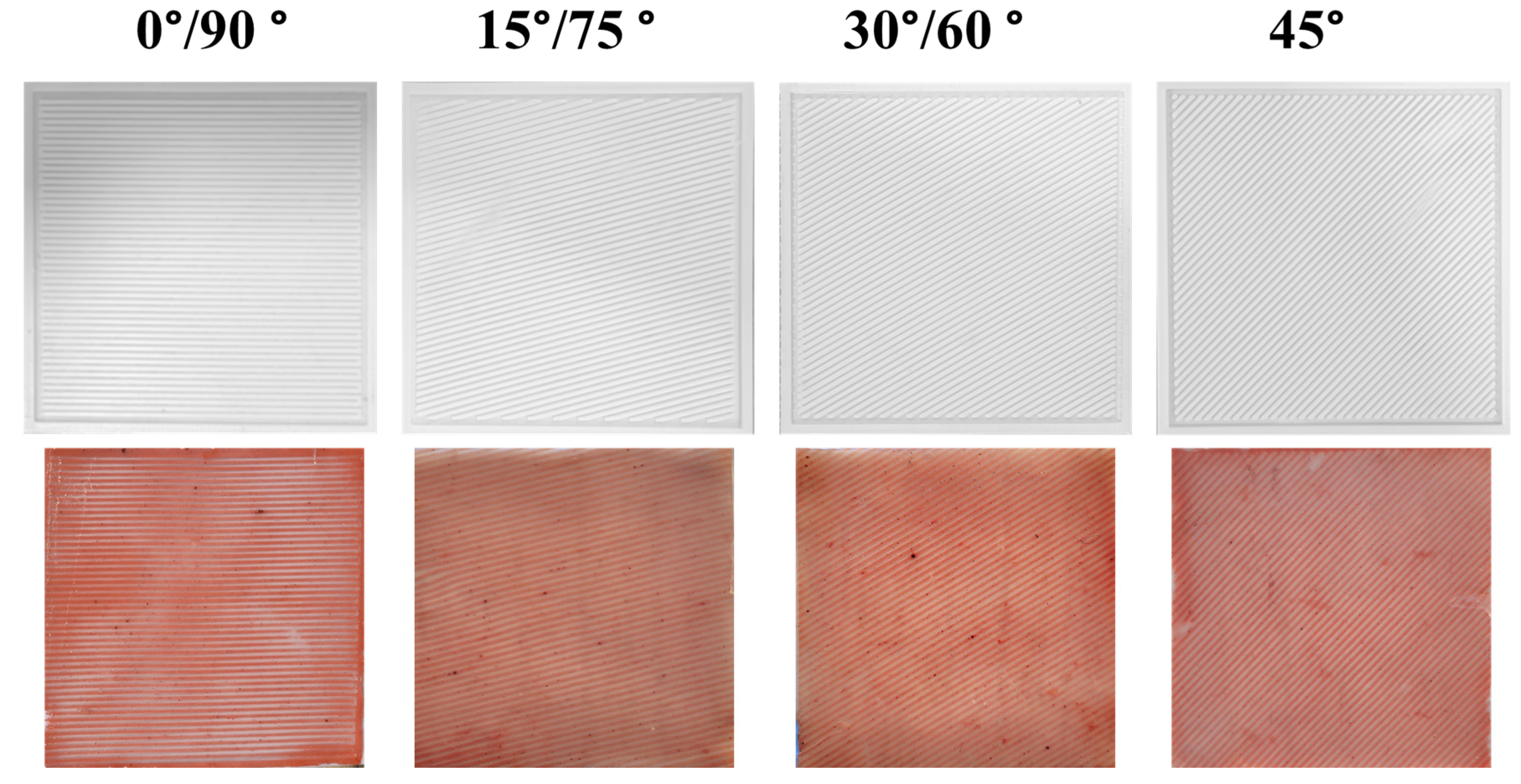
2.1. Design and Development of One-Layer Synthetic Skin

One-layer synthetic skin samples with various fiber orientations were created using two different methods [38,49]. The first method involved pouring the fiber-mimicking polymer (30 A shore hardness) into a mold with 1 mm wide openings for the fibers and curing it for 90 min. After 1 h, the polymer was removed from the mold and placed upside down in a hollow 2-mm-thick square mold. The 10 A shore hardness matrix polymer was added to the cured mixture and cured for 15 min. Before removing the final soft-composite mixture, the second mold was utilized for pouring and curing the matrix polymer (Figure 2). The ASTM D2240 Shore (Durometer) hardness scale was used to classify the anisotropic synthetic skin materials [50]. A two-part 10 A shore hardness silicone matrix was developed. The PLA mold was designed in SolidWorks 2020 (Dassault Systemes, Vélizy-Villacoublay, France) and printed on a 3D-Creality Ender 3 (Shenzhen, China). Figure 2 displays the fiber-oriented molds. Five synthetic skin samples were fabricated to test each fiber orientation. Every sample was 100 mm × 100 mm × 2 mm, with 1 mm fiber spacing. The 0° specimens had fiber lengths of 100mm, while the 45° specimens had fiber lengths of 141.4 mm. The estimated fiber lengths for the different orientations (15°, 30°, 60°, 75°) ranged from 2.5 mm to 141.4 mm. The fiber spacing and dimensions were chosen to keep the fiber volume fraction about the same for all the test specimen orientations. Biaxial investigation renders the 0°, 15°, and 30° synthetic skin results the same as 90°, 75°, and 30°, respectively.

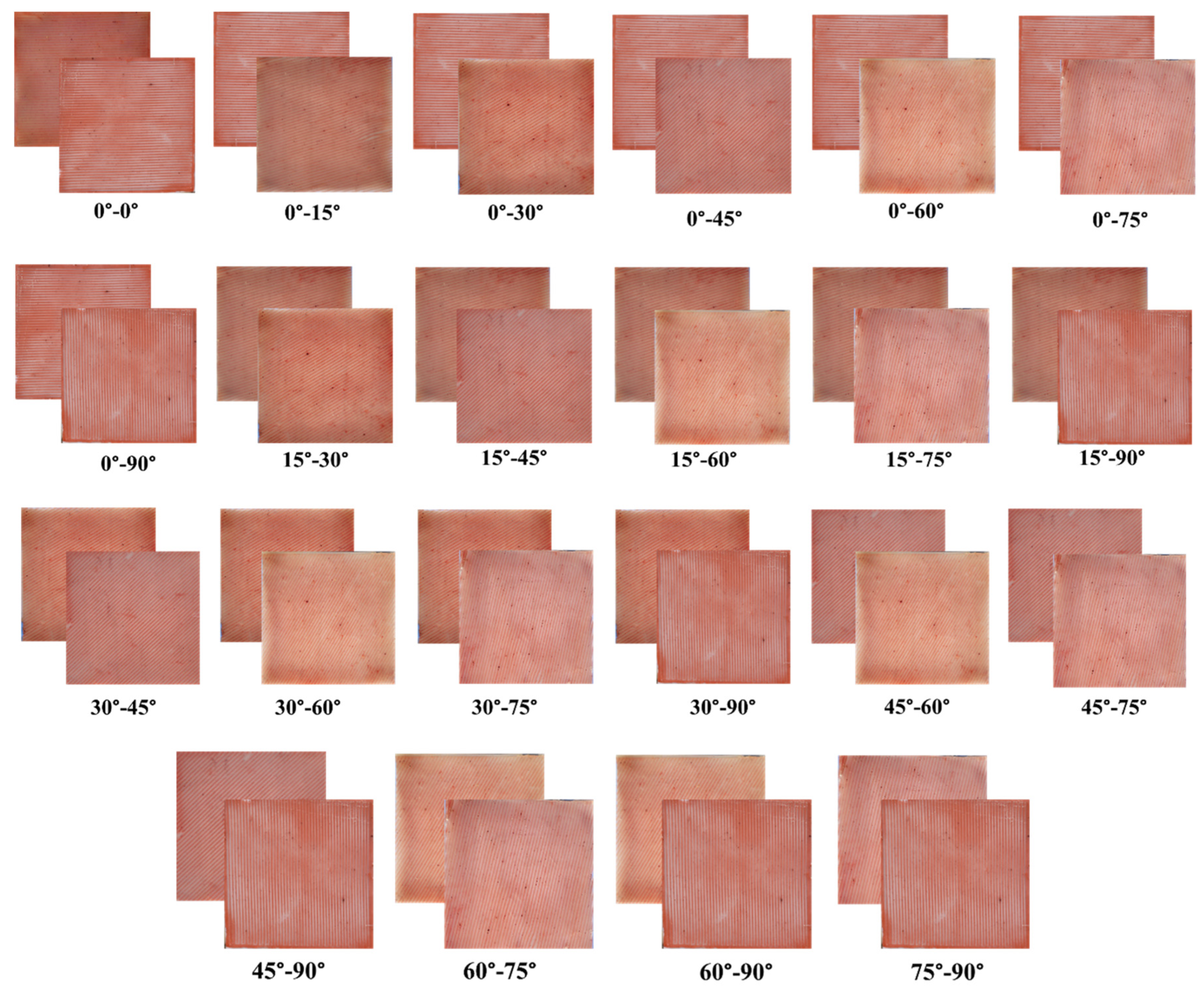
2.2. Development of Two-Layer Synthetic Skin

Figure 3 shows all the different combinations of two-layer synthetic skin (i.e., 0°–0°, 0°–15°, 0°–30°, 0°–45°, 0°–60°, 0°–75°, 0°–90°, 15°–30°, 15°–45°, 15°–60°, 15°–75°, 15°–90°, 30°–45°, 30°–60°, 30°–75°, 30°–90°, 45°–60°, 45°–75°, 45°–90°, 60°–75°, 60°–90°, and 75°–90°). The outer dimensions of the two-layer synthetic skin that were created were 100 mm × 100 mm × 3.5 mm. The layer-wise fiber orientations of the simulants varied, as well. The synthetic skin was produced using fibers with a uniform area of 1 mm × 1 mm, which were arranged in two layers with a matrix of 0.5 mm in between, as well as on the top and bottom of the layer. In order to fabricate these stimulants, three distinct 3D-printed molds were utilized. Two of these molds included fiber grooves that were oriented in a variety of directions, while the third mold was hollow and graded in order to assemble the synthetic skin in a layer-by-layer manner. The preparation of the layers began with a bottoms-up method that consisted of a 0.5 mm thicker matrix, which was then followed by one-layer simulants of the first orientation and a thickness of 1 mm, a 0.5 mm thicker matrix, one-layer simulants of the second orientation with a thickness of 1 mm, and a 0.5 mm thicker matrix. It is essential to note that the curing period was managed in such a manner that all of the layers would have strong linkage, and the matrix would be spread evenly through the whole structure [38,51,52,53].
Two different methods were used to create the one-layer synthetic skin with varying fiber orientations. The fibers were created by pouring the fiber-mimicking polymer (i.e., with 30 A shore hardness) into a mold with 1 mm broad slots for fibers up to 1 mm thickness, and curing the mixture for 90 min. The fibers were created by pouring the fiber-mimicking polymer (i.e., with 30A shore hardness) into a mold with 1mm broad slots for fibers up to 1 mm thickness, and curing the mixture for 90 min. The portion was removed from the mold after 1 h and placed upside down in a hollow square mold with a slightly bigger area and a thickness of 2 mm. The matrix representative polymer (i.e., 15 A shore hardness) was poured on top of the cured mixture and allowed to cure for 45 min. This second mold was used to pour and cure the matrix representative polymer before the final soft-composite mixture was removed. Five different synthetic skin specimens were created so that each possible fiber orientation could be simulated. Every sample was created to have uniform dimensions of 100 mm × 100 mm × 2 mm, with the fibers measuring 1 mm × 1 mm in area, varying in length, and spaced 1 mm apart. The different orientations were the cause of the various fiber lengths. The specimens at 0° had complete fiber lengths of 100 millimetres, whereas the specimens at 45° had fiber lengths of 141.4 mm. The estimated fiber lengths of the specimens that had any of the other possible orientations (15°, 30°, 60°, or 75°) ranged anywhere from 2.5 mm to 141.4 mm. The goal of selecting this particular fiber spacing and dimensions was to maintain the fiber volume fraction at nearly the same level for all of the different orientations of the test specimens. It is important to note that the results of the 0° synthetic skin will be same as the 90° sample because of the biaxial study. Similarly, the results for 15° and 75° and 30° and 60° are also same for this biaxial testing (Figure 3).

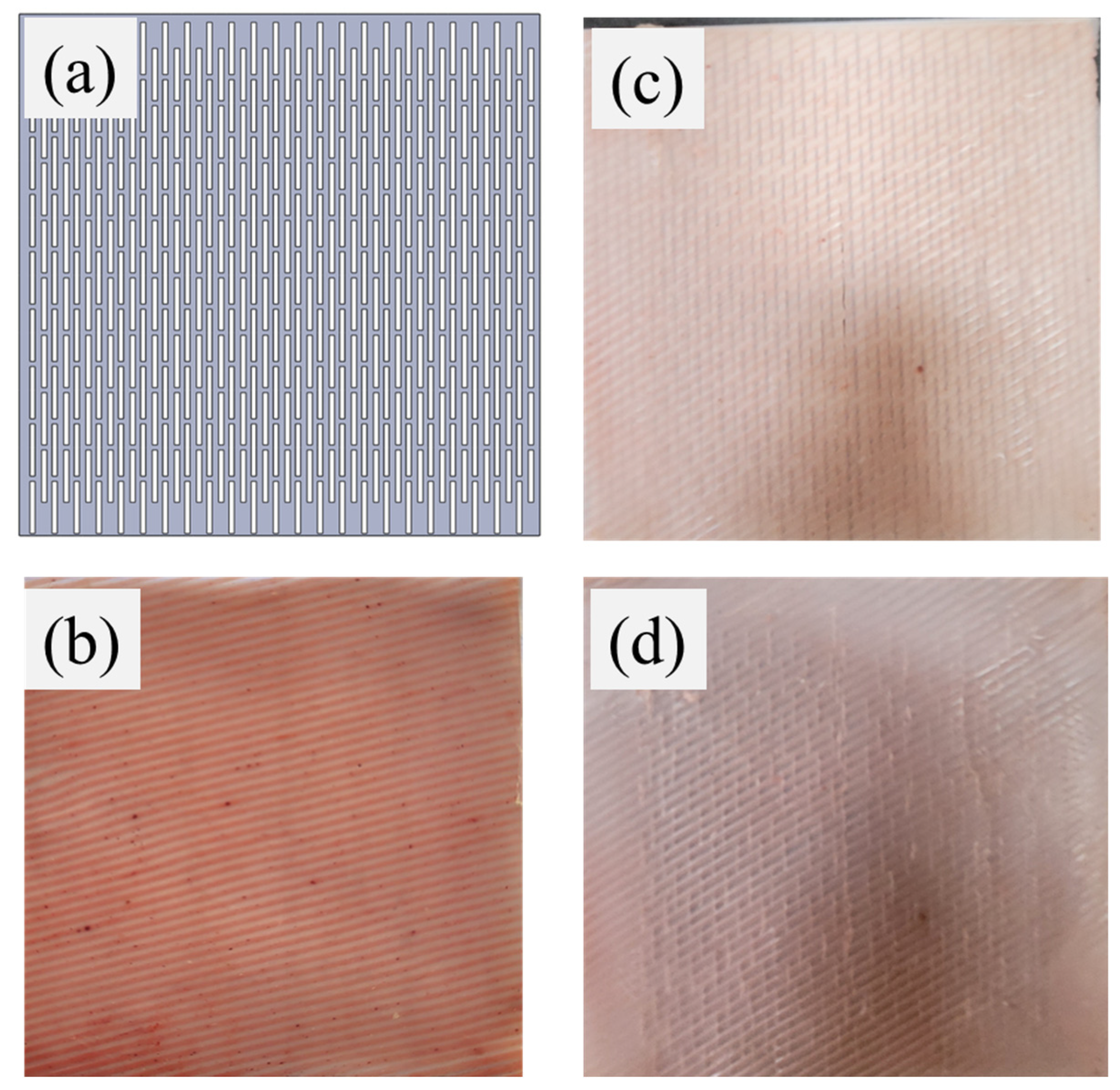
2.3. Development of Anisotropic Synthetic Skin Grafts

An additive manufacturing technique was employed to develop the anisotropic skin grafts [54]. Based upon the prior studies and a detailed literature review on skin graft meshers, the length, spacing, and gap between two consecutive slits were calculated to develop a 3:1 skin graft. In order to create the incisions on anisotropic synthetic skin, a replica of the skin grafts was printed using a 3D-printer. This 3D print was placed on the synthetic skin, and a surgical blade was used to develop the skin grafts. Each synthetic skin sample was precisely converted into the skin grafts and tested further. At the same time, to develop the skin grafts, three protocols were followed. First, the size of the skin sample and the size of the 3D-printed part were made the same. Second, the proper place to hold the skin and 3D-printed part were determined. Third, each line was aligned and cut with the help of surgical blades. Figure 4 shows the schematic of the skin graft development. For developing the anisotropic skin grafts, four consecutive steps were followed. Firstly, we designed and developed 3D-printed slits with a length of 10 mm, 0.5 mm slit thickness, and a 2 mm gap between two repeated slits based upon the 3:1 mesher dimension. Secondly, we placed the anisotropic skin onto the 3D-printed slits (as shown in Figure 4b,c). Thirdly, every slit was cut with proper alignment using surgical blades. As shown in Figure 4d, the anisotropic skin graft was prepared for further analysis.
The time taken to design and develop the synthetic skin was approximately 10.5 h. It is divided into three parts. First, the printing of different molds was carried out (roughly 1–2 h for each mold); second, fabrication of the anisotropic synthetic skin was executed (approximately 6–8 h); and third, we developed the synthetic skin grafts through cutting (approximately 30 min for each pattern). The total cost per sample was approx. INR 500 INR (i.e., approx. USD 6), considering the polymer material and 3D printing costs. Additionally, it should be mentioned that the material cannot be restored to its original form.

2.4. Material Characterization

Figure 5 shows the schematic representation of the biaxial testing setup and attachment of the synthetic skin graft samples. Equibiaxial loading was applied with a constant strain rate of 24 mm/min up to 50% strain. Two load cells with a maximum measurement capacity of 40 kg were employed to estimate the forces applied to the specimen [54]. The displacements were calculated using the lead screw pitch and number of rotations. It should also be mentioned that the slit patterns in the synthetic skin grafts did not extend all the way up to the edge and had 2 cm margins. However, as the margins on each side of the sample were linked to (i.e., within) the clamps, they did not affect the overall results.
The important role of cell proliferation is dependent on the void area and meshing ratio. The void area, which refers to an area that is empty or has nothing in it, is particularly significant in the context of skin grafting and is defined as the area between the unit cells of the graft. The void area was calculated using the open-source ImageJ image processing and analysis software. The steps to calculate the void included opening the ImageJ software (NIH, USA) and inserting the graft image for area estimation. This was followed by calibration of the image to ensure that the maximum lengths were correct. The region of interest (i.e., the void region) was then selected using different toolbars, such as rectangle, freehand, etc. To calculate the area of the void region, a well-defined ImageJ tool was used. It is important to note that the area value is displayed in square pixels or square units, depending on the image calibration. The product of this value and a calibration multiplier will yield the total void area.
Soft tissue and polymer-based materials have a non-linear stress–strain profile. Skin grafts have been observed to have less stress compared to skin at high strain [55]. Hyperelastic constitutive material models (e.g., Fung, Yeoh, Humphrey) can be used to characterize the non-linear mechanical behavior of synthetic skin grafts. In this study, Yeoh, Mooney–Rivlin, and the neo-Hookean hyperelastic curve fit model were used to calculate the constant coefficients ( c 1 , c 2 , and c 3 ) [56,57,58,59]. Non-linear hyperelastic curves work on the strain energy density function ( Ѱ ) , which is based on the material type. In an isotropic hyperelastic model, the strain-energy function is dependent on the principal stretches (λ1, λ2, and λ3) or the Cauchy–Green tensor invariants (I1, I2, and I3, which are also functions of the principal stretches), as shown in Equations (1)–(4) [60,61,62,63].
Ѱ i s o t r o p i c = Ѱ ( I 1 , I 2 , I 3 )
I 1 = i = 1 3 λ i 2
I 2 = i , j = 1 3 λ i 2 λ j 2 i j
I 3 = i = 1 3 λ i 2
The strain energy and stress function of the hyperelastic models are shown in Equations (5)–(11):
Ѱ Y e o h = c 1 ( I 1 3 ) 1 + c 2 ( I 1 3 ) 2 + c 3 ( I 1 3 ) 3
Ѱ M o o n e y R i v l i n = c 1 ( I 1 3 ) + c 2 ( I 2 3 )
Ѱ N e o H o o k e a n = c 1 ( I 1 3 )
σ 1 = λ 1 Ψ λ 1 λ 3 Ψ λ 3
σ Y e o h = 2 ( λ 2 1 λ ) ( c 1 + 2 c 2 ( I 1 3 ) + 3 c 3 I 1 3 2 )
σ M o o n e y R i v l i n = 2 ( λ 2 1 λ ) ( c 1 + c 2 1 λ )
σ N e o H o o k e a n = 2 ( λ 2 1 λ ) ( c 1 )
In summary, single layer and multilayer skin grafts were developed with an ideal combination of fibers and matrix to achieve optimal skin-like mechanical properties from locations with varying Langar line orientations. A total of 20 grafts were designed with varying compositions and each variant was tested five times to ensure the accuracy and reproducibility of the results. The mechanical properties of the grafts were estimated using a biaxial testing device, which was a specialized machine that could measure the forces and deformation of materials under realistic stretching. The graft samples were carefully attached to the clamps of the machine to avoid any damage to the samples during testing. To ensure that the testing conditions were standardized and consistent across all the samples, a strain rate of 24 mm/min was used for each test. This strain rate was based on previous studies on skin and was chosen to provide a reliable and accurate measurement of the mechanical properties of the grafts [64,65].

3. Results

In this work, the mechanical testing of anisotropic skin graft simulants with varying orientations were performed. The expansion, void area, induced stresses, and hyperelastic relationships were estimated for each synthetic skin graft design. Additionally, the displacements and meshing ratios up to the ultimate tensile strength (UTS) of skin were determined to understand the maximum possible expansion until graft rupture.

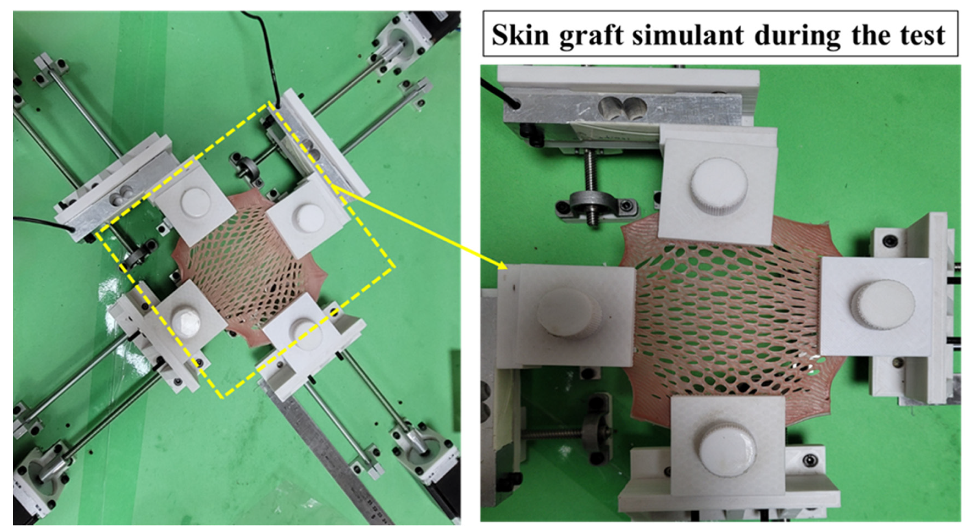
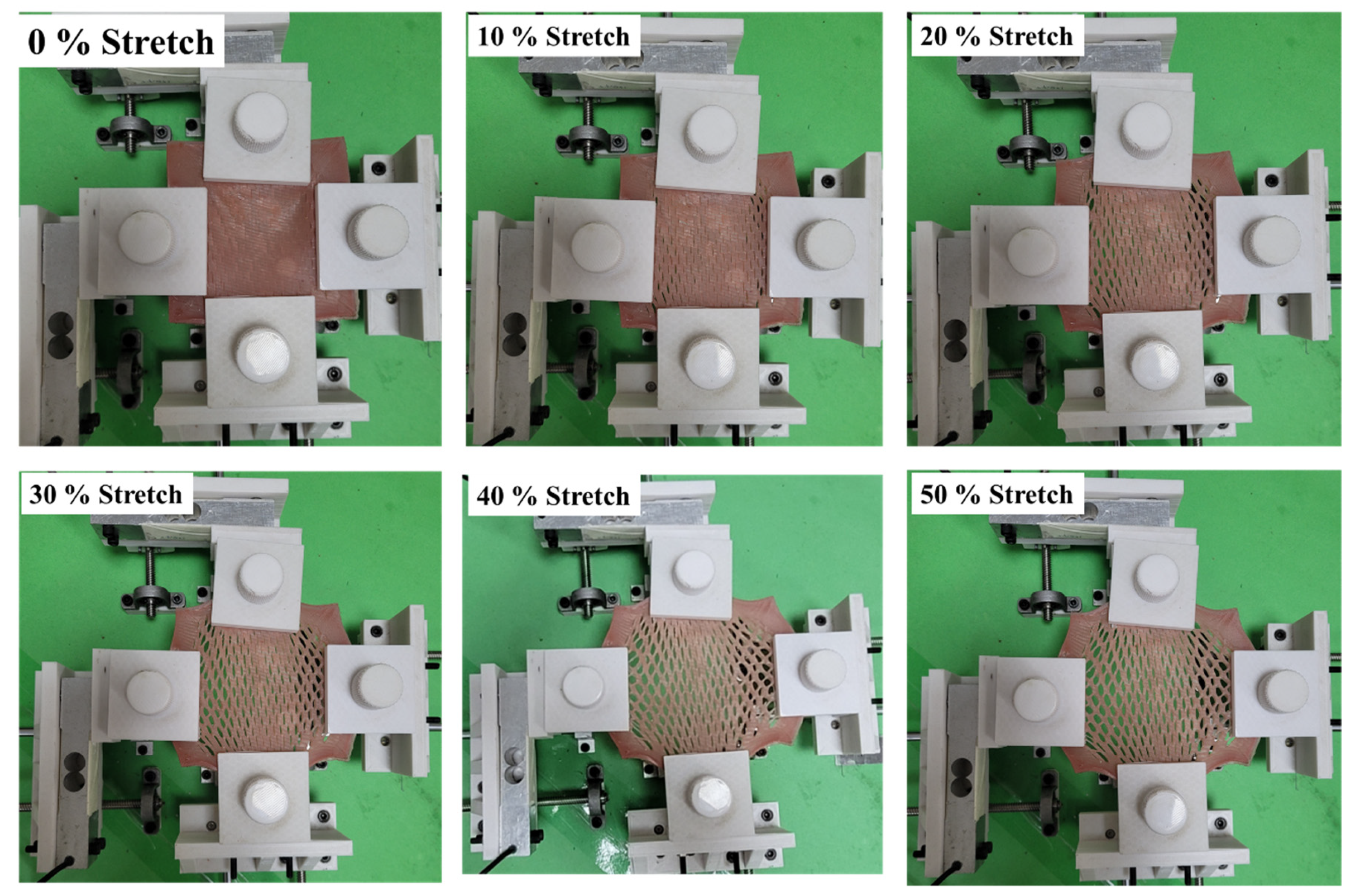
3.1. Biaxial Expansion of Anisotropic Synthetic Skin Grafts

Figure 6 illustrates the biaxial deformation of anisotropic synthetic skin grafts with increasing stretch up to a limit of 3.13 meshing ratio. At 10% stretch, the skin grafts started expanding, and the void area of the skin graft increased with the increasing stretch percentage. At 50% stretch, the skin graft showed a maximum concertina pattern with the maximum void area between two consecutive slits. For 0% stretch, the void area of all the synthetic skin grafts will be the same as the area of the 3D-printed part (i.e., 5 mm2), which was used to develop the synthetic skin grafts. Table 1 shows the void area of different stretch levels, and the value of the maximum void area was 33.51 mm2. From 0% to 50% stretching, the void area was increased approximately 7 times (570%).

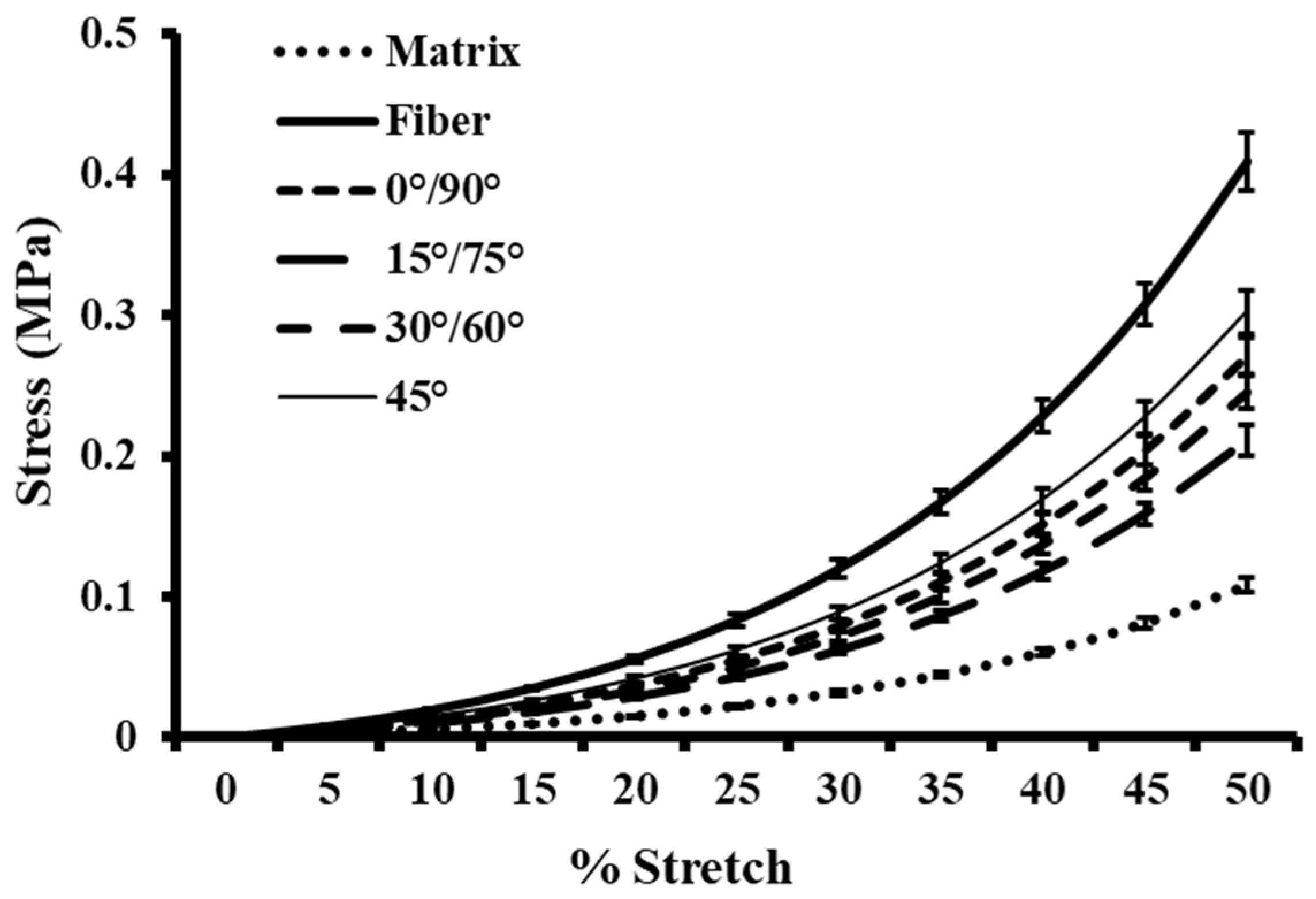
3.2. Biomechanical Behavior of Anisotropic One-Layer Synthetic Skin Grafts

The biaxial stress analysis of one-layer anisotropic synthetic skin grafts is shown in Figure 7. In the figure, the 0° or 90°, 15° or 75°, and 30° or 60° skin grafts show the same stress value. Five tests of each sample were conducted to calculate the average stress values of each anisotropic synthetic skin graft. The maximum and minimum value of stress was 0.30 MPa and 0.21 MPa, respectively. The synthetic skin graft with a 45° orientation shows the maximum stress value, and the 15° skin graft shows the minimum stress value. All the synthetic skin grafts show stress in the range of the matrix and fiber (i.e., 0.4 MPa and 0.1 MPa). In a previous study, Capek et al. [1] studied the effect of langer lines in skin grafting. They observed the maximum stress values of 2.52 MPa using FEA. Similarly, Gupta et al. [2] developed isotropic synthetic skin grafts and studied the effect of the slit size, spacing, and orientation under uniaxial loading conditions. The maximum stress observed in their study was 0.35 MPa in low spacing between the skin grafts. The induced stress value was 16.6% higher than this study. This may be due to different skin graft designs and loading conditions. Overall, these one-layer skin grafts will be used for the surgical training of medical students. Without ethical and biosafety issues, medical students will learn different skin grafting techniques for precise surgery.

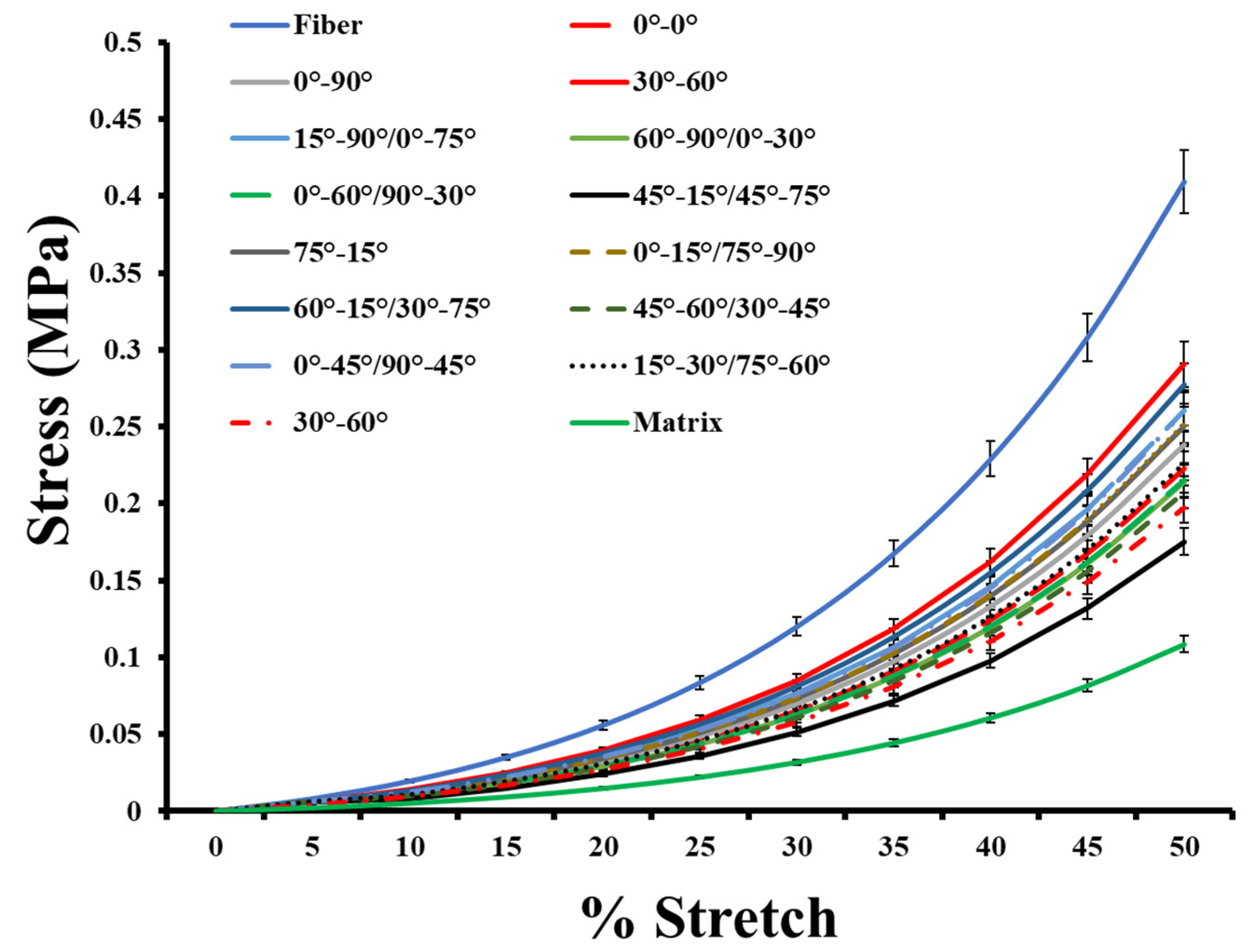
3.3. Biomechanical Behavior of Anisotropic Two-Layer Synthetic Skin Grafts

The stress analysis of two-layer synthetic skin grafts is shown in Figure 8. From the two-layer skin graft results, the maximum stress value was observed in the 30°–60° synthetic skin grafts. Overall, these two-layer skin grafts will be required for the purpose of training medical students in various surgical techniques. Medical students will be able to learn a variety of skin grafting techniques for precision surgery. In addition, this study will help students understand the biomechanics of skin grafts.

3.4. Hyperelastic Modelling of Anisotropic Synthetic Skin Grafts

Hyperelastic curve fit standards were used to characterize the stress and stretch response of the synthetic skin grafts, as discussed in Section 2. The averages of five stress versus strain results of the synthetic skin graft tested at 24 mm/min strain rate (shown in Figure 5) were determined. Table 2 shows the constant coefficients of neo-Hookean. It summarizes the coefficients and R2 values, which fall within 0.88 < R2 < 1. This model has one curve fit coefficient (c1), and the maximum value was observed in the 60°–15°-oriented skin graft model. Table 3 shows the constant coefficients of the Mooney–Rivlin model. It summarizes the coefficients and R2 values, which fall within 0.91 < R2 < 1. This model has two curve fit coefficients (c1 and c1), and the maximum correlation was observed in the 0°-oriented skin graft model. Table 4 shows the constant coefficients of the Mooney–Rivlin model. It summarizes the coefficients and R2 values, which fall within 0.89 < R2 < 1.

4. Discussions

The purpose of the study is to quantify the actual expansion offered by different types of skin grafts, specifically those with high claimed expansion ratios (e.g., 1:3). The study aims to build upon previous literature that has reported much lower expansion with actual skin grafts. To achieve this goal, this study used biofidelic synthetic skin to model skin grafts and measure their possible expansion. Additionally, the study aims to examine the effect of Langer lines on skin graft expansion and the grafts’ mechanical properties. Langer lines are natural lines of tension within the skin, which vary across body locations and impart anisotropy to the skin. By understanding the effect of Langer lines on skin graft expansion, the study aims to provide insight into the real expansion potential of skin grafts at different body locations.
Several steps were followed to design these single- and multi-layer synthetic skin grafts. First, a suitable material composition was selected for the matrix and fibers to develop the anisotropic synthetic skin. Second, different molds were designed for different fiber orientations and for hosting the material compositions for the fiber and matrix. The designs were printed using a high-definition 3D printer. Third, the material for the fibers was poured first into the channels in the mold, and then left to set for 30 min. Fourth, the material for the matrix was poured on top of the partially set fibers and filled the entire mold after 30 min; it was then left to set for 8 h. After 8 h, the fibers and matrix were integrated, and the synthetic skin sample could be removed from the mold. Fifth, synthetic skin graft development was conducted using stencils with the slit cutting pattern as per the meshing ratios (e.g., 1:3) fabricated using a 3D printer and followed by using a knife to cut the slits. Mechanical testing was conducted on a biaxial testing device and compared with the literature to ensure consistent skin graft mimicking. The effect of the fiber orientations on the expansion, void areas, and mechanical properties were characterized. A maximum average meshing ratio of 3.13 was estimated for single layers and a 15° orientation at 50% stretch. Across the one-layer models, the synthetic skin grafts with 15° fiber orientation showed the minimum induced stresses and maximum expansion. Across the two-layer synthetic skin grafts, the one with 45°–15° fiber orientation showed the minimum stress values and highest expansion. Different hyperelastic models were employed to estimate the curve fit coefficients with a high degree of correlation. These anisotropic synthetic skin grafts were developed to understand the effect of fibrous layers and orientation on skin graft expansion.
Our study results can be compared with several works in the literature. Recently, Gupta et al. [66] performed a computational analysis of skin grafts with varying slit orientations from 0° to 90°. In their study, all the skin grafts were tested computationally under uniaxial loading conditions, and the orientation showed a significant effect on the overall expansion of the skin grafts, consistent with our findings. There have been very few studies that model the effects of anisotropy on skin properties, and no such studies on skin grafts [2,38,47,48,67,68]. A recent study by Makode et al. [38] developed a single-layer anisotropic synthetic skin using a multi-part elastomer and performed uniaxial analysis on a variety of anisotropic synthetic skin. Following a similar procedure, the current work was focused on developing single- and multilayer anisotropic synthetic skin and novel synthetic skin grafts, and testing them under realistic biaxial stretching applied during the clinical implementation of skin grafts. The hyperelastic curve fit models were used to characterize the stress versus stretch responses of the synthetic skin grafts, similar to previous studies [2,38,47,48]. The coefficients not only had similar reported ranges, but the R2 values were also within a reasonable range (i.e., 0.88 < R2 < 1).
There are a few limitations of this study, which should be acknowledged. Square-shaped synthetic skin grafts with a constant thickness were studied, which is one ideal case of the range of skin graft shapes and thicknesses employed clinically. The cuts made in the grafts were not edge to edge and this could affect the results. No cadaveric skin or animal skins were tested due to ethical and biosafety issues. In addition, no biological investigation was conducted to study the effect of skin graft models on wound healing. In future studies, all these limitations will be addressed to better understand the effectiveness and shortcomings of the traditional graft variants.

5. Conclusions

In this work, anisotropic synthetic skin grafts were developed to understand the effect of fiber layers and orientations on skin graft expansion and its properties. A soft elastomer material-based framework was used to develop biofidelic anisotropic synthetic skin with one-layer and two-layers, and 3:1 meshing-based incision patterns were projected to fabricate a wide range of synthetic skin grafts (N = 100). Under clinically relevant biaxial stretch loading, the expansion in terms of the meshing ratio, void area, and stress–strain responses were estimated. All the synthetic skin grafts showed stress–strain responses below that of skin. The maximum observed void area was within the range of traditional skin grafts. A maximum average meshing ratio of 3.13 was estimated for single layers and 15° orientation at 50% stretch. Across the one-layer models, the synthetic skin grafts with a 15° fiber orientation showed the minimum induced stresses and maximum expansion. Across the two-layer synthetic skin grafts, the one with a 45°–15° fiber orientation showed the minimum stress values and highest expansion. Different hyperelastic models were employed to estimate the curve fit coefficients. These nonlinear material characterization models can be beneficial for the computational study of skin grafts. To date, the effect of Langar line orientations on a skin graft’s expansion properties have not been studied either through experiments or computationally. The current work attempts to understand the effect of all possible Langar line orientations on skin graft expansion. This topic is relatively original in this field and can provide a new target for clinical burn treatment. Additionally, it can provide a reference for the clinical use of the most suitable skin graft.
Overall, this study shows that skin’s fiber orientation significantly affects skin graft expansion, with generation of clinically reasonable void areas and stresses. The developed synthetic skin grafts could be indispensable for training medical students and further understanding of the biomechanics of skin grafts for improving burn surgery outcomes.

Author Contributions

A.C., V.G. and R.S. contributed substantially to the conception and design of the work; V.G. to the acquisition and analysis of the literature; and V.G. and R.S. to the interpretation of data for the work. Additionally, V.G. and A.C. contributed to drafting the work, while A.C., V.G. and R.S. revised it critically for important intellectual content. All authors have read and agreed to the published version of the manuscript.

Funding

This research received no external funding.

Institutional Review Board Statement

Not applicable.

Informed Consent Statement

Not applicable.

Data Availability Statement

The datasets generated during and/or analyzed during the current study are not publicly available due to large dataset but are available from the corresponding author on reasonable request.

Acknowledgments

This paper and research would not have been possible without the exceptional support A.C. and his facility provided via the Indian Institute of Technology, Delhi (IIT-D), India.

Conflicts of Interest

The authors declare no conflict of interest.

References

  1. Capek, L.; Flynn, C.; Molitor, M.; Chong, S.; Henys, P. Graft orientation influences meshing ratio. Burns 2018, 44, 1439–1445. [Google Scholar] [CrossRef]
  2. Gupta, V.; Chanda, A. Biomechanics of skin grafts: Effect of pattern size, spacing and orientation. Eng. Res. Express 2022, 4, 015006. [Google Scholar] [CrossRef]
  3. Johnson, T.M.; Ratner, D.; Nelson, B.R. Soft tissue reconstruction with skin grafting. J. Am. Acad. Dermatol. 1992, 27, 151–165. [Google Scholar] [CrossRef]
  4. Marín-Martínez, F.M.; Martínez-Valls, P.L.G.; Dekalo, S.; Weiss, J.; Haran, O. Aesthetic and Functional Results after Single- and Two-Stage Resection and Reconstruction of Penile Paraffinomas—Experience from Two Tertiary Centers and a Surgical Management Algorithm. Urology 2023, 171, 227–235. [Google Scholar] [CrossRef]
  5. Kohlhauser, M.; Luze, H.; Nischwitz, S.P.; Kamolz, L.P. Historical evolution of skin grafting—A journey through time. Medicina 2021, 57, 348. [Google Scholar] [CrossRef]
  6. Khan, Z.; Utheim, T.P.; Byholt, M.; Fiabema, T.; Sylvester-Jensen, H.C.; Tønseth, K.A. Hudtransplantasjon. Tidsskr. Nor. Laegeforening 2022, 142, 671. [Google Scholar] [CrossRef]
  7. Singh, G.; Gupta, V.; Chanda, A. Mechanical Characterization of Rotating Triangle Shaped Auxetic Skin Graft Simulants. Facta Univ. Ser. Mech. Eng. 2022, 1–16. [Google Scholar] [CrossRef]
  8. Gupta, S.; Gupta, V.; Chanda, A. Biomechanical modeling of novel high expansion auxetic skin grafts. Int. J. Numer. Method. Biomed. Eng. 2022, 38, e3586. [Google Scholar] [CrossRef] [PubMed]
  9. Persinal-Medina, M.; Llames, S.; Chacón, M.; Vázquez, N.; Pevida, M.; Alcalde, I.; Alonso-Alonso, S.; Martínez-López, L.M.; Merayo-Lloves, J.; Meana, A. Polymerizable Skin Hydrogel for Full Thickness Wound Healing. Int. J. Mol. Sci. 2022, 23, 4837. [Google Scholar] [CrossRef] [PubMed]
  10. Jeschke, M.G.; Van Baar, M.E.; Choudhry, M.A.; Chung, K.K.; Gibran, N.S.; Logsetty, S. Burn injury. Nat. Rev. Dis. Prim. 2020, 6, 11. [Google Scholar] [CrossRef] [PubMed]
  11. Shukla, S.; Behera, B.K. Auxetic fibrous materials and structures in medical engineering–A review. Bioeng. Transl. Med. 2022, 7, 1–12. [Google Scholar] [CrossRef]
  12. Liu, T.; Qiu, C.; Lu, H.; Li, H.; Zhu, S.; Ma, L. A novel recombinant human collagen hydrogel as minced split-thickness skin graft overlay to promote full-thickness skin defect reconstruction. Burns 2023, 49, 169–181. [Google Scholar] [CrossRef]
  13. Ozhathil, D.K.; Tay, M.W.; Wolf, S.E.; Branski, L.K. A narrative review of the history of skin grafting in burn care. Medicina 2021, 57, 380. [Google Scholar] [CrossRef]
  14. Chen, Q.; Zhang, J.; Wang, B.; Wang, Y.; Kang, C.; Zhang, Q. Total Auricular Reconstruction Using a Single Extended Postauricular Flap without Skin Grafting in Two Stages: Experiences of 106 Cases. Aesthetic Plast. Surg. 2020, 44, 365–372. [Google Scholar] [CrossRef]
  15. Schlottmann, F.; Bucan, V.; Vogt, P.M.; Krezdorn, N. A short history of skin grafting in burns: From the gold standard of autologous skin grafting to the possibilities of allogeneic skin grafting with immunomodulatory approaches. Medicina 2021, 57, 225. [Google Scholar] [CrossRef]
  16. Łabuś, W.; Kitala, D.; Klama-Baryła, A.; Szapski, M.; Smętek, W.; Kraut, M.; Poloczek, R.; Glik, J.; Pielesz, A.; Binias, D.; et al. A new approach to the production of a biovital skin graft based on human acellular dermal matrix produced in-house, in vitro revitalized internally by human fibroblasts and keratinocytes on the surface. J. Biomed. Mater. Res. Part B Appl. Biomater. 2019, 108, 1281–1294. [Google Scholar] [CrossRef] [PubMed]
  17. Larson, K.W.; Austin, C.L.; Thompson, S.J. Treatment of a full-thickness burn injury with novosorb biodegradable temporizing matrix and recell autologous skin cell suspension: A case series. J. Burn Care Res. 2020, 41, 215–219. [Google Scholar] [CrossRef] [PubMed]
  18. Yoon, J.; Yoon, D.; Lee, H.; Lee, J.; Jo, S.; Kym, D.; Yim, H.; Hur, J.; Chun, W.; Kim, G.; et al. Wound healing ability of acellular fish skin and bovine collagen grafts for split-thickness donor sites in burn patients: Characterization of acellular grafts and clinical application. Int. J. Biol. Macromol. 2022, 205, 452–461. [Google Scholar] [CrossRef]
  19. Rijpma, D.; Claes, K.; Hoeksema, H.; de Decker, I.; Verbelen, J.; Monstrey, S.; Pijpe, A.; van Zuijlen, P.; Vries, A.M.-D. The Meek micrograft technique for burns; review on its outcomes: Searching for the superior skin grafting technique. Burns 2022, 48, 1287–1300. [Google Scholar] [CrossRef]
  20. Lari, A.R.; Gang, R.K. Expansion technique for skin grafts (Meek technique) in the treatment of severely burned patients. Burns 2001, 27, 61–66. [Google Scholar] [CrossRef]
  21. Kreis, R.; Mackie, D.; Vloemans, A.; Hermans, R.; Hoekstra, M. Widely expanded postage stamp skin grafts using a modified Meek technique in combination with an allograft overlay. Burns 1993, 19, 142–145. [Google Scholar] [CrossRef]
  22. Vandeput, J.; Nelissen, M.; Tanner, J.C.; Boswick, J. A review of skin meshers. Burns 1995, 21, 364–370. [Google Scholar] [CrossRef]
  23. Karaçal, N.; Ambarcioǧlu, Ö.; Topal, U.; Gülçelik, N.; Kutlu, N. Skin graft mesher: An easy method of cartilage graft dicing. Plast. Reconstr. Surg. 2004, 114, 826–828. [Google Scholar] [CrossRef]
  24. Noureldin, M.A.; Said, T.A.; Makeen, K.; Kadry, H.M. Comparative study between skin micrografting (Meek technique) and meshed skin grafts in paediatric burns. Burns 2022, 48, 1632–1644. [Google Scholar] [CrossRef]
  25. Kan, T.; Takahagi, S.; Kawai, M.; Ashizawa, S.; Matsubara, D.; Mizuno, H.; Tanaka, A.; Hide, M. Calculation of practical skin donor area for meshed skin grafting in real-world surgery. Dermatol. Ther. 2020, 33, e14393. [Google Scholar] [CrossRef]
  26. Hohmann, E. Editorial Commentary: Long Head Biceps Tendon Can Be Used Like a Split Skin Graft: Mesh It and Augment Rotator Cuff Repairs. Arthrosc. J. Arthrosc. Relat. Surg. 2022, 38, 49–50. [Google Scholar] [CrossRef]
  27. Singh, M.; Nuutila, K.; Collins, K.C.; Huang, A. Evolution of skin grafting for treatment of burns: Reverdin pinch grafting to Tanner mesh grafting and beyond. Burns 2017, 43, 1149–1154. [Google Scholar] [CrossRef]
  28. Guo, Y.; Song, Y.; Xiong, S.; Wang, T.; Liu, W.; Yu, Z.; Ma, X. Mechanical Stretch Induced Skin Regeneration: Molecular and Cellular Mechanism in Skin Soft Tissue Expansion. Int. J. Mol. Sci. 2022, 23, 9622. [Google Scholar] [CrossRef] [PubMed]
  29. Uhljar, L.; Ambrus, R. Electrospinning of Potential Medical Devices (Wound Dressings, Tissue Engineering Scaffolds, Face Masks) and Their Regulatory Approach. Pharmaceutics 2023, 15, 417. [Google Scholar] [CrossRef]
  30. Byun, S.; Kim, S.; Lee, H.; Lim, H.; Kim, J.; Lee, U.; Lee, J.; Park, S.; Kim, S.; Song, J.-D.; et al. Soft tissue expander for vertically atrophied alveolar ridges: Prospective, multicenter, randomized controlled trial. Clin. Oral Implant. Res. 2020, 31, 585–594. [Google Scholar] [CrossRef]
  31. Gawande, D.D.; Singh, A.; Ukey, V.T.; Madan, R.S.; Manjula, V.; Shrivastava, S. Tissue expansion in oral and maxillofacial surgery. Int. J. Heal. Sci. 2022, 14, 3329–3339. [Google Scholar] [CrossRef]
  32. Stepniewski, A.; Lehmann, W.; Schilderoth, M.; Behringer, D.; Emmerich, N.; Daugardt, J.; von der Brelie, C.; Kauffmann, P.; Felmerer, G. The Efficacy of Local Flaps in the Treatment of Traumatic Scalp Defects. J. Neurol. Surg. Part A: Central Eur. Neurosurg. 2021, 83, 330–337. [Google Scholar] [CrossRef] [PubMed]
  33. Hong, J.P.; Kwon, J.G. Flaps in Plastic Surgery. Textb. Plast. Reconstr. Surg. 2022, 103–123. [Google Scholar] [CrossRef]
  34. Taghizadeh, R.; Gilbert, P.M. Comparison of commonly used mesher types in burns surgery revisited. Burns 2008, 34, 109–110. [Google Scholar] [CrossRef] [PubMed]
  35. Pripotnev, S.; Papp, A. Split thickness skin graft meshing ratio indications and common practices. Burns 2017, 43, 1775–1781. [Google Scholar] [CrossRef]
  36. Lyons, J.L.; Kagan, R.J. The True Meshing Ratio of Skin Graft Meshers. J. Burn. Care Res. 2014, 35, 257–260. [Google Scholar] [CrossRef]
  37. Henderson, J.; Arya, R.; Gillespie, P. Skin graft meshing, over-meshing and cross-meshing. Int. J. Surg. 2012, 10, 547–550. [Google Scholar] [CrossRef]
  38. Makode, S.; Singh, G.; Chanda, A. Development of novel anisotropic skin simulants. Phys. Scr. 2021, 96, 125019. [Google Scholar] [CrossRef]
  39. Sharma, S.; Batra, S. Recent advances of chitosan composites in artificial skin: The next era for potential biomedical application. Mater. Biomed. Eng. Nanobiomaterials Tissue Eng. 2019, 97–119. [Google Scholar] [CrossRef]
  40. Snyder, D.E.; Sapper, E.D. See Me, Feel Me, Touch Me, Heal Me: A Contextual Overview of Conductive Polymer Composites as Synthetic Human Skin. J. Compos. Sci. 2022, 6, 141. [Google Scholar] [CrossRef]
  41. Rajab, T.K.; O’malley, T.J.; Tchantchaleishvili, V. Decellularized scaffolds for tissue engineering: Current status and future perspective. Artif. Organs 2020, 44, 1031–1043. [Google Scholar] [CrossRef] [PubMed]
  42. Charbe, N.B.; Tambuwala, M.; Palakurthi, S.S.; Warokar, A.; Hromić-Jahjefendić, A.; Bakshi, H.; Zacconi, F.; Mishra, V.; Khadse, S.; Aljabali, A.A.; et al. Biomedical applications of three-dimensional bioprinted craniofacial tissue engineering. Bioeng. Transl. Med. 2022, 8, e10333. [Google Scholar] [CrossRef]
  43. Joseph, J.; Deshmukh, K.; Tung, T.T.; Chidambaram, K.; Pasha, S.K.K. 3D Printing Technology of Polymer Composites and Hydrogels for Artificial Skin Tissue Implementations. In Lecture Notes in Bioengineering; Springer: Berlin/Heidelberg, Germany, 2019; pp. 205–233. [Google Scholar]
  44. Veerabagu, U.; Palza, H.; Quero, F. Review: Auxetic Polymer-Based Mechanical Metamaterials for Biomedical Applications. ACS Biomater. Sci. Eng. 2022, 8, 2798–2824. [Google Scholar] [CrossRef] [PubMed]
  45. Benítez, J.M.; Montáns, F.J. The mechanical behavior of skin: Structures and models for the finite element analysis. Comput. Struct. 2017, 190, 75–107. [Google Scholar] [CrossRef]
  46. Chanda, A. Biomechanical Modeling of Human Skin Tissue Surrogates. Biomimetics 2018, 3, 18. [Google Scholar] [CrossRef]
  47. Annaidh, A.N.; Bruyère-Garnier, K.; Destrade, M.; Gilchrist, M.D.; Otténio, M. Characterization of the anisotropic mechanical properties of excised human skin. J. Mech. Behav. Biomed. Mater. 2012, 5, 139–148. [Google Scholar] [CrossRef]
  48. Chanda, A.; Chatterjee, S.; Gupta, V. Soft composite based hyperelastic model for anisotropic tissue characterization. J. Compos. Mater. 2020, 54, 4525–4534. [Google Scholar] [CrossRef]
  49. Saager, R.B.; Kondru, C.; Au, K.; Sry, K.; Ayers, F.; Durkin, A.J. Multilayer silicone phantoms for the evaluation of quantitative optical techniques in skin imaging. In Proceedings of the Design and Performance Validation of Phantoms Used in Conjunction with Optical Measurement of Tissue II, San Francisco, CA, USA, 24 February 2010; p. 756706. [Google Scholar] [CrossRef]
  50. Qi, H.J.; Joyce, K.; Boyce, M.C. Durometer Hardness and the Stress-Strain Behavior of Elastomeric Materials. Rubber Chem. Technol. 2003, 76, 419–435. [Google Scholar] [CrossRef]
  51. Pissarenko, A.; Meyers, M.A. The materials science of skin: Analysis, characterization, and modeling. Prog. Mater. Sci. 2020, 110, 100634. [Google Scholar] [CrossRef]
  52. Tseng, H.C.; Chang, R.Y.; Hsu, C.H. Comparison of recent fiber orientation models in injection molding simulation of fiber-reinforced composites. J. Thermoplast. Compos. Mater. 2020, 33, 35–52. [Google Scholar] [CrossRef]
  53. Rosin, N.L.; Agabalyan, N.; Olsen, K.; Martufi, G.; Gabriel, V.; Biernaskie, J.; Di Martino, E.S. Collagen structural alterations contribute to stiffening of tissue after split-thickness skin grafting. Wound Repair Regen. 2016, 24, 263–274. [Google Scholar] [CrossRef]
  54. Yang, Y.; Song, X.; Li, X.; Chen, Z.; Zhou, C.; Zhou, Q.; Chen, Y. Recent Progress in Biomimetic Additive Manufacturing Technology: From Materials to Functional Structures. Adv. Mater. 2018, 30, e1706539. [Google Scholar] [CrossRef] [PubMed]
  55. Singh, G.; Gupta, V.; Chanda, A. Artificial skin with varying biomechanical properties. Mater. Today Proc. 2022, 62, 3162–3166. [Google Scholar] [CrossRef]
  56. Gajewski, M.; Szczerba, R.; Jemioło, S. Modelling of elastomeric bearings with application of Yeoh hyperelastic material model. in Procedia Eng. 2015, 111, 220–227. [Google Scholar] [CrossRef]
  57. Wissler, M.; Mazza, E. Modeling and simulation of dielectric elastomer actuators. Smart Mater. Struct. 2005, 14, 1396. [Google Scholar] [CrossRef]
  58. Mohammadi, A.K.; Barforooshi, S.D. Nonlinear Forced Vibration Analysis of Dielectric-Elastomer Based Micro-Beam with Considering Yeoh Hyper-Elastic Model. Lat. Am. J. Solids Struct. 2017, 14, 643–656. [Google Scholar] [CrossRef]
  59. Barforooshi, S.D.; Mohammadi, A.K. Study Neo-Hookean and Yeoh Hyper-Elastic Models in Dielectric Elastomer-Based Micro-Beam Resonators. Lat. Am. J. Solids Struct. 2016, 13, 1823–1837. [Google Scholar] [CrossRef]
  60. Khaniki, H.B.; Ghayesh, M.H.; Chin, R.; Amabili, M. Hyperelastic structures: A review on the mechanics and biomechanics. Int. J. Non. Linear. Mech. 2023, 148, 104275. [Google Scholar] [CrossRef]
  61. Wex, C.; Arndt, S.; Stoll, A.; Bruns, C.; Kupriyanova, Y. Isotropic incompressible hyperelastic models for modelling the mechanical behaviour of biological tissues: A review. Biomed. Eng./Biomed. Tech. 2015, 60, 577–592. [Google Scholar] [CrossRef]
  62. Khaniki, H.B.; Ghayesh, M.H.; Chin, R.; Amabili, M. A review on the nonlinear dynamics of hyperelastic structures. Nonlinear Dyn. 2022, 110, 963–994. [Google Scholar] [CrossRef]
  63. Chagnon, G.; Rebouah, M.; Favier, D. Hyperelastic Energy Densities for Soft Biological Tissues: A Review. J. Elast. 2014, 120, 129–160. [Google Scholar] [CrossRef]
  64. Gallagher, J.; Ní Anniadh, A.; Bruyere, K.; Otténio, M.; Xie, H.; Gilchrist, M.D. Dynamic tensile properties of human skin. In Proceedings of the 2012 IRCOBI Conference Proceedings—International Research Council on the Biomechanics of Injury, Dublin, Ireland, 2–14 September 2012; pp. 494–502. [Google Scholar]
  65. Chanda, A.; Graeter, R. Human Skin-Like Composite Materials for Blast Induced Injury Mitigation. J. Compos. Sci. 2018, 2, 44. [Google Scholar] [CrossRef]
  66. Gupta, V.; Singh, G.; Chanda, A. Development and testing of skin grafts models with varying slit orientations. Mater. Today Proc. 2022, 62, 3462–3467. [Google Scholar] [CrossRef]
  67. Chavan, V.; Chittoria, R.; Elankumar, S.; Reddy, K.S.; Aggarwal, A.; Gupta, S.; Reddy, C.L.; Mohan, P.L.B. Pixel Grafting: A Novel Skin Graft Expansion Technique. J. Cutan. Aesthet. Surg. 2021, 14, 229. [Google Scholar] [CrossRef] [PubMed]
  68. Koetsier, K.S.; Wong, J.N.; Muffley, L.A.; Carrougher, G.J.; Pham, T.N.; Gibran, N.S. Prospective observational study comparing burn surgeons’ estimations of wound healing after skin grafting to photo-assisted methods. Burns 2019, 45, 1562–1570. [Google Scholar] [CrossRef] [PubMed]
Figure 1. Schematic representation of synthetic skin graft technology development.
Dermato 03 00010 g001
Figure 2. Different molds and synthetic skin with varying angles.
Dermato 03 00010 g002
Figure 3. Two-layer anisotropic synthetic skin with varying fiber orientations.
Dermato 03 00010 g003
Figure 4. Schematic of the development of anisotropic synthetic skin grafts with (a) 3D-printed graft meshing slits. (b) Anisotropic synthetic skin fabrication; (c) projection of slit patterns on synthetic skin; (d) resultant synthetic skin grafts.
Dermato 03 00010 g004
Figure 5. Schematic of biaxial testing setup with attached synthetic skin graft.
Dermato 03 00010 g005
Figure 6. Schematic representation of skin graft expansion.
Dermato 03 00010 g006
Figure 7. Stress analysis of one-layer anisotropic synthetic skin grafts.
Dermato 03 00010 g007
Figure 8. Stress analysis of two-layer anisotropic synthetic skin grafts.
Dermato 03 00010 g008
Table 1. Void area and meshing ratio calculation during synthetic skin graft expansion.
Anisotropic Skin GraftUnit Cell Void Area (mm2)Average Meshing Ratio
At 0% stretch51
At 10% stretch8.33 ± 10%1.33
At 20% stretch10.86 ± 10%1.71
At 30% stretch16.6 ± 10%2.14
At 40% stretch26.69 ± 10%2.61
At 50% stretch33.51 ± 10%3.13
Table 2. Neo-Hookean hyperelastic model estimations.
Anisotropic Skin Graft ModelNeo-Hookean Curve Fit CoefficientR2
c1
0.08140.9972
15°0.07020.9246
30°0.07940.9968
45°0.09490.9981
0°–0°0.07840.9645
0°–90°0.07850.9950
30°–60°0.10370.9771
15°–90°/0°–75°0.08620.9957
60°–90°/0°–30°0.07510.8986
0°–60°/90°–30°0.07410.9841
45°–15°/45°–75°0.06300.9901
75°–15°0.09920.8862
0°–15°/75°–90°0.08720.9893
60°–15°/30°–75°0.10490.9379
45°–60°/30°–45°0.07170.9877
0°–45°/90°–45°0.09190.9014
15°–30°/75°–60°0.08290.9618
Table 3. Mooney–Rivlin hyperelastic model estimations.
Anisotropic Skin Graft ModelMooney–Rivlin Curve Fit CoefficientsR2
c1c2
0.08140.00010.9972
15°0.00010.09750.9528
30°0.07940.00010.9968
45°0.09490.00010.9981
0°–0°0.00000.10910.9898
0°–90°0.07850.00010.9950
30°–60°0.00960.13070.9924
15°–90°/0°–75°0.07180.02010.9967
60°–90°/0°–30°0.00010.10480.9404
0°–60°/90°–30°0.00010.10280.9971
45°–15°/45°–75°0.0630.00010.9901
75°–15°0.00010.13900.9445
0°–15°/75°–90°0.00950.10780.9983
60°–15°/30°–75°0.00010.14650.9773
45°–60°/30°–45°0.03550.05030.9928
0°–45°/90°–45°0.00010.12770.9180
15°–30°/75°–60°0.00010.11540.9898
Table 4. Yeoh hyperelastic model estimations.
Anisotropic Skin Graft ModelYeoh Curve Fit CoefficientsR2
c1c2c3
0.07300.01050.00010.9986
15°0.07020.00010.00010.9246
30°0.07930.00010.00010.9968
45°0.09140.00440.00010.9975
0°–0°0.07840.00010.00010.9645
0°–90°0.07850.00010.00010.9950
30°–60°0.10370.00010.00010.9771
15°–90°/0°–75°0.08620.00010.00010.9957
60°–90°/0°–30°0.07510.00010.00010.8986
0°–60°/90°–30°0.07410.00010.00010.9841
45°–15°/45°–75°0.05180.01400.00010.9926
75°–15°0.09920.00010.00010.8862
0°–15°/75°–90°0.08720.00010.00010.9893
60°–15°/30°–75°0.10490.00010.00010.9379
45°–60°/30°–45°0.07170.00010.00010.9877
0°–45°/90°–45°0.09190.00010.00010.9014
15°–30°/75°–60°0.08290.00010.00010.9618
Disclaimer/Publisher’s Note: The statements, opinions and data contained in all publications are solely those of the individual author(s) and contributor(s) and not of MDPI and/or the editor(s). MDPI and/or the editor(s) disclaim responsibility for any injury to people or property resulting from any ideas, methods, instructions or products referred to in the content.

