Review

Carbon Capture from CO2-Rich Natural Gas via Gas-Liquid Membrane Contactors with Aqueous-Amine Solvents: A Review

by
Guilherme Pereira da Cunha
,
José Luiz de Medeiros
* and
Ofélia de Queiroz F. Araújo
Escola de Química, Federal University of Rio de Janeiro, CT, E, Ilha do Fundão, Rio de Janeiro 21941-909, RJ, Brazil
*
Author to whom correspondence should be addressed.
Gases 2022, 2(3), 98-133; https://doi.org/10.3390/gases2030007
Submission received: 2 July 2022 / Revised: 29 July 2022 / Accepted: 17 August 2022 / Published: 1 September 2022
(This article belongs to the Section Natural Gas)

Abstract

:
Gas–liquid membrane contactor is a promising process intensification technology for offshore natural gas conditioning in which weight and footprint constraints impose severe limitations. Thanks to its potential for substituting conventional packed/trayed columns for acid-gas absorption and acid-gas solvent regeneration, gas-liquid membrane contactors have been investigated experimentally and theoretically in the past two decades, wherein aqueous-amine solvents and their blends are the most employed solvents for carbon dioxide removal from natural gas in gas-liquid membrane contactors. These efforts are extensively and critically reviewed in the present work. Experimentally, there are a remarkable lack of literature data in the context of gas–liquid membrane contactors regarding the following topics: water mass transfer; outlet stream temperatures; head-loss; and light hydrocarbons (e.g., ethane, propane, and heavier) mass transfer. Theoretically, there is a lack of complete models to predict gas-liquid membrane contactor operation, considering multicomponent mass balances, energy balances, and momentum balances, with an adequate thermodynamic framework for correct reactive vapor–liquid equilibrium calculation and thermodynamic and transport property prediction. Among the few works covering modeling of gas-liquid membrane contactors and implementation in professional process simulators, none of them implemented all the above aspects in a completely successful way.

Graphical Abstract

1. Introduction

The global population is continuously increasing, and it is foreseen that it will exceed 10 billion by 2050 [1]. In this scenario, natural gas (NG) exploration and production attract interest in meeting the growing world energy demand [2]. Moreover, NG plays a key role in the transition to renewable energy sources [3] as NG is the cleanest fossil fuel due to its high hydrogen/carbon ratio [4].
Proven NG reserves around the world are approximately 196.9 trillion cubic meters [4], but onshore NG reserves—with simpler production that is closer to consumers—are decreasing, while offshore NG reserves far from the coast and in deep waters are growing [5]. In this regard, oil production with associated NG in deep-waters and ultra-deep-waters usually presents high carbon dioxide (CO2) content and gas-to-oil ratio, which entail difficulties for gas processing in offshore rigs where there are weight/footprint limitations [6]. Due to complex logistics for NG production/transportation in the context of deep-water offshore rigs, high costs lead to significant offshore CO2-rich NG reserves being left unexplored. Albeit the existence of efficient technologies for onshore NG production, innovative low-cost technologies are necessary for deep-waters processing of CO2-rich NG [5].
The concept of carbon capture utilization and storage (CCUS) is necessary to allow a smooth transition from fossil energy to renewable energy to keep a profitable industrial operation. In CO2-rich NG processing, CO2 removed from NG is transported to a storage site [7]. Promising CO2 utilizations are enhanced oil recovery (EOR) in oil-and-gas reservoirs [8] or enhanced gas recovery (EGR) in gas reservoirs [9]. In CCUS-EOR or CCUS-EGR, CO2 is injected into reservoirs to increase oil and gas production. If the increase is high enough, the extra revenues can offset CO2 capture/transportation costs entailing profits [7].

1.1. Natural Gas Purification Requirements

Raw NG primarily contains methane (CH4) and secondarily ethane, propane, butanes, and heavier hydrocarbons. Other common constituents are CO2, hydrogen sulfide (H2S), water (H2O), nitrogen (N2), and trace components. Raw NG purification is necessary to meet gas pipeline specifications and market/environment regulations [10].
NG processing usually comprises: (i) H2S removal [11]; (ii) water dew-point adjustment (WDPA) via dehydration [12]; (iii) hydrocarbon dew-point adjustment (HCDPA) [10]; and (iv) CO2 removal. H2S causes pipeline/equipment corrosion, it is undesirable in combustion, and threatens human health and the environment [11]. WDPA is necessary mainly because water condensed from NG may form solid gas-hydrates under high-pressure and low-temperature typically found in subsea pipelines [12]. HCDPA is necessary to avoid hydrocarbon condensation in pipelines (safety and efficiency issues) and to recover valuable NG liquids [13]. Besides, HCDPA removes hydrocarbons to meet the heating value specification (Wobbe Indexes), ensuring adequate gas–turbine and combustion equipment operations minimizing emissions [5]. Finally, CO2 content is reduced to 2–3 mol%, increasing NG heating value, preventing solid CO2-hydrates, avoiding corrosion, and avoiding occupying pipeline capacity with inert [14].

1.2. Carbon Capture from CO2-Rich NG

Several technologies exist for carbon capture from CO2-rich NG. Pressure-swing adsorption (PSA) prescribes selective CO2 adsorption onto solid adsorbents at high-pressure conjugated with low-pressure CO2 desorption [15]. PSA issues comprehend the methane purity-recovery tradeoff [16] and the low-pressure CO2 release entailing compression costs [17].
Cryogenic distillation is considered for CO2 ≥ 10 mol% due to lesser energy consumption and footprint compared to chemical absorption [18]. However, since cryogenic distillation operates at temperatures below the CO2 triple-point [19], there is a risk of CO2 freeze-out (dry-ice) inside the equipment, causing blockage [18]. Moreover, high-pressure cryogenic columns are protected against pressure surges by blowdown valves, which under cryogenic conditions can lead to dry-ice formation via the Joule–Thomson effect [20].
In offshore CO2-rich NG processing, membrane permeation (MP) is adopted due to its low footprint, modularity, and flexibility to feed composition changes [21] and is recommended for high CO2 content NG [22]. However, thanks to its capacity-selectivity tradeoff [23], permeate methane losses are remarkable, and the low-pressure CO2-rich permeate imposes high compression costs [24].
Physical absorption (PhA) prescribes a physical solvent that dissolves CO2 at high-pressure [25], requiring high CO2 fugacity for high CO2 loadings [26]. PhA is much less energy-intense for solvent regeneration compared to chemical absorption at the expense of a low-pressure CO2 stripping [6]. PhA drawbacks comprise (i) low CO2/CH4 selectivity entailing CH4 losses in the stripped gas; (ii) low-pressure stripped gas entailing compression costs for EOR destination.
The most mature technology for CO2 and H2S removal from CO2-rich NG is chemical absorption (ChA), which is based on CO2 reactions with aqueous-alkanolamine solvents [27]. Aqueous-monoethanolamine (aqueous-MEA) and aqueous-methyl-diethanolamine (aqueous-MDEA) are the most used chemical solvents [28]. The main advantage is the high CO2/CH4 selectivity in a wide range of operation pressures [27] and this selectivity is particularly high at low CO2 fugacity [22]. ChA generally operates with packing columns that have beds of variously-shaped packings—e.g., Pall rings or Berl saddles—providing a high specific surface area for CO2 transfer. Packing columns are fed with lean solvent at the top and with raw NG at the bottom in countercurrent flows [29]. ChA drawbacks comprise: (i) high heat-ratio (kJ/kgCO2) solvent regeneration [28]; (ii) solvent degradation (oxidation and thermal degradation) causing corrosion and efficiency loss; (iii) low-pressure CO2 stripping entailing compression costs for EOR; (iv) hydraulic issues (e.g., foaming, channeling, flooding and entrainment) [29].
The gas-liquid membrane contactor (GLMC) combines MP and ChA advantages—without the respective drawbacks—becoming a promising solution for CO2-rich NG decarbonation [30]. In GLMC, the hollow-fiber membrane (HFM) provides a non-dispersive gas-liquid contact avoiding packing-columns hydraulic problems like foaming, channeling, flooding, and entrainment [31]. Comparatively, with MP, the selective chemical solvent and thousands of HFM inside the GLMC shell ensure high CO2/CH4 selectivity with low CH4 loss, high mass transfer area per shell, compactness, modularity, and easy scale-up, all desired attributes for CO2 removal from CO2-rich NG with aqueous-amine solvents in offshore rigs [22]. Comparatively, with conventional CO2 absorption packing columns, GLMC reaches reductions up to 70% and 66% in size and weight, respectively [32]. Angular indifference is another advantage of GLMC vis-à-vis the sway of floating offshore rigs [33].

1.3. Review Articles on GLMC: Highlights and Gaps

An overview with an appreciation of typical GLMC reviews is conducted. Table 1 condenses reviews on GLMC aspects and developments, while Table 2 condenses reviews on post-combustion carbon capture GLMC, which, despite being somewhat outside the scope—as operating conditions are different from NG processing counterparts—is kept in the analysis due to common particularities of both scenarios (e.g., isothermal modeling issues and low-pressure CO2 stripping GLMC). Table 3 analyzes general reviews on GLMC CO2 removal from NG.

1.4. The Present Work

This work intends to fill the gaps in common reviews on GLMC for NG decarbonation and solvent regeneration seen in Table 3. Common deficiencies of Table 3 reviews comprehend: (i) lack of rigorous high-pressure non-isothermal GLMC modeling; (ii) lack of rigorous estimation of thermodynamic properties under multi-reactive conditions; (iii) lack of consideration of thermal and compressibility effects under chemical reactions; and (iv) GLMC implementation in professional process simulators.
In this context, this work critically reviews experimental and theoretical GLMC studies focusing on two applications: (i) CO2 removal from CO2-rich NG considering high-pressure operation and H2O/H2S handling and (ii) low-pressure CO2 stripping for solvent regeneration. Section 2 reviews studies on GLMC principles, materials and configurations. Section 3 addresses experimental studies on the two mentioned applications. Section 4 critically reviews GLMC modeling for the two mentioned applications, including GLMC implementation in professional process simulators, analyzing model simplifications and limitations. Future prospects and concluding remarks are the object of Section 5.

2. GLMC: Principles, Materials, and Configurations

GLMC is modular equipment configured in batteries. Each GLMC module contains thousands of hydrophobic HFM tubes fixed into a shell-and-tube arrangement [51] in Figure 1. Equipment inclination translates into GLMC angular indifference [33].
GLMC is configurable as an absorber (for CO2 capture) or as a stripper (CO2 stripping for solvent regeneration). In both cases, GLMC has two feeds (where L is the molar flowrate of the GLMC liquid stream and V is the gas counterpart): (i) GLMC-absorber: NG feed V a b s o r b e r i n ; lean aqueous-amine solvent L a b s o r b e r i n [52]; (ii) GLMC-stripper: Sweep-gas (nitrogen [53] or steam [54]) V s t r i p p e r i n ; rich aqueous-amine solvent L s t r i p p e r i n .
GLMC modules can operate with parallel V and L flows (co-current contact) [55] or opposed V and L flows (counter-current contact) [56]. Whichever the case, V flows inside HFM tubes or on the shell-side, while L respectively flows on the shell-side or inside HFM tubes. Consequently, there are four different GLMC configurations shown in Figure 1: (a,b) apply counter-current contact; (c,d) apply parallel contact; (a,c) have L in shell-side and V inside HFM tubes; (b,d) have L inside HFM tubes and V in shell-side [57]. Since HFM is a physical barrier against phase dispersion, additional phase separation equipment is not necessary [37]. HFM also increases the interfacial area reducing equipment size [58].
GLMC is based on reactive-vapor-liquid-equilibrium (RVLE) since V and L streams are kept in direct contact through the HFM pores and relatively rapid chemical reactions occur in the liquid. In GLMC-absorber with chemical solvent, high CO2/CH4 selectivity is imposed by the aqueous solvent thanks to CH4 hydrophobicity [33] and selective CO2 conversion via liquid phase chemical reactions. When crossing the membranes, CH4 rapidly reaches its low solubility in the aqueous solvent, such that CH4 bubbles as a small vapor phase may form on the liquid side. As absorption chemical reactions between the solvent and CO2 (or H2S) are exothermic, the liquid temperature continuously increases, reducing CH4 solubility and raising CH4 fugacity over the liquid. Therefore, an L stream can be a single-phase liquid or a two-phase stream. Moreover, the CH4 bubbles on the solvent side contribute to stripping some CO2/H2S from the solvent, at the same time raising trans-membrane transport via reduction of CO2/H2S fugacities in the liquid [33].
On the other hand, in GLMC-absorber with physical solvent, CO2 does not react with the solvent, so species mass transfers and CO2/CH4 selectivity depend only on gas diffusivities into the solvent and solute solubilities in the solvent. In this case, CO2 Henry’s Law is frequently used for VLE predictions [59].
In GLMC, convective heat transfers occur due to temperature differences between (i) V and L streams across HFM; (ii) shell-side phase and shell outside. As molar isobaric heat capacity ( C ¯ P ) values imply V C ¯ P V < < L C ¯ P L , the L stream controls the temperature distribution; consequently, L and V temperature difference is near zero T V T L 0 at a given GLMC axial position due to convective interfacial heat transfer.
Water can transfer L→V or V→L, depending on the interfacial difference of H2O fugacities f ^ V H 2 O - f ^ L H 2 O , influenced by the water content of feeds and absorption heat effects. For counter-current GLMC, the lowest T V , T L values occur at the L inlet, which is also the V outlet position. As V approaches its outlet at water saturation, its temperature lowers and condensation can occur, turning V into a two-phase flow [33]. Additionally, the large absorption heat release can vaporize solvent on the L side [60]. Considering all these thermal effects, both L and V can be single-phase or two-phase streams at some GLMC point [33].
GLMC-stripper regenerates physical solvents (L) with nitrogen or steam as sweep-gas (V). A vacuum-driven pump can also be employed to reduce V pressure. Since CO2/H2S fugacities in the sweep-gas are lower than in the solvent, CO2/H2S move L→V enabling separation without heat supply [54]. As Figure 2 shows, CO2/H2S move V→L in GLMC-absorber and L→V in GLMC-stripper, while H2O moves V→L or L→V whether f ^ V H 2 O - f ^ L H 2 O > 0 or f ^ V H 2 O - f ^ L H 2 O < 0 . N2 transfer in GLMC-stripper is negligible since N2 is highly hydrophobic [53].

2.1. HFM for GLMC

Contrarily to MP, which uses dense selective membranes, GLMC adopts non-selective microporous HFM to allow V-L contact and selectivity is imposed by the solvent [61]. Figure 3 depicts how HFM works as a mass transfer barrier preventing phase dispersion [62]. Figure 3a represents direct V-L contact in tray columns or packing columns with phase dispersion. Figure 3b shows microporous HFM with gas-filled pores ensuring V-L contact with low mass transfer resistance [63]. However, during GLMC operation, the solvent may fill the pores (Figure 3c), increasing mass transfer resistance drastically and reducing transfer fluxes. This undesirable phenomenon compromises GLMC performance and is called membrane pore wetting (MPW) [62]. MPW is influenced by membrane characteristics (pores diameter, tortuosity, porosity, surface roughness), solvent surface tension, and operating conditions, while some solvents may favor MPW by affecting HFM hydrophobicity, morphology, and roughness. To avoid MPW, HFM material must be hydrophobic such as polypropylene (PP), polyvinylidene fluoride (PVDF), polytetrafluorethylene (PTFE), polyether ether ketone (PEEK), and solvents should have high surface tension, negligible vapor pressure and should not chemically attack HFM [41]. Figure 3d shows another solution against MPW wherein dense HFM CO2 permeable and solvent impermeable are used. However, dense HFM presents high transfer resistance and does not fit in the original GLMC concept of non-dispersive V-L contact [62]. A compromise solution uses composite HFM (Figure 3e) consisting of an ultrathin dense skin layer onto microporous support. The ultrathin layer is generally a fluorine-based hydrophobic material, while the microporous support—made of a cheaper material like PP—should be mechanically resistant, chemically stable, and highly porous to minimize transfer resistance [62].

2.2. Solvents for GLMC CO2 Absorption

Hereafter, physical and chemical GLMC solvents are discussed.

2.2.1. Physical Solvents

PhA relies on CO2 solubility, which follows Henry’s law, such that the absorption loading is favored by high CO2 fugacity and low temperature. Thus, PhA can perform CO2 removal from high-pressure raw NG. Comparatively to ChA, the main PhA advantage is the lower heat ratio for solvent regeneration [64]. Physical solvents are listed in Table 4 for GLMC CO2 removal from NG.
Some promising GLMC physical solvents are ionic liquids, which are salts of organic cations with organic anions. Ionic liquids exhibit melting points below 100 °C, negligible vapor pressure, high CO2 solubility, and thermal stability but present high viscosity as a disadvantage [70].

2.2.2. Chemical Solvents

ChA is characterized by high CO2/CH4 selectivity and limited absorption loadings (kgCO2/kgSolvent), both due to chemical reactions of the solvent with CO2. Aqueous-amine solvents are the most used in ChA for CO2 capture from NG due to high reactivity, low cost, easy regeneration and high CO2/CH4 selectivity [71]. Aqueous-MEA, aqueous-DEA (aqueous-diethanolamine) and aqueous-MDEA are examples of aqueous-amine solvents extensively employed for NG decarbonation since 1930 [72]. However, aqueous-amines exhibit drawbacks such as high heat-ratio (kJ/kgCO2) solvent regeneration, thermal/oxidative degradation, corrosiveness and limited CO2 loading [73].
Aqueous-MEA is the most used for ChA CO2 capture, exhibiting high reactivity at low-pressure or high-pressure [74], while aqueous-MDEA is adequate at high pressure despite lower absorption rate [75], which recommends using reactivity promoters. Table 5 lists literature studies on chemical solvents for GLMC NG decarbonation.

2.2.3. Solvent Blends

The literature presents CO2 capture studies (for GLMC or not) with several blended solvents [87], namely: (i) aqueous-MDEA-PZ (PZ promoter) [88]; (ii) aqueous-MEA-MDEA, aqueous-MEA-DIPA and several combinations of aqueous-amines [89]; (iii) aqueous-PZ-K2CO3 (PZ promoter) [90]. Physical and chemical solvents are also blended, such as NMP with aqueous-ethanolamine [26] and ionic-liquid with aqueous-ethanolamine [91].

3. Experimental Studies: GLMC NG Decarbonation

Experimental studies exclusively on NG decarbonation involving GLMC-absorber and GLMC-stripper are reviewed, while studies on GLMC modeling from experiments are left to Section 4.

3.1. Experiments on GLMC CO2 Absorption from NG

Qi and Cussler [92] started an investigation of HFM-GLMC in 1985 via experiments with CO2 transfer in the liquid, followed by gas-to-liquid transfer across HFM [93]. They unveiled the advantages of HFM-GLMC over packing columns: the higher GLMC transfer area overcomes the HFM mass transfer resistance.
Dindore et al. [94] screened combinations of HFM and physical solvents for GLMC CO2 capture by testing eight physical solvents with five HFM materials. Since few combinations were compatible, the authors demonstrated the importance of HFM-solvent compatibility to avoid MPW and its higher mass transfer resistance. The authors suggested the combination of propylene carbonate solvent with microporous PTFE-HFM or microporous PP-HFM, highlighting the high PTFE cost.
Atchariyawut et al. [95] studied CO2 separation from CO2+CH4 gas mixtures in the GLMC shell-side with several solvents—water, aqueous-NaOH-NaCl, and aqueous-MEA—flowing inside HFM, evincing superiority of counter-current contact over parallel contact. Low CO2/CH4 selectivity was found and justified by the small GLMC module used. The operating pressure was not clearly informed, but it seems that low pressures were used.
Hedayat et al. [96] investigated GLMC for H2S and CO2 capture from NG with aqueous-MDEA, aqueous-DEA-MDEA, and aqueous-MEA-MDEA solvents. The blend aqueous-DEA-MDEA did not provide any benefit over aqueous-MDEA, and it was observed that MEA preferably reacts with CO2 and MDEA with H2S. The best capture efficiencies were obtained with the aqueous-MEA-MDEA blend. The experiments were conducted at low pressures and are not representative of real NG processing conditions.
Al-Marzouqi et al. [97] experimentally evaluated different HFMs and solvents for CO2 removal from CO2+CH4 mixtures with CO2 = 10 mol%. Among the tested HFM, PP-HFM reached the best performance, while among the tested aqueous-amines, aqueous-TEPA (aqueous-tetraethylenepentamine), aqueous-TETA (aqueous-triethylenetetramine) and aqueous-DETA (aqueous-diethylenetriamine) reached better CO2 removal rates comparatively to aqueous-MEA, aqueous-DEA, and aqueous-EDA (aqueous-ethylenediamine). Aqueous-NaOH presented higher CO2/CH4 selectivity than aqueous-MEA. Again, experiments were conducted at low pressure.
Marzouk et al. [98] was the first work with high-pressure (P = 50 bar) GLMC experiments on CO2 removal from NG (CO2 = 9.5 mol%, CH4 = 90.5 mol%). Expanded polytetrafluoroethylene (ePTFE) microporous HFM was used and physical and chemical solvents—water, aqueous-NaOH, and aqueous-MEA—were evaluated. Results showed that the positive effect of increasing gas pressure is much more pronounced in physical solvents than in chemical solvents; i.e., physical solvents are suitable at high-pressure, while chemical solvents can work at low-pressure. Despite the need for investigations on H2S removal and simultaneous CO2-H2S removal from NG at high pressure, experiments considered only CO2 removal due to the risks of H2S experiments. Soon after, Marzouk et al. [99] modified the experimental setup to investigate high-pressure (P = 50 bar) H2S removal from NG (H2S = 2 mol%, CH4 = 98 mol%) using the same HFMs and solvents from [98], finding H2S removal results similar to the CO2 removal results of [98]. Posteriorly, Marzouk et al. [100] investigated GLMC simultaneous CO2-H2S removal from NG (CO2 = 5 mol%, H2S = 2 mol%, CH4 = 93 mol%) at high-pressure (P = 50 bar) with same solvents of [98], and comparing ePTFE and PFA (poly(tetrafluoroethylene-co-perfluorinated alkyl vinyl ether)) as HFM. PFA-HFM presented CO2 and H2S transmembrane fluxes ≈10 times higher than ePTFE-HFM counterparts, entailing transfer area reductions of 10 times in PFA-GLMC modules.
Rahim et al. [86] compared GLMC CO2 absorption/stripping performances of four amino-acid salts (AAS) aqueous solvents with aqueous-MEA and aqueous-NaOH, showing that aqueous-AAS had the best CO2 stripping performance as it just depends on pH changes. Albeit aqueous-NaOH reached the best absorption results, this solvent cannot be regenerated via ordinary CO2 stripping, while aqueous-MEA can be regenerated but presented the worst CO2 removal performance. However, all solvents were tested at 0.5 mol/L, while it is well-known that aqueous-MEA is better at 30 w/w% or ≈5 mol/L (i.e., ten-fold higher MEA composition). Apparently, the authors used very diluted aqueous-MEA to “establish” the superiority of aqueous-AAS.
Al-Marzouqi et al. [101] performed GLMC experiments to explore operating conditions for CO2 capture from NG (CO2 = 5 mol%, CH4 = 95 mol%) at high-pressure (P = 50 bar) considering PFA-HFM and aqueous-NaOH, aqueous-DEA and aqueous-K2CO3 in long-term bench-scale runs. Pilot-scale tests were recommended.
Afterward, Hatab et al. [85] presented a contribution to the literature as, for the first time, spherical glass beads were investigated as additional packing in the solvent shell-side to create turbulence improving mass transfer. GLMC experiments were carried out for CO2 removal from NG (CO2 = 5 mol%, CH4 = 95 mol%) using aqueous-NaOH and aqueous-amine solvents at pressures up to P = 25 bar. This work attracted attention as it proved the role of baffles in GLMC shell-side, an aspect frequently ignored. Transverse baffles can also lead to GLMC intensification.
Kang et al. [88] investigated GLMC CO2 removal from CO2-rich NG (45 mol%–70 mol% CO2) at high-pressure (1 bar–60 bar) with PVDF-HFM and aqueous-MDEA-PZ as solvent. The CO2 removal efficiency was enhanced by increasing pressure or transfer area or reducing feed flowrate at the expense of increasing the CH4 loss rate.
Kartohardjono et al. [102] evaluated polyethyleneglycol-300 solvent for GLMC CO2 capture from CO2-CH4 gas mixture (CO2 = 30 mol%, CH4 = 70 mol%). Albeit the solvent is not well-known, operational conditions were badly informed, and only obvious conclusions were drawn without relevant novelties.
The novelty in Ghobadi et al. [103] is the demonstration that smaller HFM diameters favor GLMC CO2 separation. Low-pressure experiments were conducted with aqueous-MEA, aqueous-DEA, aqueous-TEA, and water solvents for CO2 removal from the CO2-CH4 gas mixture (CO2 = 2.5 mol%, CH4 = 97.5 mol%). Aqueous-MEA was considered the best solvent.
Chan et al. [104] questionably affirmed that GLMC is disadvantageous in comparison with packing columns for NG processing due to the higher GLMC solvent/gas ratio for CO2 removal. Works were cited to justify this claim in which low CO2 loadings were obtained with aqueous-amine solvents. However, Chan et al. [104] eventually discovered that just increasing GLMC module length (i.e., increasing transfer area) proved to be sufficient to solve the problem.
Petukhov et al. [105] reviewed GLMC CO2/H2S removal from NG with PP-HFM and aqueous-NaOH as solvent. Experiments were also conducted at a low-pressure range (1.5–8 bar) for CO2/H2S removal from CH4-CO2-H2S gas feeds, which suggests that this study contemplates biogas purification. However, attention was not given to ChA thermal effects.
Hosseini et al. [106] proposed mass transfer intensification by applying vibration to GLMC to induce turbulence. Experiments at P = 1.5 bar were conducted with pure CO2 and aqueous potassium glycinate 15 w/w% as solvent.

3.2. Experiments on GLMC CO2 Stripping

The closed-loop combination of GLMC-absorber for CO2 removal from NG with GLMC-stripper for CO2 stripping is a low-weight and low-footprint promising solution for offshore NG processing. Mansourizadeh [107] conducted experiments on GLMC CO2 absorption/stripping using water solvent in a closed loop, with pure CO2 feed and pure N2 stripping gas.
GLMC CO2 stripping from ionic-liquid solvent has also been studied. Lu et al. [108] studied aqueous ionic-liquid solvents 1-butyl-3-methyl-imidazolium tetrafluoroborate ([bmin][BF4]) and 1-(3-aminopropyl)-3-methyl-imidazolium tetrafluoroborate ([apmin][BF4]) for coupled GLMC CO2 absorption and GLMC solvent regeneration applying vacuum for CO2 stripping. Aqueous-[bmin][BF4] was completely regenerated, while aqueous-[apmin][BF4] presented a difficult regeneration. Mulukutla et al. [109] investigated ionic-liquid [bmin][DCA] with 20 w/w% polyamidoamine for GLMC CO2 capture and GLMC solvent regeneration showing that the stripped gas attained 92 mol% CO2. Bazhenov et al. [110] proved the concept of high-pressure CO2 stripping from ionic-liquid [Emin][BF4] via moderate pressure-swing (ΔP = 10 bar) coupled to temperature-swing. [Emin][BF4] is recommended for pre-combustion CO2 removal and NG sweetening with GLMC absorption/stripping. Simons et al. [111] described an experimental setup for testing ionic-liquid solvents for GLMC CO2 absorption/stripping and demonstrated it with 50 w/w% aqueous dimethyl-propylenediamine acetates.
The majority of experiments on GLMC CO2 stripping were conducted with aqueous-MEA since it is the most used solvent for GLMC CO2 removal from CO2-rich NG. Koonaphapdeelert et al. [112] investigated CO2 stripping from aqueous-MEA with ceramic HFM GLMC as this operation is performed preheating CO2-rich aqueous-MEA at T = 100 °C, at which most polymeric HFM cannot withstand. Khaisri et al. [113] employed PTFE-HFM at the same conditions as [112], observing that increasing temperature and MEA content increase CO2 stripping, but too high MEA contents decrease CO2 transfer due to high viscosity. Khaisri et al. [114] presented a similar work using a similar GLMC-stripper experimental setup. Scholes et al. [115] tested three HFM at a temperature range of 70 °C–105 °C, confirming higher CO2 stripping fluxes at higher temperatures and higher Reynolds numbers as turbulence decreases boundary layer mass transfer resistance. Scholes et al. [54] tested steam as a stripping agent for CO2 stripping from aqueous-MEA. Kianfar et al. [116] investigated polysulfone (PSF) as HFM for GLMC-absorber and GLMC-stripper. CO2 stripping was performed at T = 80 °C and P = 0.5 bar with a pure N2 stripping agent. Lee et al. [117] developed a vacuum-driven stripping method at P = 61.325 kPa. Comparatively to the common N2 sweep-gas stripping, this process reduces heat consumption, increasing stripping efficiency and CO2 purity due to N2 absence.
Experimental studies of CO2 stripping from aqueous-DEA focused on HFM development and adopted N2 as stripping gas at T = 80 °C. Naim et al. [118] prepared different PVDF-HFM with LiCl as a non-solvent additive. It was observed that increasing HFM LiCl content increases mass transfer performance. Naim et al. [119] tested LiCl, glycerol, polyethylene-glycol (PEG400), methanol, and H3PO4 non-solvent additives to PVDF-HFM, showing that PVDF-PEG400-HFM presented the highest CO2 transfer flux. Naim and Ismail [120] confirmed the potential of polyetherimide (PEI) HFM, while Naim et al. [121] compared PVDF-HFM with PEI-HFM. Both were prepared with polyethylene-glycol (PEG) incorporation and PVDF-PEG-HFM presented a higher CO2 transfer flux. Rahbari-Sisakht et al. [122] developed a PVDF-HFM with surface modifying molecules. Hosseini and Mansourizadeh [123] investigated microporous hydrophobic poly(vinylidene fluoride-co-hexafluoropropylene) (PVDF-HFP) HFM.
Aqueous-MDEA-PZ for GLMC CO2 absorption/stripping was studied by Akan et al. [124], showing that vacuum-driven CO2 stripping was achieved at T = 92 °C using helium as stripping gas. Rahim et al. [125] evaluated PVDF-HFM GLMC CO2 stripping from different solvents: aqueous-MEA, aqueous-DEA, aqueous-AMP, and aqueous potassium glycinate. For all solvents, the authors demonstrated that mass transfer increases by increasing temperature and initial CO2 content. Wang et al. [126] investigated aqueous solutions of 16 amines via fast screening experiments to find the solvents with lower heat-ratio for CO2 stripping in a combined GLMC absorption/stripping process. In terms of overall performance, aqueous-MDEA was recommended for GLMC-stripper.
Finally, Kim et al. [127] investigated the microporous and hydrophobic electrospun poly(vinylidene fluoride-co-hexafluoro propylene) nanofiber membrane for CO2 stripping from aqueous potassium glycinate.

4. Modeling Studies: GLMC NG Decarbonation

The development of accurate GLMC modeling is of great importance as it avoids spending money and time on experiments as well as providing the necessary information to predict and analyze GLMC performance [128]. This section presents an extensive critical review of GLMC modeling for CO2 removal from NG and for CO2 stripping. Throughout Section 4, Table 6, Table 7 and Table 8 are cited in order to present mathematical relationships related to the works and models under discussion. As Table 6, Table 7 and Table 8 naturally belong to the context of Section 4.3, they are installed there.

4.1. GLMC Modeling for CO2 Absorption from NG

As NG decarbonation is performed at high-pressure and frequently with concentrated aqueous-amine solvents highly deviating from ideal solution behavior, rigorous thermodynamic models must be used for property prediction, comprising an Equation-of-State (EOS) for the vapor phase and an activity coefficient model for the liquid phase. Moreover, mass, heat, and momentum transfers occur simultaneously and influence each other; i.e., related predictions must be accurate to ensure reliability in industrial scale conditions. Moreover, the multicomponent mass transfer must be considered as CO2/H2S simultaneous removal is necessarily entailing unavoidable transfers of CH4 and other hydrocarbons. Besides, H2O can move in both directions, V→L or L→V.
Dindore et al. [129] modeled CO2/H2S mass transfer with chemical reaction in a cross-flow GLMC with aqueous-K2CO3 solvent. The model is simplified and does not include energy balance and thermal effects. Experiments were carried out with a CO2-H2S-N2 gas mixture which deviates from NG behavior as CH4 is considerably more soluble than N2. Therefore CO2/CH4 selectivity and CH4 losses were not evaluated.
The GLMC models for CO2 removal from NG of Al-Marzouqi et al. [65] (Table 7, Equations (47), (48), (50), (51), (53), (55) and (56)) with water solvent and Al-Marzouqi et al. [130] (Table 7, Equations (47), (48), (50), (51), (53), (55) and (56)) with aqueous-MEA and aqueous-NaOH were developed for low-pressure GLMC. Faiz and Al-Marzouqi [131] presented a low-pressure GLMC model (Table 7, Equations (47), (50) and (55)) based on reaction kinetics for H2S absorption in aqueous-Na2CO3, which is not suitable for high-pressure NG processing. Furthermore, NG purification requires CO2/H2S simultaneous removal. Faiz and Al-Marzouqi [76] developed a low-pressure model (Table 7, Equations (47), (48), (50), (51), (53), (55)–(60)) for CO2/H2S simultaneous removal with aqueous-MEA. Keshavarz et al. [78] presented a simplified GLMC model (Table 7, Equation (55), Table 8, Equation (68)) for CO2/H2S simultaneous removal from CO2-H2S-N2 gas mixture (CO2 = 15 mol%, H2S = 5 mol%, N2 = 80 mol%) with aqueous-DEA. Unfortunately, low-pressure and isothermal behavior was considered an unrealistic situation in high-pressure CO2/H2S absorption from NG with aqueous-amines, which is a highly exothermic process. In addition, ideal gas behavior was also assumed.
Faiz and Al-Marzouqi [132] developed the first GLMC modeling study at high-pressure (P ≤ 50 bar) for CO2 removal from NG considering water and aqueous-amines solvents. The model (Table 7, Equations (47), (48), (50), (51), (53), and (55)–(57)) consisted of differential equations in cylindrical coordinates for CO2 mass transfer solved with COMSOL software and was validated with Marzouk et al. [98] experiments. GLMC transfers of H2S, CH4, and water were not taken into account. The authors justified neglecting CH4 transfer due to the low CH4 solubility in aqueous solutions. However, this assumption is problematic because with physical solvents at high-pressure, CH4 losses can reach 9–10%, while with chemical solvents, CH4 losses are considerably smaller but never negligible. In addition, this model does not prescribe energy balance and head-loss calculations; i.e., heat effects and temperature/pressure changes were not predicted. Posteriorly, Faiz and Al-Marzouqi [133] presented a low-pressure isothermal GLMC model (Table 7, Equations (47), (48), (50), (51), (53), (55), and (56)) for CO2/H2S simultaneous removal from NG with aqueous-K2CO3 solvent. The authors implemented two serial GLMC modules to favor reaction kinetics so that all the H2S and a small portion of CO2 are removed in module #1 and the remaining CO2 is removed in module #2. However, this low-pressure isothermal model is not compatible with real NG processing conditions.
Faiz et al. [134] proposed a GLMC model (Table 7, Equations (47), (48), (50), (51), (53), and (55)–(57)) taking into account the gas velocity change in the axial direction as CO2 is removed from the gas initially with 10 mol% CO2. The model was validated with experiments of [97] and showed, for high CO2 content in the gas feed, that the effect of gas velocity change is more evident since the gas velocity decreases significantly. The decrease in gas velocity implies a higher residence time, entailing higher CO2 capture. Model predictions were in better agreement with the experimental data for chemical solvents, but they were not good for physical solvents. This study also contemplates a low-pressure GLMC NG purification.
Rezakazemi et al. [82] studied CO2/H2S simultaneous GLMC removal from NG using aqueous-MDEA as solvent. A two-dimensional model was proposed (Table 7, Equations (48), (51)–(53), (55), and (56)), considering axial and radial diffusion, convection, chemical reactions, and momentum equations. The model was solved with CFD techniques. However, the model was developed at low-pressure and ambient temperature, entailing oversimplified assumptions; namely: (i) isothermal GLMC profiles are unrealistic in a system with exothermic reactions of CO2 with concentrated aqueous-MDEA; (ii) ideal gas behavior is not adequate at real operating conditions of high-pressure NG sweetening. The authors affirm that CH4 does not dissolve in the solvent; another unrealistic outcome and water mass transfer was also ignored.
Boributh et al. [135] developed a 1D GLMC model (Table 6, Equation (37)) with water solvent for estimating the mass transfer area considering different GLMC module arrangements: single-stage module, two-stage parallel modules, two-stage serial modules with the separated liquid flow, and two-stage serial modules with combined liquid flow. In Boributh et al. [136] (Table 6, Equation (37)), the GLMC with water solvent model includes the effect of pore size distribution to predict MPW and CO2 mass transfer correctly. Boributh et al. [137] proposed a GLMC model (Table 6, Equation (37)) for the design of multistage GLMC schemes with aqueous-MEA solvent. Works [135,136,137] modeled counter-current GLMC CO2 removal from CO2-CH4 gas mixtures considering partial MPW. These works are similar, performed low-pressure case studies, and presented the same GLMC modeling simplifications: isothermal conditions, ideal gas behavior, and zero head-loss.
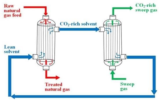
A new GLMC concept is found in Cai et al. [138], which proposed to carry out both the acid–gas absorption and solvent regeneration in a single step, i.e., in the same GLMC cross-flow modules. The aim is to save space in offshore processing plants. In this concept, the solvent flows on the shell-side, while two types of HFM are used in the module. CO2-rich NG flows in the microporous HFM at high-pressure (P = 50 bar), wherein CO2/H2S absorptions take place at the gas-liquid interface. Inside the GLMC module, there is also dense HFM, kept at low-pressure (P = 1 bar) so that the difference of pressure in relation to the solvent generates a stripping driving force which promotes solvent regeneration in the shell-side as CO2/H2S scape to the low-pressure HFM. Therefore, CO2/H2S absorption and solvent regeneration occur simultaneously in the GLMC module, theoretically resulting in better absorption efficiency as the solvent is kept with low acid-gas content while flowing through the GLMC module. The authors also suggest using baffles to improve mass transfer efficiency by increasing turbulence. Propylene carbonate was the physical solvent as it presents better CO2 solubility in comparison with water. The use of physical solvents is recommended as chemical solvents demand heat-intensive regeneration and require more space on offshore rigs. Indeed, it is easy to understand that this GLMC concept would never work with chemical solvents because chemical solvents would necessarily require a GLMC-absorber and a separate solvent regeneration step. The GLMC model considers isothermal mass transfers through the microporous HFMs, through the dense HFMs, and on the shell side. The authors assumed isothermal conditions and neglected gas head-losses. Despite the new concept, this work did not trigger analogous works by other authors since then.
An important and disruptive contribution comes from Ghasem et al. [60], as it was the first model to consider GLMC water vaporization and the respective heat effect, a phenomenon systematically ignored in the GLMC modeling literature, which prefers to assume isothermal GLMC modeling without water mass transfer, a fact that Ghasem et al. proved to be unrealistic. In [60], GLMC CO2 absorption from NG was performed using an aqueous-NaOH solvent. In comparison with previous works, a more complete GLMC model was developed (Table 7, Equations (47), (49)–(51), (54), (56), and (61)–(67)). Instead of considering isothermal GLMC and neglecting pressure drop, the model [60] considers mass, energy, and momentum balances. The work carried out experiments and results were compared with model predictions. Nonetheless, experiments were performed at atmospheric pressure with a raw NG composition of 10 mol% CO2 and 90 mol% CH4. Besides, in real NG processing, the high-pressure raw NG is water-saturated, so that water can transfer in both directions, a fact not considered in [60]. Moreover, real raw NG contains H2S and light hydrocarbons (C2+).
After the good work in [60], Ghasem et al. [139] published a badly written article with several typos, including the article title and the titles of some sections. CO2 absorption from NG was investigated experimentally and theoretically with a GLMC model comprising only material balances (Table 7, Equations (47), (48), (51), (53), and (56)). Aqueous potassium glycinate was compared with aqueous-amine solvents showing superior results, a questionable outcome. The article is a mess: the text creates confusion among MEA, DEA, and MDEA all the time. Thereby, it is impossible to be sure of which aqueous-amine solvents were investigated.
A complete GLMC thermodynamic model is found in de Medeiros et al. [33], which simulated an offshore high-pressure NG purification process for GLMC CO2 removal with aqueous-MEA-MDEA. The GLMC model comprises a new acid-gas, water, and alkanolamines equilibrium model (AGWA model) [140] capable of reproducing chemical absorption and desorption of CO2 (and H2S) in aqueous-amines, over a wide range of pressures, which was calibrated in terms of equilibrium constants with AGWA VLE data from the literature. The real species VLE is superimposed on the multi-reactive chemical equilibrium for the formation of fictitious species (non-ionic and non-volatile complexes), defining a reactive VLE or RVLE [
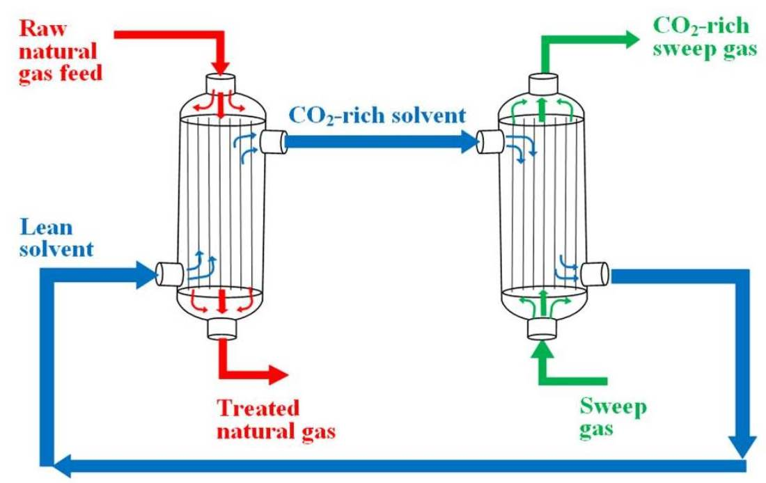
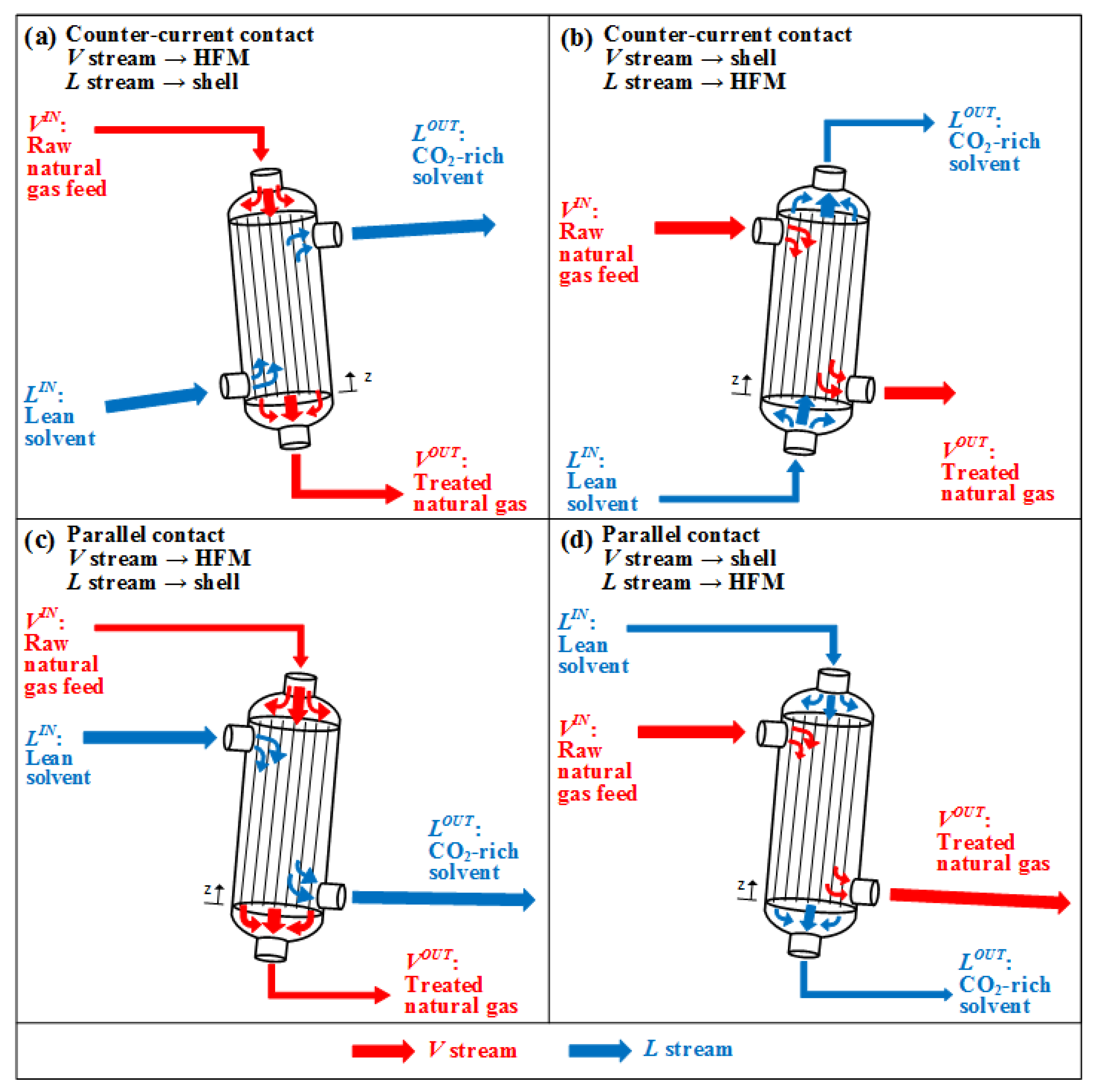
140]. The GLMC V and L flows are parallel and unidimensional (1D), assuming compressible two-phase plug-flow for V and L streams. The model also considered the mass transfer of CH4, H2O, and light hydrocarbons and was developed through rigorous mass, energy, and momentum balances for V and L streams, allowing heat and mass interfacial transfers, with shear and compressibility terms, and all properties of all phases rigorously calculated by the Peng–Robinson EOS (PR-EOS) and Soave–Redlich–Kwong EOS (SRK-EOS). This model was able to reproduce several interesting behaviors along the GLMC length as profiles of both streams, such as molar flowrates, species compositions, temperatures, pressures, fugacities, and CO2/CH4 selectivity [33]. Model equations are shown in Equations (1) to (7).
Trans-membrane fluxes of real species “k”:
N k f l u x = Π k * f ^ V k - f ^ L k
Real species EMWR (Equivalent Moles Without Reaction) mass balances for V and L streams:
d V k d z = S a N k f l u x
d L k d z = S a N k f l u x
where N k f l u x are trans-membrane fluxes of real species “k”; Π k are trans-membrane mass transfer coefficients of species “k”; f ^ V k and f ^ L k are the V and L fugacities of real species “k”; S a is the interfacial area per length; V k and L k are V molar flowrate and the L EMWR molar flowrate of real species “k.”
Momentum balances for V and L:
Γ T V * ( v V ) 2 d T V d z + Γ P V * ( v V ) 2 1 d P V d z + k n R S Γ V k * ( v V ) 2 d V k d z = ρ V g * s e n θ v V S V q S a + ψ V π D + S a S V
Γ T L * ( v L ) 2 d T L d z + Γ P L * ( v L ) 2 1 d P L d z + k n R S Γ L k * ( v L ) 2 d L k d z = ρ L g * s e n θ + v L S L q S a + v L v V S L q S a + ψ L S a S L
where D is the GLMC shell internal diameter, θ is GLMC inclination, g is the gravity acceleration, n R S is the number of real species, Γ T V and Γ T L are isobaric expansivity of V and L at RVLE, Γ P V and Γ P L are isothermal compressibility of V and L at RVLE, Γ V k and Γ L k are species “k” mol expansivity of V and L at RVLE, T V and T L are V and L temperatures, P V and P L are V and L absolute pressures, v V and v L are V and L flow velocities, ρ V and ρ L are V and L densities, S V and S L are sections of V and L flows, ψ V and ψ L are the shear stress on contact surfaces in V and L flows.
Energy balances for V and L:
ρ V C ¯ P V M V Γ T V ( v V ) 2 d T V d z + 1 + T V ρ V Γ T V Γ P V ( v V ) 2 d P V d z k n R S Γ V k * ( v V ) 2 d V k d z = v V S V q S a ρ V g * s e n θ + Ω E π D ρ V q V T a m b T V Ω I S a ρ V q V T V T L
ρ L C ¯ P L M L Γ T L ( v L ) 2 d T L d z + 1 + T L ρ L Γ T L Γ P L ( v L ) 2 d P L d z k n R S Γ L k * ( v L ) 2 d L k d z = v L S L q S a ρ L g * s e n θ + Ω I S a ρ L q L T V T L + S a ρ L q L k n R S N k f l u x E ¯ V k E ¯ L k E M W R
where C ¯ P V and C ¯ P L are V and L molar isobaric heat capacities, M V and M L are the V and L EMWR molar masses, q V and q L are V and L mass flowrates, q is the HFM mass flux, Ω E and Ω I are external and internal heat transfer coefficients, T a m b is the outside temperature, E ¯ V k and E ¯ L k E M W R are the PMPEMWR energies of “k” in V and L.
Faiz et al. [141] described a 2D GLMC model (Table 7, Equations (48), (50), (51), (53), and (55)–(57)) for H2S removal from high-pressure NG with water solvent. Model predictions agreed perfectly with the experimental data only at low pressures. At high pressures, agreement with experimental data only occurred when the “pseudo-wetting” condition (3%) (MPW) was assumed. The model ignores the transfer of other species, energy balances, and head losses.
Razavi et al. [79] modeled low-pressure GLMC CO2 removal from NG with an aqueous di-isopropanol amine (DIPA) solvent. The 2D GLMC model (Table 7, Equations (47), (48), (50)–(53), (55), and (56)) ignores thermal effects (isothermal GLMC), assumes ideal gas behavior, and considers only species mass balances without head-loss calculations.
Cai et al. [142] modeled crossflow GLMC for CO2 removal from NG. Experiments were performed and a CFD modeling was solved with ANSYS software. The model considers mass and momentum balances, without energy balance, in three-dimensional geometry. The study considered carbon capture from pure CO2 with water solvent at P = 1 atm and T = 298 K, which are distant values from real NG processing conditions.
Abdolahi-Mansoorkhani and Seddighi [80] investigated HFM improvements with the incorporation of montmorillonite nanoparticles for CO2 removal from CO2-CH4 mixtures (CO2 = 10 mol%, CH4 = 90 mol%) using aqueous-MEA, aqueous-PZ, aqueous-TEA, and aqueous-EDA solvents. A 2D finite element modeling in cylindrical coordinates predicted GLMC behavior (Table 7, Equations (47), (48), (50)–(53), and (55)–(60)). Despite the highly exothermic ChA with aqueous-amines, the model ignores energy balances, considering isothermal profiles without head-loss, ideal gas behavior, and VLE via Henry’s law. Besides, only CO2 is transferred.
Nakhjiri et al. [143] conducted experiments and developed a two-dimensional (2D) GLMC model (Table 7, Equations (47), (48), (50), (51), (53) and (55)–(57)) for prediction of CO2 removal from CO2-CH4 mixtures (CO2 = 30 mol%, CH4 = 70 mol%) with aqueous-MEA and aqueous-TEA. Predicted results were compared with experimental counterparts in both non-wetting and partial wetting (MPW) modes of operation. Model differential equations were solved with COMSOL software. This work did not unveil any noticeable novelty, as the isothermal low-pressure 2D model was developed with simplifications found in previously published works such as ideal gas behavior, Henry’s law for VLE, absence of H2S and H2O in raw NG, only CO2 transference, and no head-loss. Nakhjiri et al. [144] used almost the same equations (Table 7, Equations (47), (48), (50), (51), (53), and (55)–(60)) of [143], with the inclusion of aqueous-NaOH experiments, finding the following order of CO2 removal performances: aqueous-MEA > aqueous-NaOH > aqueous-TEA. Model predictions were compared with data from [95]. Nakhjiri and Heydarinasab [145] studied GLMC CO2 removal from a CO2-CH4 gas mixture (CO2 = 10 mol%, CH4 = 90 mol%) with aqueous ethylenediamine (EDA), aqueous 2-(1-piperazinyl)-ethylamine (PZEA) and aqueous potassium sarcosinate (PS) solvents using a model (Table 7, Equations (47), (48), (50)–(53) and (55)–(57)) similar to [143,144] models, considering non-wetting mode of operation. Model predictions were compared with data from [65] for validation, an awkward procedure since the experiments from [65] were conducted with pure water solvent. Posteriorly, Nakhjiri et al. [84] slightly improved their previous GLMC model [143] by considering simultaneous CO2/H2S removal with aqueous-K2CO3 solvent, including momentum balance equations (Table 7, Equations (47), (48), (50), (51), (53), (55)–(57) and (61)–(64)). However, all the remaining simplifications of [143,144,145] were kept.
Mesbah et al. [90] presented a theoretical study of GLMC CO2 removal from CO2-CH4 gas mixtures using an aqueous-K2CO3 solvent containing a 2-methylpiperazine (2MPZ) promoter. Despite considering a complex chemical reaction scheme of CO2 with aqueous-K2CO3-2MPZ, the 2D GLMC model (Table 7, Equations (47), (48), (50)–(53) and (55)–(57)) is simplified with the following assumptions: isothermal profiles, low-pressure, ideal gas behavior, Henry’s law VLE, and only CO2 is transferred. Awkwardly, the supposed model validation was performed with experimental data from [143], which involved only aqueous-MEA and aqueous-TEA solvents.
Fougerit et al. [146] performed an experimental and modeling study of GLMC CO2 removal from CO2-CH4-H2O gas mixtures covering a wide range of CO2 contents, namely: NG sweetening (CO2 = 5–10 mol%), post-combustion carbon capture (CO2 = 10–15 mol%), biogas upgrading (CO2 = 35–50 mol%). However, the authors ignored that each feed mixture needs different process conditions. Besides, the 1D mass transfer model is simplified: only CO2 transference is considered, isothermal GLMC, ideal gas behavior, and low-pressure (P = 5.0 bar).
The GLMC decarbonation of coal-bed methane, an NG abundant in China, was studied by Zhang et al. [147] with a 2D GLMC model (Table 7, Equations (48), (50), (51), (53) and (55)–(57)) considering aqueous-MEA, aqueous-DEA, aqueous-TEA and aqueous 1-(2-hydroxyethyl)pyrrolidine solvents. The GLMC model is also simplified: low-pressure, ideal gas behavior, and isothermal GLMC profiles were adopted for ChA with aqueous-amine solvents. Pan et al. [148] adopted the same GLMC model (Table 7, Equations (48), (50), (51), (53), (55), and (56)) for the simultaneous CO2/H2S removal from coal-bed methane using aqueous-K2CO3 with potassium lysinate (PL) solvent. The pressure influence in the range 1 bar–50 bar on CO2/H2S transfers was studied (still under ideal gas behavior).
Ghasem [149] experimentally studied GLMC CO2 absorption from CO2-CH4 mixtures (CO2 = 10 mol%, CH4 = 90 mol%) and also the CO2 stripping from the solvent. The solvent was 0.5 mol/L aqueous potassium glycinate in a closed loop with N2 as stripping gas. Experimental results were compared with predictions of a GLMC model, which is 2D axisymmetric and transient, considering CO2/CH4 transports in GLMC-absorber, and CO2/N2 transports in GLMC-stripper. The model is simplified: it considers low-pressure, ideal gas behavior, isothermal profiles, VLE via Henry’s law, and lacks energy balance and head-loss calculations. H2S and H2O are absent. Ghasem [150] investigated the influence of HFM bore size on the highly exothermic CO2 removal from NG with aqueous-MEA, considering VLE via Henry’s law. In comparison with [149], it was used a similar low-pressure 2D GLMC model at steady-state (Table 7, Equations (47), (48), (50), (51), (53), (55) and (56)).

GLMC Modeling with Professional Process Simulators for CO2 Removal from NG

Implementation of GLMC modeling for carbon capture from NG in professional process simulators is crucial for rigorous GLMC modeling due to more accurate thermodynamic properties estimation [128].
Among the few works implementing GLMC modeling in process simulators, there are studies on CO2 removal from other sorts of gas streams (e.g., biogas and syngas). Kerber and Repke [151] studied GLMC biogas purification, while Villeneuve et al. [152,153] studied carbon capture from post-combustion flue gas with GLMC implementation in Aspen Custom Modeler. Usman et al. [154] developed a GLMC model for pre-combustion CO2 capture in MATLAB. Posteriorly, Usman et al. [155] integrated the MATLAB code with the HYSYS process simulator through the Cape-Open simulation compiler.
There are just a few works on GLMC modeling in process simulators for CO2 removal from NG. Hoff et al. [156] conducted laboratory-scale experiments on CO2 removal from flue gas with aqueous-MEA and on high-pressure CO2 removal from NG with aqueous-MDEA. The authors developed a 2D diffusion-reaction model to predict experimental absorption rates and concentration/temperature GLMC profiles. The model considers mass, energy, and momentum balances, and VLE was modeled via Henry’s law with activity coefficients to account for liquid phase non-ideality. The model equations—shown in Equations (8) to (16)—were solved via MATLAB.
Gas mass balance equations:
d N k f l u x d z = v V R T V P V z + P V R T V v V z P V v V R T V 2 T V z = k N k f l u x A S I S A ε V
d v V d z = v V P V P V z + v V T V T V z R T V v V N k f l u x A S I S A ε V
d P V k d z = P V k v V v V z + P V k T V T V z R T V v V N k f l u x A S I S A ε V
k C ¯ P V , k N k f l u x T V z = Q
where R is the ideal gas constant, A S I S A is the specific GLMC inner surface area, ε V is the fraction of total area available to gas flow, C ¯ P V , k is the V molar isobaric heat capacity of species “k” and Q is the heat rate.
Trans-membrane mass flux of species “k”:
N k f l u x = P V k H k C L k , m R T V 1 k k , V + r o ln ( r o / r i ) D k , m e f f + X k k N k f l u x
D k , m e f f = D k ε τ
Q = 1 1 Ω V + 1 Ω m T V T L , m
where P V k is the partial pressure of “k,” H k is Henry’s law constant of “k,” C L k , m is the concentration of “k” at the liquid–membrane interface, k k , V is the gas film mass transfer coefficient of “k,” r i and r o are the internal and external HFM radiuses, D k , m e f f is the effective membrane diffusivity of “k,” D k is the molecular diffusivity of “k,” ε is membrane porosity, τ is membrane tortuosity, Ω V is V heat transfer coefficient, Ω m is the HFM heat transfer coefficient and T L , m is the temperature at liquid-membrane interface.
Transport model for the liquid phase based upon mass and energy conservation:
2 v L 1 r r i 2 C L k z = D k 1 r C L k r + 2 C L k r 2 + D k r C L k r + R k
2 v L 1 r r i 2 C ¯ P L ρ L T L z = λ L 1 r r r T L r + R k Δ H r
where C L k is L molar concentration of “k,” R k is the chemical reaction rate in terms of “k,” C ¯ P L is the L molar isobaric heat capacity, λ L is L thermal conductivity, and Δ H r is the enthalpy of reaction.
Posteriorly, the model of Hoff et al. [156] was improved for utilization in process simulators, including new thermodynamic models for aqueous-MEA and aqueous-MDEA/PZ, and solvent flow modeling inside HFM or in shell-side, besides improvements for gas and solvent head-loss calculation. In Hoff and Svendsen [157], the GLMC model comprises an RVLE CO2-water-amines system based on the Deshmukh–Mather approach [158], employing a modified Debye–Hückel model similar to Kuranov et al. [159]. The gas phase was modeled with PR-EOS and the trans-membrane fluxes were modified as shown in Equations (17) to (19).
N k f l u x = f ^ V k - f ^ L k Z R T V 1 k k , V + 1 k k , m + H E k k , L + X k k N k f l u x
k m = ε D p τ r i ln r o / r i
D p = 1 1 X L 1 D m + 1 D K n + X L 1 D m , L
where Z , k k , V , k m , k k , L , E , D p , D m , D K n , D m , L , X L are respectively, compressibility factor, gas film, membrane and liquid film mass transfer coefficients of “k,” enhancement factor, combined diffusivity, membrane diffusivity, Knudsen diffusivity, diffusivity of membrane at liquid phase and partial liquid penetration, respectively.
In Hoff and Svendsen [157], the following gas treatments were simulated: (i) low-pressure post-combustion carbon capture from offshore gas-turbines flue-gas to attain 90% capture with 30 w/w% aqueous-MEA in GLMC cross-flow modules installed in the process simulator SINTEF/NTNU CO2SIM; (ii) high-pressure (P = 70 bar) offshore sweetening of NG (CO2 = 10 mol%) to CO2 = 2.5 mol% using 30 w/w% aqueous-MDEA in GLMC parallel-flow modules installed in the process simulator Protreat; (iii) high-pressure (P = 70 bar) offshore sweetening of NG (CO2 = 10 mol%) to LNG specification of CO2 = 50 ppm-mol using 30 w/w% aqueous-MDEA with 5 w/w% PZ in GLMC parallel-flow modules installed in the process simulator Protreat. In comparison with packing columns, total equipment volume can be reduced to 25% using GLMC with liquid on the shell side. With liquid flowing inside HFM, the advantage reduces significantly. Authors highlighted that GLMC may significantly improve offshore CO2 capture from gas–turbine flue-gas and for NG sweetening but pointed out the doubtful advantage of GLMC for post-combustion carbon capture due to a large number of required GLMC modules and high head-losses of V and L streams.
Quek et al. [160] developed a predictive GLMC model for high-pressure NG sweetening. A temperature correction was calculated for the adiabatic GLMC to account for the ChA thermal effects. Model equations were implemented in gPROMS modeling language using a second-order centered finite difference scheme to discretize the differential equations. Model results attained good comparison with lab-scale experiments of CO2 absorption from CH4-CO2 and N2-CO2 mixtures at P = 11 bar and from pilot-scale experiments on NG sweetening at P = 54 bar, both using 39 w/w% aqueous-MDEA with 5 w/w% PZ.
Quek et al. [161] indicated limitations of their work [160] since it fails to describe the gradual increase in temperature through the equipment, besides not considering solvent evaporation. Thus, an improvement of their GLMC model was carried out in [161] via combining 1D and 2D mass balance equations to include MPW. Real gas behavior is implemented via PR-EOS. The GLMC model is shown in Equations (20) to (26).
Gas mass balance:
v ¯ V z C ¯ V C O 2 z z = 2 ε D C O 2 , V τ r i 1 Z R T V P V C V C O 2 r i + , z r
v ¯ V z z = 2 ε D C O 2 , V τ r i Z R T V P V C V C O 2 r i + , z r
Membrane-dry mass balance:
0 = 2 C C O 2 r , z r 2 + 1 r C C O 2 r , z r
Membrane-wet mass balance:
0 = ε τ D k , L 2 C L k r , z r 2 + 1 r C L k r , z r + R k C L k r , z ,   k CO 2 , solvent
Liquid mass balance:
v L r C L k r , z z = D k , L 2 C L k r , z r 2 + 1 r C L k r , z r + 2 C L k r , z z 2 + R k C L k r , z ,   k CO 2 , solvent
v L r = 2 v ¯ L r s h e l l 2 r o 2 r s h e l l 2 r o 2 + 2 r s h e l l 2 ln r o r s h e l l 4 r o 2 r s h e l l 2 r o 4 3 r s h e l l 4 4 r s h e l l 4 ln r o r s h e l l
v ¯ L = F L N H F π r s h e l l 2 1 ϕ
where v ¯ V and v ¯ L are V and L average velocities, C ¯ V C O 2 is the average V concentration of CO2, D C O 2 , V is V CO2 diffusivity, D k , L is L diffusivity of “k,” r s h e l l is the outer radius of the virtual cylindrical domain around each HFM, r 1 + is the gas-membrane interface at the pore-side, F L is L volumetric flowrate, N H F is the number of HFM within GLMC module and φ is the fiber volume fraction (packing-ratio).
To predict solvent evaporation in counter-current GLMC [161], the authors assumed a water-saturated gas at the GLMC outlet and used Raoult’s law to calculate H2O content. However, there is some impertinency in this assumption, as the two premises for Raoult’s law are: (i) ideal gas vapor phase at low-pressure; (ii) ideal solution liquid phase with chemically similar species. As the GLMC has a gas phase at high pressure in VLE with a non-ideal solution with high ionic interaction between species, it would be much more adequate to use an equation-of-state for vapor fugacities, besides an excess Gibbs free energy local composition model for aqueous electrolyte systems. At the end of the article, the authors admitted that Raoult’s law is questionable. Moreover, an energy balance was performed [161], considering the heat losses of solvent evaporation. As there is an inaccuracy in solvent loss prediction, this step is probably also inaccurate. Moreover, Henry’s law was employed to calculate liquid phase methane, ethane, and propane concentrations. These steps are shown in Equations (27) to (31).
V composition:
Y k out = X k in P k sat P V ,   k H 2 O , solvent
Rate of solvent loss:
q V k = Y k out M V k v ¯ V 0 N HF π r 1 2 P V ZRT V = X k out M V k v ¯ V 0 N HF π r 1 2 P k sat ZRT V ,   k H 2 O , solvent
Energy balance:
F L ρ L C P L d T L z d z = N H F π r 1 2 v ¯ V z C ¯ V C O 2 z z Δ H r
L light hydrocarbons concentrations:
C L k out = Y k in P V H k ,   k CH 4 , C 2 H 6 , C 3 H 8
Light hydrocarbons loss rate:
q L k out = C L k out M L k F L ,   k CH 4 , C 2 H 6 , C 3 H 8
where Y k o u t is V outlet mol fraction of “k,” X k o u t and X k i n are L outlet/inlet mol fraction of “k,” P k s a t is the saturation pressure of “k,” q V k is V mass flowrate of “k,” M V k is V molar mass of “k,” v ¯ V is V average velocity and C P L is L mass isobaric heat capacity.
Besides ignoring solvent head-loss [161], the authors tried to convince us that gas head-loss can be safely neglected. On the other hand, several researchers, including Hoff and Svendsen [157], proved exactly the opposite. The model was solved with gPROMS modeling language. Gas feed compositions were 20–24 mol% CO2 in a N2-CO2 mixture (P = 54 bar, T = 293 K) in lab experiments and 5–18 mol% CO2 NG (P = 54 bar, T = 298 K) in pilot runs. Solvent was 37 w/w% aqueous-MDEA with 6 w/w% PZ (P = 54.30 bar, T = 310–313 K) in lab experiments and 39 w/w% aqueous-MDEA with 5 w/w% PZ (T = 303–308 K) in pilot runs.
Quek et al. [162] installed the GLMC model from [161] in the process simulator gPROMS to perform the techno-economic assessment of the complete process for high-pressure NG sweetening and low-pressure regeneration in a closed-loop. Simulations predicted CO2 absorption and light hydrocarbons losses, solvent evaporation, besides process energy consumption. Results were compared with data from a pilot plant in Malaysia with reasonable agreement. Raw gas composition was CO2 = 5 mol%, CH4 = 85 mol%, C2H6 = 7 mol%, C3H8 = 3 mol% at P = 54 bar, T = 298 K, and the fresh solvent was 39 w/w% aqueous-MDEA with 5 w/w% PZ (P = 54.3 bar, T = 303–308 K). Two solvent regenerations were considered: regeneration in stripping columns or semi-regeneration in low-pressure flash separators. Posteriorly, the design and scale-up of a commercial-scale GLMC was conducted with a semi-lean solvent at raw gas composition CO2 = 24 mol%, CH4 = 73 mol%, C2H6 = 2 mol%, C3H8 = 1 mol% (P = 54 bar, T = 298 K), while the semi-lean solvent was 39 w/w% aqueous-MDEA with 5 w/w% PZ (P = 54.3 bar, T = 318 K). CO2 content was abated from 24 mol% to 6.5 mol%, which the authors considered excellent as they recommended the semi-lean regeneration with low-pressure flash to reduce energy consumption. However, it is widely known that the CO2 target for NG sweetening usually ranges from 2 to 3 mol% [14]; thereby, employing stripping columns for complete solvent regeneration is more adequate in this case.
Da Cunha et al. [128] performed a technical evaluation of GLMC CO2 removal from CO2-rich NG using 30 w/w% aqueous-MEA through process simulations in Aspen HYSYS V8.8. The authors developed a GLMC model, with the driving force for CO2 transfer predicted with CO2 V and L fugacity differences, rigorously calculated with thermodynamic resources of Aspen HYSYS V8.8 provided by the Acid-Gas package [163] (based on Electrolyte-NRTL model) for liquid phase properties and PR-EOS for vapor properties [164]. GLMC model equations consist of a non-linear algebraic system in Equations (32) to (34) solved by Newton-Raphson Method.
N k = Π k A f ^ V C O 2 i n - f ^ L C O 2 o u t - f ^ V C O 2 o u t - f ^ L C O 2 i n ln f ^ V C O 2 i n - f ^ L C O 2 o u t - ln f ^ V C O 2 o u t - f ^ L C O 2 i n
N k = L o u t X C O 2 o u t L i n X C O 2 i n
N k = V i n Y C O 2 i n V o u t Y C O 2 o u t
where N k is the trans-membrane transfer rate of component “k,” Π k is the trans-membrane mass transfer coefficient of “k,” A is the transfer area of the GLMC battery, f ^ V C O 2 and f ^ L C O 2 are V and L CO2 fugacities, Y C O 2 and X C O 2 are V and L CO2 molar fractions, and V and L are molar flowrates.
To perform process simulations in HYSYS, the authors created a GLMC HYSYS Unit Operation Extension (GLMC-UOE), in a similar procedure to Arinelli et al. [165] for MP unit operation. GLMC-UOE was programmed in Visual Basic 6.0, which contains an HYSYS Type Library with commands to access HYSYS directly. After programming and compiling the code, an external DLL file was generated, which was installed through an EDF file as an available unit operation in the HYSYS palette usable in HYSYS flowsheets. The EDF file was programmed with the Aspen HYSYS Extension View Editor and also provided the GLMC-UOE property windows, where an HYSYS user interface is filled by the user with all the necessary simulation information. GLMC model equations were programmed to be solved by the Newton–Raphson Method.
GLMC-UOE [128] is worthy of note because its present version already represents a new unit operation GLMC, which is implemented within an up-to-date professional simulation environment using full thermodynamics to calculate fluid properties and fugacities of real liquid and gas phases. Moreover, GLMC-UOE can be integrated into processing flowsheets comprising several other unit operations offered in the HYSYS palette, eventually constituting very complex process flowsheets.

4.2. GLMC Modeling for CO2 Stripping from the Solvent

Complete GLMC models for low-pressure CO2 stripping from the solvent require the same framework of GLMC for CO2 removal from NG, as described in the first paragraph of Section 4.1.
Some GLMC models were developed for CO2 stripping from physical solvents. Mehdipourghazi et al. [166] investigated CO2 stripping from the water via PVDF-HFM GLMC. The 2D model (Table 7, Equations (48), (50)–(53), (55), and (56)) only considers isothermal CO2 transfer. Lee et al. [167] also studied vacuum-driven GLMC CO2 stripping from water through experiments and using a 1D GLMC model (Table 6, Equations (35)–(38)) to assess liquid flowrate, vacuum pressure, and pH. Bahlake et al. [168] investigated GLMC CO2/H2S simultaneous stripping from the water via a 3D modeling approach whose differential equations were solved with COMSOL software. Sohaib et al. [69] investigated two ionic liquids for post-combustion carbon capture via GLMC-absorber coupled to GLMC-stripper. A 2D dynamic model (Table 7, Equations (48), (50)–(53), (55), and (56))was implemented based on low-pressure and low-temperature mass transfer equations. Vadillo et al. [169] developed a 1D-2D GLMC model (Table 7, Equation (55), Table 8, Equation (68)) for vacuum-driven regeneration of the ionic–liquid 1-ethyl-3-methylimidazolium acetate [emin][Ac] solvent considering isothermal conditions. The best operating conditions were achieved at P = 0.4 bar and T = 310 K.
The literature has an evident interest in GLMC CO2 stripping from aqueous-MEA. Ghadiri et al. [170] used pure N2 for CO2 stripping in a GLMC modeling study. The 2D model (Table 7, Equations (48), (53) and (55)–(57)) assumed isothermal and steady-state conditions, only CO2 transference, and VLE via Henry’s law. CO2 mass transfer predictions were compared with experimental data from [113], with reasonable agreement. To remove CO2 from 20 w/w% aqueous-MEA at T = 353 K, Wang et al. [171] used vacuum-driven stripping with steam as a stripping agent on the shell side at P = 20 kPa. The 1D-2D model (Table 7, Equation (55), Table 8, Equation (68)) is based on a system of steady-state continuity equations for each species with simultaneous diffusion and chemical reaction, considering isothermal operation and VLE via Henry’s law. Mohammed et al. [172] developed a 2D GLMC model (Table 7, Equations (48), (50)–(53), (55), and (56)) to investigate the effect of SiO2 nanoparticles on CO2 stripping from aqueous-MEA. Authors considered isothermal GLMC and VLE via Henry’s law. No energy balances or head-loss calculations were performed.
The following works were conducted in the context of post-combustion carbon capture. They are considered in the present review as low-pressure GLMC CO2 stripping from the solvent is conducted similarly for both GLMC processes for carbon capture from NG and flue gas. Scholes [173] used a simple model and a 1D rigorous model (Table 6, Equations (35)–(37), (39), (40), (42), and (44)–(46)) with mass/energy balances and pressure drop calculation to study vacuum-driven CO2 stripping from aqueous-MEA 30 w/w%, using steam as stripping-gas. The best stripping temperature was found between 90 °C and 105 °C. Above this temperature range, the solvent starts vaporizing, and below this range, the mass transfer driving force is drastically reduced. Scholes highlighted the trade-off between the reduction of stripping heat requirement against the vacuum pump power requirement. Zaidiza et al. [174] developed a GLMC model for post-combustion CO2 absorption with aqueous-MEA solvent and for the respective CO2 stripping. The 1D adiabatic model (Table 6, Equations (35)–(39) and (41)–(46)) considers the bidirectional mass transfer of all species (CO2, H2O, MEA); energy balances; and head-loss calculations via Hagen-Poiseuille equation for the HFM stream and via Happel equation [175] for the shell-side. Model equations were presented with dimensional problems and inverted signs (e.g., Pa.s−1 was the viscosity unit instead of Pa.s). Model assumptions include steady-state, ideal gas behavior, and VLE via Henry’s law. Water condensation/evaporation was considered at the liquid-membrane interface. The authors emphasize that GLMC-stripper needs HFM resistant to high temperatures (≈120 °C). Also, since water can be transferred in both directions, capillary condensation can occur, which would negatively influence mass transfer performance similarly to MPW.

4.3. GLMC Models Not Related to Process Simulators

The main GLMC models not related to processing simulators are presented in Table 6 for 1D models, Table 7 for 2D models, and Table 8 for 1D-2D models. These models were already discussed in Section 4.1 and are detailed here for completeness. They usually lack thermodynamic frameworks and present several simplifications, such as isothermal GLMC and ideal gas behavior. These tables list equations and modeling strategies adopted, showing that several researchers used the same equations. Table 9 presents the used software for the numerical solution of GLMC equations.

5. Concluding Remarks and Future Prospects

Aqueous-amine solvents are the most studied in high-pressure NG sweetening and in solvent regeneration with GLMC. Regarding physical solvents, the increasing interest in ionic liquids is highlighted.
Both experimental and modeling GLMC works on carbon capture from CO2-rich NG must consider all the real offshore operating conditions: (i) high-pressure operation; (ii) mass transfer of all species, including CO2, H2S, CH4, H2O, and other light hydrocarbons; (iii) thermal effects, with outlet temperatures assessment; (iv) head-losses of both phases.
Several experimental works were restricted to CO2 mass transfer at low pressures. The most useful experimental GLMC works so far investigated high-pressure simultaneous CO2/H2S removal from gas mixtures containing CH4, as in [100,101]. Experimental works were usually focused on inlet conditions optimizations to enhance CO2 mass transfer. To our knowledge, there are no works in the literature providing data on water mass transfer. Pressure drop is frequently neglected in the bench scale but should be investigated at least in the pilot scale. Data of light hydrocarbons (C2+) mass transfer are also scarce. Therefore, future experimental works should perform complete outlet conditions assessments, providing a complete understanding of GLMC behavior.
The development of GLMC models not related to processing simulators is a complex work and imposes an additional task: the supply of a thermodynamic framework for correct RVLE calculation and thermodynamic and transport properties prediction. This was done in de Medeiros et al. [33], in which a full thermodynamic framework was provided for simulation of CO2 removal from high-pressure NG with a 1D GLMC model considering rigorous multicomponent mass, energy, and momentum balances.
Among the scarce GLMC models that apply at least mass, energy, and momentum balances, Ghasem et al. [60] provided a 2D model for CO2 absorption from NG, while Scholes [173] and Zaidiza et al. [174] provided 1D models for CO2 stripping from the solvent. On the other hand, it can be seen in Table 6, Table 7, Table 8 and Table 9 that several 2D models are performing CO2 mass transfer with simplifications such as isothermal condition, ideal gas behavior, and zero pressure drop, using COMSOL or CFD to solve GLMC equations via finite elements. It can be concluded that these models are simplified and cannot reproduce industrial GLMC behavior for NG conditioning with accuracy. Typical examples are [80,150], which proposed 2D models for isothermal CO2 absorption from NG with aqueous-amine solvents.
GLMC modeling and its implementation in up-to-date process simulators are of great importance to enable industrial-scale technical-economic assessment. In [156,157], mass, energy, and momentum balances were considered, but the multicomponent mass transfer was not. In [161,162], despite considering energy balance and multicomponent mass transfer, the thermodynamic framework is inadequate, and there is no pressure drop calculation. Da Cunha et al. [128] developed a GLMC-UOE to access HYSYS full thermodynamics. Just CO2 mass transfer was considered, and the model lacks energy and momentum balances. The point here is that to obtain a complete GLMC model to be installed in process simulators, the model must gather all the positive aspects of [128,156,157,161,162].
Moreover, it is worthwhile to think of distributed parameters models as in [33] for GLMC-absorber and [174] for GLMC-stripper. The work of Lock et al. [176] created an MP unit operation extension (MP-UOE) installed in Aspen HYSYS with the same method as da Cunha et al. [128] for GLMC-UOE. To construct the MP-UOE distributed model [176], the succession of states approach was employed, in which the equipment is divided into many finite cells in the axial direction. In the same way, it would be interesting to develop a GLMC complete distributed model to be installed in Aspen HYSYS as GLMC-UOE or in other available process simulators.

Author Contributions

Conceptualization J.L.d.M.; methodology, J.L.d.M. and O.d.Q.F.A.; formal analysis, G.P.d.C., J.L.d.M., and O.d.Q.F.A.; investigation, G.P.d.C. and J.L.d.M.; data curation, G.P.d.C.; writing—original draft preparation, G.P.d.C. and J.L.d.M.; visualization, G.P.d.C.; writing—review and editing, J.L.d.M. and O.d.Q.F.A.; supervision, J.L.d.M. and O.d.Q.F.A.; project administration, J.L.d.M. and O.d.Q.F.A. All authors have read and agreed to the published version of the manuscript.

Funding

J.L.d.M. and O.d.Q.F.A. acknowledge financial support from CNPq-Brazil (313861/2020-0 and 312328/2021-4).

Institutional Review Board Statement

Not applicable.

Informed Consent Statement

Not applicable.

Data Availability Statement

Not applicable.

Conflicts of Interest

The authors declare no conflict of interest.

Abbreviations

1DOne-Dimensional
2DTwo-Dimensional
AGWAAcid-Gas Water Alkanolamines
CCSCarbon Capture and Storage
CCUSCarbon Capture Utilization and Storage
CFDComputational Fluid Dynamics
ChAChemical-Absorption
DEPGDimethyl Ether of Polyethylene Glycol
DLLDynamic-Link Library
EDFExtension Definition File
EMWREquivalent Moles Without Reaction
e-NRTLElectrolyte Non-Random Two Liquid
EGREnhanced Gas Recovery
EOREnhanced Oil Recovery
GHGGreenhouse Gas
GLMCGas-Liquid Membrane Contactor
GLMC-UOEGas-Liquid Membrane Contactor HYSYS Unit Operation Extension
HFMHollow-Fiber Membrane
MDEAMethyldiethanolamine
MEAMonoethanolamine
MMNm3/dMillions of Normal Cubic Meters per Day
MPMembrane Permeation
MP-UOEMP-UOE Membrane Permeation Unit Operation Extension
MPWMembrane Pore Wetting
NGNatural Gas
NRMNewton-Raphson Method
ODEOrdinary Differential Equations
PC-SAFTPerturbed Chain Statistical Association Fluid Theory Equation-of-State
PFDProcess Flow Diagram
PMPPartial Molar Property
PPPolypropylene
PPOPolyphenylene Oxide
PRPeng-Robinson Equation-of-State
PSAPressure Swing Adsorption
RVLEReactive Vapor-Liquid Equilibrium
UOEUnit Operation Extension
VLEVapor-Liquid Equilibrium
WDPAWater Dew-Point Adjustment

Nomenclature

A S I S A Specific inner surface area of GLMC module (m2/m3)
A E ,   A I External/internal convective heat exchange areas (m2)
A C S H F Cross-section area inside HFM (m2)
A C S S Cross-section area within GLMC shell and outside HFM (m2)
a e x t External specific interfacial area (-)
a int Internal specific interfacial area (-)
a m Specific membrane area (-)
A Mass transfer area of the GLMC battery (m2)
C V k ,   C L k Molar concentration of “k” in V stream and L stream (mol/m3)
C k , i Molar concentration of “k” inside HFM (mol/m3)
C k , m Molar concentration of “k” inside membrane pores (mol/m3)
C k , mL Molar concentration of “k” inside the liquid-filled part of HFM pores (mol/m3)
C k , mV Molar concentration of “k” inside the gas-filled part of HFM pores (mol/m3)
C k , o Molar concentration of “k” in the shell side (mol/m3)
C L j Molar concentration of “j” in L (mol/m3)
C L k * Molar concentration of “k” in L at equilibrium (mol/m3)
C L k , m Concentration of “k” at liquid-membrane interface (mol/m3)
C ¯ V C O 2 Average V concentration of CO2 (mol/m3)
C ¯ P V ,   C ¯ P L V and L molar isobaric heat capacities (kJ/(kmol.K))
C ¯ P V , k V partial molar isobaric heat capacities of species “k” (kJ/(kmol.K))
C P i Mass isobaric heat capacities of stream inside HFM (J/(kg.K))
C P o Mass isobaric heat capacities in the shell side (J/(kg.K))
C P V ,   C P L V and L mass isobaric heat capacities (J/(kg.K))
D GLMC shell internal diameter (m)
D C O 2 , V V CO2 diffusivity (m2/s)
D k , m e f f Effective membrane diffusivity of “k” (m2/s)
D k Molecular diffusivity of “k” (m2/s)
D k , L L diffusivity of “k” (m2/s)
D K n Knudsen diffusivity (m2/s)
D m Membrane diffusivity (m2/s)
D m , L Diffusivity of membrane at liquid phase (m2/s)
D p Combined diffusivity (m2/s)
D k , i Diffusivity of “k” inside HFM (mol/m3)
D k , m Diffusivity of “k” inside membrane pores (mol/m3)
D k , mL Diffusivity of “k” inside the liquid-filled part of HFM pores (mol/m3)
D k , mV Diffusivity of “k” inside the gas-filled part of HFM pores (mol/m3)
D k , o Diffusivity of “k” in the shell-side (mol/m3)
d i ,   d o Internal/external HFM diameter (m)
E Enhancement factor
E ¯ V k ,   E ¯ L k E M W R PMPEMWR energies of “k” in V and L (kJ/mol)
F L L volumetric flowrate (m3/s)
f ¯ ^ L k in ,   f ¯ ^ L k out Vector of L inlet/outlet fugacities of “k” (bar)
f ^ V K , f ^ L K V and L fugacities of real species “k” (bar)
g Gravity acceleration (9.81 m/s2)
Δ H k , a b s / e v a p Enthalpy of absorption or vaporization (kJ/kmol);
Δ H r Enthalpy of reaction (kJ/kmol)
k k , V Gas film mass transfer coefficient of “k” (mol/(m2.s.kPa))
k k , L Liquid film mass transfer coefficient of “k” (mol/(m2.s.kPa))
k k , m Membrane mass transfer coefficient of “k” (mol/(m2.s.kPa))
k k , o v Overall mass transfer coefficient of “k” (m/s)
K k o z Kozeny factor (m−2)
k r Kinetic constant for “k” (m/s)
L k f l u x L stream molar flux of “k” (mol/s)
L k L molar flowrate of “k” (mol/s)
M V ,   M L V and L EMWR molar masses (kg/mol)
M V k ,   M L k V and L molar masses of “k” (kg/mol)
N H F Number of HFM within GLMC module
N k f l u x Trans-membrane fluxes of real species “k” (mol/(s.m2))
N k Trans-membrane mass transfer rates of “k” (mol/s)
N M Number of GLMC modules
n R S Number of real species
P k s a t Saturation pressure of “k” (bar)
P i Pressure inside HFM (bar)
P o Pressure in the shell-side (bar)
P V ,   P L V and L absolute pressures (bar)
P V k Partial pressure of “k” (bar)
q V ,   q L ,   q V and L mass flowrates (kg/s); HFM mass flux (kg/(s.m2))
q V k ,   q L k V and L mass flowrates of “k” (kg/s)
Q f l u x Heat flux (W/m2)
Q Heat rate (kJ/h)
R Ideal gas constant (8.314 J/(mol.K))
R k Chemical reaction rate in terms of “k” (mol/(m3.s))
R k , m L Chemical reaction rate of “k” inside the liquid-filled part of HFM pores (mol/(m3.s))
r GLMC radial position (m)
r i ,   r o Internal/external HFM radius (m)
r s h e l l Outer radius of virtual cylindrical domain around each HFM (effective radius of shell-side) (m)
r i + Gas-membrane interface at the pore-side (m)
S a = N H F π d o Interfacial area per length (m)
S V ,   S L Sections of V and L flows (m2)
T a m b Outside temperature (K)
T ,   T V ,   T L Temperature, V and L temperatures (K)
T L , m Temperature at liquid–membrane interface (K)
T i HFM inside temperature (K)
T m HFM temperature (K)
T o Shell-side temperature (K)
UOverall heat transfer coefficient (kJ/(h.m2.K)) or (W/(m2.K))
V k f l u x V molar flow (flux) of “k” (mol/s)
V k V molar flowrate of “k” (mol/s)
v i ,   v o Interstitial velocity of the stream at internal/external surface of HFM (m/s)
v V ,   v L V and L flow velocities (m/s)
v ¯ V ,   v ¯ L V and L flow average velocities (m/s)
v r , i Velocity in radial direction inside HFM (m/s)
v r , o Velocity in radial direction in the shell-side (m/s)
v ¯ z , i Average velocity in axial direction inside HFM (m/s)
v z , i Velocity in axial direction inside HFM (m/s)
v ¯ z , o Average velocity in axial direction in the shell-side (m/s)
v z , o Velocity in axial direction in the shell-side (m/s)
X L Partial liquid penetration
Y k ,   X k V and L mol fractions of “k”
Z Compressibility factor
zGLMC axial position (m)
Greek Symbols
Γ P V ,   Γ P L Isothermal compressibility of V and L at RVLE (kg/(Pa.m3))
Γ T V ,   Γ T L Isobaric expansivity of V and L at RVLE (kg/(K.m3))
Γ V k ,   Γ L k Species “k” mol expansivity of V and L at RVLE ((kg.s)/(mol.m3))
ε Membrane porosity
ε V Fraction of total area available for gas flow
H k Henry’s law constant of “k” ((kPa.m3)/mol)
θ GLMC inclination (rad)
λ V ,   λ L V and L thermal conductivities (W/(m.K))
μ i Dynamic viscosity of the predominant phase inside HFM (Pa.s)
μ o Dynamic viscosity of the predominant phase in shell-side (Pa.s)
φ Fiber volume fraction (packing ratio) (-)
Π k Trans-membrane mass transfer coefficient of “k” (mol/(s.bar.m2))
ρ V ,   ρ L V and L densities (kg/m3)
ρ i Density inside HFM (kg/m3)
ρ o Density in the shell-side (kg/m3)
τ Membrane tortuosity
ψ V ,   ψ L Shear stress on contact surfaces in V and L flows (Pa)
Ω E ,   Ω I External/internal heat transfer coefficients (kJ/(h.m2.K)) or (W/(m2.K))
Ω V ,   Ω L V and L heat transfer coefficient (kJ/(h.m2.K)) or (W/(m2.K))
Ω m HFM heat transfer coefficient (kJ/(h.m2.K)) or (W/(m2.K))
Ω i Heat transfer coefficient inside HFM (W/(m2.K))
Ω o Heat transfer coefficient in the shell-side (W/(m2.K))
Superscripts
outat outlet
inat inlet

References

  1. Sedej, O.; Mbonimpa, E. CFD Modeling of a Lab-Scale Microwave Plasma Reactor for Waste-to-Energy Applications: A Review. Gases 2021, 1, 11. [Google Scholar] [CrossRef]
  2. Günther, M.; Nissen, V. Effects of the Henry Hub Price on U.S. LNG exports and on gas flows in Western Europe. Gases 2021, 1, 6. [Google Scholar] [CrossRef]
  3. Chandrasekar, A.; Syron, E. Evaluation of Heat Decarbonation Strategies and Their Impact on the Irish Gas Network. Gases 2021, 1, 14. [Google Scholar] [CrossRef]
  4. Shahid, M.Z.; Maulud, A.S.; Bustam, M.A.; Suleman, H.; Halim, H.N.A.; Shariff, A.M. Packed column modelling and experimental evaluation for CO2 absorption using MDEA solution at high pressure and high CO2 concentrations. J. Nat. Gas Sci. Eng. 2021, 88, 103829. [Google Scholar] [CrossRef]
  5. Mokhatab, S.; Poe, W.A.; Mak, J.Y. Handbook of Natural Gas Transmission and Processing—Principles and Practices, 3rd ed.; Gulf Professional Publishing-Elsevier: Waltham, MA, USA, 2015; pp. 2–125. [Google Scholar]
  6. Araújo, O.Q.F.; Reis, A.C.; de Medeiros, J.L.; do Nascimento, J.F.; Grava, W.M.; Musse, A.P.S. Comparative analysis of separation technologies for processing carbon dioxide rich natural gas in ultra-deepwater oil fields. J. Clean. Prod. 2017, 155, 12–22. [Google Scholar] [CrossRef]
  7. Rakhiemah, A.N.; Xu, Y. Economic viability of full-chain CCUS-EOR in Indonesia. Resour. Conserv. Recyl. 2022, 179, 106069. [Google Scholar] [CrossRef]
  8. Amarasinghe, W.; Farzaneh, S.; Fjelde, I.; Sohrabi, M.; Guo, Y. A visual investigation of CO2 convective mixing in water and oil at the pore scale using a micromodel apparatus at reservoir conditions. Gases 2021, 1, 5. [Google Scholar] [CrossRef]
  9. Liu, S.; Yuan, L.; Liu, W.; Zhao, C.; Zhang, Y.; Song, Y. Study on the influence of various factors on dispersion during enhance natural gas recovery with CO2 sequestration in depleted gas reservoir. J. Nat. Gas Sci. Eng. 2022, 103, 104644. [Google Scholar] [CrossRef]
  10. Egging-Bratseth, R. A techno-economic perspective on natural gas and its value chain. Gases 2021, 1, 1. [Google Scholar] [CrossRef]
  11. Shi, M.; Xiong, W.; Zhang, X.; Ji, J.; Hu, X.; Tu, Z.; Wu, Y. Highly efficient and selective H2S capture by task-specific deep eutectic solvents through chemical dual-site absorption. Sep. Purif. Technol. 2022, 283, 120167. [Google Scholar] [CrossRef]
  12. Trueba, L., Jr.; Gaston, T.; Brackin, J.; Miller, J.; You, B.H. Effective strategies to reduce triethylene glycol consumption in natural gas processing plants. Case Stud. Chem. Environ. Eng. 2022, 5, 100196. [Google Scholar] [CrossRef]
  13. Shamsi, M.; Farokhi, S.; Pourghafari, M.; Bayat, A. Tuning the natural gas dew poInt. by Joule-Thomson and Mechanical Refrigeration processes: A comparative energy and exergy analysis. J. Petrol. Sci. Eng. 2022, 212, 110270. [Google Scholar] [CrossRef]
  14. Ecker, A.M.; Klein, H.; Peschel, A. Systematic and efficient optimization-based design of a process for CO2 removal from natural gas. Chem. Eng. J. 2022, 445, 136178. [Google Scholar] [CrossRef]
  15. Abd, A.A.; Othman, M.R. Biogas upgrading to fuel grade methane using pressure swing adsorption: Parametric sensitivity analysis on an industrial scale. Fuel 2022, 308, 121986. [Google Scholar] [CrossRef]
  16. Abdullah, A.; Idris, I.; Shamsudin, I.K.; Othman, M.R. Methane enrichment from high carbon dioxide content natural gas by pressure swing adsorption. J. Nat. Gas Sci. Eng. 2019, 69, 102929. [Google Scholar] [CrossRef]
  17. Rebello, C.M.; Martins, M.A.F.; Rodrigues, A.E.; Loureiro, J.M.; Ribeiro, A.M.; Nogueira, I.B.R. A novel standpoInt. of Pressure Swing Adsorption processes multi-objective optimization: An approach based on feasible operation region mapping. Chem. Eng. Res. Des. 2022, 178, 590–601. [Google Scholar] [CrossRef]
  18. Park, K.H.; Lee, J.W.; Lim, Y.; Seo, Y. Life cycle cost analysis of CO2 compression processes coupled with a cryogenic distillation unit for purifying high-CO2 natural gas. J. CO2 Util. 2022, 60, 102002. [Google Scholar] [CrossRef]
  19. Baccanelli, M.; Langé, S.; Rocco, M.V.; Pellegrini, L.A.; Colombo, E. Low temperature techniques for natural gas purification and LNG production: An energy and exergy analysis. Appl. Energy 2016, 180, 546–559. [Google Scholar] [CrossRef]
  20. Shafiq, U.; Shariff, A.M.; Babar, M.; Azeem, B.; Ali, A.; Bustam, A. Study of dry ice formation during blowdown of CO2-CH4 from cryogenic distillation column. J. Loss Prev. Proc. 2020, 64, 104073. [Google Scholar] [CrossRef]
  21. Arinelli, L.O.; de Medeiros, J.L.; de Melo, D.C.; Teixeira, A.M.; Brigagão, G.V.; Passarelli, F.M.; Grava, W.M.; Araújo, O.Q.F. Carbon capture and high-capacity supercritical fluid processing with supersonic separator: Natural gas with ultra-high CO2 content. J. Nat. Gas Sci. Eng. 2019, 66, 265–283. [Google Scholar] [CrossRef]
  22. Baker, R.W.; Lokhandwala, K. Natural Gas Processing with Membranes: An Overview. Ind. Eng. Chem. Res. 2008, 47, 2109–2121. [Google Scholar] [CrossRef]
  23. Law, L.C.; Ng, J.J.Y.; Hasan, M.M.; Othman, M.R.; Helwani, Z.; Idroes, R. Effects of membrane selectivity and configuration on methane purity and recovery from high carbon dioxide content natural gas. J. Nat. Gas Sci. Eng. 2021, 89, 103882. [Google Scholar] [CrossRef]
  24. Siagian, U.W.R.; Raksajati, A.; Himma, N.F.; Khoiruddin, K.; Wenten, I.G. Membrane-based carbon capture technologies: Membrane gas separation vs. membrane contactor. J. Nat. Gas Sci. Eng. 2019, 67, 172–195. [Google Scholar] [CrossRef]
  25. Shokrollahi, F.; Lau, K.K.; Partoon, B.; Smith, A.M. A review on the selection criteria for slow and medium kinetic solvents used in CO2 absorption for natural gas purification. J. Nat. Gas Sci. Eng. 2022, 98, 104390. [Google Scholar] [CrossRef]
  26. Tan, L.S.; Shariff, A.M.; Lau, K.K.; Bustam, M.A. Impact of high pressure on high concentration carbon dioxide capture from natural gas by monoethanolamine/N-methyl-2-pyrrolidone solvent in absorption packed column. Int. J. Greenh. Gas Control 2015, 34, 25–30. [Google Scholar] [CrossRef]
  27. Araújo, O.Q.F.; de Medeiros, J.L. Carbon capture and storage technologies: Present scenario and drivers of innovation. Curr. Opin. Chem. Eng. 2017, 17, 22–34. [Google Scholar] [CrossRef]
  28. Kazmi, B.; Raza, F.; Taqvi, S.A.A.; Awan, Z.U.H.; Ali, S.I.; Suleman, H. Energy, exergy and economic (3E) evaluation of CO2 capture from natural gas using pyridinium functionalized ionic liquids: A simulation study. J. Nat. Gas Sci. Eng. 2021, 90, 103951. [Google Scholar] [CrossRef]
  29. Tay, W.H.; Lau, K.K.; Lai, L.S.; Shariff, A.M.; Wang, T. Current development and challenges in the intensified absorption technology for natural gas purification at offshore condition. J. Nat. Gas Sci. Eng. 2019, 71, 102977. [Google Scholar] [CrossRef]
  30. Mansourizadeh, A.; Rezaei, I.; Lau, W.J.; Seah, M.Q.; Ismail, A.F. A review on recent progress in environmental applications of membrane contactor technology. J. Environ. Chem. Eng. 2022, 10, 107631. [Google Scholar] [CrossRef]
  31. Sabzekar, M.; Chenar, M.P.; Khayet, M.; García-Payo, C.; Maghsoud, Z.; Pagliero, M. Cyclic olefin polymer membrane as an emerging material for CO2 capture in gas-liquid membrane contactor. J. Environ. Chem. Eng. 2022, 10, 107669. [Google Scholar] [CrossRef]
  32. Amaral, R.A.; Habert, C.A.; Borges, C.P. Performance evaluation of composite and microporous gas-liquid membrane contactors for CO2 removal from a gas mixture. Chem. Eng. Process. Process Intensif. 2016, 102, 202–209. [Google Scholar] [CrossRef]
  33. de Medeiros, J.L.; Nakao, A.; Grava, W.M.; Nascimento, J.F.; Araújo, O.Q.F. Simulation of an Offshore Natural Gas Purification Process for CO2 Removal with Gas-Liquid Contactors Employing Aqueous Solutions of Ethanolamines. Ind. Eng. Chem. Res. 2013, 52, 7074–7089. [Google Scholar] [CrossRef]
  34. Kim, S.; Scholes, C.A.; Heath, D.E.; Kentish, S.E. Gas-liquid membrane contactors for carbon dioxide separation: A review. Chem. Eng. J. 2021, 411, 128468. [Google Scholar] [CrossRef]
  35. Li, L.; Ma, G.; Pan, Z.; Zhang, N.; Zhang, Z. Research Progress in Gas Separation Using Hollow Fiber Membrane Contactors. Membranes 2020, 10, 380. [Google Scholar] [CrossRef] [PubMed]
  36. Xu, Y.; Goh, K.; Wang, R.; Bae, T.H. A review on polymer-based membranes for gas-liquid membrane contacting processes: Current challenges and future direction. Sep. Purif. Technol. 2019, 229, 115791. [Google Scholar] [CrossRef]
  37. Babin, A.; Bougie, F.; Rodrigue, D.; Iliuta, M.C. A closer look on the development and commercialization of membrane contactors for mass transfer and separation processes. Sep. Purif. Technol. 2019, 227, 115679. [Google Scholar] [CrossRef]
  38. Ibrahim, M.H.; El-Naas, M.H.; Zhang, Z.; Van der Bruggen, B. CO2 Capture Using Hollow Fiber Membranes: A Review of Membrane Wetting. Energy Fuels 2018, 32, 963–978. [Google Scholar] [CrossRef]
  39. Zhang, Y.; Wang, R. Gas-liquid membrane contactors for acid gas removal: Recent advances and future challenges. Curr. Opin. Chem. Eng. 2013, 2, 255–262. [Google Scholar] [CrossRef]
  40. Rivero, J.R.; Panagakos, G.; Lieber, A.; Hornbostel, K. Hollow Fiber Membrane Contactors for Post-Combustion Carbon Capture: A Review of Modeling Approaches. Membranes 2020, 10, 382. [Google Scholar] [CrossRef]
  41. Zhao, S.; Feron, P.H.M.; Deng, L.; Favre, E.; Chabanon, E.; Yan, S.; Hou, J.; Chen, V.; Qi, H. Status and progress of membrane contactors in post-combustion carbon capture: A state-of-the-art review of new developments. J. Membr. Sci. 2016, 511, 180–206. [Google Scholar] [CrossRef]
  42. Vadillo, J.M.; Gómez-Coma, L.; Garea, A.; Irabien, A. Hollow Fiber Membrane Contactors in CO2 Desorption: A Review. Energy Fuels 2021, 35, 111–136. [Google Scholar] [CrossRef]
  43. Zhang, Z.E.; Yan, Y.F.; Zhang, L.; Ju, S.X. Hollow fiber membrane contactor absorption of CO2 from the flue gas: Review and perspective. Glob. Nest J. 2014, 16, 354–373. [Google Scholar] [CrossRef]
  44. Cui, Z.; de Montigny, D. Part 7: A review of CO2 capture using hollow fiber membrane contactors. Carbon Manag. 2014, 4, 69–89. [Google Scholar] [CrossRef]
  45. Li, J.L.; Chen, B.H. Review of CO2 absorption using chemical solvents in hollow fiber membrane contactors. Sep. Purif. Technol. 2005, 41, 109–122. [Google Scholar] [CrossRef]
  46. Ng, E.L.H.; Lau, K.K.; Lau, W.J.; Ahmad, F. Holistic review on the recent development in mathematical modelling and process simulation of hollow fiber membrane contactor for gas separation process. J. Ind. Eng. Chem. 2021, 104, 231–257. [Google Scholar] [CrossRef]
  47. Dalane, K.; Dai, Z.; Mogseth, G.; Hillestad, M.; Deng, L. Potential applications of membrane separation for subsea natural gas processing: A review. J. Nat. Gas Sci. Eng. 2017, 39, 101–117. [Google Scholar] [CrossRef]
  48. Bazhenov, S.D.; Bildyukevich, A.V.; Volkov, A.V. Gas-Liquid Hollow Fiber Membrane Contactors for Different Applications. Fibers 2018, 6, 76. [Google Scholar] [CrossRef]
  49. Karadas, F.; Atilhan, M.; Aparicio, S. Review on the Use of Ionic Liquids (ILs) as Alternative Fluids for CO2 Capture and Natural Gas Sweetening. Energy Fuels 2010, 24, 5817–5828. [Google Scholar] [CrossRef]
  50. Mansourizadeh, A.; Ismail, A.F. Hollow fiber gas-liquid membrane contactors for acid gas capture: A review. J. Hazard. Mater. 2009, 171, 38–53. [Google Scholar] [CrossRef]
  51. Gabelman, A.; Hwang, S.T. Hollow fiber membrane contactors. J. Membr. Sci. 1999, 159, 61–106. [Google Scholar] [CrossRef]
  52. Zhang, H.; Xue, K.; Cheng, C.; Gao, D.; Chen, H. Study on the performance of CO2 capture from flue gas with ceramic membrane contactor. Sep. Purif. Technol. 2021, 265, 118521. [Google Scholar] [CrossRef]
  53. Rahbari-Sisakht, M.; Rana, D.; Matsuura, T.; Emadzadeh, D.; Padaki, M.; Ismail, A.F. Study on CO2 stripping from water through novel surface modified PVDF hollow fiber membrane contactor. Chem. Eng. J. 2014, 246, 306–310. [Google Scholar] [CrossRef]
  54. Scholes, C.A.; Kentish, S.E.; Qader, A. Membrane gas-solvent contactor pilot plant trials for post-combustion CO2 capture. Sep. Purif. Technol. 2020, 237, 116470. [Google Scholar] [CrossRef]
  55. Zhang, H.Y.; Wang, R.; Liang, D.T.; Tay, J.H. Modeling and experimental study of CO2 absorption in a hollow fiber membrane contactor. J. Membr. Sci. 2006, 279, 301–310. [Google Scholar] [CrossRef]
  56. Al-Saffar, H.B.; Ozturk, B.; Hughes, R. A comparison of porous and non-porous gas-liquid membrane contactors for gas separation. Chem. Eng. Res. Des. 1997, 75, 685–692. [Google Scholar] [CrossRef]
  57. Cesari, L.; Castel, C.; Favre, E. Membrane contactors for intensified gas-liquid absorption processes with physical solvents: A critical parametric study. J. Membr. Sci. 2021, 635, 119377. [Google Scholar] [CrossRef]
  58. Reed, B.W.; Semmens, M.J.; Cussler, E.L. Membrane contactors. In Membrane Separations Technology: Principles and Applications; Noble, R.D., Stern, S.A., Eds.; Elsevier Science B.V.: New York, NY, USA, 1995; Volume 2, pp. 467–498. [Google Scholar]
  59. Tantikhajorngosol, P.; Laosiripojana, N.; Jiraratananon, R.; Assabumrungrat, S. Physical absorption of CO2 and H2S from synthetic biogas at elevated pressures. using hollow fiber membrane contactors: The effects of Henry’s constants and gas diffusivities. Int. J. Heat Mass Transf. 2019, 128, 1136–1148. [Google Scholar] [CrossRef]
  60. Ghasem, N.; Al-Marzouqi, M.; Rahim, N.A. Modeling of CO2 absorption in a membrane contactor considering solvent evaporation. Sep. Purif. Technol. 2013, 110, 1–10. [Google Scholar] [CrossRef]
  61. Keshavarz, P.; Fathikalajahi, J.; Ayatollahi, S. Analysis of CO2 separation and simulation of a partially wetted hollow fiber membrane contactor. J. Hazard. Mater. 2008, 152, 1237–1247. [Google Scholar] [CrossRef]
  62. Nguyen, P.T.; Lasseuguette, E.; Medina-Gonzalez, Y.; Remigy, J.C.; Roizard, D.; Favre, E. A dense membrane contactor for intensified CO2 gas/liquid absorption in post-combustion capture. J. Membr. Sci. 2011, 377, 261–272. [Google Scholar] [CrossRef]
  63. Karoor, S.; Sirkar, K.K. Gas Absorption Studies in Microporous Hollow Fiber Membrane Modules. Ind. Eng. Chem. Res. 1993, 32, 674–684. [Google Scholar] [CrossRef]
  64. Chen, W.H.; Chen, S.M.; Hung, C.I. Carbon dioxide capture by single droplet using Selexol, Rectisol and water as absorbents: A theoretical approach. Appl. Energy 2013, 111, 731–741. [Google Scholar] [CrossRef]
  65. Al-Marzouqi, M.H.; El-Naas, M.H.; Marzouk, S.A.M.; Al-Zarooni, M.A.; Abdullatif, N.; Faiz, R. Modeling of CO2 absorption in membrane contactors. Sep. Purif. Technol. 2008, 59, 286–293. [Google Scholar] [CrossRef]
  66. Xiang, L.; Wu, L.; Gao, L.; Chen, J.; Liu, Y.; Zhao, H. Pilot scale applied research on CO2 removal of natural gas using a rotating packed bed with propylene carbonate. Chem. Eng. Res. Des. 2019, 150, 33–39. [Google Scholar] [CrossRef]
  67. Roussanaly, S.; Anantharaman, R.; Lindqvist, K. Multi-criteria analyses of two solvent and one low-temperature concepts for acid gas removal from natural gas. J. Nat. Gas Sci. Eng. 2014, 20, 38–49. [Google Scholar] [CrossRef]
  68. Hughes, T.J.; Kandil, M.E.; Graham, B.F.; May, E.F. Simulating the capture of CO2 from natural gas: New data and improved models for methane + carbon dioxide + methanol. Int. J. Greenh. Gas Control 2014, 31, 121–127. [Google Scholar] [CrossRef]
  69. Sohaib, Q.; Vadillo, J.M.; Gómez-Coma, L.; Albo, J.; Druon-Bocquet, S.; Irabien, A.; Sanchez-Marcano, J. CO2 capture with room temperature ionic liquids; coupled absorption/desorption and single module absorption in membrane contactor. Chem. Eng. Sci. 2020, 223, 115719. [Google Scholar] [CrossRef]
  70. Swati, I.K.; Sohaib, Q.; Khan, H.; Younas, M.; Monjezi, A.H.; Li, J.; Rezakazemi, M. Non-dispersive solvent absorption of post-combustion CO2 in membrane contactors using ionic liquids. J. Mol. Liq. 2022, 351, 118566. [Google Scholar] [CrossRef]
  71. Mandal, B.; Bandyopadhyay, S.S. Simultaneous Absorption of CO2 and H2S Into Aqueous Blends of N-Methyldiethanolamine and Diethanolamine. Environ. Sci. Technol. 2006, 40, 6076–6084. [Google Scholar] [CrossRef]
  72. Cleeton, C.; Kvam, O.; Rea, R.; Sarkisov, L.; De Angelis, M.G. Competitive H2S–CO2 absorption in reactive aqueous methyldiethanolamine solution: Prediction with ePC-SAFT. Fluid Phase Equilibria 2020, 511, 112453. [Google Scholar] [CrossRef]
  73. Khan, S.N.; Hailegiorgis, S.M.; Man, Z.; Shariff, A.M.; Garg, S. Thermophysical properties of concentrated aqueous solution of N-methyldiethanolamine (MDEA), piperazine (PZ), and ionic liquids hybrid solvent for CO2 capture. J. Mol. Liq. 2017, 229, 221–229. [Google Scholar] [CrossRef]
  74. Lepaumier, H.; Picq, D.; Carrette, P.L. New Amines for CO2 Capture. I. Mechanisms of Amine Degradation in the Presence of CO2. Ind. Eng. Chem. Res. 2009, 48, 9061–9067. [Google Scholar] [CrossRef]
  75. Kiani, S.; Taghizade, A.; Ramezani, R.; Di Felice, R.; Molelekwa, G.F.; Mazinani, S. Enhancement of CO2 removal by promoted MDEA solution in a hollow fiber membrane contactor: A numerical and experimental study. Carbon Capture Sci. Technol. 2022, 2, 100028. [Google Scholar] [CrossRef]
  76. Faiz, R.; Al-Marzouqi, M. Mathematical modeling for the simultaneous absorption of CO2 and H2S using MEA in hollow fiber membrane contactors. J. Membr. Sci. 2009, 342, 269–278. [Google Scholar] [CrossRef]
  77. Zahid, U.; Al Rowaili, F.N.; Ayodeji, M.K.; Ahmed, U. Simulation and parametric analysis of CO2 capture from natural gas using diglycolamine. Int. J. Greenh. Gas Control 2017, 57, 42–51. [Google Scholar] [CrossRef]
  78. Keshavarz, P.; Fathikalajahi, J.; Ayatollahi, S. Mathematical modeling of the simultaneous absorption of carbon dioxide and hydrogen sulfide in a hollow fiber membrane contactor. Sep. Purif. Technol. 2008, 63, 145–155. [Google Scholar] [CrossRef]
  79. Razavi, S.M.R.; Shirazian, S.; Najafabadi, M.S. Investigations on the Ability of Di-Isopropanol Amine Solution for Removal of CO2 From Natural Gas in Porous Polymeric Membranes. Polym. Eng. Sci. 2015, 55, 598–603. [Google Scholar] [CrossRef]
  80. Abdolahi-Mansoorkhani, H.; Seddighi, S. CO2 capture by modified hollow fiber membrane contactor: Numerical study on membrane structure and membrane wettability. Fuel Process. Technol. 2020, 209, 106530. [Google Scholar] [CrossRef]
  81. Sutar, P.N.; Jha, A.; Vaidya, P.D.; Kenig, E.Y. Secondary amines for CO2 capture: A kinetic investigation using N-ethylmonoethanolamine. Chem. Eng. J. 2012, 207–208, 718–724. [Google Scholar] [CrossRef]
  82. Rezakazemi, M.; Niazi, Z.; Mirfendereski, M.; Shirazian, S.; Mohammadi, T.; Pak, A. CFD simulation of natural gas sweetening in a gas-liquid hollow-fiber membrane contactor. Chem. Eng. J. 2011, 168, 1217–1226. [Google Scholar] [CrossRef]
  83. Boucif, N.; Favre, E.; Roizard, D. CO2 capture in HFMM contactor with typical amine solutions: A numerical analysis. Chem. Eng. Sci. 2008, 63, 5375–5385. [Google Scholar] [CrossRef]
  84. Nakhjiri, A.T.; Heydarinasab, A.; Bakhtiari, O.; Mohammadi, T. Numerical simulation of CO2/H2S simultaneous removal from natural gas using potassium carbonate aqueous solution in hollow fiber membrane contactor. J. Environ. Chem. Eng. 2020, 8, 104130. [Google Scholar] [CrossRef]
  85. Hatab, F.A.; Abdullatif, N.; Marzouk, S.A.M.; Al-Marzouqi, M.H. Experimental and modeling of CO2 removal from gas mixtuRes. using membrane contactors packed with glass beads. Sep. Purif. Technol. 2019, 217, 240–246. [Google Scholar] [CrossRef]
  86. Rahim, N.A.; Ghasem, N.; Al-Marzouqi, M. Absorption of CO2 from natural gas using different amino acid salt solutions and regeneration using hollow fiber membrane contactors. J. Nat. Gas Sci. Eng. 2015, 26, 108–117. [Google Scholar] [CrossRef]
  87. Magnone, E.; Lee, H.J.; Shin, M.C.; Park, J.H. A performance comparison study of five single and sixteen blended amine absorbents for CO2 capture using ceramic hollow fiber membrane contactors. J. Ind. Eng. Chem. 2021, 100, 174–185. [Google Scholar] [CrossRef]
  88. Kang, G.; Chan, Z.P.; Saleh, S.B.M.; Cao, Y. Removal of high concentration CO2 from natural gas using high pressure membrane contactors. Int. J. Greenh. Gas Control 2017, 60, 1–9. [Google Scholar] [CrossRef]
  89. Glasscock, D.A.; Critchfield, J.E.; Rochelle, G.T. CO2 absorption/desorption in mixtuRes. of methyldiethanolamine with monoethanolamine or diethanolamine. Chem. Eng. Sci. 1991, 46, 2829–2845. [Google Scholar] [CrossRef]
  90. Mesbah, M.; Momeni, M.; Soroush, E.; Shahsavari, S.; Galledari, S.A. Theoretical study of CO2 separation from CO2/CH4 gaseous mixture using 2-methylpiperazine-promoted potassium carbonate through hollow fiber membrane contactor. J. Environ. Chem. Eng. 2019, 7, 102781. [Google Scholar] [CrossRef]
  91. Lu, J.G.; Lu, Z.Y.; Chen, Y.; Wang, J.T.; Gao, L.; Gao, X.; Tang, Y.Q.; Liu, D.G. CO2 absorption into aqueous blends of ionic liquid and amine in a membrane contactor. Sep. Purif. Technol. 2015, 150, 278–285. [Google Scholar] [CrossRef]
  92. Qi, Z.; Cussler, E.L. Microporous hollow fibers for gas absorption: I. Mass transfer in the liquid. J. Membr. Sci. 1985, 23, 321–332. [Google Scholar] [CrossRef]
  93. Qi, Z.; Cussler, E.L. Microporous hollow fibers for gas absorption: II. Mass transfer across the membrane. J. Membr. Sci. 1985, 23, 333–345. [Google Scholar] [CrossRef]
  94. Dindore, V.Y.; Brilman, D.W.F.; Geuzebroek, F.H.; Versteeg, G.F. Membrane-solvent selection for CO2 removal using membrane gas-liquid contactors. Sep. Purif. Technol. 2004, 40, 133–145. [Google Scholar] [CrossRef]
  95. Atchariyawut, S.; Jiraratananon, R.; Wang, R. Separation of CO2 from CH4 by using gas-liquid membrane contacting process. J. Membr. Sci. 2007, 304, 163–172. [Google Scholar] [CrossRef]
  96. Hedayat, M.; Soltanieh, M.; Mousavi, S.A. Simultaneous separation of H2S and CO2 from natural gas by hollow fiber membrane contactor using mixture of alkanolamines. J. Membr. Sci. 2011, 377, 191–197. [Google Scholar] [CrossRef]
  97. Al-Marzouqi, M.H.; Marzouk, S.A.M.; El-Naas, M.H.; Abdullatif, N. CO2 Removal from CO2-CH4 Gas Mixture Using Different Solvents and Hollow Fiber Membranes. Ind. Eng. Chem. Res. 2009, 48, 3600–3605. [Google Scholar] [CrossRef]
  98. Marzouk, S.A.M.; Al-Marzouqi, M.H.; El-Naas, M.H.; Abdullatif, N.; Ismail, Z.M. Removal of carbon dioxide from pressurized CO2-CH4 gas mixture using hollow fiber membrane contactors. J. Membr. Sci. 2010, 351, 21–27. [Google Scholar] [CrossRef]
  99. Marzouk, S.A.M.; Al-Marzouqi, M.H.; Abdullatif, N.; Ismail, Z.M. Removal of percentile level of H2S from pressurized H2S-CH4 gas mixture using hollow fiber membrane contactors and absorption solvents. J. Membr. Sci. 2010, 360, 436–441. [Google Scholar] [CrossRef]
  100. Marzouk, S.A.M.; Al-Marzouqi, M.H.; Teramoto, M.; Abdullatif, N.; Ismail, Z.M. Simultaneous removal of CO2 and H2S from pressurized CO2-H2S-CH4 gas mixture using hollow fiber membrane contactors. Sep. Purif. Technol. 2012, 86, 88–97. [Google Scholar] [CrossRef]
  101. Al-Marzouqi, M.H.; Marzouk, S.A.M.; Abdullatif, N. High pressure removal of acid gases using hollow fiber membrane contactors: Further characterization and long-term operational stability. J. Nat. Gas Sci. Eng. 2017, 37, 192–198. [Google Scholar] [CrossRef]
  102. Kartohardjono, S.; Paramitha, A.; Putri, A.A.; Andryant, R. Effects of absorbent flow rate on CO2 absorption through a super hydrophobic hollow fiber membrane contactor. Int. J. Technol. 2017, 8, 1429–1435. [Google Scholar] [CrossRef] [Green Version]
  103. Ghobadi, J.; Ramirez, D.; Jerman, R.; Crane, M.; Khoramfar, S. CO2 separation performance of different diameter polytetrafluoroethylene hollow fiber membranes using gas-liquid membrane contacting system. J. Membr. Sci. 2018, 549, 75–83. [Google Scholar] [CrossRef]
  104. Chan, Z.P.; Li, L.; Kang, G.; Manan, N.A.; Cao, Y.; Wang, T. Deep CO2 removal using high pressure membrane contactors with low liquid-to-gas ratio. Chem. Eng. Res. Des. 2020, 153, 528–536. [Google Scholar] [CrossRef]
  105. Petukhov, D.I.; Komkova, M.A.; Eliseev, A.A.; Poyarkov, A.A.; Eliseev, A.A. Nanoporous polypropylene membrane contactors for CO2 and H2S capture using alkali absorbents. Chem. Eng. Res. Des. 2022, 177, 448–460. [Google Scholar] [CrossRef]
  106. Hosseini, E.; Miandoab, E.S.; Stevens, G.; Scholes, C.A. Vibration-induced enhanced mass transfer within membrane contactors for efficient CO2 capture. Sep. Purif. Technol. 2022, 295, 121251. [Google Scholar] [CrossRef]
  107. Mansourizadeh, A. Experimental study of CO2 absorption/stripping via PVDF hollow fiber membrane contactor. Chem. Eng. Res. Des. 2012, 90, 555–562. [Google Scholar] [CrossRef]
  108. Lu, J.G.; Lu, C.T.; Chen, Y.; Gao, L.; Zhao, X.; Zhang, H.; Xu, Z.W. CO2 capture by membrane absorption coupling process: Application of ionic liquids. Appl. Energy 2014, 115, 573–581. [Google Scholar] [CrossRef]
  109. Mulukutla, T.; Obuskovic, G.; Sirkar, K.K. Novel scrubbing system for post-combustion CO2 capture and recovery: Experimental studies. J. Membr. Sci. 2014, 471, 16–26. [Google Scholar] [CrossRef]
  110. Bazhenov, S.; Malakhov, A.; Bakhtin, D.; Khotimskiy, V.; Bondarenko, G.; Volkov, V.; Ramdin, M.; Vlught, T.J.H.; Volkov, A. CO2 stripping from ionic liquid at elevated pressuRes. in gas-liquid membrane contactor. Int. J. Greenh. Gas Control 2018, 71, 293–302. [Google Scholar] [CrossRef]
  111. Simons, T.J.; Hield, P.; Pas, S.J. A novel experimental apparatus for the study of low temperature regeneration CO2 capture solvents using hollow fibre membrane contactors. Int. J. Greenh. Gas Control 2018, 78, 228–235. [Google Scholar] [CrossRef]
  112. Koonaphapdeelert, S.; Wu, Z.; Li, K. Carbon dioxide stripping in ceramic hollow fibre membrane contactors. Chem. Eng. Sci. 2009, 64, 1–8. [Google Scholar] [CrossRef]
  113. Khaisri, S.; deMontigny, D.; Tontiwachwuthikul, P.; Jiraratananon, R. CO2 stripping from monoethanolamine using a membrane contactor. J. Membr. Sci. 2011, 376, 110–118. [Google Scholar] [CrossRef]
  114. Khaisri, S.; deMontigny, D.; Tontiwachwuthikul, P.; Jiraratananon, R. Membrane Contacting Process for CO2 Desorption. Energy Procedia 2011, 4, 688–692. [Google Scholar] [CrossRef]
  115. Scholes, C.A.; Kentish, S.E.; Stevens, G.W.; Jin, J.; deMontigny, D. Thin-film composite membrane contactors for desorption of CO2 from Monoethanolamine at elevated temperatures. Sep. Purif. Technol. 2015, 156, 841–847. [Google Scholar] [CrossRef]
  116. Kianfar, E.; Pirouzfar, V.; Sakhaeinia, H. An experimental study on absorption/stripping CO2 using mono-ethanol amine hollow fiber membrane contactor. J. Taiwan Inst. Chem. Eng. 2017, 80, 954–962. [Google Scholar] [CrossRef]
  117. Lee, H.J.; Kim, M.K.; Park, J.H. Decompression stripping of carbon dioxide from rich monoethanolamine through porous hydrophobic modified ceramic hollow fiber membrane contactor. Sep. Purif. Technol. 2020, 236, 116304. [Google Scholar] [CrossRef]
  118. Naim, R.; Ismail, A.F.; Mansourizadeh, A. Preparation of microporous PVDF hollow fiber membrane contactors for CO2 stripping from diethanolamine solution. J. Membr. Sci. 2012, 392–393, 29–37. [Google Scholar] [CrossRef]
  119. Naim, R.; Ismail, A.F.; Mansourizadeh, A. Effect of non-solvent additives on the structure and performance of PVDF hollow fiber membrane contactor for CO2 stripping. J. Membr. Sci. 2012, 423–424, 503–513. [Google Scholar] [CrossRef]
  120. Naim, R.; Ismail, A.F. Effect of polymer concentration on the structure and performance of PEI hollow fiber membrane contactor for CO2 stripping. J. Hazard. Mater. 2013, 250–251, 354–361. [Google Scholar] [CrossRef]
  121. Naim, R.; Ismail, A.F.; Cheer, N.B.; Abdullah, M.S. Polyvinylidene fluoride and polyetherimide hollow fiber membranes for CO2 stripping in membrane contactor. Chem. Eng. Res. Des. 2014, 92, 1391–1398. [Google Scholar] [CrossRef]
  122. Rahbari-Sisakht, M.; Ismail, A.F.; Rana, D.; Matsuura, T. Carbon dioxide stripping from diethanolamine solution through porous surface modified PVDF hollow fiber membrane contactor. J. Membr. Sci. 2013, 427, 270–275. [Google Scholar] [CrossRef]
  123. Hosseini, S.; Mansourizadeh, A. Preparation of porous hydrophobic poly(vinylidene fluoride-co-hexafluoropropylene) hollow fiber membrane contactors for CO2 stripping. J. Taiwan Inst. Chem. Eng. 2017, 76, 156–166. [Google Scholar] [CrossRef]
  124. Akan, A.P.; Chau, J.; Sirkar, K.K. Post-combustion CO2 capture and recovery by pure activated methyldiethanolamine in crossflow membrane contactors having coated hollow fibers. Sep. Purif. Technol. 2020, 244, 116427. [Google Scholar] [CrossRef]
  125. Rahim, N.A.; Ghasem, N.; Al-Marzouqi, M. Stripping of CO2 from different aqueous solvents using PVDF hollow fiber membrane contacting process. J. Nat. Gas Sci. Eng. 2014, 21, 886–893. [Google Scholar] [CrossRef]
  126. Wang, Z.; Fang, M.; Pan, Y.; Yan, S.; Luo, Z. Amine-based absorbents selection for CO2 membrane vacuum regeneration technology by combined absorption-desorption analysis. Chem. Eng. Sci. 2013, 93, 238–249. [Google Scholar] [CrossRef]
  127. Kim, S.; Heath, D.E.; Kentish, S.E. Improved carbon dioxide stripping by membrane contactors using hydrophobic electrospun poly(vinylidene fluoride-co-hexafluoro propylene) (PVDF-HFP) membranes. Chem. Eng. J. 2022, 428, 131247. [Google Scholar] [CrossRef]
  128. da Cunha, G.P.; de Medeiros, J.L.; Araújo, O.Q.F. Technical Evaluation of the Applicability of Gas-Liquid Membrane Contactors for CO2 Removal from CO2 Rich Natural Gas Streams in Offshore Rigs. Mater. Sci. Forum 2019, 965, 29–38. [Google Scholar] [CrossRef]
  129. Dindore, V.Y.; Brilman, D.W.F.; Versteeg, G.F. Modelling of cross-flow membrane contactors: Mass transfer with chemical reactions. J. Membr. Sci. 2005, 255, 275–289. [Google Scholar] [CrossRef]
  130. Al-Marzouqi, M.; El-Naas, M.; Marzouk, S.; Abdullatif, N. Modeling of chemical absorption of CO2 in membrane contactors. Sep. Purif. Technol. 2008, 62, 499–506. [Google Scholar] [CrossRef]
  131. Faiz, R.; Al-Marzouqi, M. H2S absorption via carbonate solution in membrane contactors: Effect of species concentrations. J. Membr. Sci. 2010, 350, 200–210. [Google Scholar] [CrossRef]
  132. Faiz, R.; Al-Marzouqi, M. CO2 removal from natural gas at high pressure using membrane contactors: Model validation and membrane parametric studies. J. Membr. Sci. 2010, 365, 232–241. [Google Scholar] [CrossRef]
  133. Faiz, R.; Al-Marzouqi, M. Insights on natural gas purification: Simultaneous absorption of CO2 and H2S using membrane contactors. Sep. Purif. Technol. 2011, 76, 351–361. [Google Scholar] [CrossRef]
  134. Faiz, R.; El-Naas, M.H.; Al-Marzouqi, M. Significance of gas velocity change during the transport of CO2 through hollow fiber membrane contactors. Chem. Eng. J. 2011, 168, 593–603. [Google Scholar] [CrossRef]
  135. Boributh, S.; Assabumrungrat, S.; Laosiripojana, N.; Jiraratananon, R. Effect of membrane module arrangement of gas-liquid membrane contacting process on CO2 absorption performance: A modeling study. J. Membr. Sci. 2011, 372, 75–86. [Google Scholar] [CrossRef]
  136. Boributh, S.; Assabumrungrat, S.; Laosiripojana, N.; Jiraratananon, R. A modeling study on the effects of membrane characteristics and operating parameters on physical absorption of CO2 by hollow fiber membrane contactor. J. Membr. Sci. 2011, 380, 21–33. [Google Scholar] [CrossRef]
  137. Boributh, S.; Rongwong, W.; Assabumrungrat, S.; Laosiripojana, N.; Jiraratananon, R. Mathematical modeling and cascade design of hollow fiber membrane contactor for CO2 absorption by monoethanolamine. J. Membr. Sci. 2012, 401–402, 175–189. [Google Scholar] [CrossRef]
  138. Cai, J.J.; Hawboldt, K.; Abdi, M.A. Contaminant removal from natural gas using dual hollow fiber membrane contactors. J. Membr. Sci. 2012, 397–398, 9–16. [Google Scholar] [CrossRef]
  139. Ghasem, N.; Al-Marzouqi, M.; Rahim, N.A. Absorption of CO2 Form Natural Gas via Gas-Liquid PVDF Hollow Fiber Membrane Contactor and Potassium Glycinate as Solvent. J. Teknol. 2014, 69, 121–126. [Google Scholar] [CrossRef]
  140. de Medeiros, J.L.; Barbosa, L.C.; Araújo, O.Q.F. Equilibrium Approach for CO2 and H2S Absorption with Aqueous Solutions of Alkanolamines: Theory and Parameter Estimation. Ind. Eng. Chem. Res. 2013, 52, 9203–9226. [Google Scholar] [CrossRef]
  141. Faiz, R.; Li, K.; Al-Marzouqi, M. H2S absorption at high pressure using hollow fibre membrane contactors. Chem. Eng. Process Process Intensif. 2014, 83, 33–42. [Google Scholar] [CrossRef]
  142. Cai, J.J.; Hawboldt, K.; Abdi, M.A. Analysis of the effect of module design on gas absorption in cross flow hollow fiber membrane contactors via computational fluid dynamics (CFD) analysis. J. Membr. Sci. 2016, 520, 415–424. [Google Scholar] [CrossRef]
  143. Nakhjiri, A.T.; Heydarinasab, A.; Bakhtiari, O.; Mohammadi, T. Experimental investigation and mathematical modeling of CO2 sequestration from CO2/CH4 gaseous mixture using MEA and TEA aqueous absorbents through polypropylene hollow fiber membrane contactor. J. Membr. Sci. 2018, 565, 1–13. [Google Scholar] [CrossRef]
  144. Nakhjiri, A.T.; Heydarinasab, A.; Bakhtiari, O.; Mohammadi, T. The effect of membrane poRes. wettability on CO2 removal from CO2/CH4 gaseous mixture using NaOH, MEA and TEA liquid absorbents in hollow fiber membrane contactor. Chin. J. Chem. Eng. 2018, 26, 1845–1861. [Google Scholar] [CrossRef]
  145. Nakhjiri, A.T.; Heydarinasab, A. Computational simulation and theoretical modeling of CO2 separation using EDA, PZEA and PS absorbents inside the hollow fiber membrane contactor. J. Ind. Eng. Chem. 2019, 78, 106–115. [Google Scholar] [CrossRef]
  146. Fougerit, V.; Pozzobon, V.; Pareau, D.; Théoleyre, M.A.; Stambouli, M. Experimental and numerical investigation binary mixture mass transfer in a gas—Liquid membrane contactor. J. Membr. Sci. 2019, 572, 1–11. [Google Scholar] [CrossRef]
  147. Zhang, N.; Pan, Z.; Zhang, L.; Zhang, Z. Decarburization characteristics of coalbed methane by membrane separation technology. Fuel 2019, 242, 470–478. [Google Scholar] [CrossRef]
  148. Pan, Z.; Zhang, N.; Zhang, W.; Zhang, Z. Simultaneous removal of CO2 and H2S from coalbed methane in a membrane contactor. J. Clean. Prod. 2020, 273, 123107. [Google Scholar] [CrossRef]
  149. Ghasem, N. Modeling and Simulation of the Simultaneous Absorption/Stripping of CO2 with Potassium Glycinate Solution in Membrane Contactor. Membranes 2020, 10, 72. [Google Scholar] [CrossRef]
  150. Ghasem, N. Modeling and simulation of the hollow fiber bore size on the CO2 absorption in membrane contactor. Chem. Prod. Process Model. 2020, 15, 20190121. [Google Scholar] [CrossRef]
  151. Kerber, J.; Repke, J.U. Mass transfer and selectivity analysis of a dense membrane contactor for upgrading biogas. J. Membr. Sci. 2016, 520, 450–464. [Google Scholar] [CrossRef]
  152. Villeneuve, K.; Zaidiza, D.A.; Roizard, D.; Rode, S. Modeling and simulation of CO2 capture in aqueous ammonia with hollow fiber composite membrane contactors using a selective dense layer. Chem. Eng. Sci. 2018, 190, 345–360. [Google Scholar] [CrossRef]
  153. Villeneuve, K.; Hernandez, A.A.T.; Zaidiza, D.A.; Roizard, D.; Rode, S. Effects of water condensation on hollow fiber membrane contactor performance for CO2 capture by absorption into a chemical solvent. J. Membr. Sci. 2018, 556, 365–373. [Google Scholar] [CrossRef]
  154. Usman, M.; Dai, Z.; Hillestad, M.; Deng, L. Mathematical modeling and validation of CO2 mass transfer in a membrane contactor using ionic liquids for pre-combustion CO2 capture. Chem. Eng. Res. Des. 2017, 123, 377–387. [Google Scholar] [CrossRef]
  155. Usman, M.; Hillestad, M.; Deng, L. Assessment of a membrane contactor process for pre-combustion CO2 capture by modelling and integrated process simulation. Int. J. Greenh. Gas Control 2018, 71, 95–103. [Google Scholar] [CrossRef]
  156. Hoff, K.A.; Juliussen, O.; Falk-Pedersen, O.; Svendsen, H.F. Modeling and Experimental Study of Carbon Dioxide Absorption in Aqueous Alkanolamine Solutions Using a Membrane Contactor. Ind. Eng. Chem. Res. 2004, 43, 4908–4921. [Google Scholar] [CrossRef]
  157. Hoff, K.A.; Svendsen, H.F. CO2 absorption with membrane contactors vs. packed absorbers-Challenges and opportunities in post combustion capture and natural gas sweetening. Energy Procedia 2013, 37, 952–960. [Google Scholar] [CrossRef]
  158. Weiland, R.H.; Chakravarty, T.; Mather, A.E. Solubility of Carbon Dioxide and Hydrogen Sulfide in Aqueous Alkanolamines. Ind. Eng. Chem. Res. 1993, 32, 1419–1430. [Google Scholar] [CrossRef]
  159. Kuranov, G.; Rumpf, B.; Maurer, G.; Smirnova, N. VLE modelling for aqueous systems containing methyldiethanolamine, carbon dioxide and hydrogen sulfide. Fluid Phase Equilibria 1997, 136, 147–162. [Google Scholar] [CrossRef]
  160. Quek, V.C.; Shah, N.; Chachuat, B. Modeling for design and operation of high-pressure membrane contactors in natural gas sweetening. Chem. Eng. Res. Des. 2018, 132, 1005–1019. [Google Scholar] [CrossRef]
  161. Quek, V.C.; Shah, N.; Chachuat, B. Plant-wide assessment of high-pressure membrane contactors in natural gas sweetening—Part I: Model development. Sep. Purif. Technol. 2021, 258, 117898. [Google Scholar] [CrossRef]
  162. Quek, V.C.; Shah, N.; Chachuat, B. Plant-wide assessment of high-pressure membrane contactors in natural gas sweetening—Part II: Process analysis. Sep. Purif. Technol. 2021, 258, 117938. [Google Scholar] [CrossRef]
  163. Aspen HYSYS® V8 Highlights, Resources, IT Support for V8. Aspentech. aspenONE® Engineering—May 2015. Available online: https://www.aspentech.com/Aspen-HYSYS-V8-eBook.pdf (accessed on 21 June 2021).
  164. Dyment, J.; Watanasiri, S. Acid Gas Cleaning Using Amine Solvents: Validation with Experimental and Plant Data. Aspentech. White Paper. Aspen Technology Inc. 2018. Available online: https://www.aspentech.com/en/resources/white-papers/acid-gas-cleaning-using-amine-solvents---validation-with-experimental-and-plant-data (accessed on 21 June 2021).
  165. Arinelli, L.O.; Trotta, T.A.F.; Teixeira, A.M.; de Medeiros, J.L.; Araújo, O.Q.F. Offshore processing of CO2 rich natural gas with supersonic separator versus conventional routes. J. Nat. Gas Sci. Eng. 2017, 46, 199–221. [Google Scholar] [CrossRef]
  166. Mehdipourghazi, M.; Barati, S.; Varaminian, F. Mathematical modeling and simulation of carbon dioxide stripping from water using hollow fiber membrane contactors. Chem. Eng. Process. Process Intensif. 2015, 95, 159–164. [Google Scholar] [CrossRef]
  167. Lee, S.; Kim, J.; Lee, E.; Hong, S. Improving the performance of membrane contactors for carbon dioxide stripping from water: Experimental and theoretical analysis. J. Membr. Sci. 2022, 654, 120552. [Google Scholar] [CrossRef]
  168. Bahlake, A.; Farivar, F.; Dabir, B. New 3-dimensional CFD modeling of CO2 and H2S simultaneous stripping from water within PVDF hollow fiber membrane contactor. Heat Mass Transf. 2016, 52, 1295–1304. [Google Scholar] [CrossRef]
  169. Vadillo, J.M.; Gómez-Coma, L.; Garea, A.; Irabien, A. CO2 Desorption Performance from Imidazolium Ionic Liquids by Membrane Vacuum Regeneration Technology. Membranes 2020, 10, 234. [Google Scholar] [CrossRef]
  170. Ghadiri, M.; Marjani, A.; Shirazian, S. Mathematical modeling and simulation of CO2 stripping from monoethanolamine solution using nano porous membrane contactors. Int. J. Greenh. Gas Control 2013, 13, 1–8. [Google Scholar] [CrossRef]
  171. Wang, Z.; Fang, M.; Yu, H.; Ma, Q.; Luo, Z. Modeling of CO2 Stripping in a Hollow Fiber Membrane Contactor for CO2 Capture. Energy Fuels 2013, 27, 6887–6898. [Google Scholar] [CrossRef]
  172. Mohammed, H.N.; Ahmed, S.M.R.; Al-Naseri, H.; Al-Dahhan, M. Enhancement of CO2 desorption from MEA-based nanofluids in membrane contactor: Simulation study. Chem. Eng. Process. Process Intensif. 2021, 168, 108582. [Google Scholar] [CrossRef]
  173. Scholes, C.A. Membrane contactors modelled for process intensification post combustion solvent regeneration. Int. J. Greenh. Gas Control 2019, 87, 203–210. [Google Scholar] [CrossRef]
  174. Zaidiza, D.A.; Belaissaoui, B.; Rode, S.; Favre, E. Intensification potential of hollow fiber membrane contactors for CO2 chemical absorption and stripping using monoethanolamine solutions. Sep. Purif. Technol. 2017, 188, 38–51. [Google Scholar] [CrossRef]
  175. Happel, J. Viscous flow relative to arrays of cylinders. AIChE J. 1959, 5, 174–177. [Google Scholar] [CrossRef]
  176. Lock, S.S.M.; Lau, K.K.; Ahmad, F.; Shariff, A.M. Modeling, simulation and economic analysis of CO2 capture from natural gas using cocurrent, countercurrent and radial crossflow hollow fiber membrane. Int. J. Greenh. Gas Control 2015, 36, 114–134. [Google Scholar] [CrossRef]
Figure 1. GLMC setups: Counter–current contact: (a) HFM:V, Shell:L; (b) HFM:L, Shell:V. Parallel contact: (c) HFM:V, Shell:L; (d) HFM:L, Shell:V.
Gases 02 00007 g001
Figure 2. Multicomponent mass transfers: GLMC-absorber (a); GLMC-stripper (b) (H2O can move V→L or L→V).
Gases 02 00007 g002
Figure 3. HFM as a barrier for mass transfer without phase dispersion: (a) direct V-L contact with phase dispersion; (b) microporous HFM V-L contact with gas-filled pores; (c) microporous HFM V-L contact with liquid-filled pores; (d) Dense HFM without V-L contact; (e) Composite HFM without V-L contact.
Gases 02 00007 g003
Table 1. Review articles: GLMC aspects and developments.
DescriptionReference
GLMC environmental applications.Mansourizadeh et al. [30]
HFM and solvent developments for CO2 absorption.Kim et al. [34]
New membranes, solvents, and GLMC configurations.Li et al. [35]
Membrane development.Xu et al. [36]
GLMC applications.Babin et al. [37]
Membrane pore wetting in CO2 capture with GLMC.Ibrahim et al. [38]
GLMC acid-gas removal.Zhang and Wang [39]
Table 2. Review articles: GLMC post-combustion carbon capture.
DescriptionReference
Comparisons of GLMC models.Rivero et al. [40]
GLMC operation and models; highlighted the need for non-isothermal GLMC modeling with water interfacial transfer.Zhao et al. [41]
CO2 stripping GLMC modeling, including state-of-the-art GLMC; solvent selection based on experiments.Vadillo et al. [42]
GLMC modeling (no critical analysis).Zhang et al. [43]
GLMC modeling (no critical analysis).Cui and deMontigny [44]
Isothermal GLMC modeling with chemical reaction; cited eight articles with isothermal GLMC modeling.Li and Chen [45]
Table 3. Review articles: GLMC CO2 removal from CO2-rich NG.
DescriptionReference
Isothermal GLMC modeling without energy balances and assuming ideal gas behavior; poorly discussed head-loss calculation.Ng et al. [46]
Comparison of technologies for offshore rigs: ChA, GLMC, rotating packed-bed, ultrasonic reactor, microchannel reactor.Tay et al. [29]
Comparison of state-of-the-art MP and GLMC.Siagian et al. [24]
MP and GLMC for acid-gas removal and NG dehydration in offshore rigs.Dalane et al. [47]
GLMC applications, including H2S removal from NG.Bazhenov et al. [48]
Comprehensive review on solvent selection for GLMC NG decarbonation. Shokrollahi et al. [25]
Ionic-liquid solvents for CO2/H2S removal from NG; experimental and design studies to make ionic-liquid solvents as effective as aqueous-amine solvents.Karadas et al. [49]
Simplified isothermal GLMC modeling: ideal gas behavior, low pressure, and Henry’s law for CO2 vapor-liquid equilibrium (VLE). Out-of-date.Mansourizadeh and Ismail [50]
Table 4. Physical solvents proposed for GLMC CO2 removal from NG.
Physical SolventReference
Water[65]
Propylene carbonate (FluorTM process)[66]
Dimethyl ethers of propylene glycol (DEPG) (SelexolTM process)[67]
Chilled methanol (RectisolTM process)[68]
N-methyl-2-pyrrolidone (NMP) (PurisolTM process)[26]
Ionic-liquid[69]
Table 5. Chemical solvents investigated for GLMC CO2 removal from NG.
Chemical SolventsReference
Primary amines
Aqueous-MEA[76]
Aqueous-DGA (Aqueous-Diglycolamine)[77]
Secondary amines
Aqueous-DEA[78]
Aqueous-DIPA (Aqueous-Diisopropanolamine)[79]
Aqueous-PZ (Aqueous-Piperazine)[80]
Aqueous-EMEA (Aqueous-N-ethyl-monoethanolamine)[81]
Tertiary amines
Aqueous-TEA (Aqueous-Triethanolamine)[80]
Aqueous-MDEA [82]
Sterically hindered amines
Aqueous-AMP (Aqueous-2-amino-2-methyl-1-propanol)[83]
Alkali-salts
Aqueous-K2CO3[84]
Alkali
Aqueous-NaOH[85]
Amino-acid salts
Aqueous-AAS[86]
Table 6. 1D GLMC models are not related to processing simulators.
Main Equations References
V→L (positive direction by convention)
Mass balance equations:
d V k d z = N H F π d o N k f l u x (35)[167,173,174]
d L k d z = N H F π d o N k f l u x (36)[167,173,174]
N k f l u x = k k , o v C V k C L k * (37)[135,136,137,167,173,174]
1 a m k k , o v = 1 a e x t k k , V + 1 a m k k , m + H k a int E k k , L (38)[167,174]
Energy balance equations:
d T V d z = Q f l u x C ¯ P V k V k f l u x (39)[173,174]
d T L d z = Q f l u x + k N k f l u x Δ H k , a b s / e v a p + N C O 2 f l u x Δ H r C ¯ P L k L k f l u x (40)[173]
d T L d z = Q f l u x + k N k f l u x Δ H k , a b s / e v a p C ¯ P L k L k f l u x (41)[174]
Q f l u x = U T V T L (42)[173,174]
1 a m U = 1 a e x t Ω V + 1 a m Ω m + 1 a int Ω L (43)[174]
Pressure drop calculation:
Stream inside HFM (Hagen-Poiseuille equation):
d P i d z = 8 μ i v i r i 2 (44)[173,174]
Stream in the shell-side (Happel equation):
d P o d z = μ o v o K k o z (45)[173,174]
K k o z = 8 φ 2 ln 1 φ 3 + 4 φ φ 2 r o 2 (46)[173,174]
where: k k , o v : overall mass transfer coefficient of “k” (m/s); Q f l u x : heat flux (W/m2); V k f l u x : V molar flux of “k” (mol/s); Δ H k , a b s / e v a p : enthalpy of absorption or vaporization (J/mol); L k f l u x : L molar flux of “k” (mol/s); U: overall heat transfer coefficient (W/(m2.K)); Ω L : L heat transfer coefficient (W/(m2.K)); a e x t : external specific interfacial area (-); a int : internal specific interfacial area (-); a m : specific membrane area (-); P i : Pressure of the stream inside HFM (bar); μ i : Dynamic viscosity of the predominant phase inside HFM (Pa.s); v i : Velocity of the stream at internal surface of HFM (m/s); P o : Pressure in the shell-side (bar); μ o : Dynamic viscosity of the predominant phase in the shell-side (Pa.s); v o : Velocity of the stream at the external surface of HFM (m/s); K k o z : Kozeny factor (m−2).
Table 7. GLMC 2D models are not related to processing simulators.
Main Equations References
Mass balance equations:
Reaction rate:
R k = k r C L k C L j (47)[60,65,76,79,80,84,90,130,131,132,133,134,139,143,144,145,149,150]
Shell-side with Happel free surface model for velocity distribution:
D k , o 2 C k , o r 2 + 1 r C k , o r + 2 C k , o z 2 + R k = v z , o C k , o z (48) @[65,69,76,79,80,82,84,90,130,132,133,134,139,141,143,144,145,147,148,150,166,170,172]
D k , o 2 C k , o r 2 + 1 r C k , o r + 2 C k , o z 2 + R k = z v z , o C k , o + 1 r r r v r , o C k , o (49) @[60]
v z , o = 2 v ¯ z , o 1 r r i 2 × r r s h e l l 2 r o r s h e l l 2 + 2 ln r o r 3 + r o r s h e l l 4 4 r o r s h e l l 2 + 4 ln r o r s h e l l (50)[60,65,69,76,79,80,84,90,130,131,132,133,134,141,143,144,145,147,148,150,166,172]
r s h e l l = r o 1 φ (51)[60,65,69,76,79,80,82,84,90,130,132,133,134,139,141,143,144,145,147,148,150,166,172]
φ = 1 N H F d o D 2 (52)[69,79,80,82,90,145,166,172]
Inside HFM with velocity distribution by Newtonian laminar flow:
D k , i 2 C k , i r 2 + 1 r C k , i r + 2 C k , i z 2 + R k = v z , i C k , i z (53) #[65,69,76,79,80,82,84,90,130,132,133,134,139,141,143,144,145,147,148,150,166,170,172]
D k , i 2 C k , i r 2 + 1 r C k , i r + 2 C k , i z 2 + R k = z v z , i C k , i + 1 r r r v r , i C k , i (54) #[60]
v z , i = 2 v ¯ z , i 1 r r i 2 (55)[65,69,76,79,80,82,84,90,130,131,132,133,134,141,143,144,145,147,148,150,166,170,172]
Diffusion through gas-filled membrane pores:
D k , m 2 C k , m r 2 + 1 r C k , m r + 2 C k , m z 2 = 0 (56)[60,65,69,76,79,80,82,84,90,130,132,133,134,139,141,143,144,145,147,148,150,166,170,172]
D k , m = D k , i × ε τ   or   D k , m = D k , o × ε τ (57) $[76,80,84,90,132,134,141,143,144,145,147,170]
Diffusion through partially-wetted membrane pores:
Gas - filled   part :   D k , m V 2 C k , m V r 2 + 1 r C k , m V r + 2 C k , m V z 2 = 0 (58)[76,80,144]
Liquid - filled   part :   D k , m L 2 C k , m L r 2 + 1 r C k , m L r + 2 C k , m L z 2 + R k , m L = 0 (59)[76,80,144]
R k , m L = R k × ε (60) %[76,80,144]
Momentum balance equations:
Shell-side:
Radial - direction :   ρ o v r , o v r , o r + v z , o v r , o z = P o r + μ o r 1 r r r v r , o + 2 v r , o z 2 (61)[60,84]
Axial - direction :   ρ o v r , o v z , o r + v z , o v z , o z = P o z + μ o r 1 r r r v z , o + 2 v z , o z 2 (62)[60,84]
Inside HFM:
Radial - direction :   ρ i v r , i v r , i r + v z , i v r , i z = P i r + μ i r 1 r r r v r , i + 2 v r , i z 2 (63)[60,84]
Axial - direction :   ρ i v r , i v z , i r + v z , i v z , i z = P i z + μ i r 1 r r r v z , i + 2 v z , i z 2 (64)[60,84]
Energy balance equations:
Shell-side:
Ω o 2 T o r 2 + 1 r T o r + 2 T o z 2 + R k Δ H r = ρ o C P o v r , o T o r + v z , o T o z (65) @[60]
Inside HFM:
Ω i 2 T i r 2 + 1 r T i r + 2 T i z 2 + R k Δ H r = ρ i C P i v r , i T i r + v z , i T i z (66) #[60]
HFM:
Ω m 2 T m r 2 + 1 r T m r + 2 T m z 2 = 0 (67)[60]
where: k r : kinetic constant for “k” (m/s); C L j :L molar concentration of “j” (mol/m3); D k , o : diffusivity of “k” in the shell-side (mol/m3); C k , o : molar concentration of “k” in the shell-side (mol/m3); v z , o : velocity in axial direction in the shell-side (m/s); v r , o : velocity in radial direction in the shell-side (m/s); v ¯ z , o : average velocity in axial direction in the shell-side (m/s); d o : external HFM diameter (m); D k , i : diffusivity of “k” inside HFM (mol/m3); C k , i : molar concentration of “k” inside HFM (mol/m3); v z , i : velocity in axial direction inside HFM (m/s); v r , i : Velocity in radial direction inside HFM (m/s); v ¯ z , i : average velocity in axial direction inside HFM (m/s); D k , m : Diffusivity of “k” inside membrane pores (mol/m3); C k , m : molar concentration of “k” inside membrane pores (mol/m3); D k , mV : diffusivity of “k” inside the gas-filled part of HFM pores (mol/m3); C k , mV : molar concentration of “k” inside the gas-filled part of HFM pores (mol/m3); D k , mL : diffusivity of “k” inside the liquid-filled part of HFM pores (mol/m3); C k , mL : molar concentration of “k” inside the liquid-filled part of HFM pores (mol/m3); R k , m L : chemical reaction rate of “k” inside the liquid-filled part of HFM pores (mol/(m3.s)); ρ o : density in the shell-side (kg/m3); ρ i : density inside HFM (kg/m3); Ω o : heat transfer coefficient of stream in the shell-side (W/(m2.K)); T o : shell-side temperature (K); C P o : mass isobaric heat capacities in the shell-side (J/(kg.K)); Ω i : heat transfer coefficient inside HFM (W/(m2.K)); T i : HFM inside temperature (K); C P i : mass isobaric heat capacities inside HFM (J/(kg.K)); T m : HFM temperature (K). @ R k term only appears in this equation if the solvent flows in the shell-side; # R k term only appears in this equation if the solvent flows inside the HFM; $ The diffusivity-term of the equation depends on which side of HFM the gas flows; % In membrane section, chemical reactions occur just inside the pores.
Table 8. 1D-2D models not related to processing simulators.
Main Equations References
Mass balance equation:
D k , i 2 C k , i r 2 + 1 r C k , i r R k , i = v z , i C k , i z (68)[78,169,171]
Velocity distribution: (Newtonian laminar flow) Equation (55) [78,169,171]
Table 9. Software for solving GLMC models.
SoftwareReferences
MATLAB[33,69,78,135,136,137,171,173,174]
OpenFOAM[146]
COMSOL[60,65,69,76,79,82,84,90,130,131,132,133,134,139,141,143,144,145,147,148,149,150,168,170,172]
PARDISO[166]
ANSYS[142]
Publisher’s Note: MDPI stays neutral with regard to jurisdictional claims in published maps and institutional affiliations.

