
Adsorption Factors in Enhanced Coal Bed Methane Recovery: A Review


1
Department of Earth Resources Engineering, Kyushu University, 744 Motooka, Nishiku, Fukuoka 819-0395, Japan
2
Department of Geological Engineering, Universitas Gadjah Mada, Yogyakarta 55281, Indonesia
*
Author to whom correspondence should be addressed.
Gases 2022, 2(1), 1-21; https://doi.org/10.3390/gases2010001
Submission received: 20 October 2021
/
Revised: 30 November 2021
/
Accepted: 12 January 2022
/
Published: 14 January 2022
(This article belongs to the Special Issue Science and Technology Advances on Carbon Capture, Utilization and Storage (CCUS))
Abstract
:Enhanced coal bed methane recovery using gas injection can provide increased methane extraction depending on the characteristics of the coal and the gas that is used. Accurate prediction of the extent of gas adsorption by coal are therefore important. Both experimental methods and modeling have been used to assess gas adsorption and its effects, including volumetric and gravimetric techniques, as well as the Ono–Kondo model and other numerical simulations. Thermodynamic parameters may be used to model adsorption on coal surfaces while adsorption isotherms can be used to predict adsorption on coal pores. In addition, density functional theory and grand canonical Monte Carlo methods may be employed. Complementary analytical techniques include Fourier transform infrared, Raman spectroscopy, XR diffraction, and 13C nuclear magnetic resonance spectroscopy. This review summarizes the cutting-edge research concerning the adsorption of CO2, N2, or mixture gas onto coal surfaces and into coal pores based on both experimental studies and simulations.
1. Introduction
Coal bed methane (CBM) has been extracted from coal seams for many years [1]. This methane is held in micropores [2] and so numerous methods have been developed based on gas injection techniques to remove the maximum possible amount of methane from these micropores. CBM relied on the natural pressure in the coal bed, but these methods were unable to achieve complete extraction [3]. Since then, other technologies have been developed, including the use of polymers, water injection, and proppant injection [4,5,6,7,8,9,10]. Among the various method, gas injection has been found to provide maximum methane recovery of up to 90% [11]. The gases commonly used in enhanced CBM (ECBM) recovery are carbon dioxide (CO2) and nitrogen (N2) or and mixture of the two [12,13,14,15].
The extraction process comprises gas injection into the CBM reservoir, followed by the selective adsorption of the gas on the coal surfaces and in the coal pores, methane desorption from the coal matrix, and methane flow along fractures in the bed based on Darcy’s Law [16,17,18,19,20] (Figure 1). Both the gas injection and adsorption rates in the coal bed are critical because these factors affect the coal structure and thus the extent of methane recovery [18,21,22,23]. Based on accurate adsorption analyses, including factors such as bed swelling and permeability, the effectiveness of ECBM extraction can be predicted [18,24]. Accurate predictions of gas adsorption must also take into account the possibility of sequestration of the injected gas [17]. Despite that the publication of many research and review articles on the subject of gas adsorption on coal, the adsorption of gases by coal beds based on actual coal pore morphologies and chemical structures poorly understood [25,26].
This review discusses the state of research developments regarding gas adsorption on coal surfaces and pores using experimental and simulation methods following the injection of CO2, N2, orCO2-N2. Present knowledge regarding methane generation on coal, coal gas adsorption characteristics and ECBM recovery is examined. The review concludes with a summary and prospects for future research.
2. Methane in Coal
Methane is present in coal beds both as an adsorbed gas (accounting for 80–90% of the entire methane content in a coal seam) and a free gas [16]. The latter can be compressed in pore spaces, condensed as a solid or liquid, dissolved in the coal structure or adsorbed on surfaces [2]. Coal contains methane gas because of biogenic and thermogenic processes [27] that occur during coalification with resultant storage of the gas in the coal seams [19].
Biogenic methane produced by bacterial activity at shallow to moderate depths (<500 m) [2,28,29] begins with fragmentation of the coal macromolecules via two main processes; exfoliation and/or anaerobic oxidation [30]. The biogenic processes begin with oxygen consumption after which biologically-generated CO2 is converted to methane [29]. The anaerobic oxidation reactions are promoted by various bacterial species capable of oxidizing aromatic and aliphatic structures to CO2 [30]. The majority of the biogenic methane and CO2 generated in this manner are most likely dissolved in water and removed from the system during compaction and coalification [31].
The thermogenic formation of CBM results from kerogen or the cracking of heavier hydrocarbons and increases with depth [32]. Thermogenic processes that occur in deep coal [33] at higher pressures increase the coverage of the coal surface by the CBM and result in stronger interactions between adsorbate molecules [34]. Although the composition of coal bed gases does not have a strong relationship with either coal rank or depth, thermogenic generation usually begins in highly volatile bituminous rank coal and increases with rank [32]. The thermogenic processes cause coals with higher ranks to have greater holding capacities such that they retain more gas, and also yield micropores that act as methane reservoir [30,35,36,37].
CBM can be produced at almost any time during the coal life cycle based on methanogenic bacterial growth in response to heating if the coal is uplifted and favorable subsurface environmental conditions are restored [30]. Secondary biogenic gases are also generated through bacterial metabolic activity based in the introduction of bacteria by meteoric waters migrating through permeable coal beds [31]. The biological methane in coal be continuously produced, although thermogenic gases tends to result in higher total gas contents in coal beds compared with pure biogenic-derived gases [30].
3. Gas Adsorption Characteristic of Coal
Gas adsorption on coal is influenced by the specific characteristics of the coal. Research has confirmed the effects of the coal condition and the type of coal, as well as the moisture content, ash yield, maceral content and coal pore distribution on the efficiency of ECBM extraction.
3.1. Effects of Sample Condition
The sample aspect that has most frequently been shown to affect coal gas adsorption tests is particle size. Specifically bulk samples adsorb gases more slowly than crushed coal samples [38,39]. The crushed coal used for adsorption analyses is typically in the size range of 100–60 mesh [38,40,41,42] while bulk coal specimen are usually approximately 2 cm cubes [40]. The crushed coal has a higher diffusivity and requires a shorter measurement time to achieve equilibrium compared with coal blocks [39,43,44].
Even so, crushed coal has several detrimental effects on adsorption. As an example, this material will have a damaged pore network in which closed pores have been opened. Therefore, the sample surface area will have been increased so that the adsorption capacity is artificially improved compared with the original state [38]. The crushing of coal also decreases the moisture level and increases the amount of adsorbed gas [40]. When crushed coal is used, it is nearly impossible to observe coal shrinkage or swelling because of adsorption, in contrast to trials using solid coal [45].
3.2. Moisture Effects
Moisture is an important factor in adsorption because water molecules are highly polar [46], and so can modify, the gas adsorption kinetics, mechanisms and capacity [43,46,47,48,49,50]. A comparison of adsorption during ECBM extraction trial using moist and dry coals has shown that dry conditions provide the highest gas adsorption capacity and saturation values [51]. This occurs because the adsorption sites that were originally occupied by moisture become available for methane adsorption [49,52,53,54].
Dry coal has greater coal gas adsorption capacity but can yield a large correction factor because coal in the field contains natural moisture [47,55]. Natural (or inherent) moisture affects the methane adsorption capacity differently for each coal rank. Specifically, low-rank coals exhibit greater capacities for water retention medium-rank coals show pore-blockage and fewer micropores as a result of water adsorption which limits the gas adsorption capacities and high-rank coals contain numerous in micropores that provide sufficient pore space for the exchange of water and methane [49].
3.3. Ash Yield Effects
Ash yield is attributed to pore infilling, blockage cleats and fracture systems resulting from extraneous mineral matter (such as clays and carbonates) in coal [56]. The adsorption capacity of coal is decreased with increases in the mineral ash content [57] because this material reduces the storage capacity [53] and blocks gas migration [38]. The presence of mineral matter indicates that the increasing pore volume, especially in open pores and macropores, such that gas adsorption is inhibited at faster desorption rates [2,58,59]. For these reasons, coal having a high ash yield is generally not suitable for ECBM recovery with gas injection because it cannot absorb the injected gas or requires the application of high pressures and temperatures for adsorption [60].
3.4. Maceral Effects
In coal, organic matter is known as the maceral component and this material affects gas adsorption and absorption [41]. Generally, the feasibility of performing ECBM recovery is based on assessing the vitrinite content of coal [17].
Vitrinite is a type of maceral that affects the pore structure of the coals [61], especially the coal micropores and pore distribution [62]. A higher vitrinite content leads to a higher void volume [63], greater specific surface area (SSA) [45], increased adsorption capacity [56], and decreased desorption rate [2,53,64]. Coal that is rich in vitrinite also reacts more effectively to CO2 injection and undergoes swelling [65,66].
Liptinite is another type of maceral that affects the mesopores in coal [62]. By encouraging surface diffusion, liptinite can promote the adsorption of CO2 and also act as a medium for gas transport by adsorbing CO2 while acting as a catalyst [65]. Inertinite differs from vitrinite and liptinite that it contains more macropores and fewer micropores [67]. As a result of the dominance of macropores in this material, liptinite lower the apparent surface area of the coal [62], resulting in a shorter time being required to achieve equilibrium [68], and producing significant swelling upon CO2 injection [66].
3.5. Coal Pore Effects
Methane in coal is stored on the walls of micropore networks [2] an various methods are used to understand the manner in which gases can be extracted from these micropores. ECBM recovery research has demonstrated that these pores modify the adsorption and flow of gases that are injected into coal or other porous media [69,70].
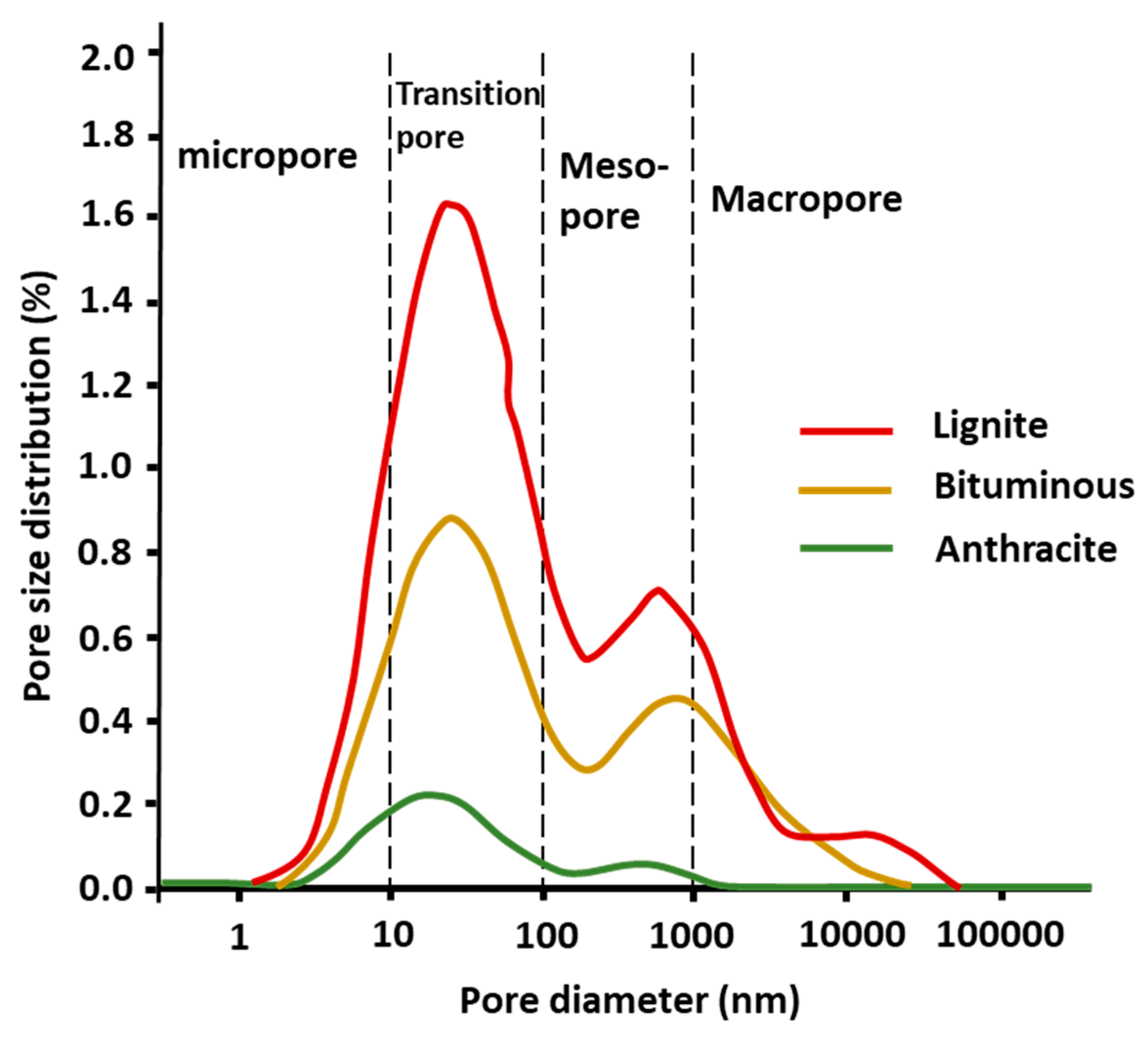
The pore volume in coal is determined by its thermal maturity [71] such that increasing maturity increases the adsorption capacity [2]. Figure 2 presents pore size distribution curves for coals from low rank to high rank as obtained from nuclear magnetic resonance (NMR) analyses [72].
Low-rank coal contains primary epigenetic pores having irregular shapes and poor connectivity. Although the dehydration of lignite to low-rank coal reduces the moisture and oxygen-to-carbon ratio of the material [36], low-rank coal exhibit a high degree of porosity and low pore compressibility [14].
Metamorphism changes pores into circular, oval or slit morphologies [73,74] and medium-rank coal contains pore sizes ranging from macropores to micropores [75]. Medium-rank coal with a high proportion of micropores is the most suitable for industrial methane production [73].
High-rank coals contain primarily micropores with limited pore connectivity as a result the coalification process [49,62]. Coalification also leads to smaller coal pore, larger surface areas, a greater number of micropores and a higher methane content [52,76,77]. Although increases in coal rank are associated with increases in the methane content [78], the pores gradually close and form flattened structure that make gas absorption impossible [35,37,62]. As a result of the small pore surfaces, gas injection into high-rank coal must be performed at high pressures [79].
4. Gas Injection for ECBM Recovery
As noted, CO2, N2 and their mixtures are commonly used for ECBM extraction, and the injection of pure or mixed gas will lead to different adsorption effect, as explained in this section.
4.1. CO2 Injection
CO2 is an acidic gas [80] that is widely for ECBM recovery because it can extract methane with significant efficiency [12]. Coal has a high adsorption affinity for CO2 and so this gas is adsorbed rapidly, whereupon it seeps into micropores [47,64,65,81,82,83,84]. The CO2 molecule also has a small kinetic diameter and so can replace methane originally present in the micropores [12,14,85]. However, the CO2 storage capacity is affected by temperature and pressure, both of which can change the coal structure and permeability [35,43,86,87,88,89,90].
4.2. N2 Injection
N2 is used for ECBM extraction because N2 promotes methane desorption from the coal matrix [12,14,91,92]. N2 reaches equilibrium quickly, leading to a more rapid response [91,93]. N2 adsorption increases with increases in pressure, although, N2 undergoes weak interactions with adsorbents [94,95]. N2 injection also alters the coal pore structure and increases the transition pore volume such that the pore volume, pore size distribution, and connectivity are all increased [96].
4.3. Mixed Gas (CO2-N2) Injection
ECBM recovery experiments using gas mixtures have been carried out, Such mixtures have been found to be applicable to low-permeability coal [13,97] because N2 prevents expansion of the coal matrix and increases the diffusion coefficient to provide faster methane extraction [14]. However, such mixtures are not suitable for carbon sequestration [98].
The desorption of methane is enhanced in the case that the mixed gas has a CO2 concentration of less than 10%. Increasing the proportion of CO2 increases the probability of adsorption while decreasing the desorption of methane [99]. The adsorption selectivity obtainable from a mixed gas injection may be calculated as [99]
where is the adsorption selectivity and, x and y represent the mole fractions of each gas in the adsorbed and bulk phase, respectively. An adsorption selectivity of 1 indicates that N2 is adsorbed more strongly than CO2 while a value greater than 1 indicates the opposite.
5. Gas Adsorption
Temperature and pressure are important factors in ECBM recovery. Higher temperatures lead to reduced gas adsorption capacities, reductions in the residual forces on the coal matrix surface and breaking of the bonds between gas molecules and the coal [92]. In contrast, higher pressures increase the coal adsorption capacity [100]. A higher pressure increases the adsorbate density and provides greater surface coverage and stronger interactions of the adsorbate molecules with the coal [34]. Thus, increasing the temperature is detrimental because this promotes gas desorption rather than adsorption [101]. The present section describes calculations, isotherms and thermodynamic parameters associated with gas adsorption on coal, and discusses modeling used to predict gas adsorption in coal pores.
5.1. Adsorption Calculations
In most cases, coal injection calculations are performed using volumetric and gravimetric methods [102]. However, each method has a different calculation focus and considerations that are affected by the adsorption isotherm. In particular, experimental methods take into account both excess and absolute adsorption with the difference between the two being required to determine the adsorbed phase density [26].
5.1.1. Volumetric Methods
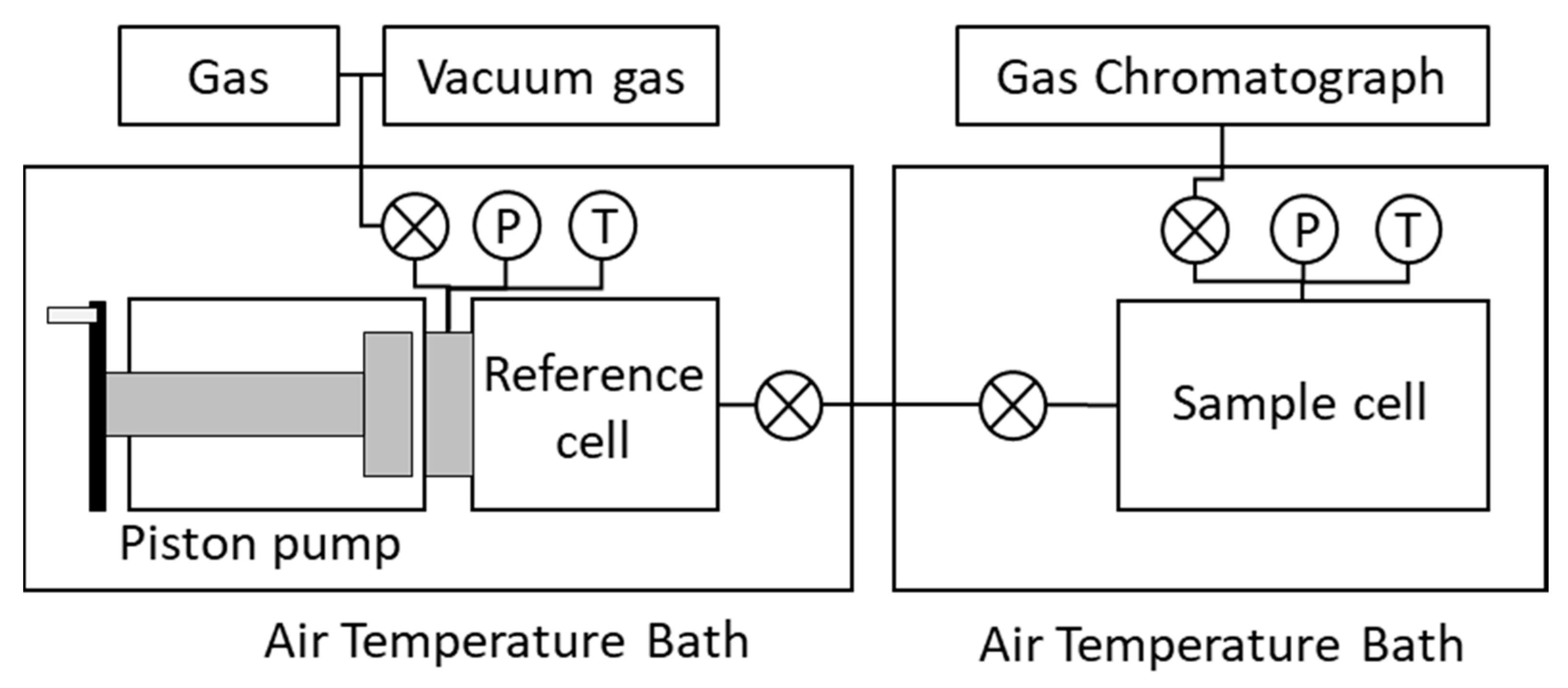
The volumetric/manometric methods are techniques for assessing adsorption based on variations in the pressure of the adsorbate gas in a coal sample [26,55,103,104] (Figure 3). The associated equation is [104]
where is the Gibbs excess adsorption (mmol g−1), P is the pressure (MPa), is the gas volume that is injected(cm3), is the void volume (cm3), R is the ideal gas constant (8.314 J mol−1 K−1), Z is the compressibility factor of the gas, and T is the temperature (). The value of Z is calculated using the equation [92]
where is the acentric factor for the gas, is the reduced pressure (MPa), and is the reduced temperature (). and are, respectively, expressed as [92]
The critical pressure () value for CO2 and N2 are 7.39 MPa and 3.395 MPa, respectively while the critical temperature () values are 304.2 K and 126 K. The acentric factors () for CO2 and N2 are 0.224 and 0.040, respectively.
5.1.2. Gravimetric Methods
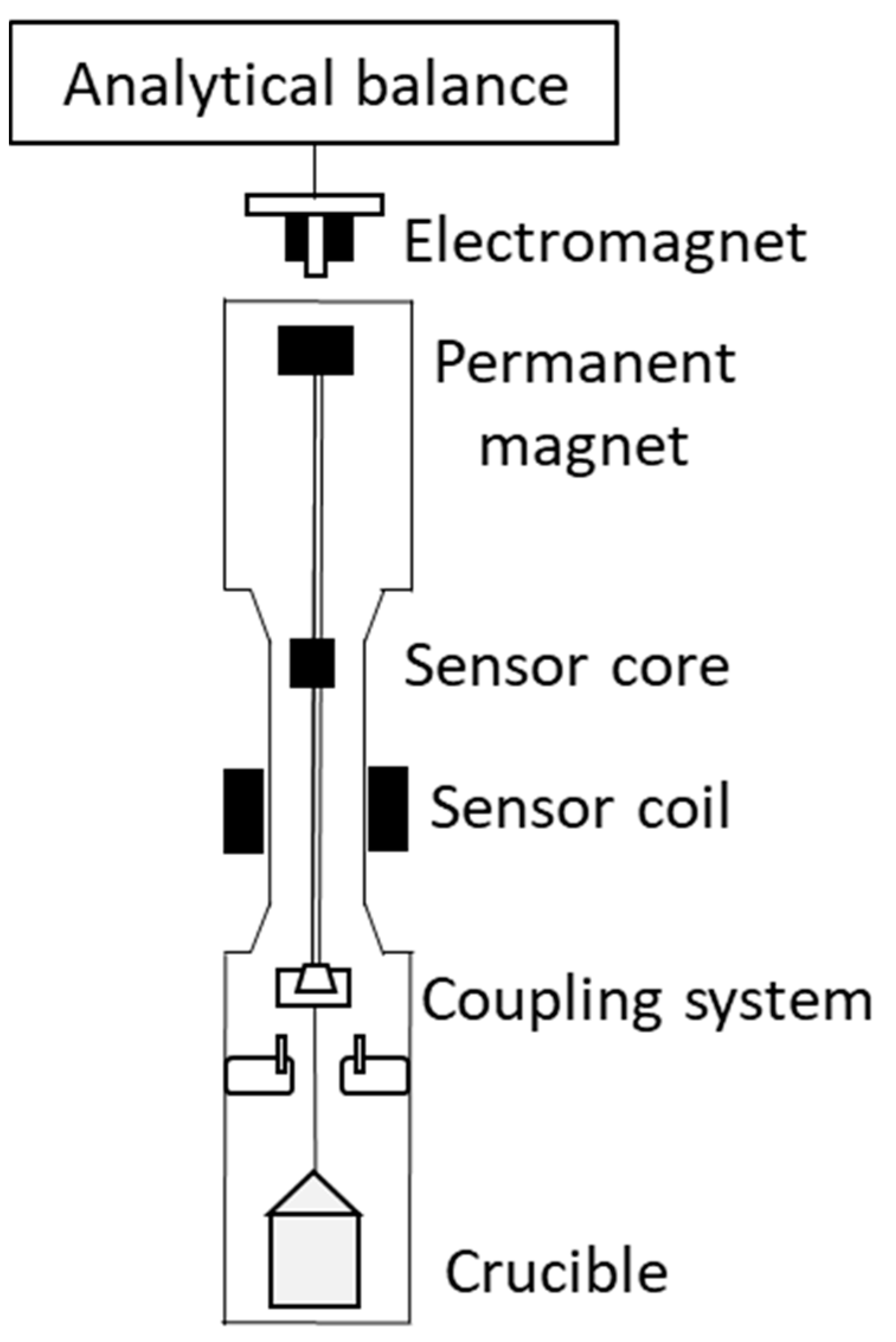
The gravimetric methods are based on the use a microbalance [102] to monitor changes in sample mass during gas adsorption [26,103] (Figure 4). The equation is [26]
where is the Gibbs excess adsorption (mmol/g), is the mass change (g), is the coal sample mass, is the density of the coal sample (g cm−3), and is the density of the gas (g cm−3).
5.2. Modeling for the Prediction of Coal Adsorption
Predictions of coal adsorption have been performed using many mathematical models, with the Ono–Kondo lattice model being commonly used, in addition to numerical simulations. The Ono–Kondo process estimates adsorption on the microscopic scale by considering thermodynamic equilibrium in multilayer adsorption based on the equation [106]
where is the amount of absolute adsorption (mmol g−1), is the bulk density (g cm−3), is the adsorbed phase density at maximum capacity (g cm−3) is the extent of monolayer adsorption (mmol g−1), is Boltzmann’s constant, 1.38 × 10⁻²³ (J mol−1 K−1), and is the interaction energy between the adsorbate molecules and the adsorbent surface (kJ mol−1).
Numerical simulations are used to calculate value within a bidisperse model system using computer codes that describe gas transport during adsorption in coal macropores and micropores. The relevant equations are [83]
where is the adsorbate-wall interaction potential in a micropore (J), is the gas phase density (kmol m−3), is the pore radius (m), D is the gas diffusivity (m2s−1), is the adsorbate concentration (kmol m−3) and the subscripts a and i indicate macropores and micropores, respectively.
5.3. Thermodynamic Parameters
Adsorption on coal surfaces can be understood based on thermodynamic parameters, such as the isosteric heat of adsorption , change in entropy , change in enthalpy , change in Gibbs free energy and surface potential [107]. The isosteric heat parameter can also be used to assess the degree of surface homogeneity [108].
resulting from the interaction between an absorbent and adsorbate, can be calculated as [109]
where R is the ideal gas constant (J mol−1 K−1), T is the temperature (K), P is pressure (MPa) and V is the amount of gas adsorption as determined by the Langmuir method (cm3 g−1).
The energy released from the adsorbate attaching to the adsorbent surface, otherwise known as the surface potential can be determined as [101]
where R is the ideal gas constant (J mol−1 K−1), T is the temperature (K), P is the pressure (MPa) and V is the amount of gas adsorption determined by the Langmuir method (cm3 g−1).
The Gibbs free energy is an indicator of the reaction spontaneity and is calculated as [101]
where is the surface potential and V is the amount of gas adsorption determined by the Langmuir method (cm3 g−1).
The change in entropy is a measure of the variation in order at the gas-solid interface on the coal surface and can be written as [107]
where is the energy change associated with the adsorption process , is the change in Gibbs free energy, and T is the temperature (K).
It is evident that adsorption on the coal surface is affected by temperature, pressure and pore size distribution. Increasing the temperature decreases the isosteric heat of adsorption [101] while increasing the equilibrium pressure reduces the change in entropy and surface potential [101]. A pore system in the coal in which micropores are dominant will be indicated by higher , and values [107].
5.4. Adsorption Isotherms
Adsorption isotherms provide information related to physical adsorption at equilibrium pressure. The most commonly used methods for analyzing adsorption isotherms obtained from coal are the Langmuir, Brunauer–Emmett–Teller (BET), Dubinin–Radushkevich (DR), and Dubinin–Astakhov (DA) techniques. These four methods each assess different types of adsorption and different types of curves. Specifically, the Langmuir D-A and D-R approaches are used with type I isotherms, whereas the BET method is used with type II isotherms [110] (Figure 5). Type I isotherms reflect increased adsorption and pore filling, whereas type II isotherms indicate multilayer physical adsorption [111].
5.4.1. Langmuir Method
The Langmuir method is based on dynamic equilibrium and the result of Langmuir is used conjunction with type I isotherms [110]. This technique produces results similar to experimental data [56] because the Langmuir pressure typically decreases with increases in moisture content [50] and coal rank [53]. The adsorption used in this method calculation is [112]
where P is the equilibrium gas or vapor pressure (MPa), V is the gas adsorption amount (cm3 g−1), VL is the Langmuir monolayer volume constant (cm3 g−1), and PL is the Langmuir pressure at half of VL (MPa). The weakness of the Langmuir model is that it only applies to monolayer adsorption on solid surfaces [113,114].
5.4.2. BET Method
The BET method is used to obtain information regarding multilayers based on as type II isotherms [110]. This technique expands the concept of the Langmuir adsorption isotherm by assuming perfect multilayer adsorption via the formation of monolayers [115]. The BET data are obtained by injecting N2 gas at 77 K into a coal sample and provide information related to the type of pores in which adsorption occurs, the SSA of the material and the total pore volume [37,62,74,96,116,117]. The BET method is also used to calculate the SSA values of mesoporous solids in general [77,118]. The pore types determined from this technique are classified as H1, H2 or H3. The H1 pores promote adsorption whereas the H2 and H3 types are better for desorption and diffusion [74]. The BET equation used to calculate adsorption is [110]
where P is the pressure (MPa), Va is the volume of gas adsorbed (cm3g−1), P/P0 is the relative pressure, Vm is the volume of adsorbate as a monolayer (cm3g−1) and C is a constant related to the net heat of adsorption.
5.4.3. Dubinin Method
The Dubinin method assumes that the adsorbates molecules fill the micropores [110] and the relevant data are obtained by injecting gaseous CO2 at 273 K into a coal sample [119]. This technique uses the D-R equation to analyze micropore capacity and surface area along with the D-A equation compute the pore size distribution [120]. Isotherm equations based on the Dubinin method have been found to reproduce experimental data better than either monolayer or multilayer pore filling models. The relevant equations are [110]
For the D-R method,
For the D-A method
where is the pore volume filled at P/P0 (cm3 g−1), is the total volume of the micropore system (cm3 g−1), β is the sorbate affinity coefficient (mol2 kJ−2), E0 is the characteristic energy (kJ mol−1), R is the ideal gas constant (J mol−1 K−1) and T is the temperature (), and P0/P is the inverse of the relative pressure of the adsorbate.
5.5. Modeling for Predicting Gas Adsorption in Coal Pores
Density functional theory (DFT) is often used to produce models for predicting gas adsorption in coal pores, while the grand canonical Monte Carlo (GCMC) method is employed to simulate adsorption isotherm.
5.5.1. DFT
DFT models can be used to determine the size distributions of micro-, meso-, and macropores, as well as pore structure morphologies [16,121]. DFT is able to calculate a pore size distribution (PSD) based on the use of different adsorbates such as N2 at 77.4 K and CO2 at 273 K with CO2 being more suitable [121]. In the case of narrow micro- and mesopores, DFT methods provide more accurate pore size analysis [122]. This process involves two steps. Initially, a kernel is produced to determine the PSD from test data for use as a reference for subsequent calculation, after which PSD is obtained an integral adsorption equation corresponds to the kernel. This equation is [16,123]
where is the number of moles adsorbed at pressure P, D is the pore size (nm), is the kernel obtained from theoretical isotherms with different pore widths and is the PSD of the heterogeneous solid adsorbent.
Using the DFT method, factors such as the adsorption energy (), formation energy () and cohesive energy () can be calculated as follows [109].
where , , and are the energies of the AB complex (eV) and the A and B isolates, is the energy of the coal sample complex (eV), is the moles of carbon atoms (mol), is the chemical potential of the carbon atoms (eV mol−1), and is the total number of atoms in the coal sample.
5.5.2. GCMC
Using the GCMC method, the chemical potential can be calculated as [124]
where is the chemical potential, is the standard pressure, is the chemical potential, P is the gas reservoir pressure and is the fugacity coefficient.
The first step in calculating gas adsorption using the GCMC approach is modeling the movement of a gas molecule, followed by the generation and then deletion of a gas molecule. The relevant equations are [125]
where is the pressure of movement (MPa), is the pressure of generation (MPa), is the pressure of deletion (MPa), N is the number of gas molecules, is the change in the total potential energy of the system after one of the three steps (J), is the Boltzmann constant (JK−1), is the wavelength (nm), and is the volume (nm3).
These simulation are repeated until equilibrium is achieved after a number of deletion and insertion steps [124]. Based on these GCMC simulations and experimental data, gas adsorption can be calculated using the equation [126]:
where is the excess adsorption amount, is the absolute adsorption amount, is the Avogadro constant, is the pressure (Pa), is the free volume, R is the ideal gas constant (J/mol K) and T is the temperature ().
5.6. Adsorption into the Coal Chemical Structure
Modern techniques, such as Fourier transform infrared (FTIR) Raman, and 13C NMR spectroscopies as well as X-ray diffraction have been applied to the analysis of coal [99]. Low-rank coals have been determined to be primarily composed of oxygen-containing functional groups [49] while medium-rank coals with lower volatile matter content exhibit a high degree of aromatization and lower amount of oxygen-containing functional and aliphatic compounds [127]. High-rank coals contain some oxygen-based functional groups [49].
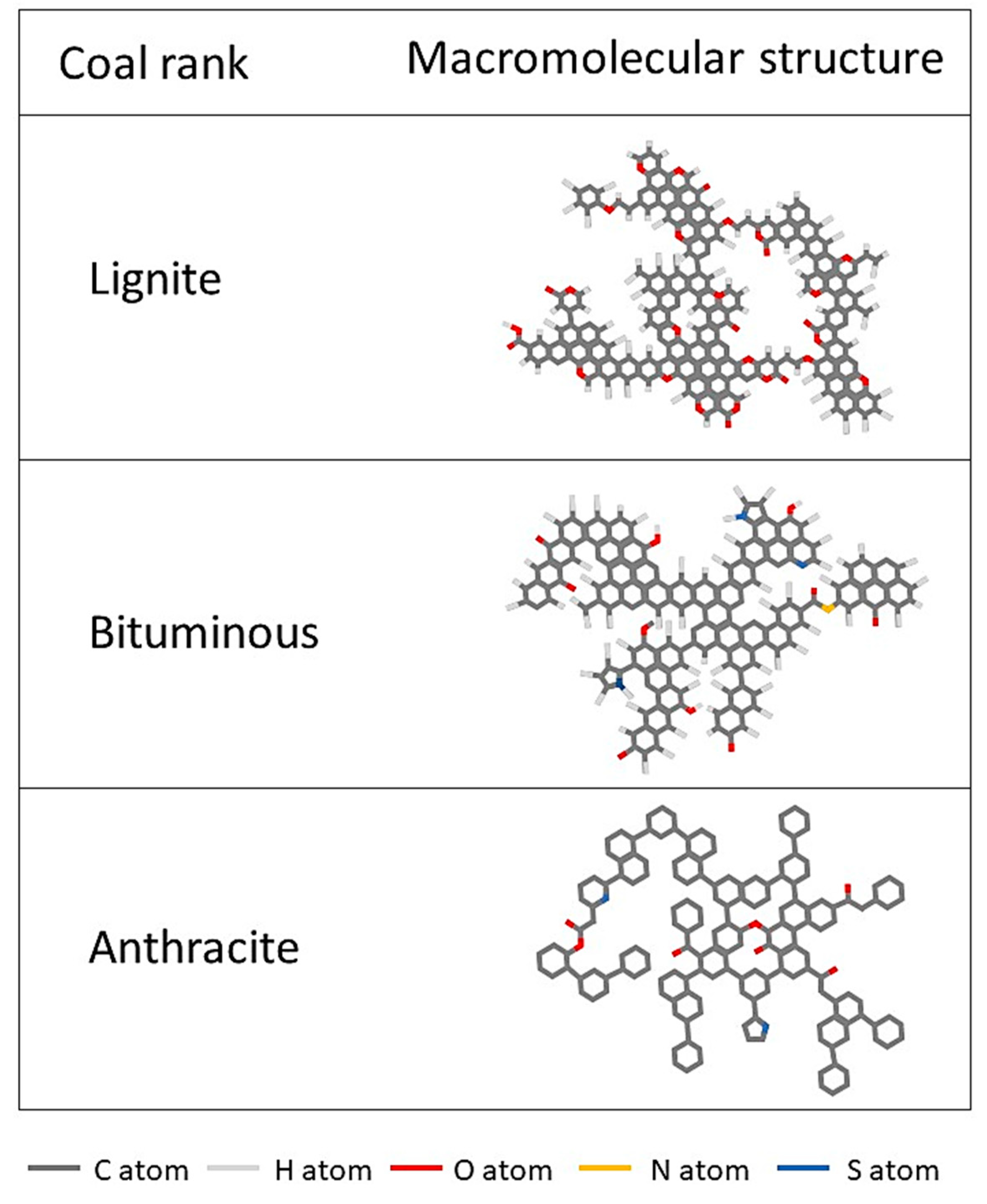
13C NMR can be used to elucidate the macro-molecular structure of coal [99]. Such studies have indicated that lignite exhibits decarboxylation and dehydration, bituminous coals show decarboxylation and hydrogen disproportionation and anthracite contains aromatic rings and shows dehydrogenization (Figure 6). The 13C NMR is data can be processed using the equation [99].
where is the average degree of aromatic ring condensation in the coal structure, is the protonated aromatic carbon, is the oxygen-linked aromaticity carbon, is the side branch aromaticity carbon, and is the bridging aromaticity carbon.
FTIR is used to analyze the functional groups of organic compounds, including aromatic, oxygen-containing, aliphatic, and hydroxyl structures [92,127]. Prior to such analyses, the coal sample should be demineralized [127] and CO2 will generate a peak at 2330 cm−1 [128]. Results from FTIR studies of CO2 adsorption on wet coal indicated a significant decline in CO2 adsorption capacity compared with dry samples, although aliphatic and aromatic functional groups were unaffected [92] (Figure 7).
The Raman method allows the analysis of microcrystalline carbon structure [127] based on signal related to the vibrations of aromatic fused rings [129]. This technique can be used to study gas adsorption coal by evaluating the D peak (1332 to 1366 cm−1) and G peak (1576 to 1608 cm−1) [127].
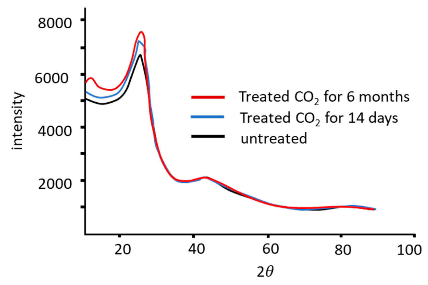
According to [128], coal must be demineralized prior to evaluating gas adsorption using XRD and the difference between treated and untreated coal following gas injection can be clearly seen at the 2 = 23° peak position [128] (Figure 8). The (002) band is the most prominent band in the XRD diffractogram, and change in the position of this peak are related to changes in the aromatic sheet structure (that is, in the interlayer spacing d002) [128,130]. The equations for calculating the interlayer spacing between the aromatic sheets () and the average crystallite stacking height (Lc) are [128]
where is the X-ray wavelength (Å), is the 002 diffraction angle, is the width at half maximum intensity of the pure reflection profile in radians.
6. Adsorption Effects
Previous research has shown that CO2 injection is likely to produce swelling of coal [26,93,131,132], whereas N2 injection is less likely to do so [131,132]. The effect of gas can be assessed using volumetric and gravimetric method and by monitoring tri-axial stress (Table 1). Additional measurement devices, such as strain gauges, strain bridges, linear variable differential transformers (LVDT), and optical analyzers, can be used to assess instantaneous volume changes [102]. Compared with non-pressurized methods, pressure-based techniques can show initial fracturing and tend to indicate higher gas release volumes [133]. Increases in the adsorption pressure promote expansion of the coal matrix that in turn reduces the cleat apertures and closes pre-existing fractures [39,134,135,136,137]. These phenomena decrease the permeability of the coal and inhibit methane production [24,118].
7. Discussion and Prospects for Future Research
Experimental work and simulations methods aimed at understanding gas adsorption during ECBM recovery are being increasingly improved. This review focused on the effects of the chemical structure of coal, taking into account various properties of the coal and the injection gas. Gas adsorption is essentially a solid-liquid system in which adsorption leads to the infusion of a sorbate into a sorbent, which is converted to a rubbery state such that its pores disappear [128]. As a consequence, moisture is an important factor in the adsorption of gas by coal. Experimental data shows that the adsorption by dry coal has higher adsorption capacity than wet coal [49,52,53,54]. Analyze of the chemical structures of coals have established that interactions between hydroxyl and carboxyl functional groups with water molecules are stronger than those with gas molecules [92]. Hence, dry coal will always exhibit higher gas adsorption capacity than wet coal, even though wet coal is the closest to the natural condition of this material.
Demineralized coal is commonly used in coal structural analyses but does not closely match real coal. The various minerals in coal can be dissolved and mobilized during gas adsorption [141] and so a challenge for future research will be to ascertain the effects of mineral content on gas adsorption by coal.
The maceral content of coal and its pore size have a unique correlation. The maceral content is greatly affected by the deposition of coal, whereas pore size is affected by the coalification process. Studies of gas adsorption by coal using FTIR spectroscopy have demonstrated that coal with a higher vitrinite content generates higher adsorption capacity because the small pores of the vitrinite are able to capture gas molecules [142]. Adsorption isotherm analyses using the Langmuir, Dubinin and BET methods will all show differences in the effects of pores in coal. The Langmuir technique assumes monolayer formation, while the BET method postulates the formation of multilayers based on monolayers and the Dubinin calculations are predicated on pore filling. The most significant difference between the Langmuir and BET methods is that the former takes each adsorption site into account but assumes only one molecule at each site, while the BET method calculates the adsorption of several molecules at each site [115]. Adsorption analyses using the BET method indicate minimal variations in the mesopore volume between dry and wet coal [92]. However, the micropore surface area is increased in dry coal and decreased in wet coal [92]. The Dubinin method is better at fitting experimental data than the monolayer or multilayer pore filling models. Differences in pore size and correlations in these differences with coal chemical structures can be examined using XRD by investigating the structural geometry in micropores [128]. Overall, the data show that a higher vitrinite content and more accessible pores promotes gas adsorption and methane desorption from the coal matrix.
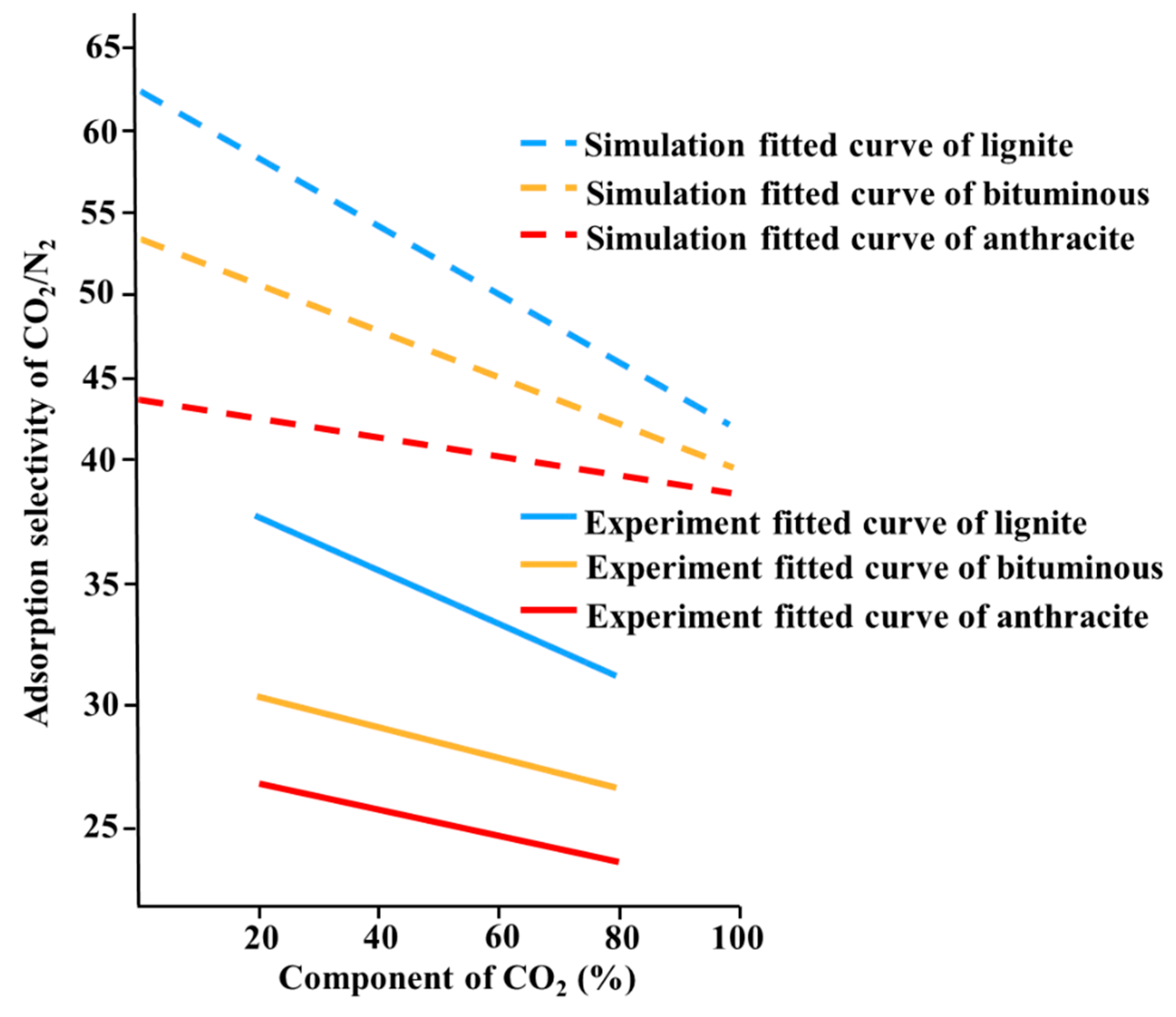
The gas that is injected during ECBM recovery depends on the type of coal being processed. Coal having a higher oxygen content will adsorb CO2 and N2 more strongly because the heat of adsorption of these gases will be higher [99]. Thermodynamic calculations also indicate that CO2 adsorbs to the coal surfaces more readily than N2 and is more stable once adsorbed [101]. The fraction of the coal surface populated by CO2 molecules increases with increases in the heat of CO2 adsorption, indicating higher CO2 adsorption [128]. Both simulations and experimental data regarding adsorption selectivity associated with injecting CO2-N2 mixtures show similar trends in which CO2 is preferentially adsorbed and lower rank coal has higher adsorption selectivity [99] (Figure 9). However, even though CO2 is preferentially adsorbed increasing the percentage of CO2 in the gas mixture makes it more difficult to desorb methane [99]. This phenomenon occurs because CO2 alters the coal pore sizes via internal and external expansion effects [137]. The injection of pure CO2 also results in swelling of the coal such that methane extraction is inhibited. Thus, for the purpose of ECBM recovery, the injection of CO2-N2 mixtures is the best option.
Laboratory experiments using volumetric and gravimetric methods are commonly used to assess gas adsorption by coal. The volumetric methods determine gas adsorption at a variety of pressures but cannot assess variations in volume and density after adsorption [26]. The gravimetric methods are highly accurate but have several weaknesses. Specifically, these techniques require buoyancy correction [102] and make it difficult to control the sample temperature during the experiment [26]. As a consequence of these issues, modeling should be used to improve accuracy.
Modeling-based predictions of gas adsorption have been found to be similar to experimental data, although these models tend to neglect physical adsorption mechanisms. Even though the Ono–Kondo lattice model considers the crystalline coal structure, this technique assumes monolayer adsorption and omits swelling of the coal matrix [106]. Numerical simulations provide better predictions but assume uniform micropores [83]. DFT and GCMC provide improved results. DFT can predict a variety of coal pore sizes while GCMC simulates adsorption based on gas molecule movement, generation, and deletion on coal.
Various methods proposed to understand the adsorption in chemical structures have their respective advantages and disadvantages (Table 2). The 13C NMR detects total aromaticity better than other methods and XRD explains a better aromatic layer than method [143]. The coalification process affects gas adsorption in coal and increasing proportions of aromatic components is related to increasing vitrinite reflectance value [127]. Aliphatic and aromatic in coal are unaffected by water molecules because these groups are hydrophobic [92].
Even though adsorption measurement methods have been improved, there have been few reports related to the use of these techniques to study the injection of mixed gases into coal. This suggests opportunities for future research in this field as a means of examining ECBM by injecting a variety of gases into different coal ranks. An improved understanding of the adsorption processes and more detailed data should allow more accurate simulations of ECBM recovery.
8. Conclusions
This review examined various aspects of gas adsorption by coal during ECBM extraction. The most important factors as affecting this process are follows:
- Moisture
Experimental data show that adsorption is inhibited on wet coal because the adsorption sites are occupied by water molecules. This effect is reinforced by interactions between water molecules and hydroxyl/ carboxyl functional groups in the coal.
- Maceral and pore size
Changes in the coal structural geometry related to the presence of mesopores and micropores as well as chemical structure can affect the extent of gas adsorption in coal pores. The presence of maceral is determined by the type of coal deposit while pore sizes are affected by the coalification process, and these relationships indicate that higher vitrinite proportions and more accessible pores increase the possibility of gas adsorption.
- Gas characteristics
CO2 is adsorbed by coal to a greater extent than N2, although the injection of CO2 alone results in swelling of the coal. The use of CO2-N2 mixture appears to be the best option for ECBM recovery.
- Cutting-edge methods used to understand adsorption
Laboratory experiments using volumetric and gravimetric methods can provide approximate information concerning gas adsorption by coal. However, such experiments also require modeling to ensure accuracy, such as the Ono–Kondo lattice model or numerical simulations. Since such modeling does not take physical mechanisms into account, DFT and GCMC method may also be applied. Analytical techniques including 13C NMR and XRD can also monitor gas adsorption and may provide superior data.
Further research concerning gas adsorption by coal as a means of improving ECBM extraction is required, especially concerning the injection of mixed gases into a variety of coal ranks.
Author Contributions
Conceptualization and methodology, T.N.T., Y.S. and R.N.; writing—original draft and editing, T.N.T.; writing—review Y.S. and R.N. All authors have read and agreed to the published version of the manuscript.
Funding
This research received no external funding.
Institutional Review Board Statement
Not applicable.
Informed Consent Statement
Not applicable.
Data Availability Statement
Not applicable.
Conflicts of Interest
The authors declare no conflict of interest.
References
- Alexis, D.A.; Karpyn, Z.T.; Ertekin, T.; Crandall, D. Fracture permeability and relative permeability of coal and their dependence on stress conditions. J. Unconv. Oil Gas Resour. 2015, 10, 1–10. [Google Scholar] [CrossRef] [Green Version]
- Crosdale, P.J.; Beamish, B.; Valix, M. Coalbed methane sorption related to coal composition. Int. J. Coal Geol. 1998, 35, 147–158. [Google Scholar] [CrossRef]
- Wang, R.; Zhang, N.; Liu, X.; Wu, X.; Chen, J.; Ma, L. Characteristics of Pore Volume Distribution and Methane Adsorption on Shales. Adsorpt. Sci. Technol. 2015, 33, 915–938. [Google Scholar] [CrossRef]
- Bae, J.-S.; Bhatia, S.K.; Rudolph, V.; Massarotto, P. Pore Accessibility of Methane and Carbon Dioxide in Coals. Energy Fuels 2009, 23, 3319–3327. [Google Scholar] [CrossRef]
- Lu, T.; Yu, H.; Zhou, T.; Mao, J.; Guo, B. Improvement of methane drainage in high gassy coal seam using waterjet technique. Int. J. Coal Geol. 2009, 79, 40–48. [Google Scholar] [CrossRef]
- Keshavarz, A.; Badalyan, A.; Carageorgos, T.; Bedrikovetsky, P.; Johnson, R. Stimulation of coal seam permeability by micro-sized graded proppant placement using selective fluid properties. Fuel 2015, 144, 228–236. [Google Scholar] [CrossRef]
- Umezaki, T.; Kawamura, T.; Okamoto, K.; Hattori, A.; Kobayashi, Y. Swelling properties and coefficient of permeability of friction-reducing polymer for pull-out of temporary sheet piles. Soils Found. 2018, 58, 797–807. [Google Scholar] [CrossRef]
- Ahamed, M.; Perera, M.; Dong-Yin, L.; Ranjith, P.; Matthai, S. Proppant damage mechanisms in coal seam reservoirs during the hydraulic fracturing process: A review. Fuel 2019, 253, 615–629. [Google Scholar] [CrossRef]
- Lyu, S.; Wang, S.; Chen, X.; Shah, S.; Li, R.; Xiao, Y.; Dong, Q.; Gu, Y. Experimental study of a degradable polymer drilling fluid system for coalbed methane well. J. Pet. Sci. Eng. 2019, 178, 678–690. [Google Scholar] [CrossRef]
- Li, Z.; Wei, G.; Liang, R.; Shi, P.; Wen, H.; Zhou, W. LCO2-ECBM technology for preventing coal and gas outburst: Integrated effect of permeability improvement and gas displacement. Fuel 2021, 285, 119219. [Google Scholar] [CrossRef]
- Zarrouk, S.J.; Moore, T. Preliminary reservoir model of enhanced coalbed methane (ECBM) in a subbituminous coal seam, Huntly Coalfield, New Zealand. Int. J. Coal Geol. 2009, 77, 153–161. [Google Scholar] [CrossRef]
- Shimada, S.; Li, H.; Oshima, Y.; Adachi, K. Displacement behavior of CH4 adsorbed on coals by injecting pure CO2, N2, and CO2–N2 mixture. Environ. Earth Sci. 2005, 49, 44–52. [Google Scholar] [CrossRef]
- Seomoon, H.; Lee, M.; Sung, W. Analysis of methane recovery through CO 2 –N 2 mixed gas injection considering gas diffusion phenomenon in coal seam. Energy Explor. Exploit. 2016, 34, 661–675. [Google Scholar] [CrossRef] [Green Version]
- Oudinot, A.Y.; Riestenberg, D.E.; Koperna, G.J. Enhanced Gas Recovery and CO2 Storage in Coal Bed Methane Reservoirs with N2 Co-Injection. Energy Procedia 2017, 114, 5356–5376. [Google Scholar] [CrossRef]
- Cho, S.; Kim, S.; Kim, J. Life-cycle energy, cost, and CO2 emission of CO2-enhanced coalbed methane (ECBM) recovery framework. J. Nat. Gas Sci. Eng. 2019, 70, 102953. [Google Scholar] [CrossRef]
- Qi, L.; Tang, X.; Wang, Z.; Peng, X. Pore characterization of different types of coal from coal and gas outburst disaster sites using low temperature nitrogen adsorption approach. Int. J. Min. Sci. Technol. 2017, 27, 371–377. [Google Scholar] [CrossRef]
- Godec, M.; Koperna, G.; Gale, J. CO2-ECBM: A Review of its Status and Global Potential. Energy Procedia 2014, 63, 5858–5869. [Google Scholar] [CrossRef] [Green Version]
- Mukherjee, M.; Misra, S. A review of experimental research on Enhanced Coal Bed Methane (ECBM) recovery via CO2 sequestration. Earth-Sci. Rev. 2018, 179, 392–410. [Google Scholar] [CrossRef]
- Harpalani, S.; Ouyang, S. A New Laboratory Technique to Estimate Gas Diffusion Characteristics of Coals. In Proceedings of the International Coalbed Methane Symposium, Tuscaloosa, AL, USA, 11–17 June 1999; pp. 141–149. [Google Scholar]
- Vishal, V.; Mahanta, B.; Pradhan, S.; Singh, T.; Ranjith, P. Simulation of CO2 enhanced coalbed methane recovery in Jharia coalfields, India. Energy 2018, 159, 1185–1194. [Google Scholar] [CrossRef]
- Pan, Z.; Connell, L.D. A theoretical model for gas adsorption-induced coal swelling. Int. J. Coal Geol. 2007, 69, 243–252. [Google Scholar] [CrossRef]
- Kim, H.J.; Shi, Y.; He, J.; Lee, H.-H.; Lee, C.-H. Adsorption characteristics of CO2 and CH4 on dry and wet coal from subcritical to supercritical conditions. Chem. Eng. J. 2011, 171, 45–53. [Google Scholar] [CrossRef]
- Hol, S.; Peach, C.J.; Spiers, C.J. Applied stress reduces the CO2 sorption capacity of coal. Int. J. Coal Geol. 2011, 85, 128–142. [Google Scholar] [CrossRef]
- Pan, Z.; Connell, L.D. Modelling permeability for coal reservoirs: A review of analytical models and testing data. Int. J. Coal Geol. 2012, 92, 1–44. [Google Scholar] [CrossRef]
- White, C.M.; Smith, D.H.; Jones, K.L.; Goodman, A.L.; Jikich, S.A.; LaCount, R.B.; DuBose, S.B.; Ozdemir, E.; Morsi, A.B.I.; Schroeder, K.T. Sequestration of Carbon Dioxide in Coal with Enhanced Coalbed Methane Recovery—A Review. Energy Fuels 2005, 19, 659–724. [Google Scholar] [CrossRef]
- Busch, A.; Gensterblum, Y. CBM and CO2-ECBM related sorption processes in coal: A review. Int. J. Coal Geol. 2011, 87, 49–71. [Google Scholar] [CrossRef]
- Susilawati, R.; Esterle, J.S.; Golding, S.D.; Mares, T.E. Microbial Methane Potential for the South Sumatra Basin Coal: Formation Water Screening and Coal Substrate Bioavailability. Energy Procedia 2015, 65, 282–291. [Google Scholar] [CrossRef] [Green Version]
- Saghafi, A. Potential for ECBM and CO2 storage in mixed gas Australian coals. Int. J. Coal Geol. 2010, 82, 240–251. [Google Scholar] [CrossRef]
- Ahmed, M.; Smith, J. Biogenic methane generation in the degradation of eastern Australian Permian coals. Org. Geochem. 2001, 32, 809–816. [Google Scholar] [CrossRef]
- Moore, T.A. Coalbed methane: A review. Int. J. Coal Geol. 2012, 101, 36–81. [Google Scholar] [CrossRef]
- Scott, A.R.; Kaiser, W.R.; Ayers, W.B. Thermogenic and secondary biogenic gases, San Juan Basin, Colorado and New Mexico—Implications for coalbed gas producibility. Am. Assoc. Pet. Geol. Bull. 1994, 78, 1186–1209. [Google Scholar] [CrossRef]
- Rice, D.D. Composition and Origins of Coalbed Gas. AAPG Bull. 1993, 77. [Google Scholar] [CrossRef]
- Al-Mahmoud, M.J.; Inan, S.; Al-Duaiji, A.A. Coal occurrence in the Jurassic Dhruma Formation in Saudi Arabia: Inferences on its gas and surface mining potential. Int. J. Coal Geol. 2014, 124, 5–10. [Google Scholar] [CrossRef]
- Zheng, Y.; Li, Q.; Yuan, C.; Tao, Q.; Zhao, Y.; Zhang, G.; Liu, J. Influence of temperature on adsorption selectivity: Coal-based activated carbon for CH4 enrichment from coal mine methane. Powder Technol. 2019, 347, 42–49. [Google Scholar] [CrossRef]
- Merkel, A.; Gensterblum, Y.; Krooss, B.; Amann-Hildenbrand, A. Competitive sorption of CH4, CO2 and H2O on natural coals of different rank. Int. J. Coal Geol. 2015, 150–151, 181–192. [Google Scholar] [CrossRef]
- Levine, J.R. Coalification: The Evolution of Coal as a Source Rock and Reservoir Rock for Oil and Gas. In Hydrocarbon in Coal; Law, B.E., Rice, D.D., Eds.; American Association of Petroleum Geologists Studies in Geology: Tuscaloosa, AL, USA, 1993; Volume 38, pp. 39–77. [Google Scholar]
- Li, Y.; Zhang, C.; Tang, D.; Gan, Q.; Niu, X.; Wang, K.; Shen, R. Coal pore size distributions controlled by the coalification process: An experimental study of coals from the Junggar, Ordos and Qinshui basins in China. Fuel 2017, 206, 352–363. [Google Scholar] [CrossRef]
- Olajossy, A. Some parameters of coal methane system that cause very slow release of methane from virgin coal beds (CBM). Int. J. Min. Sci. Technol. 2017, 27, 321–326. [Google Scholar] [CrossRef]
- Pone, J.D.N.; Halleck, P.M.; Mathews, J.P. Sorption Capacity and Sorption Kinetic Measurements of CO2 and CH4 in Confined and Unconfined Bituminous Coal. Energy Fuels 2009, 23, 4688–4695. [Google Scholar] [CrossRef]
- Kim, D.; Seo, Y.; Kim, J.; Han, J.; Lee, Y. Experimental and Simulation Studies on Adsorption and Diffusion Characteristics of Coalbed Methane. Energies 2019, 12, 3445. [Google Scholar] [CrossRef] [Green Version]
- Busch, A.; Krooss, B.; Gensterblum, Y.; van Bergen, F.; Pagnier, H. High-pressure adsorption of methane, carbon dioxideand their mixtures on coals with a special focus on the preferential sorption behaviour. J. Geochem. Explor. 2003, 78–79, 671–674. [Google Scholar] [CrossRef]
- Mastalerz, M.; Gluskoter, H.; Rupp, J. Carbon dioxide and methane sorption in high volatile bituminous coals from Indiana, USA. Int. J. Coal Geol. 2004, 60, 43–55. [Google Scholar] [CrossRef]
- Battistutta, E.; van Hemert, P.; Lutynski, M.; Bruining, H.; Wolf, K.-H. Swelling and sorption experiments on methane, nitrogen and carbon dioxide on dry Selar Cornish coal. Int. J. Coal Geol. 2010, 84, 39–48. [Google Scholar] [CrossRef]
- Ozdemir, E.; I Morsi, B.; Schroeder, K. CO2 adsorption capacity of argonne premium coals. Fuel 2004, 83, 1085–1094. [Google Scholar] [CrossRef]
- Skoczylas, N.; Pajdak, A.; Młynarczuk, M. CO2 Adsorption–Desorption Kinetics from the Plane Sheet of Hard Coal and Associated Shrinkage of the Material. Energies 2019, 12, 4013. [Google Scholar] [CrossRef] [Green Version]
- Švábová, M.; Weishauptová, Z.; Přibyl, O. The effect of moisture on the sorption process of CO2 on coal. Fuel 2012, 92, 187–196. [Google Scholar] [CrossRef]
- Busch, A.; Gensterblum, Y.; Krooss, B.; Littke, R. Methane and carbon dioxide adsorption–diffusion experiments on coal: Upscaling and modeling. Int. J. Coal Geol. 2004, 60, 151–168. [Google Scholar] [CrossRef]
- Crosdale, P.J.; Moore, T.; Mares, T. Influence of moisture content and temperature on methane adsorption isotherm analysis for coals from a low-rank, biogenically-sourced gas reservoir. Int. J. Coal Geol. 2008, 76, 166–174. [Google Scholar] [CrossRef]
- Chen, M.-Y.; Cheng, Y.-P.; Li, H.-R.; Wang, L.; Jin, K.; Dong, J. Impact of inherent moisture on the methane adsorption characteristics of coals with various degrees of metamorphism. J. Nat. Gas Sci. Eng. 2018, 55, 312–320. [Google Scholar] [CrossRef]
- Guo, H.; Cheng, Y.; Wang, L.; Lu, S.; Jin, K. Experimental study on the effect of moisture on low-rank coal adsorption characteristics. J. Nat. Gas Sci. Eng. 2015, 24, 245–251. [Google Scholar] [CrossRef]
- Hao, D.; Zhang, L.; Li, M.; Tu, S.; Zhang, C.; Bai, Q.; Wang, C. Experimental study of the moisture content influence on CH4 adsorption and deformation characteristics of cylindrical bituminous coal core. Adsorpt. Sci. Technol. 2018, 36, 1512–1537. [Google Scholar] [CrossRef] [Green Version]
- Cai, Y.; Liu, D.; Pan, Z.; Yao, Y.; Li, J.; Qiu, Y. Pore structure and its impact on CH4 adsorption capacity and flow capability of bituminous and subbituminous coals from Northeast China. Fuel 2013, 103, 258–268. [Google Scholar] [CrossRef]
- Laxminarayana, C.; Crosdale, P.J. Role of coal type and rank on methane sorption characteristics of Bowen Basin, Australia coals. Int. J. Coal Geol. 1999, 40, 309–325. [Google Scholar] [CrossRef]
- Li, J.; Li, B. Evolution features of coal matrix porosity with the variation in temperature and stress. IOP Conf. Ser. Mater. Sci. Eng. 2017, 191, 12050. [Google Scholar] [CrossRef] [Green Version]
- Siemons, N.; Busch, A. Measurement and interpretation of supercritical CO2 sorption on various coals. Int. J. Coal Geol. 2007, 69, 229–242. [Google Scholar] [CrossRef]
- Kumar, H.; Mishra, M.K.; Mishra, S. Sorption capacity of Indian coal and its variation with rank parameters. J. Pet. Explor. Prod. Technol. 2019, 9, 2175–2184. [Google Scholar] [CrossRef] [Green Version]
- Yalçin, E.; Durucan, Ş. Methane capacities of Zonguldak coals and the factors affecting methane adsorption. Min. Sci. Technol. 1991, 13, 215–222. [Google Scholar] [CrossRef]
- Faiz, M.M.; Aziz, N.I.; Hutton, A.C.; Jones, B.G. Porosity and gas sorption capacity of some eastern Australian coals in relation to coal rank and composition. Coalbed Methane Symp. 1992, 19, 9–13. [Google Scholar]
- Karayiğit, A.I.; Mastalerz, M.; Oskay, R.G.; Buzkan, I. Bituminous coal seams from underground mines in the Zonguldak Basin (NW Turkey): Insights from mineralogy, coal petrography, Rock-Eval pyrolysis, and meso-and microporosity. Int. J. Coal Geol. 2018, 199, 91–112. [Google Scholar] [CrossRef]
- Fitzgerald, J.; Pan, Z.; Sudibandriyo, M.; Robinson, J.R.; Gasem, K.; Reeves, S. Adsorption of methane, nitrogen, carbon dioxide and their mixtures on wet Tiffany coal. Fuel 2005, 84, 2351–2363. [Google Scholar] [CrossRef]
- Bustin, R.; Clarkson, C. Geological controls on coalbed methane reservoir capacity and gas content. Int. J. Coal Geol. 1998, 38, 3–26. [Google Scholar] [CrossRef]
- Shen, J.; Qin, Y.; Zhao, J. Maceral Contribution to Pore Size Distribution in Anthracite in the South Qinshui Basin. Energy Fuels 2019, 33, 7234–7243. [Google Scholar] [CrossRef]
- Rodrigues, C.F.A.; de Sousa, M.J.L. The measurement of coal porosity with different gases. Int. J. Coal Geol. 2002, 48, 245–251. [Google Scholar] [CrossRef] [Green Version]
- Beamish, B.; Crosdale, P.J. Instantaneous outbursts in underground coal mines: An overview and association with coal type. Int. J. Coal Geol. 1998, 35, 27–55. [Google Scholar] [CrossRef]
- Karacan, C.; Mitchell, G.D. Behavior and effect of different coal microlithotypes during gas transport for carbon dioxide sequestration into coal seams. Int. J. Coal Geol. 2003, 53, 201–217. [Google Scholar] [CrossRef]
- Larsen, J.W. The effects of dissolved CO2 on coal structure and properties. Int. J. Coal Geol. 2004, 57, 63–70. [Google Scholar] [CrossRef]
- Unsworth, J.F.; Fowler, C.S.; Jones, L.F. Moisture in coal: 2. Maceral effects on pore structure. Fuel 1989, 68, 18–26. [Google Scholar] [CrossRef]
- Keshavarz, A.; Sakurovs, R.; Grigore, M.; Sayyafzadeh, M. Effect of maceral composition and coal rank on gas diffusion in Australian coals. Int. J. Coal Geol. 2017, 173, 65–75. [Google Scholar] [CrossRef]
- Brandani, S.; Mangano, E.; Sarkisov, L. Net, excess and absolute adsorption and adsorption of helium. Adsorption 2016, 22, 261–276. [Google Scholar] [CrossRef] [Green Version]
- Zhou, Y.; Zhang, R.; Huang, J.; Li, Z.; Zhao, Z.; Zeng, Z. Effects of pore structure and methane adsorption in coal with alkaline treatment. Fuel 2019, 254, 115600. [Google Scholar] [CrossRef]
- Bakshi, T.; Prusty, B.; Pathak, K.; Nayak, B.; Mani, D.; Pal, S. Source rock characteristics and pore characterization of Indian shale. J. Nat. Gas Sci. Eng. 2017, 45, 761–770. [Google Scholar] [CrossRef]
- Qin, L.; Li, S.; Zhai, C.; Lin, H.; Zhao, P.; Yan, M.; Ding, Y.; Shi, Y. Joint analysis of pores in low, intermediate, and high rank coals using mercury intrusion, nitrogen adsorption, and nuclear magnetic resonance. Powder Technol. 2020, 362, 615–627. [Google Scholar] [CrossRef]
- Li, S.; Tang, D.; Xu, H.; Yang, Z. The pore-fracture system properties of coalbed methane reservoirs in the Panguan Syncline, Guizhou, China. Geosci. Front. 2012, 3, 853–862. [Google Scholar] [CrossRef] [Green Version]
- Li, Z.; Liu, D.; Cai, Y.; Wang, Y.; Teng, J. Adsorption pore structure and its fractal characteristics of coals by N2 adsorption/desorption and FESEM image analyses. Fuel 2019, 257, 116031. [Google Scholar] [CrossRef]
- Clarkson, C.; Bustin, R. The effect of pore structure and gas pressure upon the transport properties of coal: A laboratory and modeling study. 1. Isotherms and pore volume distributions. Fuel 1999, 78, 1333–1344. [Google Scholar] [CrossRef]
- Parkash, S.; Chakrabartty, S. Microporosity in Alberta Plains coals. Int. J. Coal Geol. 1986, 6, 55–70. [Google Scholar] [CrossRef]
- Sun, W.; Feng, Y.; Jiang, C.; Chu, W. Fractal characterization and methane adsorption features of coal particles taken from shallow and deep coalmine layers. Fuel 2015, 155, 7–13. [Google Scholar] [CrossRef]
- Yao, Y.; Liu, D. Effects of igneous intrusions on coal petrology, pore-fracture and coalbed methane characteristics in Hongyang, Handan and Huaibei coalfields, North China. Int. J. Coal Geol. 2012, 96–97, 72–81. [Google Scholar] [CrossRef]
- Staib, G.; Sakurovs, R.; Gray, E.M.A. A pressure and concentration dependence of CO2 diffusion in two Australian bituminous coals. Int. J. Coal Geol. 2013, 116–117, 106–116. [Google Scholar] [CrossRef]
- Zhou, Y.; Li, Z.; Zhang, R.; Wang, G.; Yu, H.; Sun, G.; Chen, L. CO2 injection in coal: Advantages and influences of temperature and pressure. Fuel 2018, 236, 493–500. [Google Scholar] [CrossRef]
- Yamazaki, T.; Aso, K.; Chinju, J. Japanese potential of CO2 sequestration in coal seams. Appl. Energy 2006, 83, 911–920. [Google Scholar] [CrossRef]
- Busch, A.; Gensterblum, Y.; Krooss, B.M. High-Pressure Sorption of Nitrogen, Carbon Dioxide, and their Mixtures on Argonne Premium Coals. Energy Fuels 2007, 21, 1640–1645. [Google Scholar] [CrossRef]
- Cui, X.; Bustin, R.; Dipple, G. Selective transport of CO2, CH4, and N2 in coals: Insights from modeling of experimental gas adsorption data. Fuel 2004, 83, 293–303. [Google Scholar] [CrossRef]
- Zheng, G.; Pan, Z.; Tang, S.; Ling, B.; Lv, D.; Connell, L.D. Laboratory and Modeling Study on Gas Diffusion with Pore Structures in Different-Rank Chinese Coals. Energy Explor. Exploit. 2013, 31, 859–877. [Google Scholar] [CrossRef] [Green Version]
- Bhowmik, S.; Dutta, P. Adsorption rate characteristics of methane and CO2 in coal samples from Raniganj and Jharia coalfields of India. Int. J. Coal Geol. 2013, 113, 50–59. [Google Scholar] [CrossRef]
- Charrière, D.; Pokryszka, Z.; Behra, P. Effect of pressure and temperature on diffusion of CO2 and CH4 into coal from the Lorraine basin (France). Int. J. Coal Geol. 2010, 81, 373–380. [Google Scholar] [CrossRef]
- Zhao, J.; Tang, D.; Qin, Y.; Xu, H.; Liu, Y.; Wu, H. Characteristics of Methane (CH4) Diffusion in Coal and Its Influencing Factors in the Qinshui and Ordos Basins. Energy Fuels 2018, 32, 1196–1205. [Google Scholar] [CrossRef]
- Li, X.; Yan, X.; Kang, Y. Effect of temperature on the permeability of gas adsorbed coal under triaxial stress conditions. J. Geophys. Eng. 2017, 15, 386–396. [Google Scholar] [CrossRef] [Green Version]
- Fang, H.; Sang, S.; Liu, S. The coupling mechanism of the thermal-hydraulic-mechanical fields in CH4-bearing coal and its application in the CO2-enhanced coalbed methane recovery. J. Pet. Sci. Eng. 2019, 181, 106177. [Google Scholar] [CrossRef]
- Wang, X.; Zhang, D.; Su, E.; Jiang, Z.; Wang, C.; Chu, Y.; Ye, C. Pore structure and diffusion characteristics of intact and tectonic coals: Implications for selection of CO2 geological sequestration site. J. Nat. Gas Sci. Eng. 2020, 81, 103388. [Google Scholar] [CrossRef]
- Dutta, A. Multicomponent Gas Diffusion and Adsorption in Coals for Enhanced Methane Recovery. Master’s Thesis, Stanford University, Stanford, USA, June 2009. [Google Scholar]
- Abunowara, M.; Sufian, S.; Bustam, M.A.; Eldemerdash, U.; Suleman, H.; Bencini, R.; Assiri, M.A.; Ullah, S.; Al-Sehemi, A.G. Experimental measurements of carbon dioxide, methane and nitrogen high-pressure adsorption properties onto Malaysian coals under various conditions. Energy 2020, 210, 118575. [Google Scholar] [CrossRef]
- George, J.S.; Barakat, M. The change in effective stress associated with shrinkage from gas desorption in coal. Int. J. Coal Geol. 2001, 45, 105–113. [Google Scholar] [CrossRef]
- Joewondo, N. Pore Sturucture of Micro and Mesoporous Mudrocks Based on Nitrogen and Carbon Sorption. Master’s Thesis, Colorado School of Mines, Golden, Colorado, 2018. [Google Scholar]
- Aleghafouri, A.; Mohsen-Nia, M.; Mohajeri, A.; Mahdyarfar, M.; Asghari, M. Micropore Size Analysis of Activated Carbons Using Nitrogen, Carbon Dioxide and Methane Adsorption Isotherms: Experimental and Theoretical Studies. Adsorpt. Sci. Technol. 2012, 30, 307–316. [Google Scholar] [CrossRef] [Green Version]
- Wang, H.; Fu, X.; Jian, K.; Li, T.; Luo, P. Changes in coal pore structure and permeability during N 2 injection. J. Nat. Gas Sci. Eng. 2015, 27, 1234–1241. [Google Scholar] [CrossRef]
- Fang, Z.; Li, X.; Hu, H. Gas mixture enhance coalbed methane recovery technology: Pilot tests. Energy Procedia 2011, 4, 2144–2149. [Google Scholar] [CrossRef] [Green Version]
- Reeves, S. The Coal-Seq Project: Key Results from Field, Laboratory, and Modeling Studies. Greenh. Gas Control Technol. 2005, II, 1399–1403. [Google Scholar]
- Zhu, H.; He, X.; Xie, Y.; Guo, S.; Huo, Y.; Wang, W. A Study on the Effect of Coal Metamorphism on the Adsorption Characteristics of a Binary Component System: CO2 and N2. ACS Omega 2020, 6, 523–532. [Google Scholar] [CrossRef]
- Zhang, L.; Aziz, N.; Ren, T.X.; Wang, Z. Influence of Temperature on Coal Sorption Characteristics and the Theory of Coal Surface Free Energy. Procedia Eng. 2011, 26, 1430–1439. [Google Scholar] [CrossRef] [Green Version]
- Hao, M.; Qiao, Z.; Zhang, H.; Wang, Y.; Li, Y. Thermodynamic Analysis of CH4/CO2/N2 Adsorption on Anthracite Coal: Investigated by Molecular Simulation. Energy Fuels 2021, 35, 4246–4257. [Google Scholar] [CrossRef]
- Romanov, V.; Soong, Y.; Schroeder, K. Volumetric Effects in Coal Sorption Capacity Measurements. Chem. Eng. Technol. 2006, 29, 368–374. [Google Scholar] [CrossRef]
- Day, S.; Duffy, G.; Saghafi, A.; Sakurovs, R. Factors controlling CO2 absorption in Australian coals. Greenh. Gas Control. Technol. 2005, 2, 2519–2523. [Google Scholar] [CrossRef]
- Sudibandriyo, M.; Pan, Z.; Fitzgerald, J.E.; Robinson, R.L.; Gasem, K.A.M. Adsorption of Methane, Nitrogen, Carbon Dioxide, and Their Binary Mixtures on Dry Activated Carbon at 318.2 K and Pressures up to 13.6 MPa. Langmuir 2003, 19, 5323–5331. [Google Scholar] [CrossRef]
- De Weireld, G.; Frere, M.; Jadot, R. Automated determination of high-temperature and high-pressure gas adsorption isotherms using a magnetic suspension balance. Meas. Sci. Technol. 1999, 10, 117–126. [Google Scholar] [CrossRef]
- Zhang, Y.; Xing, W.; Liu, S.; Liu, Y.; Yang, M.; Zhao, J.; Song, Y. Pure methane, carbon dioxide, and nitrogen adsorption on anthracite from China over a wide range of pressures and temperatures: Experiments and modeling. RSC Adv. 2015, 5, 52612–52623. [Google Scholar] [CrossRef]
- Du, X.; Cheng, Y.; Liu, Z.; Yin, H.; Wu, T.; Huo, L.; Shu, C. CO2 and CH4 adsorption on different rank coals: A thermodynamics study of surface potential, Gibbs free energy change and entropy loss. Fuel 2021, 283, 118886. [Google Scholar] [CrossRef]
- Deng, J.; Kang, J.; Zhou, F.; Li, H.; Zhang, D.; Li, G. The adsorption heat of methane on coal: Comparison of theoretical and calorimetric heat and model of heat flow by microcalorimeter. Fuel 2019, 237, 81–90. [Google Scholar] [CrossRef]
- Liu, X.-Q.; He, X.; Qiu, N.-X.; Yang, X.; Tian, Z.-Y.; Li, M.-J.; Xue, Y. Molecular simulation of CH4, CO2, H2O and N2 molecules adsorption on heterogeneous surface models of coal. Appl. Surf. Sci. 2016, 389, 894–905. [Google Scholar] [CrossRef]
- Clarkson, C.; Bustin, R.; Levy, J. Application of the mono/multilayer and adsorption potential theories to coal methane adsorption isotherms at elevated temperature and pressure. Carbon 1997, 35, 1689–1705. [Google Scholar] [CrossRef]
- Kumar, A. Adsorption of Methane on Activated Carbon by Volumetric Method. Chem. Eng. 2011. [Google Scholar] [CrossRef]
- Langmuir, I. The adsorption of gases on plane surfaces of glass, mica and platinum. J. Am. Chem. Soc. 1918, 40, 1361–1403. [Google Scholar] [CrossRef] [Green Version]
- Adams, J.J. Asphaltene Adsorption, a Literature Review. Energy Fuels 2014, 28, 2831–2856. [Google Scholar] [CrossRef]
- Montoya, T.; Coral, D.; Franco, C.A.; Nassar, N.N.; Cortés, F.B. A Novel Solid–Liquid Equilibrium Model for Describing the Adsorption of Associating Asphaltene Molecules onto Solid Surfaces Based on the “Chemical Theory”. Energy Fuels 2014, 28, 4963–4975. [Google Scholar] [CrossRef]
- Keller, J.U.; Staudt, R. Gas Adsorption Equilibria: Experimental Methods and Adsorptive Isotherms; Springer: Berlin/Heidelberg, Germany, 2005; ISBN 0387235981. [Google Scholar]
- Zhao, J.; Xu, H.; Tang, D.; Mathews, J.P.; Li, S.; Tao, S. A comparative evaluation of coal specific surface area by CO2 and N2 adsorption and its influence on CH4 adsorption capacity at different pore sizes. Fuel 2016, 183, 420–431. [Google Scholar] [CrossRef]
- Zhu, Q.; Yang, Y.; Lu, X.; Liu, D.; Li, X.; Zhang, Q.; Cai, Y. Pore Structure of Coals by Mercury Intrusion, N2 Adsorption and NMR: A Comparative Study. Appl. Sci. 2019, 9, 1680. [Google Scholar] [CrossRef] [Green Version]
- Masoudian, M.S. Multiphysics of carbon dioxide sequestration in coalbeds: A review with a focus on geomechanical characteristics of coal. J. Rock Mech. Geotech. Eng. 2016, 8, 93–112. [Google Scholar] [CrossRef] [Green Version]
- Liu, Z.; Zhang, Z.; Choi, S.K.; Lu, Y. Surface Properties and Pore Structure of Anthracite, Bituminous Coal and Lignite. Energies 2018, 11, 1502. [Google Scholar] [CrossRef] [Green Version]
- Clarkson, C.R.; Bustin, R.M. Variation in micropore capacity and size distribution with composition in bituminous coal of the Western Canadian Sedimentary Basin: Implications for coalbed methane potential. Fuel 1996, 75, 1483–1498. [Google Scholar] [CrossRef]
- Landers, J.; Gor, G.Y.; Neimark, A.V. Density functional theory methods for characterization of porous materials. Colloids Surf. A Physicochem. Eng. Asp. 2013, 437, 3–32. [Google Scholar] [CrossRef]
- Thommes, M. Pore Size Analysis by Gas Adsorption Part I: Aspects of the Application of Density Functional Theory (DFT) and Monte Carlo Simulation (MC) for Micro/Mesopore Size Analysis. Available online: http://www.quantachrome.com/articles.html (accessed on 9 November 2020).
- Seaton, N.A.; Walton, J.P.R.B.; Quirke, N. A new analysis method for the determination of the pore size distribution of porous carbons from nitrogen adsorption measurements. Carbon 1989, 27, 853–861. [Google Scholar] [CrossRef]
- Zhang, J.; Liu, K.; Clennell, M.; Dewhurst, D.; Pervukhina, M. Molecular simulation of CO2–CH4 competitive adsorption and induced coal swelling. Fuel 2015, 160, 309–317. [Google Scholar] [CrossRef]
- Gao, D.; Hong, L.; Wang, J.; Zheng, D. Adsorption simulation of methane on coals with different metamorphic grades. AIP Adv. 2019, 9, 095108. [Google Scholar] [CrossRef]
- Yang, Z.; Yin, Z.; Xue, W.; Meng, Z.; Li, Y.; Long, J.; Wang, J. Construction of Buertai Coal Macromolecular Model and GCMC Simulation of Methane Adsorption in Micropores. ACS Omega 2021, 6, 11173–11182. [Google Scholar] [CrossRef]
- He, X.; Liu, X.; Nie, B.; Song, D. FTIR and Raman spectroscopy characterization of functional groups in various rank coals. Fuel 2017, 206, 555–563. [Google Scholar] [CrossRef]
- Maphala, T.; Wagner, N.J. Effects of CO2 storage in coal on coal properties. Energy Procedia 2012, 23, 426–438. [Google Scholar] [CrossRef] [Green Version]
- Zuo, P.; Qu, S.; Shen, W. Asphaltenes: Separations, structural analysis and applications. J. Energy Chem. 2019, 34, 186–207. [Google Scholar] [CrossRef] [Green Version]
- Wang, J.; He, Y.; Li, H.; Yu, J.; Xie, W.; Wei, H. The molecular structure of Inner Mongolia lignite utilizing XRD, solid state 13C NMR, HRTEM and XPS techniques. Fuel 2017, 203, 764–773. [Google Scholar] [CrossRef]
- Perera, S.; Ranjith, P.; Viete, D. Effects of gaseous and super-critical carbon dioxide saturation on the mechanical properties of bituminous coal from the Southern Sydney Basin. Appl. Energy 2013, 110, 73–81. [Google Scholar] [CrossRef]
- Syed, A.; Durucan, S.; Shi, J.-Q.; Korre, A. Flue Gas Injection for CO2 Storage and Enhanced Coalbed Methane Recovery: Mixed Gas Sorption and Swelling Characteristics of Coals. Energy Procedia 2013, 37, 6738–6745. [Google Scholar] [CrossRef] [Green Version]
- Pirzada, M.A.; Zoorabadi, M.; Ramandi, H.L.; Canbulat, I.; Roshan, H. CO2 sorption induced damage in coals in unconfined and confined stress states: A micrometer to core scale investigation. Int. J. Coal Geol. 2018, 198, 167–176. [Google Scholar] [CrossRef]
- Levine, J.R. Model study of the influence of matrix shrinkage on absolute permeability of coal bed reservoirs. Geol. Soc. Lond. Spéc. Publ. 1996, 109, 197–212. [Google Scholar] [CrossRef]
- Anggara, F.; Sasaki, K.; Sugai, Y. The correlation between coal swelling and permeability during CO 2 sequestration: A case study using Kushiro low rank coals. Int. J. Coal Geol. 2016, 166, 62–70. [Google Scholar] [CrossRef]
- Niu, Y.; Mostaghimi, P.; Shikhov, I.; Chen, Z.; Armstrong, R.T. Coal permeability: Gas slippage linked to permeability rebound. Fuel 2018, 215, 844–852. [Google Scholar] [CrossRef]
- Zhang, B.; Zhu, J.; Tang, D.; Jiang, Y. The effect of adsorption-induced swelling on porosity based on the transient coal swelling model. AIP Adv. 2019, 9, 035229. [Google Scholar] [CrossRef] [Green Version]
- Day, S.; Fry, R.; Sakurovs, R.; Weir, S. Swelling of Coals by Supercritical Gases and Its Relationship to Sorption. Energy Fuels 2010, 24, 2777–2783. [Google Scholar] [CrossRef]
- Chen, G.; Yang, J.; Liu, Z. Method for Simultaneous Measure of Sorption and Swelling of the Block Coal under High Gas Pressure. Energy Fuels 2012, 26, 4583–4589. [Google Scholar] [CrossRef]
- Wang, G.; Wei, X.; Wang, K.; Massarotto, P.; Rudolph, V. Sorption-induced swelling/shrinkage and permeability of coal under stressed adsorption/desorption conditions. Int. J. Coal Geol. 2010, 83, 46–54. [Google Scholar] [CrossRef]
- Anggara, F.; Sasaki, K.; Sugai, Y. Mineral Dissolution/Precipitation during CO2 Injection into Coal Reservoir: A Laboratory Study. Energy Procedia 2013, 37, 6722–6729. [Google Scholar] [CrossRef] [Green Version]
- Mastalerz, M.; Goodman, A.; Chirdon, D. Coal Lithotypes before, during, and after Exposure to CO2: Insights from Direct Fourier Transform Infrared Investigation. Energy Fuels 2012, 26, 3586–3591. [Google Scholar] [CrossRef]
- Baysal, M.; Yürüm, A.; Yıldız, B.; Yürüm, Y. Structure of some western Anatolia coals investigated by FTIR, Raman, 13C solid state NMR spectroscopy and X-ray diffraction. Int. J. Coal Geol. 2016, 163, 166–176. [Google Scholar] [CrossRef]
- Cao, X.; Mastalerz, M.; Chappell, M.A.; Miller, L.F.; Li, Y.; Mao, J. Chemical structures of coal lithotypes before and after CO2 adsorption as investigated by advanced solid-state 13C nuclear magnetic resonance spectroscopy. Int. J. Coal Geol. 2011, 88, 67–74. [Google Scholar] [CrossRef]
- Wang, K.; Du, F.; Wang, G. The influence of methane and CO 2 adsorption on the functional groups of coals: Insights from a Fourier transform infrared investigation. J. Nat. Gas Sci. Eng. 2017, 45, 358–367. [Google Scholar] [CrossRef]
- Mastalerz, M.; Drobniak, A.; Walker, R.; Morse, D. Coal lithotypes before and after saturation with CO2; insights from micro- and mesoporosity, fluidity, and functional group distribution. Int. J. Coal Geol. 2010, 83, 467–474. [Google Scholar] [CrossRef]
- Zhang, J.; Wei, C.; Zhao, C.; Zhang, T.; Lu, G.; Zou, M. Effects of nano-pore and macromolecule structure of coal samples on energy parameters variation during methane adsorption under different temperature and pressure. Fuel 2021, 289, 119804. [Google Scholar] [CrossRef]
- Sonibare, O.O.; Haeger, T.; Foley, S. Structural characterization of Nigerian coals by X-ray diffraction, Raman and FTIR spectroscopy. Energy 2010, 35, 5347–5353. [Google Scholar] [CrossRef]
- Pan, J.; Lv, M.; Hou, Q.; Han, Y.; Wang, K. Coal microcrystalline structural changes related to methane adsorption/desorption. Fuel 2019, 239, 13–23. [Google Scholar] [CrossRef]

Figure 2.
Pore distributions in different coal ranks as determined using an NMR method. Modified from [72].
Figure 2.
Pore distributions in different coal ranks as determined using an NMR method. Modified from [72].

Figure 3.
A diagram showing the apparatus used during adsorption analysis based on a volumetric method. Modified after [104].
Figure 3.
A diagram showing the apparatus used during adsorption analysis based on a volumetric method. Modified after [104].

Figure 4.
Diagram of the apparatus used for gravimetric adsorption methods. Modified after [105].
Figure 4.
Diagram of the apparatus used for gravimetric adsorption methods. Modified after [105].

Figure 5.
Adsorption isotherm curves based on the Langmuir, BET, D-R and D-A methods. Adapted from [110].
Figure 5.
Adsorption isotherm curves based on the Langmuir, BET, D-R and D-A methods. Adapted from [110].

Figure 6.
The macromolecular structure of a variety of coal ranks. Modified from [99].
Figure 6.
The macromolecular structure of a variety of coal ranks. Modified from [99].

Figure 7.
FTIR spectra of (a) wet coal exposed to CO2 at 300K and pressure up to 6 MPa, (b) dry coal exposed to CO2 at 300 K, and (c) fresh coal. Modified from [92].
Figure 7.
FTIR spectra of (a) wet coal exposed to CO2 at 300K and pressure up to 6 MPa, (b) dry coal exposed to CO2 at 300 K, and (c) fresh coal. Modified from [92].

Figure 8.
The XRD pattern obtained from untreated coal and coal treated CO2 for different time spans. The primary difference is at 2 = 23°. Modified from [128].
Figure 8.
The XRD pattern obtained from untreated coal and coal treated CO2 for different time spans. The primary difference is at 2 = 23°. Modified from [128].

Figure 9.
Adsorption selectivity during CO2/N2 injection into lignite, bituminous and anthracite based on simulations and experimental work. A selectivity value larger than 1 indicates preferential adsorption of CO2. Modified from [99].
Figure 9.
Adsorption selectivity during CO2/N2 injection into lignite, bituminous and anthracite based on simulations and experimental work. A selectivity value larger than 1 indicates preferential adsorption of CO2. Modified from [99].


Table 1.
Summary of experimental studies related to gas adsorption by coal. Sg: strain gauge, Sb: strain bridges, L: LVDT, O: optical and Pmax: maximum experimental pressure.
Table 1.
Summary of experimental studies related to gas adsorption by coal. Sg: strain gauge, Sb: strain bridges, L: LVDT, O: optical and Pmax: maximum experimental pressure.
| Coal Rank | Coal Sample | Adsorbate | Experimental Method | Experimental Analysis | Swelling Result | Reference | ||
|---|---|---|---|---|---|---|---|---|
| Sorption | Swelling | Pmax | T | |||||
| Bituminous | Block | CO2 | Gravimetric | O | 16 MPa | 55 °C | 1.8% | [138] |
| Semi-anthracite | Block | CO2/N2 | Manometric/volumetric | Sg | 16 MPa | 318–338 K | 1.42% | [43] |
| Bituminous | Cube | CO2 | Volumetric | Sg | 6 MPa | 30 °C | 3.8 × 10 μE | [51] |
| Anthracite | Core | CO2 | Volumetric | L and Sg | 18 MPa | 45 °C | 0.9% | [139] |
| High volatile bituminous | Block | CO2 | Tri-axial | Sg | 0.4 MPa | 25 °C | 1200 μE | [140] |
| Bituminous | core | CO2 | Adsorption deformation testing system | Sg | 2.5 MPa | Room | 1.8% | [137] |
Table 2.
Advantages and disadvantages of different techniques for evaluating gas adsorption in the chemical structures of coal.
Table 2.
Advantages and disadvantages of different techniques for evaluating gas adsorption in the chemical structures of coal.
| Method | Advantages | Disadvantages | Source |
|---|---|---|---|
| 13C NMR | Detect aromatic CO2 adsorption in different coal types and coal ranks in detail | It is difficult to describe complexity of selectivity gas adsorption | [144] |
| FTIR | Changes in the amounts of functional groups can be detected, and the evolution of micropore structure can be described | Discovered the inconsistencies in functional groups for the same type of coal | [145,146,147] |
| Raman | Consider the loss of oxygen groups in aromatics | It shows higher average lateral size of crystalline aromatics in coal compared to the XRD result | [143,148] |
| XRD | It shows an accurate change in micropore by interplanar spacing, stacking height and lateral size | Cannot directly mention destruction in later spacing of the microcrystalline aromatic by adsorption or by other mechanisms | [149] |
Publisher’s Note: MDPI stays neutral with regard to jurisdictional claims in published maps and institutional affiliations. |
© 2022 by the authors. Licensee MDPI, Basel, Switzerland. This article is an open access article distributed under the terms and conditions of the Creative Commons Attribution (CC BY) license (https://creativecommons.org/licenses/by/4.0/).
Share and Cite
MDPI and ACS Style
Tambaria, T.N.; Sugai, Y.; Nguele, R. Adsorption Factors in Enhanced Coal Bed Methane Recovery: A Review. Gases 2022, 2, 1-21. https://doi.org/10.3390/gases2010001
AMA Style
Tambaria TN, Sugai Y, Nguele R. Adsorption Factors in Enhanced Coal Bed Methane Recovery: A Review. Gases. 2022; 2(1):1-21. https://doi.org/10.3390/gases2010001
Chicago/Turabian StyleTambaria, Theodora Noely, Yuichi Sugai, and Ronald Nguele. 2022. "Adsorption Factors in Enhanced Coal Bed Methane Recovery: A Review" Gases 2, no. 1: 1-21. https://doi.org/10.3390/gases2010001