Review

CFD Modeling of a Lab-Scale Microwave Plasma Reactor for Waste-to-Energy Applications: A Review

Department of Systems Engineering and Management, Air Force Institute of Technology, 2950 Hobson Way, Wrigth Patterson Air Force Base (WPAFB), Fairborn, OH 45433, USA
*
Author to whom correspondence should be addressed.
Gases 2021, 1(3), 133-147; https://doi.org/10.3390/gases1030011
Submission received: 28 May 2021 / Revised: 6 July 2021 / Accepted: 22 July 2021 / Published: 24 July 2021
(This article belongs to the Special Issue Alternative Fuels, Energy and Environment)

Abstract

:
Rapidly increasing solid waste generation and energy demand are two critical issues of the current century. Plasma gasification, a type of waste-to-energy (WtE) technology, has the potential to produce clean energy from waste and safely destroy hazardous waste. Among plasma gasification technologies, microwave (MW)-driven plasma offers numerous potential advantages to be scaled as a leading WtE technology if its processes are well understood and optimized. This paper reviews studies on modeling experimental microwave-induced plasma gasification systems. The system characterization requires developing mathematical models to describe the multiphysics phenomena within the reactor. The injection of plasma-forming gases and carrier gases, the rate of the waste stream, and the operational power heavily influence the initiation of various chemical reactions that produce syngas. The type and kinetics of the chemical reactions taking place are primarily influenced by either the turbulence or temperature. Navier–Stokes equations are used to describe the mass, momentum, and energy transfer, and the k-epsilon model is often used to describe the turbulence within the reactor. Computational fluid dynamics software offers the ability to solve these multiphysics mathematical models efficiently and accurately.

Graphical Abstract

1. Introduction

In 1950, the global population was estimated at approximately 2.5 billion individuals; meanwhile, current predictions foresee a 2050 population of about 10.6 billion individuals [1]. Larger waste streams and consumption of energy accompany a rapidly increasing population and will continue to do so at the same rapid rate [2,3,4]. Furthermore, the current global waste stream is experiencing increases in its composition of complex and hazardous wastes, including electronics, plastics, and medical waste [5,6]. This problem is felt not only at the global level, but also within small system environments. Small systems such as remote deployed environments, long-duration space missions, and disaster camps face a lack of access to waste disposal facilities and reliable sources of energy [7,8].
One solution to this current problem is using waste-to-energy (WtE) technology. WtE technologies can simultaneously reduce a municipal solid waste stream and produce energy. One type of WtE technology is plasma gasification. Plasma gasification is a process that introduces waste material into a reactor to be combusted by a plasma flame. This process takes place at extremely high heat, with temperatures within the reactor exceeding 6000 K [9]. Through this reaction at very hot temperatures, carbonaceous material is decomposed predominantly into carbon monoxide (CO) and hydrogen (H2), which can be used as synthetic gas, or syngas, for energy production [10]. Solid waste that is produced from the combustion process, known as slag, has demonstrated material properties that would allow it to be used as supplemental cementitious materials in construction applications, thus removing it from landfilled waste stream [11].
Plasma gasification also offers several benefits over other WtE technologies. One benefit is the high efficiency of the system. The conversion efficiency of the waste material within plasma gasification systems can reach as high as 100% [12]. While the initial plasma flame is energy-intensive to create, it is estimated that only 2% to 5% of energy from the waste is needed to continue the combustion process, allowing the remaining energy to be captured for other uses [13]. Due to the hazardous composition of current waste streams, WtE technologies that use traditional combustion methods can cause pollution problems from the release of undesirable by-products and toxins, such as dioxin, furans, and greenhouse gases [14]. Plasma gasification is an emerging WtE technology that has demonstrated the ability to safely combust hazardous materials without producing toxic residue and air emissions, significantly reducing greenhouse gas emissions. With temperature in excess of 5000 °C, a leach-free glass-like (vitrified) slag residue is formed [13]. Plasma gasification systems are described by three distinct categories based on the plasma generator type, reactor design, and the working gas that is used within the reactor [9]. Plasma generator types consist of direct current (DC), alternating current (AC), radio frequency (RF) induction, microwave (MW) discharge, and hybrid systems. DC and AC plasma generators utilize an electric current that passes between two electrodes. When in the presence of a sufficiently high gas flow, the plasma extends beyond the two electrodes and forms a plasma flame. RF induction and MW discharge plasma generators utilize electromagnetic energy from a source that allows a plasma flame to form when in the presence of a plasma-forming gas. DC and AC plasma generators have been scaled up to 6 MW. These large-scale systems have operational and maintenance disadvantages such as reactor contamination from the electrodes, which need to be replaced once degraded [9]. MW discharge plasma systems generate a denser and larger plasma flame than RF induction systems [9]. Some systems utilize multiple techniques to either further refine the syngas that was produced or to initiate a plasma flame with a DC or AC electrode configuration which is then removed and sustained by RF induction or MW discharge. These are known as hybrid systems. Different reactor designs include a plasma fixed/moving bed reactor system, a plasma entrained-flow system, and a spout reactor fluid system. Plasma fixed/moving bed reactor systems are the simplest reactors and consist of a bed of solid waste, a waste feeding unit, an ash removal unit, and a syngas exit [9]. These reactors offer the advantage of a simple setup and have been proven in large-scale demonstration projects. Plasma entrained-flow bed reactors push the waste feedstock through a plasma flame, which enables them to be described as a plug flow system [9]. The degree to which these types of reactors have been scaled is limited to laboratory testing, and the reactors suffer from low energy efficiency [9]. Spout reactor systems are a combination of a fluidized bed and a plasma spouted bed in which the plasma flame is combined with a fluid gas flow [9]. These reactors are able to obtain higher operating temperatures and a higher rate of mixing than the previous reactors. These reactors are also the most difficult to construct and operate [9]. The type of plasma working gas that is chosen for a system depends on a variety of factors. Gases can be selected in order to help carry the feedstock into the reactor or to provide turbulence and mixing within it. Additionally, gases can be selected in order to supplement the chemical reactions taking place within the reactor. Most gases are chosen depending on their availability (e.g., Argon and Nitrogen). RF and MW plasma systems typically can use steam or oxygen within the system as they operate without electrodes and, therefore, do not need to consider corrosion [9]. Figure 1 shows several variations of plasma gasification systems [13].
MW discharge plasma gasification is one type of plasma gasification system that offers distinct advantages over other plasma gasification systems. Table 1 summarizes these advantages. Unfortunately, one drawback of MW discharge plasma gasification is that these systems have not been subject to much application beyond the laboratory scale. One large-scale example of an MW discharge plasma gasification system that could become commercially viable is found in research by Uhm et al. [15]. Two microwave systems directed towards the top and bottom of the reactor had to be used to provide an evenly distributed temperature profile within the scaled-up volume. This limitation is of important note as an increase in microwave systems will demand more power and could perhaps limit the efficiency of large systems. This type of limitation is also experienced with DC and AC plasma gasification systems, as their electrode size and power input need to be increased to be utilized as larger, commercial systems.
A review on plasma gasification labeled one plasma gasification challenge as “limited process understanding” [20]. Therefore, this review seeks to help close the gap on the limited process understanding of MW plasma gasification in order to support the numerical modeling of experimental microwave-induced plasma gasification (EMIPG) system reactors.

2. Materials and Methods

This review focuses on small, laboratory-scale experimental systems configured for plasma gasification. The majority of the material referenced is specifically related to EMIPG systems. Additional material is focused on numerical modeling and governing equations for plasma-driven systems and reactors, as well as computational fluid dynamic (CFD) software that is available to solve numerical models in regard to these systems. It is of important note that all mentioned plasma within this review is thermal plasma, and not nonequilibrium (cold) plasma. Cold plasma is typically used in combination with other pyrolysis processes as a method for the conversion, and thus reduction, of tar and other non desirable outputs that could degrade or damage the system [21,22]. This review contains a total of 65 peer-reviewed journal articles. Additionally, 5 CFD modeling software manufacturer websites were cited in order to provide information about the specifications their products have to offer. Searches for reviewed journal articles were conducted on databases such as ScienceDirect, Google Scholar, IEEE Explore, and MDPI Open Access Journals. Search terms that were used to find reviewed journal articles consisted of the following keywords: “plasma gasification”, “microwave driven plasma gasification”, “numerical modeling of plasma reactor”, “pyrolysis”, “waste-to-energy technologies”.

3. EMIPG System and Process Description

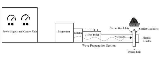
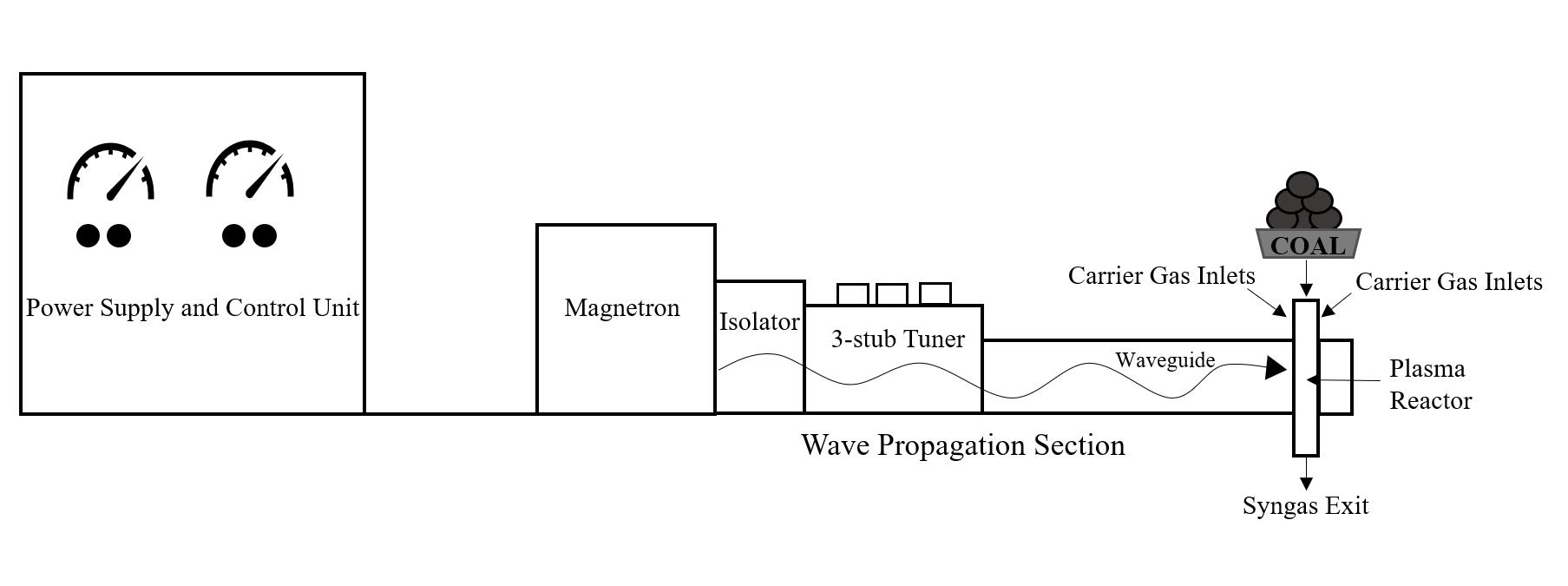
3.1. EMIPG System Physical Description

The setup for an EMIPG system can be divided into five distinct sections: power supply and microwave source, wave propagation section, plasma reactor, carrier gas/feedstock inputs, and data collection equipment. A schematic representation of these basic elements assembled into a system is shown in Figure 2.
Microwaves are generated by a magnetron that operates at a specific frequency and power setting. The typical power setting found within the reviewed literature for an EMIPG system ranges from 0.8 kW to 6 kW. The typical frequency that the magnetron within an EMIPG system operates at is 2.45 GHz. This frequency of 2.45 GHz is normally used at the experimental scale, as it is also the operating frequency of most domestic microwave ovens [23]. A commonly used waveguide for an EMIPG system is the WR-340. The WR-340 is a hollow, rectangular metal waveguide that transports the electromagnetic energy created by the magnetron to the reactor in a single dimension [24]. Some EMIPG setups include an isolator and/or three-stub tuner along the wave propagation section of the system. A three-stub tuner can significantly improve efficiency as it is able to maximize the electric field from the point of generation to the distance of the reactor, substantially reducing reflected power within the system [25]. An isolator assists in protecting the magnetron from damage that can be caused by reflected microwaves [26,27]. The reactor, various carrier gases, and other inputs that are fed into said reactor will be discussed further in the next section. Mass flow controllers (MFC) are used to govern the flow of carrier gases, plasma-forming gases, and aerosolized feedstocks into the reactor of an EMIPG system.
Additionally, data collection equipment can be combined within an EMIPG system in order to follow the syngas as it exits to identify its composition. Some examples of data collection equipment within the EMIPG system are thermocouples, both R-type and K-type, and CCD cameras. Examples of data collection equipment that may be used to analyze the chemical composition of the syngas matrix are gas chromatographs (GC), emission spectroscopy systems (ES), and Fourier-transform infrared spectroscopy (FTIR) systems. Further details pertaining to EMIPG systems within their respective literature are located in Table 2.

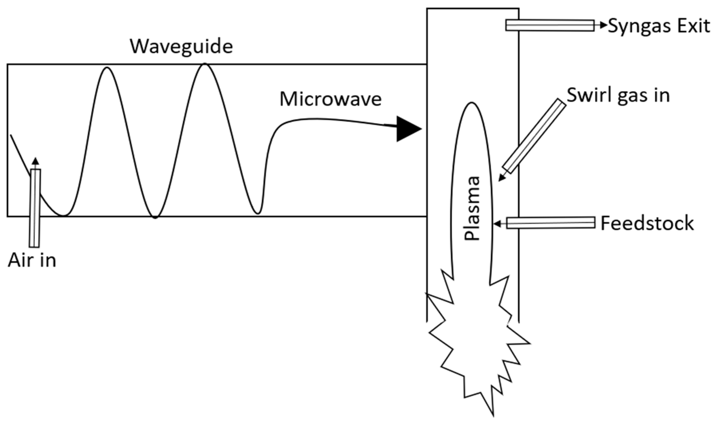
3.2. EMIPG Reactor Physical Description

The typical reactor within an EMIPG system consists of a hollow quartz tube with a specific length and diameter. A breakdown of reactors within EMIPG system reactors and their distinctive physical parameters from the literature review can be found in Table 3. Quartz is commonly used as the material of choice in an EMIPG system reactor for its ability to withstand a wide range of pressure and temperature conditions, as well as its ability to minimally contaminate the product syngas [39]. The reviewed literature shows that the temperature of the plasma flame and the reacting species within the quartz reactor can reach as high as 6100 K. The pressure within all reviewed EMIPG reactor systems remained at an atmospheric level. Most of the feedstocks used within EMIPG systems were simple organic compounds such as methanol, ethanol, and coal. The EMIPG systems that did not use any solid feedstocks or organic compounds were focused on optimizing the plasma flame or observing how different gases can be processed into a useful syngas. Therefore, the only inputs into the reactor of these EMIPG systems are from carrier gases and plasma-forming fluids in order to create and sustain a plasma flame. AC and DC plasma gasification systems have been used at a large industrial scale to safely process MSW, biomass, tires, plastics, hazardous wastes, and refuse-derived fuel (RDF) [40].
Other inputs into an EMIPG system reactor are carrier gases and plasma-forming gases. Carrier gases accompany the feedstock into the reactor and are typically related to the feedstock input by a ratio. Carrier gases typically consist of air, oxygen (O2), and steam (H2O). The carrier gases can be tangentially injected into the reactor, allowing them to act as a physical insulator of the quartz reactor by stabilizing and centering the plasma flame within it [35]. Carrier gasses can have additional benefits by affecting the chemical kinetics within the reactor.
Plasma-forming gases typically consist of nitrogen (N2) or argon (Ar), as they are able to populate the reactor chamber with high-energy electrons that support a more efficient and higher temperature plasma flame [41]. The majority of the EMIPG systems use a tungsten rod that is inserted into the reactor to initiate the plasma flame and then quickly withdrawn from it. This process has been conducted both mechanically and manually within the reviewed literature. The tungsten rod acts as a temporary electrode, and its properties, particularly its high-temperature resistance, make it well suited for the environment within the EMIPG reactor [42]. Other EMIPG systems start the plasma flame within the reactor by introducing a partially ionized plasma-forming gas that is able to support the plasma arc, free from physical electrodes [43]. The downside of this process is that the EMIPG setup will require external equipment that provides excitation energy to the plasma-forming gas by partially ionizing it before it enters the reactor. The equipment used as a source of ionization to the plasma-forming gas is also used in laboratory environments that have inductively coupled plasma (ICP) spectroscopy systems [44].

3.3. Reaction Kinetics within an EMIPG Reactor

A close-up schematic of an EMIPG system reactor and how all of its different components interact is shown in Figure 3. The basic components that make up an EMIPG system reactor include the microwave, which is transferred within a waveguide, the reactor, the input gas, and the feedstock (waste stream). When the feedstock meets the plasma flame, it is converted into a syngas and rises out of the syngas exit to be collected. Feedstock that is not fully combusted falls out of the reactor and is collected as char or ash. Systems that utilize an input gas generally place it above the feedstock entrance so that the entire residence time of the feedstock in the reactor is influenced by it.
The high heating of feedstock and the heat transfer rates within an EMIPG system reactor are described by a process known as fast pyrolysis [45]. The temperature within an EMIPG reactor can exceed 6000 K. Besides the heat transfer within an EMIPG system reactor, a variety of other fluctuating factors determine the overall kinetic reaction that takes place within it to yield a syngas output. These factors include turbulence discrepancies and the rates and respective concentrations of the feedstock, carrier gas, and plasma-forming gas inputs. System variances such as geometry, power source, part and build quality, use of water cooling, and other implemented efficiencies can also affect the reaction kinetics within an EMIPG system reactor. In their research, Yoon et al. used an EMIPG system to compare how different rates and concentrations of input gases, as well as feedstock, can affect the plasma flame and resulting output syngas composition. The research conducted by Yoon et al. explored the effects of O2-to-feedstock ratio, steam-to-fuel ratio, microwave power, rate of feedstock input, and ways to promote gasification efficiency of the EMIPG system. The H2 portion of the syngas linearly decreased as the rate of O2 was increased relative to the rate of the feedstock into the reactor [30,31,46]. CO and CO2 remained relatively constant in the output syngas until the O2-to-feedstock ratio reached 0.6 [30,31,46]. Following a 0.6 O2 to feedstock ratio, CO decreased in the syngas mixture, and CO2 rapidly increased [30,31,46]. Overall, greater O2 presence within the reactor increased the reaction temperature within it [30,31,46]. The increased temperature promoted a greater flow velocity within the reactor, which yielded less efficiency as the feedstock retention time (FRT) within the reactor was reduced [30,31,46]. A 2017 study concluded that FRT within the reactor of an MW discharge plasma gasification system is a key parameter affecting the gasification performance and overall efficiency of the system [17]. Yoon et al. also observed the impact of the steam-to-feedstock ratio within an EMIPG system reactor. The research concluded that both H2 and CO2 content of the resulting syngas increased as the ratio of steam to feedstock increased [30,31,46]. Alternatively, CO content decreased as the steam-to-feedstock ratio increased [30,31,46]. Ultimately, the decrease in the CO content and the resulting heating value of the syngas was found to control the syngas efficiency [30,31,46]. Furthermore, the research found that gasification efficiency was supported by the temperature, length of the plasma flame, and the FRT within the reactor [30,31,46]. The microwave power setting helped to improve combustible gas content, syngas heating value, gas yield, conversion rate, and overall efficiency [30,31,46]. Additionally, an excessive rate of feedstock input would lower the reactor temperature, causing a poor syngas yield [30,31,46]. It is important to note that the feedstock used within the Yoon et al. research was limited to coal and glycerol; regardless, their research still serves as a great foundation for informing numerical modeling with this feedstock. All the factors previously discussed that Yoon et al. observed are summarized in Table 4.
Many different chemical reactions take place within an EMIPG reactor. Furthermore, due to the high-temperature nature of a plasma gasification reactor, there are a variety of matter phases across which these reactions take place. Thus, chemical reactions are described as heterogeneous if different matter phases are involved and homogeneous if they happen within a single matter phase. Typical chemical reactions that take place within an EMIPG system reactor are devolatilization, oxidation, water gas, water gas shift, Boudouard, methanation, steam methane reforming, nitrogenous species formation, and sulfur species formation reactions. The stoichiometric reaction chemistry of these reactions is displayed in Table 5. Chemical reaction rates within an EMIPG reactor can be controlled by either the turbulence or the temperature phenomena that are occurring within it [47]. In order to accurately model the reaction kinetics within an EMIPG reactor given the previous scenario, a common method used is the finite rate chemistry/eddy dissipation (FRC/EDM) Model. The FRC/EDM model considers both the Arrhenius and eddy dissipation reaction rates taking place within the reactor and chooses the minimum value of the two contributions in order to establish the reaction rate [48]. The FRC/EDM model as previously described is commonly referred to as the Kobayashi model [49]. Additionally, it is important to consider the devolatilization of organic feedstocks within an EMIPG reactor. Devolatilization drives moisture and volatile matter from the organic feedstock through the heat within the reactor, and it must be considered in order to build an accurate model of the reactor chemistry [48]. Reviewed literature typically used the FRC/EDM model while simultaneously considering devolatilization in modeling the chemical kinetics within a plasma gasification system reactor. These respective articles that modeled the chemistry within plasma reactors are found in Table 6.

3.4. Governing Equations within an EMIPG Reactor

The reaction kinetics discussed previously are mostly governed by both the temperature and turbulence parameters inside the reactor. Turbulence and temperature directly influence the variable velocity fields (gasifier flow phenomena) at high Reynolds numbers and thus affect momentum, energy, species concentration and transport, heat transfer, drag, vorticity distribution, and swirl flows [48]. In order to properly understand which of the two parameters is controlling the reaction kinetics at a given place and time in the reactor, a complex mathematical model must be created. Typical models within the reviewed articles employ the principles of Navier–Stokes equations for mass, momentum, and energy balance, as well as a Reynolds-averaged Navier–Stokes simulation (RANS) model equation for the turbulence in the reactor. In order to simplify the fluid motion within the reactor, the Eulerian–Eulerian approach is commonly used where both the gas and solid phases are combined into a single continuum [55]. This approach is common for plasma gasification systems because the high heat and turbulence within the reactor, as well as the small solid feedstock size and carrier fluid, cause the gas and solid phase flows to behave similarly to each other. The method that is commonly employed to solve the combination of these complex mathematical models is the finite volume method. The finite volume method discretizes the geometry of the reactor by creating a three-dimensional mesh of a specific number of volumes within it. These volumes allow for the mathematical models to be solved within each discrete volume of the mesh and can be pieced together to describe the entirety of the fluid within the reactor. The RANS approach typically employs the standard k-epsilon model for turbulence. This model is widely accepted for plasma reactor modeling due to its low computational cost and accuracy [55]. All models for mass, momentum, energy conservation, and turbulence are defined in Table 7 and Table 8 and were solved using the finite volume method.

3.5. Modeling Tools/Software for an EMIPG Reactor

In the past, researchers of WtE technologies have typically relied on experimental setup to gain an understanding of the multiple physical–chemical phenomena that take place within the system [58]. Fortunately, with the advent of technology, computational power has evolved in parallel with numerical model solver efficiency [59]. Due to the rapid advancement in both computation and calculation capacity, CFD is a tool that can be used to design, optimize, and predict processes within WtE systems [48]. CFD modeling software uses mathematical models to solve complicated partial differential equations of conservation laws for mass, momentum, and energy, as well as their theoretical and empirical correlations [48]. By synthesizing these models, CFD software has the ability to design reactor simulations incorporating structural, thermal, and chemical analysis [60]. Computational software such as Aspen Plus, Aspen HYSYS, and chemCAD have been used within the literature as plasma gasification modeling tools; however, they are limited in their application. The applications of Aspen Plus, Aspen HYSYS, and chemCAD are focused on process simulation and chemical process simulation only [40]. ANSYS Fluent, OpenFoam, and COMSOL Multiphysics software typically allow for a wide application of multiphysics problems. Barracuda is a simulation software that is tailored for fluidized reactor bed simulation and design. ANSYS CFX uses a vertex-centered solver approach within its software which tailors its application more towards CFD problems that apply to turbomachinery. The specifications for each software package are shown in Table 9. CFD modeling provides multiple benefits to simulate an EMIPG system reactor. It allows for the testing of multiple configurations of reactor geometry; the identification of critical variables that affect the process; and the demonstration of velocity vector profiles, average pressure drop curves slopes, and temperature and species profiles. Modeling also prevents expensive and tedious experimentation [48].

4. Forward Look and Conclusions

4.1. Forward Look

MW plasma gasification is limited in nature by the frequency of electromagnetic energy. The magnetron, which is the driving force of electromagnetic energy in the system, is constrained in size, creating difficulty when scaling the system. To overcome this system constraint and still drive an even plasma flame within a large-scale reactor, multiple magnetrons can be used to distribute electromagnetic energy into the reactor. A demonstration of this configuration in a scaled-up unit can be found in research conducted by Uhm et. al. Uhm et al. used two microwave steam-plasma units to provide an even temperature plasma to a large, cylindrical reactor with a diameter of 90 cm and a height of 180 cm. This research utilized low-grade coals for a feedstock and found a cold gas efficiency of hydrogen-rich syngas of 84% [15]. The high efficiency of this system demonstrates the potential of microwave plasma to be scaled in order to convert waste into energy.

4.2. Conclusions

Plasma gasification offers the ability to produce clean energy and destroy hazardous waste. This technology has not matured for commercial WtE applications. This review focused on experimental microwave-induced plasma gasification (EMIPG) system reactors. An EMIPG system is constituted by various components: power supply and microwave source, wave propagation section, plasma reactor, plasma-forming gases, carrier gas, feedstock inputs, and data collection equipment. Various chemical reactions convert feedstock into syngas. The rates of carrier gas and plasma-forming gas inputs, the operational power of the system, and the rate of the feedstock injection affect the chemical reaction kinetics. The temperature and turbulence play a significant role in determining the rate and distribution of these chemical conversions within an EMIPG reactor. The Navier–Stokes equations for mass, momentum, and energy and the k-epsilon model for turbulence are used to describe the fluid motion and temperature within the reactor. Most studies used the Eulerian–Eulerian approach to model the gas and solid phases. Since the complexity of these mathematical models is significant, CFD software is used to solve the models of multiphysics phenomena happening within the reactor. The CFD software solves the mathematical models describing the reactor by using numerical methods such as the finite volume method. A CFD model can allow optimization of the system, as well as a better understanding of how the system converts various feedstocks, such as plastics, electronic wastes, and COVID-19 biomedical waste.

Author Contributions

Conceptualization, O.S. and E.M.; methodology, O.S and E.M.; formal analysis, O.S. and E.M.; writing—original draft preparation, O.S.; writing—review and editing, E.M.; All authors have read and agreed to the published version of the manuscript.

Funding

This research received no external funding.

Institutional Review Board Statement

Not applicable.

Informed Consent Statement

Not applicable.

Conflicts of Interest

The authors declare no conflict of interest.

Disclaimer

The views expressed in this paper are those of the authors and do not reflect the official policy or position of the U.S. Air Force, the U.S. Department of Defense, or the U.S. Government.

References

  1. Menniti, D.; Burgio, A.; Scordino, N. Population growth, sustainable development, energy resources and environmental protection: The nuclear option. In Proceedings of the 2007 IEEE Lausanne POWERTECH, Lausanne, Switzerland, 1–5 July 2007; pp. 1812–1816. [Google Scholar]
  2. Kaza, S.; Yao, L.; Bhada-Tata, P.; Van Woerden, F. WHAT A WASTE 2.0 A Global Snapshot of Solid Waste Management to 2050 OVERVIEW; U.S. Army Research Laboratory: Aldephi, MD, USA, Reprint from Journal of Intelligence Community Research and Development; 21 September 2012. [Google Scholar]
  3. Charis, G.; Danha, G.; Muzenda, E.; Muzenda, E.; Patel, B.; Mateescu, C.; Muzenda, E. Waste to Energy Opportunities in Botswana: A Case Study Review. In Proceedings of the 2019 7th International Renewable and Sustainable Energy Conference, IRSEC 2019, Agadir, Morocco, 27–30 November 2019; Institute of Electrical and Electronics Engineers Inc.: Piscataway, NJ, USA, 2019. [Google Scholar]
  4. Frimpong, S. Global Energy Security: The Case for a Multifaceted Solution Strategy. J. Energy Eng. 2008, 134, 109–110. [Google Scholar] [CrossRef]
  5. Shittu, O.S.; Williams, I.D.; Shaw, P.J. Global E-waste management: Can WEEE make a difference? A review of e-waste trends, legislation, contemporary issues and future challenges. Waste Manag. 2021, 120, 549–563. [Google Scholar] [CrossRef]
  6. Haque, M.S.; Uddin, S.; Sayem, S.M.; Mohib, K.M. Coronavirus disease 2019 (COVID-19) induced waste scenario: A short overview. J. Environ. Chem. Eng. 2021, 9, 104660. [Google Scholar] [CrossRef]
  7. US Department of Defense. Task Force on Energy Systems for Forward/Remote Operating Bases; US Department of Defense: Washington, DC, USA, 2016.
  8. Meier, A.; Shah, M.; Engeling, K.; Quinn, K. Demonstration of Plasma Assisted Waste Conversion to Gas. In Proceedings of the 49th International Conference on Environmental Systems, Boston, MA, USA, 7–11 July 2019; pp. 1–13. [Google Scholar]
  9. Tang, L.; Huang, H.; Hao, H.; Zhao, K. Development of plasma pyrolysis/gasification systems for energy efficient and environmentally sound waste disposal. J. Electrostat. 2013, 71, 839–847. [Google Scholar] [CrossRef]
  10. Perkins, G. Production of electricity and chemicals using gasification of municipal solid wastes. In Waste Biorefinery; Elsevier: Amsterdam, The Netherlands, 2020; pp. 3–39. [Google Scholar]
  11. Blaisi, N.I.; Roessler, J.G.; Watts, B.E.; Paris, J.; Ferraro, C.C.; Townsend, T.G. Construction material properties of high temperature arc gasification slag as a portland cement replacement. J. Clean. Prod. 2018, 196, 1266–1272. [Google Scholar] [CrossRef]
  12. Arena, U. Process and technological aspects of municipal solid waste gasification. A review. Waste Manag. 2012, 32, 625–639. [Google Scholar] [CrossRef] [PubMed]
  13. Breeze, P. Advanced Waste-to-Energy Technologies. In Energy from Waste; Elsevier: Amsterdam, The Netherlands, 2018; pp. 65–75. [Google Scholar]
  14. Sekiguchi, H.; Orimo, T. Gasification of polyethylene using steam plasma generated by microwave discharge. Thin Solid Films 2004, 457, 44–47. [Google Scholar] [CrossRef]
  15. Uhm, H.S.; Na, Y.H.; Hong, Y.C.; Shin, D.H.; Cho, C.H. Production of hydrogen-rich synthetic gas from low-grade coals by microwave steam-plasmas. Int. J. Hydrogen Energy 2014, 39, 4351–4355. [Google Scholar] [CrossRef]
  16. Sanlisoy, A.; Carpinlioglu, M.O. A review on plasma gasification for solid waste disposal. Int. J. Hydrogen Energy 2017, 42, 1361–1365. [Google Scholar] [CrossRef]
  17. Ho, G.S.; Faizal, H.M.; Ani, F.N. Microwave induced plasma for solid fuels and waste processing: A review on affecting factors and performance criteria. Waste Manag. 2017, 69, 423–430. [Google Scholar] [CrossRef] [PubMed]
  18. Delikonstantis, E.; Sturm, G.; Stankiewicz, A.I.; Bosmans, A.; Scapinello, M.; Dreiser, C.; Lade, O.; Brand, S.; Stefanidis, G.D. Biomass gasification in microwave plasma: An experimental feasibility study with a side stream from a fermentation reactor. Chem. Eng. Process. Process Intensif. 2019, 141, 107538. [Google Scholar] [CrossRef]
  19. Wu, T.N. Environmental perspectives of microwave applications as remedial alternatives: Review. Pract. Period. Hazardous Toxic Radioact. Waste Manag. 2008, 12, 102–115. [Google Scholar] [CrossRef] [Green Version]
  20. Munir, M.T.; Mardon, I.; Al-Zuhair, S.; Shawabkeh, A.; Saqib, N.U. Plasma gasification of municipal solid waste for waste-to-value processing. Renew. Sustain. Energy Rev. 2019, 116, 109461. [Google Scholar] [CrossRef]
  21. Saleem, F.; Harris, J.; Zhang, K.; Harvey, A. Non-thermal plasma as a promising route for the removal of tar from the product gas of biomass gasification—A critical review. Chem. Eng. J. 2020, 382, 122761. [Google Scholar] [CrossRef]
  22. Saleem, F.; Rehman, A.; Abbas, A.; Hussain Khoja, A.; Ahmad, F.; Liu, L.; Zhang, K.; Harvey, A. A comparison of the decomposition of biomass gasification tar compound in CO, CO2, H2 and N2 carrier gases using non-thermal plasma. J. Energy Inst. 2021, 97, 161–168. [Google Scholar] [CrossRef]
  23. Dharmaraj, S.; Ashokkumar, V.; Pandiyan, R.; Halimatul Munawaroh, H.S.; Chew, K.W.; Chen, W.H.; Ngamcharussrivichai, C. Pyrolysis: An effective technique for degradation of COVID-19 medical wastes. Chemosphere 2021, 275, 130092. [Google Scholar] [CrossRef] [PubMed]
  24. Chicone, C. Problems and Projects: Waveguides, Lord Kelvin’s Model. In An Invitation to Applied Mathematics; Elsevier: Amsterdam, The Netherlands, 2017; pp. 775–791. [Google Scholar]
  25. Hong, Y.C.; Lee, S.J.; Shin, D.H.; Kim, Y.J.; Lee, B.J.; Cho, S.Y.; Chang, H.S. Syngas production from gasification of brown coal in a microwave torch plasma. Energy 2012, 47, 36–40. [Google Scholar] [CrossRef]
  26. Ellison, C.R.; Hoff, R.; Mărculescu, C.; Boldor, D. Investigation of microwave-assisted pyrolysis of biomass with char in a rectangular waveguide applicator with built-in phase-shifting. Appl. Energy 2020, 259, 114217. [Google Scholar] [CrossRef]
  27. Sun, H.; Lee, J.; Bak, M.S. Experiments and modeling of atmospheric pressure microwave plasma reforming of a methane-carbon dioxide mixture. J. CO2 Util. 2021, 46, 101464. [Google Scholar] [CrossRef]
  28. Vecten, S.; Wilkinson, M.; Martin, A.; Dexter, A.; Bimbo, N.; Dawson, R.; Herbert, B. Experimental study of steam and carbon dioxide microwave plasma for advanced thermal treatment application. Energy 2020, 207, 118086. [Google Scholar] [CrossRef]
  29. Vecten, S.; Wilkinson, M.; Bimbo, N.; Dawson, R.; Herbert, B.M.J. Experimental investigation of the temperature distribution in a microwave-induced plasma reactor. Fuel Process. Technol. 2021, 212, 106631. [Google Scholar] [CrossRef]
  30. Yoon, S.J.; Lee, J.G. Syngas Production from Coal through Microwave Plasma Gasification: Influence of Oxygen, Steam, and Coal Particle Size. Energy Fuels 2011, 26, 524–529. [Google Scholar] [CrossRef]
  31. Yoon, S.J.; Yun, Y.M.; Seo, M.W.; Kim, Y.K.; Ra, H.W.; Lee, J.G. Hydrogen and syngas production from glycerol through microwave plasma gasification. Int. J. Hydrogen Energy 2013, 38, 14559–14567. [Google Scholar] [CrossRef]
  32. Shin, D.H.; Hong, Y.C.; Lee, S.J.; Kim, Y.J.; Cho, C.H.; Ma, S.H.; Chun, S.M.; Lee, B.J.; Uhm, H.S. A pure steam microwave plasma torch: Gasification of powdered coal in the plasma. Surf. Coat. Technol. 2013, 228, S520–S523. [Google Scholar] [CrossRef]
  33. Su, L.; Kumar, R.; Ogungbesan, B.; Sassi, M. Experimental investigation of gas heating and dissociation in a microwave plasma torch at atmospheric pressure. Energy Convers. Manag. 2014, 78, 695–703. [Google Scholar] [CrossRef]
  34. Lin, K.C.; Lin, Y.C.; Hsiao, Y.H. Microwave plasma studies of Spirulina algae pyrolysis with relevance to hydrogen production. Energy 2014, 64, 567–574. [Google Scholar] [CrossRef]
  35. Tsai, C.H.; Chen, K.T. Production of hydrogen and nano carbon powders from direct plasmalysis of methane. Int. J. Hydrogen Energy 2009, 34, 833–838. [Google Scholar] [CrossRef]
  36. Wang, Y.F.; You, Y.S.; Tsai, C.H.; Wang, L.C. Production of hydrogen by plasma-reforming of methanol. Int. J. Hydrogen Energy 2010, 35, 9637–9640. [Google Scholar] [CrossRef]
  37. Sturm, G.S.J.; Munoz, A.N.; Aravind, P.V.; Stefanidis, G.D. Microwave-Driven Plasma Gasification for Biomass Waste Treatment at Miniature Scale. IEEE Trans. Plasma Sci. 2016, 44, 670–678. [Google Scholar] [CrossRef] [Green Version]
  38. Hrycak, B.; Czylkowski, D.; Miotk, R.; Dors, M.; Jasinski, M.; Mizeraczyk, J. Application of atmospheric pressure microwave plasma source for hydrogen production from ethanol. Int. J. Hydrog. Energy 2014, 39, 14184–14190. [Google Scholar] [CrossRef]
  39. Su, X.; Jin, H.; Guo, L.; Guo, S.; Ge, Z. Experimental study on Zhundong coal gasification in supercritical water with a quartz reactor: Reaction kinetics and pathway. Int. J. Hydrogen Energy 2015, 40, 7424–7432. [Google Scholar] [CrossRef]
  40. Chanthakett, A.; Arif, M.T.; Khan, M.M.K.; Oo, A.M.T. Performance assessment of gasification reactors for sustainable management of municipal solid waste. J. Environ. Manag. 2021, 291, 112661. [Google Scholar] [CrossRef]
  41. Okino, A.; Miyahara, H.; Yabuta, H.; Mizusawa, Y.; Doi, T.; Watanabe, M.; Hotta, E. Development of a new multi-plasma gas inductively coupled plasma torch. In Proceedings of the IEEE International Conference on Plasma Science, Baltimore, MD, USA, 1 July 2004; p. 306. [Google Scholar]
  42. Pintsuk, G.; Hasegawa, A. Tungsten as a Plasma-Facing Material. In Comprehensive Nuclear Materials; Elsevier: Amsterdam, The Netherlands, 2020; pp. 19–53. [Google Scholar]
  43. Ebeling, W. Coulomb interaction and ionization equilibrium in partially ionized plasmas. Physica 1969, 43, 293–306. [Google Scholar] [CrossRef]
  44. Makonnen, Y.; Beauchemin, D. The inductively coupled plasma as a source for optical emission spectrometry and mass spectrometry. In Sample Introduction Systems in ICPMS and ICPOES; Elsevier: Amsterdam, The Netherlands, 2020; pp. 1–55. [Google Scholar]
  45. Pattiya, A. Direct Thermochemical Liquefaction for Energy Applications Fast Pyrolysis; Woodhead Publishing: Sawston, UK, 2018. [Google Scholar] [CrossRef]
  46. Yoon, S.J.; Lee, J.G. Hydrogen-rich syngas production through coal and charcoal gasification using microwave steam and air plasma torch. Int. J. Hydrog. Energy 2012, 37, 17093–17100. [Google Scholar] [CrossRef]
  47. Ibrahimoglu, B.; Cucen, A.; Yilmazoglu, M.Z. Numerical modeling of a downdraft plasma gasification reactor. Int. J. Hydrogen Energy 2017, 42, 2583–2591. [Google Scholar] [CrossRef]
  48. Silva, V.B.R.E.; Cardoso, J. Introduction and overview of using computational fluid dynamics tools. In Computational Fluid Dynamics Applied to Waste-to-Energy Processes; Elsevier: Amsterdam, The Netherlands, 2020; pp. 3–28. [Google Scholar]
  49. Kobayashi, H.; Howard, J.B.; Sarofim, A.F. Coal devolatilization at high temperatures. Symp. Combust. 1977, 16, 411–425. [Google Scholar] [CrossRef]
  50. Kuo, P.C.; Illathukandy, B.; Wu, W.; Chang, J.S. Plasma gasification performances of various raw and torrefied biomass materials using different gasifying agents. Bioresour. Technol. 2020, 314, 123740. [Google Scholar] [CrossRef]
  51. Park, D.C.; Day, S.J.; Nelson, P.F. Formation of N-containing gas-phase species from char gasification in steam. Fuel 2008, 87, 807–814. [Google Scholar] [CrossRef]
  52. Gai, C.; Dong, Y.; Zhang, T. Distribution of sulfur species in gaseous and condensed phase during downdraft gasification of corn straw. Energy 2014, 64, 248–258. [Google Scholar] [CrossRef]
  53. Kuo, P.C.; Wu, W.; Chen, W.H. Gasification performances of raw and torrefied biomass in a downdraft fixed bed gasifier using thermodynamic analysis. Fuel 2014, 117, 1231–1241. [Google Scholar] [CrossRef]
  54. Ibrahimoglu, B.; Yilmazoglu, M.Z. Numerical modeling of a downdraft plasma coal gasifier with plasma reactions. Int. J. Hydrogen Energy 2020, 45, 3532–3548. [Google Scholar] [CrossRef]
  55. Silva, V.B.R.E.; Cardoso, J. How to approach a real CFD problem—A decision-making process for gasification. In Computational Fluid Dynamics Applied to Waste-to-Energy Processes; Elsevier: Amsterdam, The Netherlands, 2020; pp. 29–83. [Google Scholar]
  56. Badzioch, S.; Hawksley, P.G.W. Kinetics of Thermal Decomposition of Pulverized Coal Particles. Ind. Eng. Chem. Process Des. Dev. 1970, 9, 521–530. [Google Scholar] [CrossRef]
  57. Fan, F.; Wang, S.; Yang, S.; Hu, J.; Wang, H. Numerical investigation of gas thermal property in the gasification process of a spouted bed gasifier. Appl. Therm. Eng. 2020, 181, 115917. [Google Scholar] [CrossRef]
  58. Couto, N.; Silva, V.B.; Bispo, C.; Rouboa, A. From laboratorial to pilot fluidized bed reactors: Analysis of the scale-up phenomenon. Energy Convers. Manag. 2016, 119, 177–186. [Google Scholar] [CrossRef]
  59. Couto, N.; Silva, V.; Monteiro, E.; Teixeira, S.; Chacartegui, R.; Bouziane, K.; Brito, P.S.D.; Rouboa, A. Numerical and experimental analysis of municipal solid wastes gasification process. Appl. Therm. Eng. 2015, 78, 185–195. [Google Scholar] [CrossRef]
  60. Reactor Design & Simulation | Ansys. Available online: https://www.ansys.com/solutions/solutions-by-industry/materials-and-chemical-processing/reactor-design (accessed on 22 February 2021).
  61. Thompson, M.K.; Thompson, J.M. Introduction to ANSYS and Finite Element Modeling. In ANSYS Mechanical APDL for Finite Element Analysis; Elsevier: Amsterdam, The Netherlands, 2017; pp. 1–9. [Google Scholar]
  62. About Ansys. Available online: https://www.ansys.com/about-ansys (accessed on 22 February 2021).
  63. Liu, T.; Zhao, D. Numeric simulation and analysis of H 2-O 2 premixed combustion based on OpenFOAM. In Proceedings of the 2012 IEEE Symposium on Robotics and Applications, ISRA 2012, Kuala Lumpur, Malaysia, 3–5 June 2012; pp. 27–30. [Google Scholar]
  64. OpenFOAM. Available online: https://www.openfoam.com/ (accessed on 18 May 2021).
  65. Ansys CFX | Industry-Leading CFD Software. Available online: https://www.ansys.com/products/fluids/ansys-cfx (accessed on 18 May 2021).
  66. Barbu, B.; Iturregi, A.; Berger, F.; Torres, E. Numerical analysis of the electric arc simulation using ansys CFX. In IET Conference Publications; IET: London, UK, 2012; Volume 2012, pp. 311–316. [Google Scholar]
  67. Yadav, H.N.S.; Kumar, M.; Kumar, A.; Das, M. COMSOL simulation of microwave plasma polishing on different surfaces. Mater. Today Proc. 2021. [Google Scholar] [CrossRef]
  68. COMSOL Multiphysics® Software–Understand, Predict, and Optimize. Available online: https://www.comsol.com/comsol-multiphysics (accessed on 18 May 2021).
  69. Krusch, S.; Scherer, V.; Solimene, R.; Senneca, O. Assessment of coal pyrolysis kinetics for Barracuda or Ansys Fluent. Energy Procedia 2019, 158, 1999–2004. [Google Scholar] [CrossRef]
  70. Research and General Fluidization|CPFD Software. Available online: https://cpfd-software.com/applications/general-fluidization/ (accessed on 18 May 2021).
Figure 1. Classifications of plasma gasification systems.
Gases 01 00011 g001
Figure 2. Schematic representation of a basic EMIPG system.
Gases 01 00011 g002
Figure 3. Close-up schematic representation of an EMIPG system reactor.
Gases 01 00011 g003
Table 1. Advantages of MW plasma gasification systems.
SourceAdvantage
[16]Lower voltage requirement than other plasma generator methods.
[17]Lower setup cost due to its ability to operate under atmospheric conditions, also allowing the system to be much more compact in size.
[16,18]Works without an electrode arrangement so that it avoids operational problems specific to electrode utilization.
[19]Microwave energy has already shown its ability to safely combust a variety of hazardous wastes through previous remedial applications.
Table 2. Major components of experimental MIPG systems.
SourcePower SettingMagnetronWaveguideMFCThree-Stub TunerData Collection EquipmentOther Equipment
[28]1–6 kW2.45 GHz (Sairem GMP G4 60 K T400)WR-340Alicat Scientific, Tucson AZ, USAYes3 thermocouples, HR 2000+ES spectrometer (Ocean Optics Inc., Largo, FL, USA)E-3000 precision steam generators
[29]2–5 kW2.45 GHz (Sairem GMP G4 60 K T400)WR-340Alicat Scientific, Tucson AZ, USAYes4 type K thermocouples, HR2000+ ES spectrometer (Ocean Optics Inc., Largo, FL, USA)E-3000 precision steam generators
[18]Up to 6 kW2.45 GHz (N.S.)WR-340Bronkhorst F-210 AV-50 KN.S.Offline micro-gas chromatograph (micro-GC, Varian CP-4900), sampling bags (Tedlar, 15 L)Impedance tuner, solid feeder
[30,31]1–1.8 kW2.45 GHz (SM 745, Richardson Electronics)N.S.Brooks 5850Yes2 R-type and 5 K-type thermocouples, GC HP 6890, TCD Carbosphere 80/100 packed column, AlltechGlycerol preheater and feeder, steam supplier, gear pump (Cole Parmer, 74014-750), syringe pump, band heater
[25]4 kW2.45 GHz (N.S.)WR-340N.S.YesGas analyzer (N.S.)Quartz plate installed in the end of tapered waveguide
[32]5 kW2.45 GHz (N.S.)Twisted WaveguideN.S.YesGas analyzer (N.S.)Quartz plate installed in the end of tapered waveguide
[33]1.2–1.6 kW2.45 GHz (N.S.)WR-248N.S.YesOptical emission spectroscopy system, transmission stage, optical fiber bundle, spectrometer, CCD camera, data acquisition unitForward and backward power meter controller
[34]0.8, 0.9, and 1 kWNot specifiedN.S.N.S.YesGC/TCD, RGA, ESEM, EA (N.S.)Voltage regulator, cooling water
[35]0.8–1.8 kW2.45 GHz (National Electronics YJ-1600)WR-340N.S.YesGC, FTIRCavity resonator
[36]0.8–1.4 kW2.45 GHz (National Electronics YJ-1600)ASTEX WR-340N.S.YesGC/TCD, FTIR, MSCavity resonator
[37]Up to 6 kW2.45 GHz (N.S.)WR-340Bronkhorst F-201 AV-50 KYesGC, collection bags (N.S.)Variable reflector, Sairem SAS for all microwave circuits, impedance transformer
[38]Up to 6 kW915 MHz, 2.45 GHzWR-975, WR-430N.S. GC (Shimadzu GC-2014 and SRI 8610 C), FTIR (Thermo Nicolet 380), optical emission spectroscopy (CVI DK-480), CCD cameraWater cooling, ferrite circulator with water load, directional coupler, moveable plunger
N.S.: not specified.
Table 3. Reactor description within EMIPG systems.
SourceFeedstockRate of Feedstock InputReactor GeometryOperating PressureCarrier Gases/Plasma-Forming GasesRate of Carrier Gas/Plasma-Forming Gases InputIgnition SourceReactor
Temperature
[28]NoneNoneQuartz tube (L: 450 mm, OD: 25.6 mm, ID: 30 mm)AtmosphericH2O, CO220–50 g/min, 20–80 SLPMInserted tungsten rodUp to 6300 °C
[29]NoneNoneQuartz tube (L: 35 cm, OD: 25.6 mm, ID: 30 mm)AtmosphericH2O, CO2, Air10–50 g/min (up to 200 °C), 0–100 SLPM, 0–100 SLPMInserted tungsten rodUp to 6300 °C
[18]CH1.5O.4909–13 g/sQuartz Tube (L: 50 mm, OD: 34 mm, ID: 30 mm)AtmosphericAir, N28.5–10 NL/min, 17.9–25 NL/minUsed plasma-forming gas (N2)973–2173 K
[30,31]Coal1 g/minQuartz Tube (L:100 cm, ID: 5.8 cm)AtmosphericN2, O2, steam15 L/min, 0–1.0 L/min, 0–1.5 mL/minUsed plasma-forming gas (N2)Above 3000 °C
[31]Glycerol3 g/minQuartz Tube (L:100cm, ID: 5.8 cm)AtmosphericN2, O2, steam15 L/min, 0–2.6 L/min, 0–7.2 mL/minUsed plasma-forming gas (N2)N.S.
[25]Coal0–3.75 kg/hQuartz tube (L: N.S., OD: 30 mm, thickness: 1.5 mm)AtmosphericO2, air20 L/min, 15 L/minInserted tungsten rod2000–6500 K
[32]Coal160 mol coal powder/hQuartz tube (L: N.S., OD: 30 mm, thickness: 1.5 mm)AtmosphericO214 mol/hN.S.5000 °C
[33]NoneNoneQuartz tube (2.54 cm in diameter and 22.5 cm in length)AtmosphericAir, N2, Ar30 L/min-60 L/minInserted tungsten rod5446–6100 K
[34]Spirulina algae1 g of dry Spirulina algaeQuartz tube (L: 35 cm, OD: 3.3 cm, ID: 2.9 cm)AtmosphericN212 L/minN.S.1063–1121 K
[35]CH412–18 SLPMQuartz tube (OD: 3.3 cm)AtmosphericN212–18 SLPMN.S.N.S.
[36]Methanol12.4 SLPMQuartz tube (ID: 2.9 cm)AtmosphericN2N.S.N.S.1500 K
[37]Cellulose0.5 g/sQuartz tube (ID: 31 mm, wall thickness: 2 mm)AtmosphericAir15–20 NL/minInserted ignition electrode system4000–5000 K
[38]EthanolIntroduced into system via bubbler @ 20 °C and 3% v/vQuartz tube (N.S.)AtmosphericCO2, N2, Ar1500–3900 NL/hN.S.Up to 6000 K
N.S.: not specified, L: length, OD: outside diameter, ID: inside diameter, SLPM: standard liter per minute.
Table 4. Reactor kinetic relationships and effects from Yoon et al.’s research.
RelationshipEffect
O2-to-feedstock ratio
  • H2 content in syngas linearly decreased with O2 additions.
  • CO remained constant until O2-to-feedstock ratio reached 0.6 and then decreased.
  • CO2 remained constant until O2-to-feedstock ratio reached 0.6 and then rapidly increased.
  • Increasing the O2-to-feedstock ratio increased the reactor temperature and the CH4 content in the syngas due to the decomposition.
  • Increase in O2 supply increases the reaction temperature, which increases the flow velocity. Therefore, the syngas is less efficient because the FRT is reduced.
Steam-to-feedstock ratio
  • H2 and CO2 content in the syngas increased with the increase in the steam-to-fuel ratio.
  • CO content decreased with the increase in the steam to fuel ratio.
  • Decrease in CO content and the heating value of the syngas leads to the decrease in carbon conversion and cold gas efficiency.
Gasification efficiency
  • Dominated by the temperature, length of the plasma flames, and the FRT.
Microwave power
  • Increase in microwave power improves the combustible gas content, syngas heating value, gas yield, conversion rate, and efficiency.
Rate of feedstock input
  • With glycerol feed rate it was found that an excessive supply would lower the reactor temperature and thus decrease the heating value and production yield of syngas.
Table 5. Key chemical reactions within an EMIPG system reactor [50,51,52,53].
Reaction NameStoichiometric Description
Devolatilization C H x O y N z S w C h a r + V o l a t i l e s
Oxidation C + 0.5 O 2 C O ,   Δ H 0 = 268   kJ   mol 1
C + O 2 C O 2   ,   Δ H 0 = 406   kJ   mol 1
Water gas reaction C + H 2 O C O + H 2   ,   Δ H 0 = 131.4   kJ   mol 1
Water gas shift C O + H 2 O C O 2 + H 2   ,   Δ H 0 = 42   kJ   mol 1
Boudouard C + C O 2 2 C O ,   Δ H 0 = 172.6   kJ   mol 1
Methanation C + 2 H 2 C H 4 ,   Δ H 0 = 75   kJ   mol 1
Steam methane reforming C H 4 + H 2 O C O + 3 H 2 ,   Δ H 0 = 206   kJ   mol 1
Nitrogenous species C h a r N H H C N
H C N + H 2 O N H 3 + C O
Sulfur species H 2 S + C O 2 C O S + H 2 O
H 2 S + C O C O S + H 2
Table 6. Numerical modeling strategies of chemical kinetics within a plasma gasification system reactor.
SourceReactor TypeModeling SoftwareModel UsedDevolatilization ConsideredEquations/Models Implemented
[47]Downdraft Plasma Coal and Biomass Gasifier ReactorANSYS FluentFRC/EDMYesFRC/EDM
Devolatilization: single rate model
[54]Downdraft plasma coal gasifier reactorANSYS FluentFRC/EDMYesFRC/EDM
Devolatilization: single rate model
[55]Pilot-scale plasma bubbling fluidized bed reactorANSYS FluentFRC/EDMYes
FRC/EDM
Devolatilization: user-defined function (UDF) using single rate model developed by Badzioch and Hawsley [56].
[6]Updraft plasma gasifier reactorANSYS FluentFRC/EDMYesFRC/EDM
Devolatilization: UDF
[50]Downdraft plasma gasifier reactorAspen PlusN.S.YesHCOALGEN model: used to estimate the heat of combustion, heat of formation, and heat capacity of feedstock.
DCOALIGT model: used to calculate the density of the feedstock.
[57]Plasma spouted bed gasifierOpenFOAMN.S.YesMultiphase particle-in-cell approach (MPPICFoam)
CoalChemistryFoam
N.S.: not specified.
Table 7. Governing equations within a plasma gasification reactor.
SourceMass Balance ModelMomentum ModelEnergy Conservation ModelTurbulence Model
[55]Solid phase:
t ( α s ρ s ) + · ( α s ρ s v s ) = S s g
Gas phase:
t ( α g ρ g ) + · ( α g ρ g v g ) = S g s
Supporting equations:
S s g = S g s = M c   γ c R c
1 ρ g = R T p i = 1 n Y i M i
Solid phase:
t ( α s ρ s v s ) + · ( α s ρ s v s v s ) = α s · p s + · α s τ ¯ s + α s p s g + β ( v g v s ) + S s g U s
Gas phase:
t ( α g ρ g v g ) + · ( α g ρ g v g v g ) = α g · p g + · α g τ ¯ g + α g p g g + β ( v g v s ) + S g s U s
Gas and solid phases:
t ( α q ρ q h q ) + · ( α q ρ q v q h q ) = α q t ( ρ q ) + τ ¯ q : · v q : · q q + S q + p = 1 n ( Q p q + m ˙ p q h p q m ˙ p q h p q )
Supporting equations:
Q p q = h p q ( T p T q )
h p q = 6 k p α q α p N u q d p 2
N u s = h g s d s k g = ( 7 10 α g + 5 α g 2 ) ( 1 + 0.7 R e s s 0.2 P r g 0.33 ) + ( 1.33 2.4 α g + 1.2 α g 2 ) R e s 0.7 P r g 0.33
k ε model:
t ( ρ k ) + x i ( ρ k u i ) = x j [ ( μ + μ i σ k ) ] + G k + G b ρ ε Y m + S k
t ( ρ ε ) + x i ( ρ ε v i ) = x j [ ( μ + μ i σ ε ) ε x j ] + C 1 ε ε k ( G k + C 3 ε G b ) C 2 ε ρ ε 2 k + S ε
Table 8. Definitions for variables in Table 7.
VariableTermVariableTerm
ρ Density τ ¯ g Gas-phase stress tensor
v Instantaneous velocity of gas/solid phase β Gas–solid interphase drag coefficient
s Solid-phase subscript U s Mean velocity of solid
g Gas-phase subscript G k Generation of turbulence kinetic energy due to the mean velocity gradients
SMass source term G b Generation of turbulence kinetic energy due to buoyancy
R c Reaction rate Y m Contribution of fluctuating dilatation in compressible turbulence to the overall dissipation rate
γ c Stoichiometric coefficient S ε User-defined source term
M c Molecular weight S k User-defined source term
RUniversal gas constant Q p q Heat transfer intensity between fluid phase p and solid phase q
T Temperature of gas mixture q q Heat flux
p Gas pressure S q Source term due to chemical reactions
Y i Mass fraction h p q Enthalpy of the interface
M i Molecular weight of each species k p Thermal conductivity for phase p
R e s Reynolds number based on diameter of solid phase and relative velocity P r g Prandtl number of the gas phase
Table 9. Comparison of CFD modeling software packages.
SourcesCFD SoftwareDeveloperQuick Specifications
[55,61,62]FluentANSYS
  • FRC/EDM model which directly applies to a plasma reactor system
  • Allows for user-defined functions to be created but has built-in modules for dealing with reactor phenomena
  • Built-in modules for chemical species descriptions and functions
  • Can be used for a wide array of multiphysics problems
  • Tested and verified readily available models
  • Cell-centered approach allows for low computational energy in mass, momentum, and energy conservation models
  • Has been used to model MW plasma and other plasma reactors
[55,63,64]OpenFoam Open CFD Ltd.
  • Free, open source solver platform allows for synthesis of different solver methods
  • Can be used for a wide array of multiphysics problems
  • Independently tested, released every six months
  • Has been used to model plasma gasification reactors, but requires user-defined functions.
[55,65,66]CFXANSYS
  • Industry-leading CFD software for turbomachinery applications
  • Can be used for a wide array of multiphysics problems
  • Vertex-centered approach
  • Not suitable for plasma reactor modeling
[55,67,68]COMSOL MultiphysicsCOMSOL Inc.
  • Can be used for a wide array of multiphysics problems
  • Software designed for simulations in all fields of scientific study.
  • Allows for solutions that deal with electrical, structural, acoustics, fluid, heat, and chemical disciplines
  • Has been used extensively in modeling MW plasma and other plasma reactors
[55,69,70]BarracudaCPFD Software LLC.
  • Good for industrial-scale simulations
  • Designed for applications like fluidized bed operation and design
  • Deals exclusively with gas-particle fluidized reactors
  • Not suitable for modeling an EMIPG system
Publisher’s Note: MDPI stays neutral with regard to jurisdictional claims in published maps and institutional affiliations.

