1. Introduction
Climate change is one of the most pressing issues facing humanity today. As the Earth’s temperature continues to rise, the need for efficient and sustainable mobility solutions becomes increasingly urgent [
1]. One potential solution is the use of battery electric vehicles (BEVs), which offer an emission-free and efficient alternative to traditional fossil fuel-powered vehicles, since they emit the lowest amount of greenhouse gases during their lifetime compared to other propulsion concepts [
2].
Since BEVs often include larger and more powerful battery packs compared to conventional grid-tied energy storage systems, they offer new possibilities for energy and power distribution [
3,
4]. Additionally, passenger cars are usually utilized less than 1
per day on average. In order to leverage the ecological and economic benefits, the unused batteries could be used for grid stabilization purposes in the meantime [
5].
In recent years, researchers have begun to explore the potential for bidirectional charging in BEVs. This technology allows BEVs to not only draw electric power from the grid to recharge their batteries, but also to supply power back to the grid when needed. Thereby, the power grid can be stabilized and peak shaving is possible. Usually, this is performed by the vehicles’ onboard charger (OBC), since grid-parallel power flow is only possible via an alternating current connection not provided by the traction battery. Therefore, previous studies focused mainly on the technical aspects of bidirectional converters. Currently, AC charging is possible up to 43
for BEVs [
6,
7]. AC discharging from BEVs into the power grid, however, is mostly only possible in single-phase up to a power rate of
[
8]. Since the high-voltage (HV) batteries implemented in BEVs are generally able to discharge faster than they can be charged, a great amount of grid stabilizing potential is still unused [
9].
In this paper, a new approach of bidirectional charging utilizing multilevel inverter (MLI) systems is presented. By using a reconfigurable battery system (RBS) based on the modular MLI first published in [
10] and adapted for batteries as energy storage in [
11,
12,
13], bidirectional charging in a grid-connected scenario can be performed. In contrast to the state-of-the-art and recent research, the approach described in this paper is theoretically able to discharge the battery with the full system power available at any time [
14,
15]. Additionally, in contrast to [
16], no additional H-bridge converter is necessary within the system. By being based on an MLI system, the proposed approach also has more degrees of freedom for current control compared to [
17].
2. Materials and Methods
In this section, a brief introduction to battery-based modular MLIs is given. Additionally, bidirectional charging with an RBS in BEV application is described. Furthermore, the fundamentals of a proportional-resonant (PR) controller, which is used for grid-parallel operation of the system, are described.
2.1. Modular Multilevel Inverters
Generally, an MLI is a type of power inverter that produces an output voltage waveform with multiple levels. These levels can be achieved by using multiple sources of direct current (DC) voltage [
18]. A modular MLI, in addition, is built from multiple modules containing a power system. These modules can be freely adjusted in quantity and design, giving the possibility to assemble an electric power system with more degrees of freedom. As a result, highly-efficient systems can be obtained with little effort. Another advantage of using a (modular) MLI over state-of-the-art two-level inverters is an increased quality of the output waveform with less total harmonic distortion (THD). This results in notable cost, weight and size savings, e.g., through mitigation of the current filters.
Currently, MLIs are usually used in power transmission systems by using capacitors as energy storage [
19,
20]. However, it is possible to use lithium-ion batteries as energy storage as well, so that the MLI acts as an RBS and additionally includes a battery management system (BMS) as described in [
13].
By implementing proactive balancing strategies for the modular multilevel concept, significant stress mitigation for the battery cells, as well as extended vehicle range and battery lifetime can be achieved [
21,
22,
23]. On the same token, MLIs natively include the functionalities required for bidirectional charging, as described in the following.
2.2. Bidirectional Charging for Battery Electric Vehicles
Vehicle-to-Grid (V2G) is a technology used in cars in order to charge HV batteries of a car from the grid or vice versa to transfer energy from the vehicle to the grid via the same charging interface. This is often referred to as bidirectional charging. In conventional BEVs, a bidirectional OBC is usually built as a two-stage bidirectional AC–DC converter [
24]. The primary stage is directly connected to the battery pack, while the secondary stage is connected to the power grid via a full-bridge AC–DC converter. It is responsible for current wave shaping and power factor correction (PFC). Since the full-bridge AC–DC converter needs to be built from active switches to be bidirectional, a single inductor can be used for PFC in this case. For electrical safety reasons, a galvanically isolated DC–DC converter builds the interconnection between the primary and secondary stages. For this purpose, a classic buck-boost converter or a dual-active bridge (DAB) are considered. The topology, including the DAB, is more expensive but reduces the amount of low-frequency ripples in the secondary DC-link as well as the capacitor size. In this case, the secondary DC-link voltage is regulated by the DAB [
24,
25]. A conventional bidirectional OBC is depicted schematically in
Figure 1.
Through the increased utilization of BEV traction batteries for tasks other than vehicle operation and propulsion, consumers may fear a shorter battery lifetime and overall shorter vehicle life. Bidirectional charging could indeed lead to a significantly shorter vehicle lifetime due to increased battery ageing. Therefore, the effect of bidirectional charging has been intensively researched by several studies. While Dubarry, et al. [
26] concludes that bidirectional charging increases the battery ageing speed by up to 75% in a V2G scenario, where two equivalent full cycles per day are achieved, Schwenk, et al. [
27] states that up to 28% faster battery ageing can be expected in an undefined scenario. However, overall battery lifetime of BEVs is expected to be significantly higher than most manufacturers’ warranties. For instance, findings published in [
28] conclude that even with the high additional battery ageing through V2G operation, the total lifetime of a BEV will match the lifetime of conventional vehicles. Nevertheless, consumers could earn back the expenses caused by faster battery degradation through bidirectional charging services, since grid stabilization services are usually well paid by grid operators.
2.3. Grid-Parallel Control of an RBS Using a PR Controller
In contrast to conventional BEVs, in a BEV with an MLI-based RBS, the OBC can be omitted since the system can produce any voltage level below the maximum pack voltage at any time. Additionally, with an RBS, it is expected that battery degradation is reduced overall by the pulsed (dis-) charging currents [
29]. Bidirectional AC charging with an RBS is similar to regenerative braking. This term refers to the electric machine’s operation when a negative torque is controlled to slow down the vehicle and recharge the batteries by using the back electromagnetic force of the electric motor.
Independently of the implemented hardware, there are two different operating strategies used to control bidirectional charging. The first option is based on a separated task for grid synchronization and a proportional-integral (PI) controller for current control. The usage of a PI controller is only feasible with a Clarke and Park transformation for grid-tied systems. Consequently, a rotating coordinate system with
and
axes is introduced. The phase angle is estimated by a phase-locked loop (PLL) in order to achieve grid synchronization. The PLL is usually implemented either as a hardware component or as a software module within the control code. The received phase response is used as a reference to the voltage output. The PI controller’s transfer function for the
and
coordinate system is given by
with the proportional and integral amplifications
and
, respectively. Voltage distortions significantly reduce this control method’s performance. Furthermore, the necessary compensation techniques are very sensitive to a limit in processing performance. To solve these problems, the second option, comprised of a PR controller, can be used to operate the RBS. The PR controller is based on the concept proposed in [
30] and further used in [
31,
32,
33]. The implementation is partly taken over from [
34], where preliminary investigations were performed and adapted as well as enhanced at operating speed.
A PR controller comprises two components: a proportional gain
and a resonant gain
. While the proportional gain serves the same purpose as in a PI controller, the resonant gain is adjusted to match the desired AC frequency
. This controller is then used to counter other harmonic vibrations. As a result, the overall transfer function of the controller is characterized as
Through an expansion of the resonant term with
the other harmonics
h such as the third, fifth or seventh can be controlled or mitigated. The grid synchronization is performed through a state-space conversion of the grid voltage
, described by
Corresponding to a power factor (PF) of 1, describes the synchronous content of the grid voltage. Accordingly, corresponds to the voltage content shifted by (PF of 0). A subsequent amplitude identification and calculation of the controller’s input current deviation are performed prior to an inverse Laplace transformation.
The voltage signal received after the calculations is directly used as the input signal for the RBS, which sets the system voltage accordingly. By manipulating the reference currents in the d and q directions, and , a the corresponding current with a freely adjustable PF. As a result, additional PFC is obsolete for this approach. A positive leads to overall battery charging, and a negative leads to battery discharging while capacitive or inductive behaviour is controlled by changing . Consequently, full four-quadrant bidirectional charging can be achieved.
3. Simulation and Measurement Setup
This section gives an overview of the simulation setup as well as the measurement setup. In the first step, the presented approach was applied in order to optimize the control over the system. In the second step, the test setup with the integrated control algorithm was implemented.
3.1. Simulation Setup
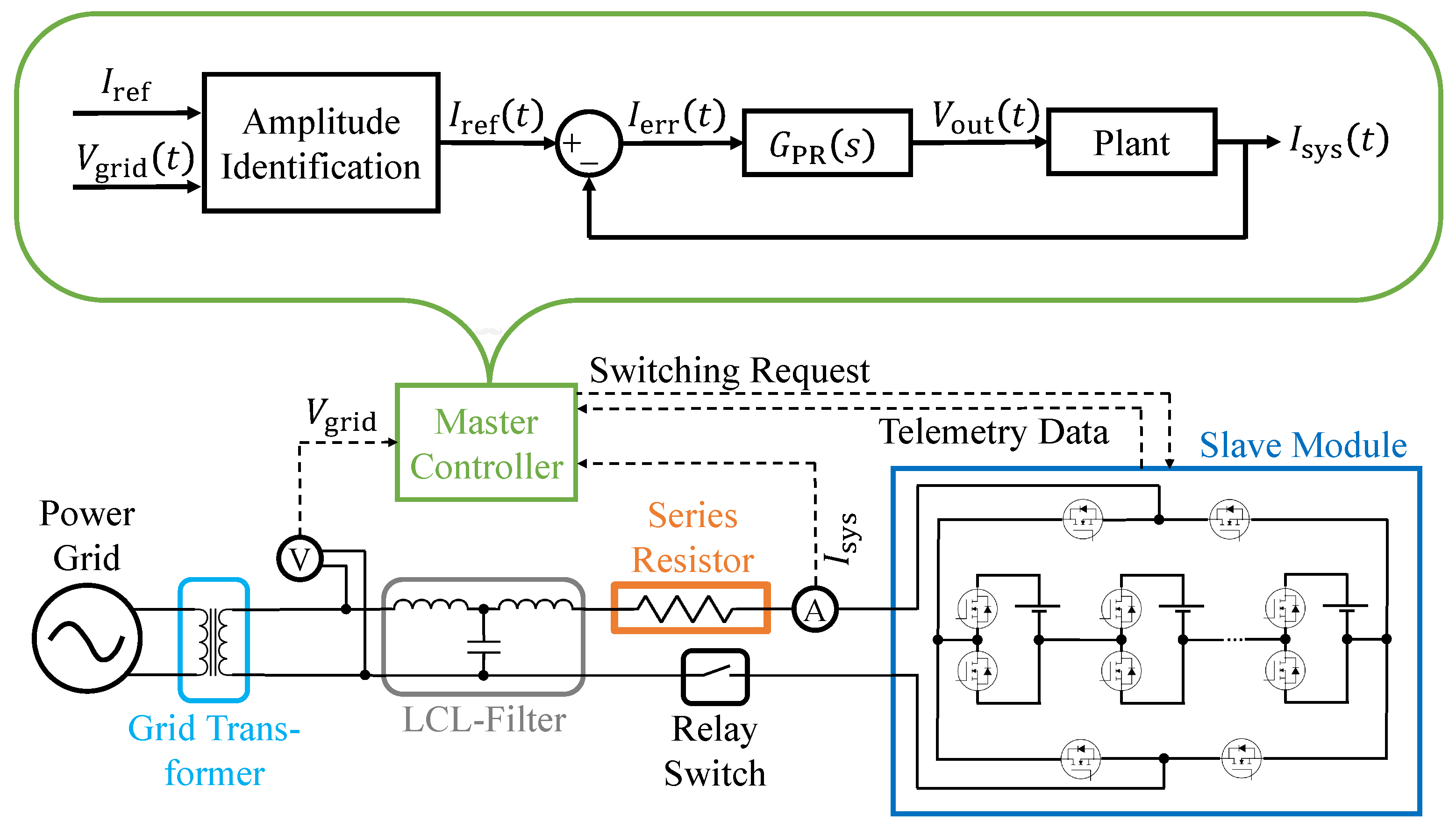
To ensure system safety before the actual hardware setup, a simulation was built using MATLAB/Simulink. The simulation structure is depicted in
Figure 2. The slave module, the actual RBS, is connected to the power grid via a grid transformer, an LCL-filter and a series resistor. The relay switch represents the disconnecting device between the slave module and the grid. Through system current and grid voltage measurements,
and
, respectively, the inputs for the PR controller subsystem were generated. These measurement values were manipulated with rounding and a time delay, to resemble the real sensors’ measurement deviations and update frequencies.
The controller plant model illustrates the master controller’s functionality. The scalar reference current and discrete-time measured grid voltage were used to identify the current amplitude at each time step. The resulting discrete-time reference current was compared to the measured system current and the discrete-time current error was fed into the controller. By using the PR controller’s transfer function, the output voltage response for the next time step was calculated.
The PR controller was initially designed with Simulink (control system toolbox) blocks for easier application, and later implemented with MATLAB code to better resemble the discrete-time workflow of the used microcontroller. However, mathematical functions, such as discrete-time integration and derivative, were still executed with Simulink blocks, since the simulation environment does not support direct function loops in MATLAB code. The PR controller runs within the master controller, where the exact switching characteristics are calculated and the individual switching request for each submodule is sent to the slave module.
The RBS consists of twelve modules based on a half-bridge MLI. It includes a single battery cell with a nominal voltage of and a nominal capacity of 20 . A standard Simulink battery block was used in order to model the battery cell. The metal-oxide semiconductor field effect transistors (MOSFETs) resemble state-of-the-art low voltage silicon MOSFETs with an internal conducting resistance of 1 . At the end terminals of the battery strand, a full bridge inverter was integrated, so positive and negative voltages could be applied. The LCL-filter uses two 470 inductors and a capacitor. The series resistor was varied from 10 to 250 . The grid transformer was set to an AC voltage with 32 RMS and a frequency of 50 . All elements within the simulation’s electric circuit were implemented from the Simscape electrical specialized power systems toolbox.
3.2. Measurement Setup
The measurement setup used the same structure as the simulation, so all controller values could be adopted from the simulation. It was built in two different configurations, a laboratory setup and a full power setup.
3.2.1. Laboratory Setup
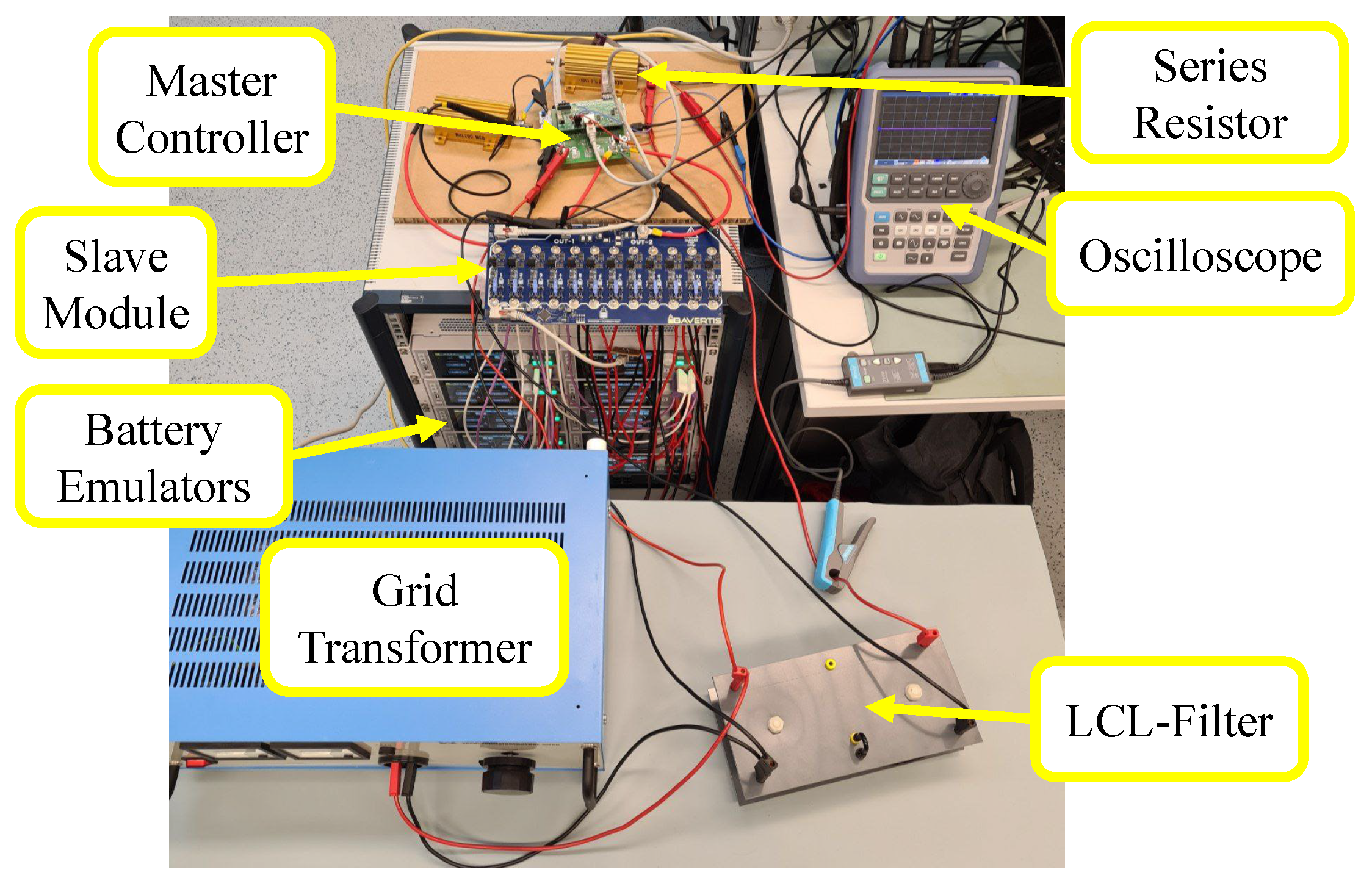
An overview of the hardware used for the laboratory setup is given in
Figure 3. As a grid transformer, a Thalheimer LTS 606 transformer was used, which can output a 50
AC voltage up to 230
RMS and a current up to 6
RMS. The LCL-filter was specially built for this setup, using toroidal inductor coils and a film capacitor with the values used for the simulation. A Rohde & Schwarz RTH1004 was used as an oscilloscope, while six Rohde & Schwarz NGM200 were used as battery emulators to increase the setup’s safety. Several different high-power resistors were used as series resistors, ranging from 20 Ω for maximum safety to 250 mΩ for minimum losses. The master controller and slave module were purpose-built for the charging system in cooperation with the BAVERTIS GmbH. The master controller was based on an STM32 microcontroller including the current and voltage measurements required to run the controller software. The slave module included the power MOSFETs for battery reconfiguration, single cell supervision and a balancing algorithm.
The PR controller code was translated from the MATLAB code and Simulink blocks into C-code. Therefore, the discrete-time integration and derivative blocks needed to be converted into program code. Monte Carlo integration was used to generate numeric integrations due to its simplicity and robustness for this specific task, since the expected results could easily be checked for plausibility. To keep the code simple with little computational intensity, the derivative tasks were implemented through the difference quotient of the previously smoothed noisy data. The PR controller was executed with an update frequency of 16 . As a result, an oversampling rate of 12.8 was achieved by the system with one slave module.
3.2.2. Full Power Setup
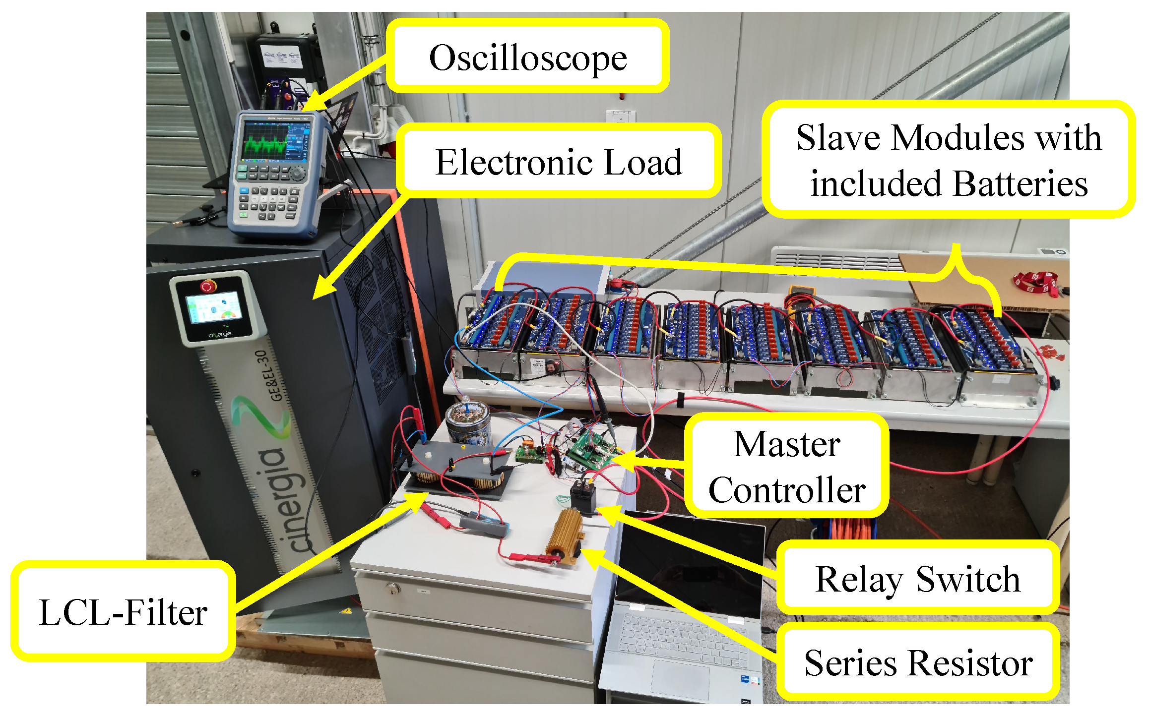
After ensuring safe and reliable operation below the threshold voltage of 48
RMS, the battery emulators were replaced with real batteries and up to eight slave modules were combined in a single battery system, as shown in
Figure 4.
The metric dimensions of the prismatic battery cells are 91 mm × 148 mm × 26.5 mm [
35]. The cells have a nickel-manganese-cobalt-oxide (NMC) cathode and a capacity of 20
. Since more than 6
RMS of charging current are needed to prove full power functionality, the grid transformer was replaced by a Cinergia GE & EL-30 AC electronic load. Due to the higher grid voltage and, thus, higher necessary safety precautions, an automotive relay switch was included into the system to establish or disconnect the connection between the RBS and the power grid. The relay switch was controlled by the master controller.
4. Results
This section describes the results obtained from the simulation and the hardware setup measurements.
4.1. Simulation Results
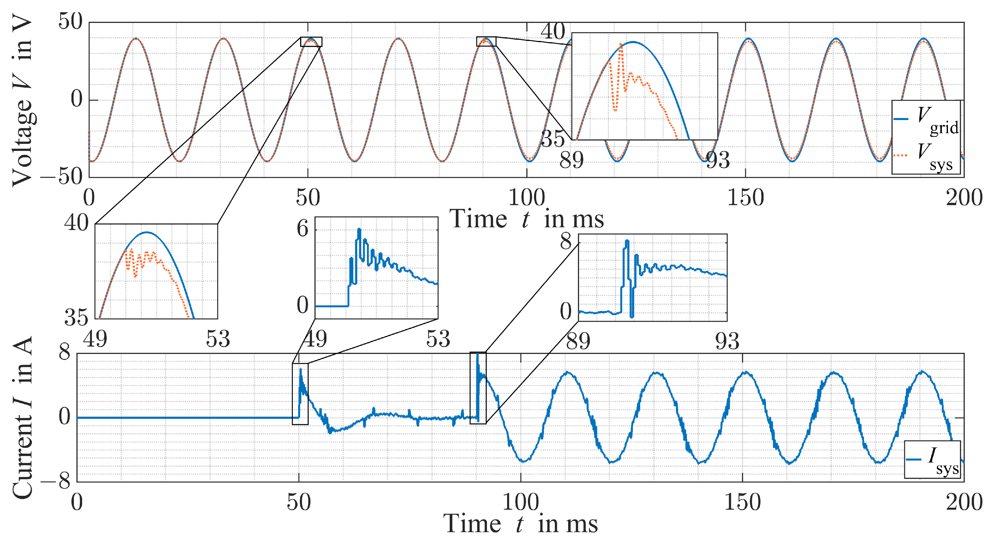
The simulation time was set to 200
to let the system fully stabilize. Initially, the power-up behaviour is neglected. Nevertheless, the system was able to fully settle in 40
, corresponding to two full wavelengths. The voltage and current behaviour are depicted in
Figure 5.
After an initial small current overshoot to 5
RMS, the desired current value was reached. This overshoot of 25% for the low settling time will not trigger an automatic circuit breaker with the trigger characteristics B, C, D (IEC 898) or types Z or K (IEC 947-2) as they are usually used in household electric installations. The current THD initiates at approximately 20% and drops to a constant of 6.8% after 40
, and two period durations. As can be seen in
Figure 5, the current ripples are caused by the controller’s 16
update frequency in combination with the relatively large voltage steps of 4
, approximately 10% of the peak voltage. Overall, a charging efficiency of 85.2% was achieved including battery and MOSFET conduction losses. A realistic usage scenario would include eight times the amount of battery modules for charging with the European power grid with 230 V RMS and a charging current of 13
RMS at a standard power outlet or up to 32
RMS at an AC charging station. Hence, it can be concluded that the current THD could be significantly improved with more modules, and the current overshoot does not trigger any standard circuit breaker.
A realistic system startup and connection sequence was simulated by disconnecting the battery system from the power grid. After the controller startup with a reference current of 0
RMS, the grid voltage curve is reached and the connection to the power grid can be established by closing the relay. As can be seen in
Figure 6, the connection is first established and after a transient oscillation the reference current is increased to the desired value.
The PR controller reaches the grid voltage instantly since it matches its output directly to the measurement value. After connection to the power grid at 50
, a current peak of 6
is measured, before reducing the system current to 0
within the next 30
. At 90
, the reference current was abruptly increased to 4
RMS.
Figure 6 shows that the correct current value is reached within 2
. The controller’s update frequency of 16
is reflected in the superimposed ripple of the current waveform.
4.2. Measurement Setup Results
For the measurements performed in the laboratory setup, the grid voltage was initially set to 17
RMS and two power resistors with 10 Ω each were included in series to the battery system. The basic functionality and communication between the master controller and slave module could therefore be validated in a safe testing environment. After this initial setup of the system, charging and discharging with less than 1
was performed. Afterwards, the system was expanded to two slave modules, and thus, a voltage range up to 68
RMS. The series resistors were replaced with four power resistors in parallel, each being rated at 1 Ω and combined having a resistance of 250 mΩ. With this setup, the measurements shown in
Figure 7 were recorded.
As can be seen, the grid voltage of up to ± 80
can be met by the multilevel battery system and a safe operation is ensured. In this case, a battery charging current of 4
RMS was controlled. The current THD was calculated to be 6.2% from the measurement data. Independently, the power grid’s voltage THD was 1.7% due to several non-linear high-power consumers within the same power grid subsystem in the laboratory building. Since the system’s topology did not permit parallel switching of the battery cells, the full system current acts on each individual cell switched into the current path. The measured cell was almost always switched into the current path in the measured time interval. This was caused by the state of charge (SoC) balancing algorithm. The batteries’ SoC is an important factor for battery ageing and lifetime. Therefore, the balancing algorithm tried to keep all batteries within a small SoC range. With this small variation, the cells’ SoCs stayed within a medium value, preventing excessive battery ageing of individual cells [
36,
37]. Despite a slight variation in the grid frequency, the synthesized output voltage of the inverter follows the frequency of the grid.
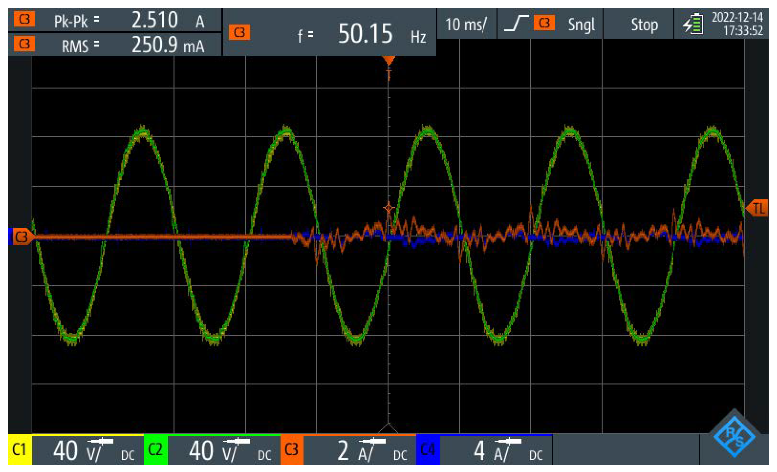
After the charging test with 56
RMS and 4
RMS, the startup procedure was tested using the values derived from to the simulation described previously. The oscilloscope measurements were triggered at a current value higher than 100
, resulting in the recording shown in
Figure 8.
At 35 into the measurement, the connection with the power grid was established. Both before and after the connection was established, the grid voltage was followed by the PR controller with no voltage spikes. The battery current was controlled to 250 RMS. The measured value approximated to the simulation results well. Since the charging power was low, the high current THD can be neglected.
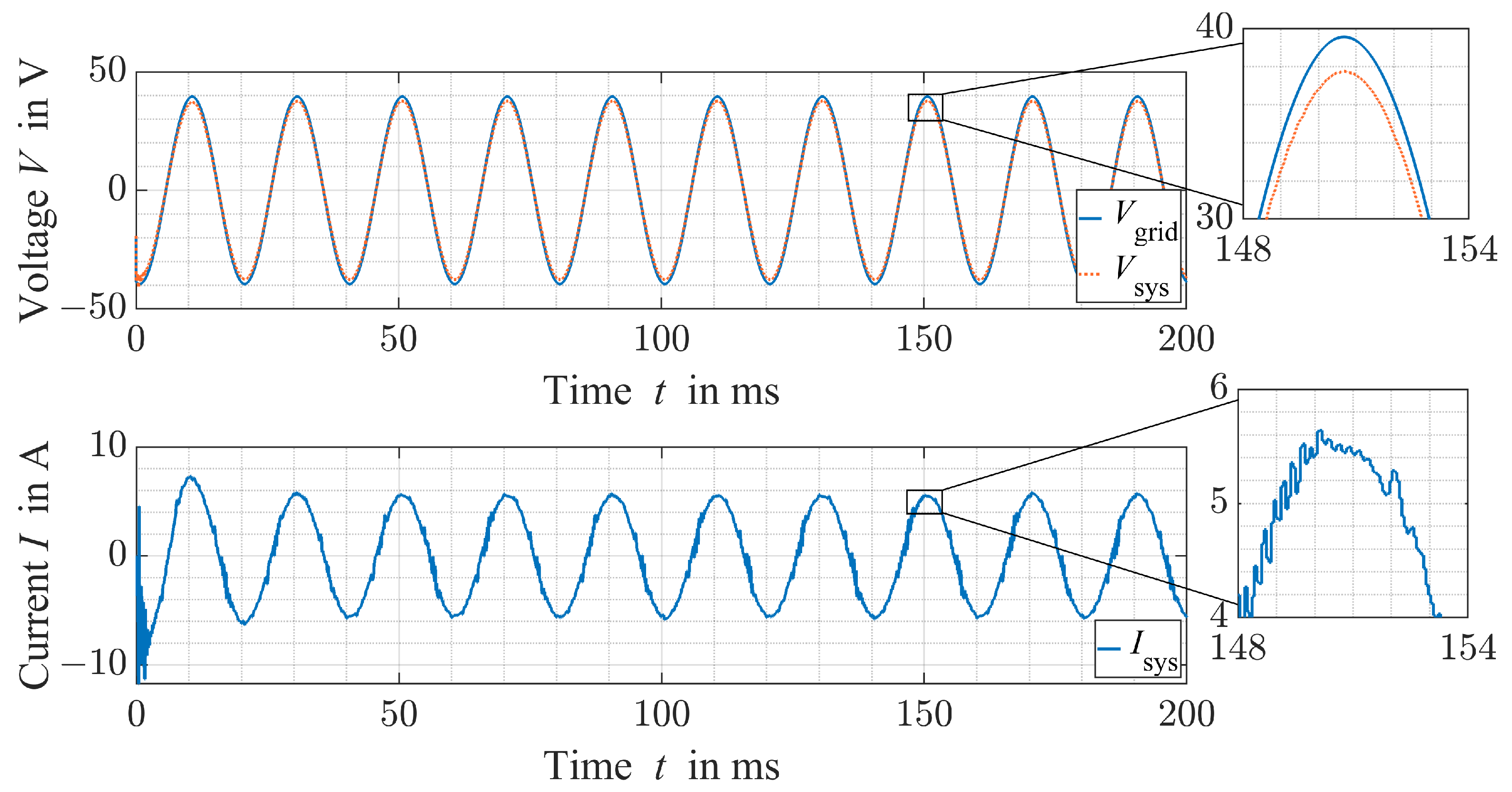
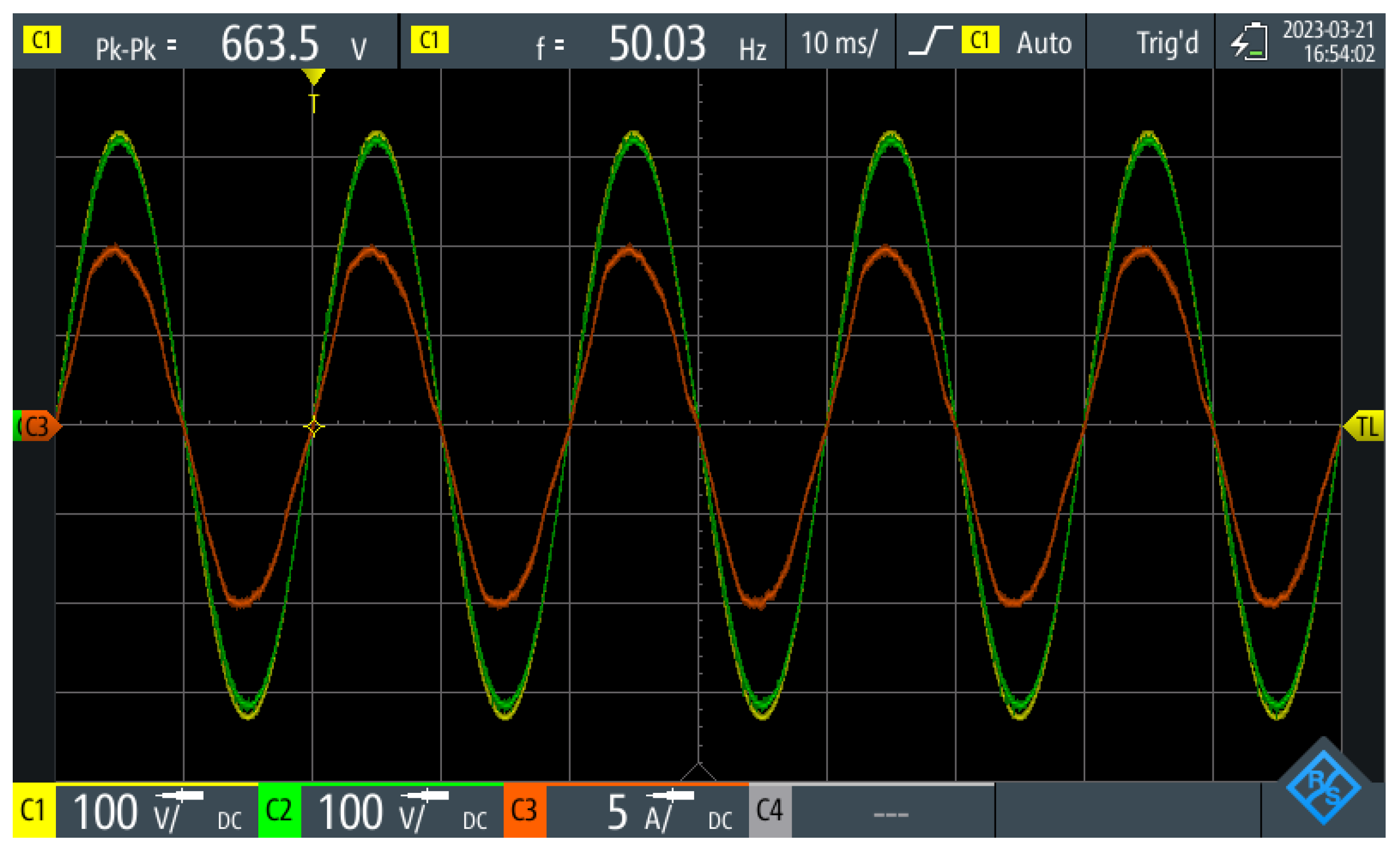
Eventually, the measurement setup was expanded to the full power setup. The full European grid voltage of 230
RMS was achieved and up to 7
RMS could be (dis-) charged. The system parameters with the maximum measured battery charging current are depicted in
Figure 9.
The measurements show a system charging power
of
. It can be seen that the system voltage was lower than the grid voltage. This results from the current flow in the battery charging direction. Analogously, a higher inverter voltage results in a discharging current of the battery pack depending on the resistance value of the applied resistor. The voltage delta between the grid and the system was relatively large due to the 1 Ω series resistor. Furthermore, a slight distortion of the current sine wave due to the inductors in the LCL-filter was observed. Nevertheless, a current THD of 4.5% was observed in this measurement. This value complies with the maximum of 5% specified by [
38]. A PF of 0.98 was calculated from the measurement data via MATLAB/Simulink without an additional PFC.
5. Discussion
The results obtained in this study expand the current state of scientific knowledge by measurements with a PR controlled MLI-based RBS in direct grid-tied operation. The outcomes prove that bidirectional charging is a key feature of RBS-based BEVs. Significantly more AC (dis-) charging power is available compared to conventional BEV OBCs. Thus, the findings are an important argument for vehicle manufacturers to develop BEVs with MLIs instead of conventional battery systems with dedicated power electronics for electric motor operation and charging.
Although the simulation and measurement results propose that bidirectional AC charging is intrinsically possible with an MLI-based RBS, several questions are yet to be answered. Firstly, the simulation was only performed with a single RBS module consisting of twelve submodules and a single full-bridge voltage inverter. Additionally, the system charging current was not raised over 4 RMS since the measurement setup was not designed for higher currents. A realistic usage scenario would include eight times the amount of battery modules for charging with the European power grid with 230 RMS and the charging current would usually be 16 or 32 RMS. The current THD was not low enough for grid usage in the simulation. However, it could be decreased with higher grid voltage and current.
The measurement results show that grid-tied charging and discharging is possible without special adjustments with an RBS by simply using an appropriate controller. The full European grid voltage, 230 RMS, and a system current of 7 were achieved, almost matching the AC charging and discharging speeds of current BEVs with V2G functionality. Given that the used battery pack has an energy capacity of only 7 , the achieved bidirectional system charging power of is still a reasonable demonstration of the new possibilities an RBS can provide for BEVs. Although the full power test setup did comply with the power grid’s maximum permitted current THD, the current distortion was still higher than expected. This was likely caused by the filter included in the test setup, but the definitive reason for this still needs to be investigated.
Since this study focused on the hardware setup and stationary measurements, battery balancing was only performed by periodically changing the switching priority of each submodule within the RBS modules. This leads to an imbalance in the SoC between the modules over a long period of time. Furthermore, charging was only performed with constant RMS current but not constant voltage to avoid battery overcharging. Additionally, battery temperature surveillance was not integrated into the test setup. These shortcomings will be addressed in future research and when implementing a charging setup in a BEV with an RBS.
Compared to [
34], the results in this paper suggest a higher current THD as well as a lower PF. While the previous work achieved a THD of approximately 0.7% at 7
, this setup resulted in a current THD of 4.5% at the same current rating. However, this can be partly explained by the PR controller’s lower update frequency of 16
compared to 20
in [
34]. Because [
31] only proposed the method, but didn’t carry out any experiments, a comparison between the results cannot be given. Ref. [
25] used a state-of-the-art bidirectional silicon carbide OBC and achieved a PF of 0.994, a current THD of 3.43% at
charging power and a peak efficiency of 95.3%. This is significantly more power, and thus an approximately four times higher current rating, explaining the lower THD. The efficiency cannot be compared within this paper, since no efficiency measurements were performed.
6. Conclusions and Future Outlook
In this paper, bidirectional charging with an MLI-based RBS was successfully implemented and tested in a simulation and actual hardware setup. For the initial test of functionality, the system was modelled with MATLAB/Simulink, before the hardware setup was implemented and tested. The simulation setup included twelve submodules within a single full bridge voltage inverter. Hence, bidirectional charging with a grid voltage of 32 RMS and a grid frequency of 50 was possible. Due to the large voltage steps in comparison to the peak voltage, the current THD was 6.5%. Furthermore, only a small current overshoot was observed in a direct startup scenario, such that a standard circuit breaker would not be trigger. During a more realistic startup scenario, where voltage parity was achieved before connecting to the power grid, fast synchronization and safe operation was observed. After successful simulation, the setup was built in hardware. Therefore, a setup with eight RBS modules, including a total of 96 submodules, was tested and investigated under realistic conditions. Similar to the simulation, a startup test was performed where grid synchronization was achieved before grid connection was established. From this safe operating point, the system current was manipulated in both directions, both charging and discharging the batteries from or to the power grid. At maximum, a bidirectional system charging power of up to with a grid voltage of 230 RMS and a system current of 7 RMS was achieved. A current THD of 4.5% was measured, meeting the grid conformity standards.
Future research needs to focus on implementation into a real BEV. For this purpose, several areas still need to be investigated. These mainly include communication with a vehicle charging device, such as a type 2 charging station via the proximity pilot and control pilot, and the galvanic isolation of the system to the grid. Although it is possible to operate a BEV with a Terre-Neutral power supply system, an Isolated-Terre system is generally used to increase system safety. The measurement setup in this case was operated as a Terre-Neutral system; therefore, the system was only isolated to the power grid through the grid transformer or the electronic load, not be included in an actual vehicle.
Author Contributions
Conceptualization, J.B., M.H. and M.K.; methodology, J.B.; software, M.H. and W.B.; validation, J.B., M.H. and W.G.; formal analysis, J.E., W.B., A.W. and M.K.; investigation, J.B., J.E., A.W. and M.K.; resources, W.G., A.L. and T.W.; data curation, J.B., A.W., A.L. and T.W.; writing—original draft preparation, J.B.; writing—review and editing, J.B., J.E., A.W., W.G., W.B., M.K., A.L. and T.W.; visualization, J.B., J.E. and M.H.; supervision, A.L. and T.W.; project administration, A.L. and T.W.; funding acquisition, M.K. and T.W. All authors have read and agreed to the published version of the manuscript.
Funding
This research is funded by the Munich Mobility Research Campus (MORE) and Electric Aircraft Propulsion (ELAPSED) as part of dtec.bw—Digitalization and Technology Research Center of the Bundeswehr which we gratefully acknowledge. dtec.bw is funded by the European Union—NextGenerationEU.
Institutional Review Board Statement
Not applicable.
Informed Consent Statement
Not applicable.
Data Availability Statement
Not applicable.
Conflicts of Interest
The authors declare no conflict of interest. The funders had no role in the design of the study; in the collection, analyses, or interpretation of data; in the writing of the manuscript; or in the decision to publish the results.
Abbreviations
The following abbreviations are used in this manuscript:
| AC | Alternating Current |
| BEV | Battery Electric Vehicle |
| BMS | Battery Management System |
| DAB | Dual-Active Bridge |
| DC | Direct Current |
| HV | High Voltage |
| MLI | Multilevel Inverter |
| MOSFET | Metal-Oxide Semiconductor Field Effect Transistor |
| NMC | Nickel-Manganese-Cobalt-Oxide |
| OBC | Onboard Charger |
| PF | Power Factor |
| PFC | Power Factor Correction |
| PLL | Phase-Locked Loop |
| PI | Proportional-Integral |
| PR | Proportional-Resonant |
| RBS | Reconfigurable Battery System |
| SoC | State of Charge |
| THD | Total Harmonic Distortion |
| V2G | Vehicle to Grid |
References
- Edenhofer, O. Climate Change 2014: Mitigation of Climate Change; Cambridge University Press: Cambridge, UK, 2015; Volume 3. [Google Scholar]
- Buberger, J.; Kersten, A.; Kuder, M.; Eckerle, R.; Weyh, T.; Thiringer, T. Total CO2-equivalent life-cycle emissions from commercially available passenger cars. Renew. Sustain. Energy Rev. 2022, 159, 112158. [Google Scholar] [CrossRef]
- Shi, X.; Pan, J.; Wang, H.; Cai, H. Battery electric vehicles: What is the minimum range required? Energy 2019, 166, 352–358. [Google Scholar] [CrossRef]
- Ru, Y.; Kleissl, J.; Martinez, S. Storage size determination for grid-connected photovoltaic systems. IEEE Trans. Sustain. Energy 2012, 4, 68–81. [Google Scholar] [CrossRef]
- Greene, D.L.; Liu, J.; Khattak, A.J.; Wali, B.; Hopson, J.L.; Goeltz, R. How does on-road fuel economy vary with vehicle cumulative mileage and daily use? Transp. Res. Part D Transp. Environ. 2017, 55, 142–161. [Google Scholar] [CrossRef]
- Khaligh, A.; D’Antonio, M. Global trends in high-power on-board chargers for electric vehicles. IEEE Trans. Veh. Technol. 2019, 68, 3306–3324. [Google Scholar] [CrossRef]
- Buberger, J.; Estaller, J.; Grupp, W.; Schwitzgebel, F.; Wiedenmann, A.; Mashayekh, A.; Kuder, M.; Eckerle, R.; Weyh, T. AC and DC Charging for Electric Vehicles with a Battery Modular Multilevel Management (BM3) Converter System. In Proceedings of the PCIM Europe 2022; International Exhibition and Conference for Power Electronics, Intelligent Motion, Renewable Energy and Energy Management, Nuremberg, Germany, 10–12 May 2022; pp. 1–8. [Google Scholar]
- Yuan, J.; Dorn-Gomba, L.; Callegaro, A.D.; Reimers, J.; Emadi, A. A review of bidirectional on-board chargers for electric vehicles. IEEE Access 2021, 9, 51501–51518. [Google Scholar] [CrossRef]
- Högerl, T.; Buberger, J.; Schwitzgebel, F.; Obkricher, L.; Estaller, J.; Hohenegger, M.; Kersten, A.; Kuder, M.; Eckerle, R.; Weyh, T. Battery Emulation for Battery Modular Multilevel Management (BM3) Converters and Reconfigurable Batteries with Series, Parallel and Bypass Function. In Proceedings of the 2021 IEEE International Conference on Environment and Electrical Engineering and 2021 IEEE Industrial and Commercial Power Systems Europe (EEEIC/I&CPS Europe), Bari, Italy, 7–10 September 2021; pp. 1–8. [Google Scholar]
- Lesnicar, A.; Marquardt, R. An innovative modular multilevel converter topology suitable for a wide power range. In Proceedings of the 2003 IEEE Bologna Power Tech Conference Proceedings, Bologna, Italy, 23–26 June 2003; Volume 3. [Google Scholar]
- Leite, R.S.; Afonso, J.L.; Monteiro, V. A novel multilevel bidirectional topology for on-board EV battery chargers in smart grids. Energies 2018, 11, 3453. [Google Scholar] [CrossRef]
- Chaudhary, S.K.; Cupertino, A.F.; Teodorescu, R.; Svensson, J.R. Benchmarking of modular multilevel converter topologies for ES-STATCOM realization. Energies 2020, 13, 3384. [Google Scholar] [CrossRef]
- Kuder, M.; Schneider, J.; Kersten, A.; Thiringer, T.; Eckerle, R.; Weyh, T. Battery modular multilevel management (bm3) converter applied at battery cell level for electric vehicles and energy storages. In Proceedings of the PCIM Europe Digital Days 2020; International Exhibition and Conference for Power Electronics, Intelligent Motion, Renewable Energy and Energy Management, Nuremberg, Germany, 7–8 July 2020; pp. 1–8. [Google Scholar]
- Jiang, J.; Bao, Y.; Wang, L.Y. Topology of a bidirectional converter for energy interaction between electric vehicles and the grid. Energies 2014, 7, 4858–4894. [Google Scholar] [CrossRef]
- Dini, P.; Saponara, S. Electro-thermal model-based design of bidirectional on-board chargers in hybrid and full electric vehicles. Electronics 2022, 11, 112. [Google Scholar] [CrossRef]
- Tashakor, N.; Farjah, E.; Ghanbari, T. A bidirectional battery charger with modular integrated charge equalization circuit. IEEE Trans. Power Electron. 2016, 32, 2133–2145. [Google Scholar] [CrossRef]
- Eull, M.; Zhou, L.; Jahnes, M.; Preindl, M. Bidirectional nonisolated fast charger integrated in the electric vehicle traction drivetrain. IEEE Trans. Transp. Electrif. 2021, 8, 180–195. [Google Scholar] [CrossRef]
- Theliander, O.; Kersten, A.; Kuder, M.; Han, W.; Grunditz, E.A.; Thiringer, T. Battery modeling and parameter extraction for drive cycle loss evaluation of a modular battery system for vehicles based on a cascaded H-bridge multilevel inverter. IEEE Trans. Ind. Appl. 2020, 56, 6968–6977. [Google Scholar] [CrossRef]
- Bughneda, A.; Salem, M.; Richelli, A.; Ishak, D.; Alatai, S. Review of multilevel inverters for PV energy system applications. Energies 2021, 14, 1585. [Google Scholar] [CrossRef]
- Vemuganti, H.P.; Sreenivasarao, D.; Ganjikunta, S.K.; Suryawanshi, H.M.; Abu-Rub, H. A survey on reduced switch count multilevel inverters. IEEE Open J. Ind. Electron. Soc. 2021, 2, 80–111. [Google Scholar] [CrossRef]
- Steinstraeter, M.; Buberger, J.; Minnerup, K.; Trifonov, D.; Horner, P.; Weiss, B.; Lienkamp, M. Controlling cabin heating to improve range and battery lifetime of electric vehicles. eTransportation 2022, 13, 100181. [Google Scholar] [CrossRef]
- Mashayekh, A.; Kersten, A.; Kuder, M.; Estaller, J.; Khorasani, M.; Buberger, J.; Eckerle, R.; Weyh, T. Proactive soc balancing strategy for battery modular multilevel management (bm3) converter systems and reconfigurable batteries. In Proceedings of the 2021 23rd European Conference on Power Electronics and Applications (EPE’21 ECCE Europe), Ghent, Belgium, 6–10 September 2021. [Google Scholar]
- Kersten, A.; Theliander, O.; Grunditz, E.A.; Thiringer, T.; Bongiorno, M. Battery loss and stress mitigation in a cascaded h-bridge multilevel inverter for vehicle traction applications by filter capacitors. IEEE Trans. Transp. Electrif. 2019, 5, 659–671. [Google Scholar] [CrossRef]
- Wong, N.; Kazerani, M. A review of bidirectional on-board charger topologies for plugin vehicles. In Proceedings of the 2012 25th IEEE Canadian Conference on Electrical and Computer Engineering (CCECE), Montreal, QC, Canada, 29 April–2 May 2012; pp. 1–6. [Google Scholar]
- Li, H.; Wang, S.; Zhang, Z.; Tang, J.; Ren, X.; Chen, Q. A SiC bidirectional LLC on-board charger. In Proceedings of the 2019 IEEE Applied Power Electronics Conference and Exposition (APEC), Anaheim, CA, USA, 17–21 March 2019; pp. 3353–3360. [Google Scholar]
- Dubarry, M.; Devie, A.; McKenzie, K. Durability and reliability of electric vehicle batteries under electric utility grid operations: Bidirectional charging impact analysis. J. Power Sources 2017, 358, 39–49. [Google Scholar] [CrossRef]
- Schwenk, K.; Meisenbacher, S.; Briegel, B.; Harr, T.; Hagenmeyer, V.; Mikut, R. Integrating battery aging in the optimization for bidirectional charging of electric vehicles. IEEE Trans. Smart Grid 2021, 12, 5135–5145. [Google Scholar] [CrossRef]
- Wassiliadis, N.; Steinsträter, M.; Schreiber, M.; Rosner, P.; Nicoletti, L.; Schmid, F.; Ank, M.; Teichert, O.; Wildfeuer, L.; Schneider, J.; et al. Quantifying the state of the art of electric powertrains in battery electric vehicles: Range, efficiency, and lifetime from component to system level of the Volkswagen ID.3. eTransportation 2022, 12, 100167. [Google Scholar] [CrossRef]
- Huang, X.; Meng, J.; Liu, W.; Ru, F.; Duan, C.; Xu, X.; Stroe, D.I.; Teodorescu, R. Lithium-Ion Battery Lifetime Extension With Positive Pulsed Current Charging. IEEE Trans. Ind. Electron. 2023, 1–8. [Google Scholar] [CrossRef]
- Teodorescu, R.; Blaabjerg, F.; Liserre, M.; Loh, P.C. Proportional-resonant controllers and filters for grid-connected voltage-source converters. IEE Proc.-Electr. Power Appl. 2006, 153, 750–762. [Google Scholar] [CrossRef]
- Helling, F.; Glück, J.; Singer, A.; Weyh, T.; Pfisterer, H.J. The AC Battery—A Novel Approach for Integrating Batteries into AC Systems. Int. J. Electr. Power Energy Syst. 2018, 104, 150–158. [Google Scholar] [CrossRef]
- Helling, F.; Kuder, M.; Singer, A.; Schmid, S.; Weyh, T. Low Voltage Power Supply in Modular Multilevel Converter based Split Battery Systems for Electrical Vehicles. In Proceedings of the 2018 20th European Conference on Power Electronics and Applications (EPE’18 ECCE Europe), Riga, Latvia, 17–21 September 2018; pp. P.1–P.10. [Google Scholar]
- Kersten, A.; Kuder, M.; Grunditz, E.; Geng, Z.; Wikner, E.; Thiringer, T.; Weyh, T.; Eckerle, R. Inverter and Battery Drive Cycle Efficiency Comparisons of CHB and MMSP Traction Inverters for Electric Vehicles. In Proceedings of the 2019 21st European Conference on Power Electronics and Applications (EPE ’19 ECCE Europe), Genova, Italy, 3–5 September 2019; pp. P.1–P.12. [Google Scholar] [CrossRef]
- Buberger, J.; Kersten, A.; Kuder, M.; Singer, A.; Mashayekh, A.; Estaller, J.; Thiringer, T.; Eckerle, R.; Weyh, T. Charging strategy for battery electric vehicles with a battery modular multilevel management (bm3) converter system using a pr controller. In Proceedings of the 2021 23rd European Conference on Power Electronics and Applications (EPE’21 ECCE Europe), Ghent, Belgium, 6–10 September 2021. [Google Scholar]
- Estaller, J.; Kersten, A.; Kuder, M.; Thiringer, T.; Eckerle, R.; Weyh, T. Overview of Battery Impedance Modeling Including Detailed State-of-the-Art Cylindrical 18650 Lithium-Ion Battery Cell Comparisons. Energies 2022, 15, 3822. [Google Scholar] [CrossRef]
- Abuagreb, M.; Beleed, H.; Johnson, B.K. Energy management of a battery combined with PV generation. In Proceedings of the 2019 North American Power Symposium (NAPS), Wichita, KS, USA, 13–15 October 2019; pp. 1–6. [Google Scholar]
- Sukumar, S.; Mokhlis, H.; Mekhilef, S.; Naidu, K.; Karimi, M. Mix-mode energy management strategy and battery sizing for economic operation of grid-tied microgrid. Energy 2017, 118, 1322–1333. [Google Scholar] [CrossRef]
- IEEE P519/D5.1; IEEE Draft Standard for Harmonic Control in Electric Power Systems. IEEE: Piscataway Township, NJ, USA, 2021; pp. 1–30.
| Disclaimer/Publisher’s Note: The statements, opinions and data contained in all publications are solely those of the individual author(s) and contributor(s) and not of MDPI and/or the editor(s). MDPI and/or the editor(s) disclaim responsibility for any injury to people or property resulting from any ideas, methods, instructions or products referred to in the content. |
© 2023 by the authors. Licensee MDPI, Basel, Switzerland. This article is an open access article distributed under the terms and conditions of the Creative Commons Attribution (CC BY) license (https://creativecommons.org/licenses/by/4.0/).

 ,
, 


