1. Introduction
Isolated microgrids are becoming more important as an alternative to conventional electric generators based on polluting diesel units. Isolated microgrids are based on renewables and storage and are created by power electronics-based equipment. They open a new paradigm on the operation and control of distribution networkss [
1,
2,
3]. In this direction, public events and faires can benefit from isolated microgrids. This fact allows for paving the way towards the participation of local renewable resources and electromobility assets. In [
4,
5,
6], different microgrid examples exist in the United States, Latin America, Europe and Japan.
Two types of converters may exist in a microgrid. The grid-forming converters act as a voltage source, so they fix the voltage and frequency level of the microgrid. They have to be capable of injecting or absorbing energy to maintain stability. The main objective of the grid-feeding converters is to inject power into the microgrid by acting as current sources. The amount of power injected depends on the voltage of the microgrid (fixed by the grid-forming converter) and the current injected by the grid-feeding converter.
The isolated microgrid voltage has to be generated by at least one grid-forming converter. Still, the microgrid can include several grid-feeding converters such as PV inverters, V2G chargers [
7] or stationary batteries [
8]. Accordingly, a critical point for the proper operation of the microgrid is the possibility to coordinate the grid-forming converter and the grid-feeding converters [
9,
10]. Most commercially available products use their communication protocols [
11,
12] and, sometimes, the user does not have access to use this protocol to develop new solutions. Although communications can assist safety [
13,
14], deploying a communication infrastructure cannot be viable in specific applications. In [
15], the authors propose a load-shedding strategy in a microgrid constant frequency operated microgrid to ensure the power balance.
The short circuits, overloads, and faults must be fully addressed in isolated microgrids. Isolated microgrids are deployed as a common supply system with different electrical connections, loads, generation entities, or storage systems. Each of these lines has to be protected according to power rating. Protective short-circuit devices are to be installed at the starting point of any line, and they have to provide adequate selectivity. Power electronics-based converters lack the short-circuit current capability of conventional rotating machines and usually cannot trigger standard protection devices such as circuit breakers. Therefore, different solutions must be adopted to protect these microgrids’ equipment and cabling and provide proper selectivity [
16]. On [
15,
17], the authors explore different outstanding issues applied to microgrid operation. Microgrids’ protection is essential [
18] and it should consider fault occurrence reaction [
19,
20,
21] and fault clearance [
22,
23].
This paper presents a live validation of the capabilities of power electronics and digital control to implement real microgrids and to demonstrate and show the concept in the Expoelectric, a fair related to renewables and electric mobility, in Barcelona (Spain), in Autumn 2018 and 2019 (
https://www.expoelectric.cat/ (accessed on 10 January 2023)). Different devices from different manufacturers are operated without any specific communication protocol.
This paper proposes the operation of the microgrid based on the VDE-AR-N-4105 [
24] standard as a tool to coordinate without any communications dedicated to all the assets in the microgrid. That assures the instantaneous power balance inside the microgrid while maximising the renewable production capability. The Master Inverter is responsible for the proper operations as a grid-forming converter. Further renewable energy and storage elements are connected to the microgrid by grid-feeding inverters.
Furthermore, the paper analyses the sizing and short-circuit protection System and implements novel features for grid-forming converters to correctly operate the microgrid in case of short-circuit with proper selectivity.
2. System Sizing and Overview
The main element of the microgrid is the Master Inverter. This inverter has been designed and constructed by CITCEA-UPC and teknoCEA. This inverter is the grid-forming inverter responsible for controlling and operating the microgrid. This Master Inverter creates a three-phase plus neutral system (standard in Europe), rated 400 V, 50 Hz with a TT distribution scheme using an isolation transformer. In a TT distribution scheme, the neutral and the exposed conductive parts are earthed. The converter’s typology is a bidirectional three-phase converter with the neutral connected to the mid-point of the DC bus. Thanks to such inverter typology, it can be as flexible as a low-voltage microgrid, where active and passive (uni)bidirectional devices can coexist and be connected arbitrarily to any phase. The Master Inverter is connected to an onboard (electric van) second-life battery pack that provides energy storage to supply the microgrid. The Master Inverter is sized 34.5 kVA, 50 A.
The goal of the Exploelectric18 was to feed the fair’s booths with an average power of 4.5 kW (1.5 kW/phase) for a whole day (from 10:00 a.m. to 06:00 p.m.). According to the power profile and other storage/generation devices connected to the microgrid, only a 30 kWh primary storage system was considered. The isolating transformer sets the power limit at the output of the Master Inverter, 15 kVA YNyn configuration. With this rating, the Master Inverter can provide sufficient current to trip the circuit breakers whenever there is a fault anywhere in the system. The short-circuit power results in three times the power required for the microgrid. The consumption and other grid feeders are galvanically isolated, providing a way to set the neutral scheme to TT.
The scope for Expoelectric19 is more ambitious, pretending to feed all booths except those of high power (more than 1.5 kW/booth). This is a maximum power of 30 kW (10 kW/phase). In this case, an average total consumption of 15 kW for a whole day is assumed. A capacity of 120 kWh should be required. However, as with Expoelectric18, this is without considering other energy resources. In the same way that the consumption loads to be fed are increased, the grid-feeding participation is also increased. It is considered to include up to 6 kW provided by electric vehicles plus additional photovoltaic participation, combining stable and intermittent energy resources. Thus, a 60 kWh central storage system is assumed. The Master inverter is limited by a 30 kVA YNyn transformer.
As has been introduced, the islanded microgrid (or Energy Ring) implemented in the live field test comprises several elements from different manufacturers. Thus, Expoelectric18 and Expoelectric19 adopt different grid-feeding assets and consumption levels.
Figure 1 and
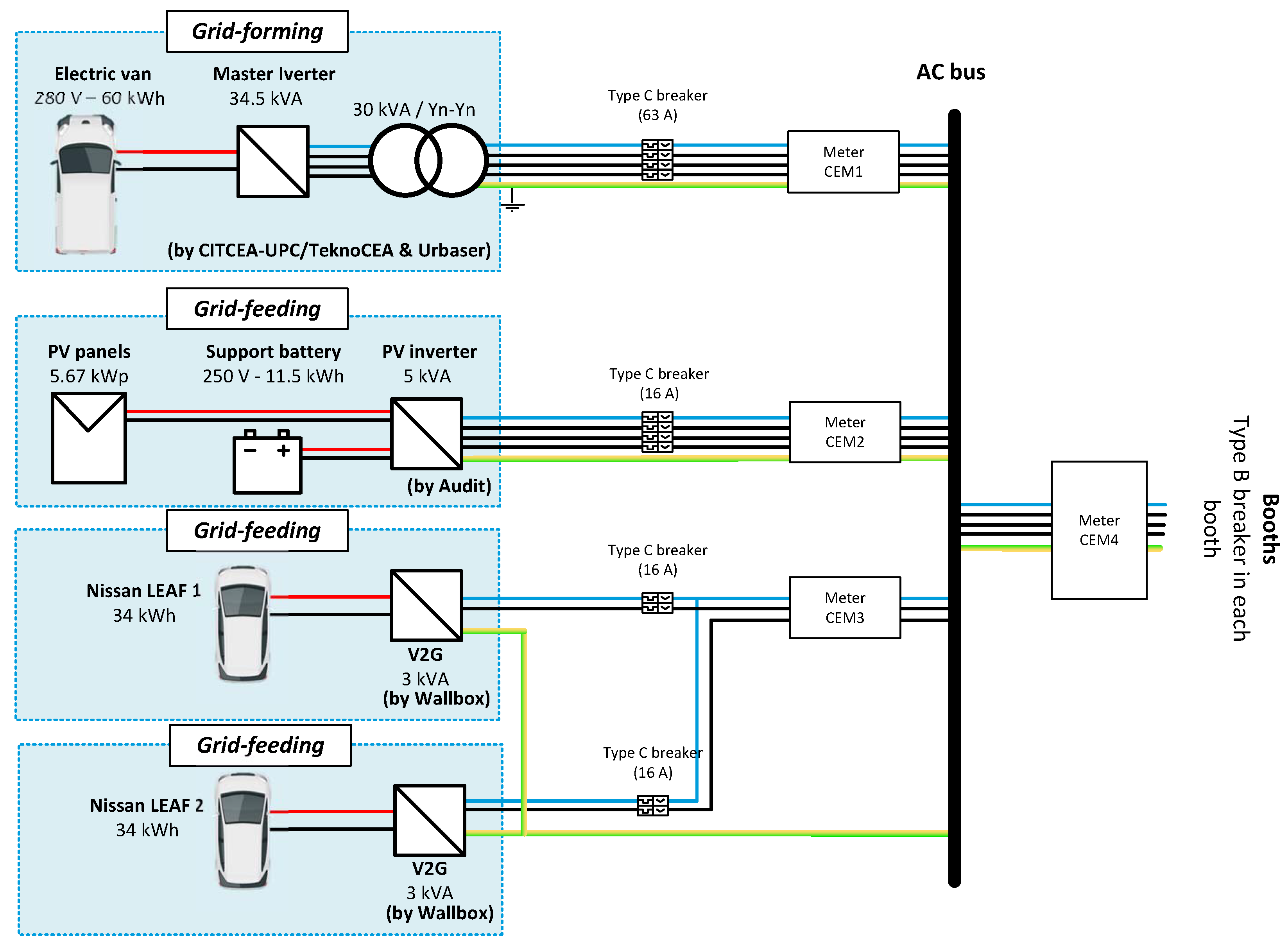
Figure 2 show the system overview for Expoelectric18 and Expoelectric19, respectively.
The main assets for each year’s experience are:
Expoelectric18 (
Figure 1). The main second-life battery used by the Master Inverter is of 30 kWh. The grid feeding devices are constituted by a PV carport (by Circutor) and a battery inverter connected to an EV battery (by FCC and SMA). The PV inverter is a single-phase equipment with a 48 V battery backup. PV panels are sized at 2 kWp. The battery inverter is a single-phase converter set to deliver up to 2 kWp. Finally, some loads (lighting, chargers, and power supplies, among others) are connected to the microgrid. The loads are planned to be up to 1.5 kW per phase.
Expoelectric19 (
Figure 2). The main second-life battery for the Master Inverter is of 60 kWh, doubling the capacity of the Expoelectric18 experience. Two V2G chargers constitute the grid feeding devices (by Wallbox) connected to two EVs and a PV installation with battery support (by Audit Energy). The V2G chargers are 3 kVA single-phase bidirectional inverters based on CHAdeMO. Each V2G charger is connected permanently to a 34 kWh Nissan LEAF. The PV installation includes eighteen 315 Wp high-efficiency panels (from JA Solar), a 5 kWp three-phase inverter (by Fronius) and an 11.5 kWh Lithium battery (from ByD). Finally, some loads (lighting, chargers, and power supplies, among others) are connected to the microgrid. The loads are planned to be up to 10 kW per phase.
3. Operation and Control
This section presents the most relevant considerations regarding the control, operation, coordination and fault response implemented in the Master Inverter. The demonstrated results are conducted at the laboratory level as the proof of concept to be applied in the field.
The microgrid operation can increase the voltage quality in low voltage systems, as mentioned in [
25]. The Master Inverter not only controls the voltage but also ensures the power quality of the overall network. In this sense, this converter manages the central energy reserve (primary storage) and maintains an acceptable voltage quality and supply. It also ensures enough security (short-circuit proof, protective curve adaptation to avoid overloads considering the limited short-circuit ratio of power electronics, among others). It also coordinates the other participants connected to the microgrid to manage the available resources.
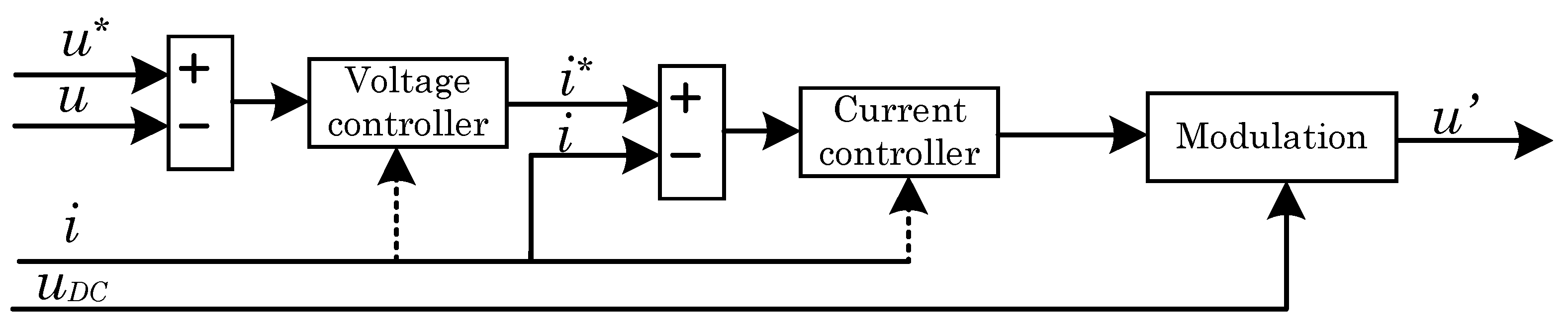
Figure 3 shows conceptually that the Master inverter implements two nested control loops for the mentioned purposes. The outer one corresponds to a voltage control loop, of which the control action acts as the setpoint for the inner current control loop. The Master Inverter is provided with an LC-type coupling filter at the AC side. Thus, the controlled voltage
u is the AC voltage at the AC-provided capacitors, and the controlled current
i is the current at the inductive coupling element. It should be noted that this
i current is considered for both current loop feedback and protective criteria, as is detailed in
Section 4.
3.1. Voltage Quality
The loads connected to the microgrid can be heavily unbalanced and non-linear. Therefore, the output voltage control of the Master Inverter has to be designed to keep the voltage power quality regardless of the loads connected. Furthermore, the power flow in this converter can be bidirectional, and during some instants, there can be generation going into the converter in some phases while supplying power to others.
The output voltage control of the Master Inverter is implemented, employing a stationary reference frame controller based on fractional proportional-resonant controllers (FPR) [
26]. The formulation of this controller is
where
and
correspond to the controller gains,
is a real value that provides an extra degree of freedom to the controller, and
is the tuning resonant frequency. The
value can be tuned to enhance the phase or gain at a set frequency, improving the tracking capacity of the controller. The dynamic response of the controller in the case of a sudden connection of a non-linear load can be observed in
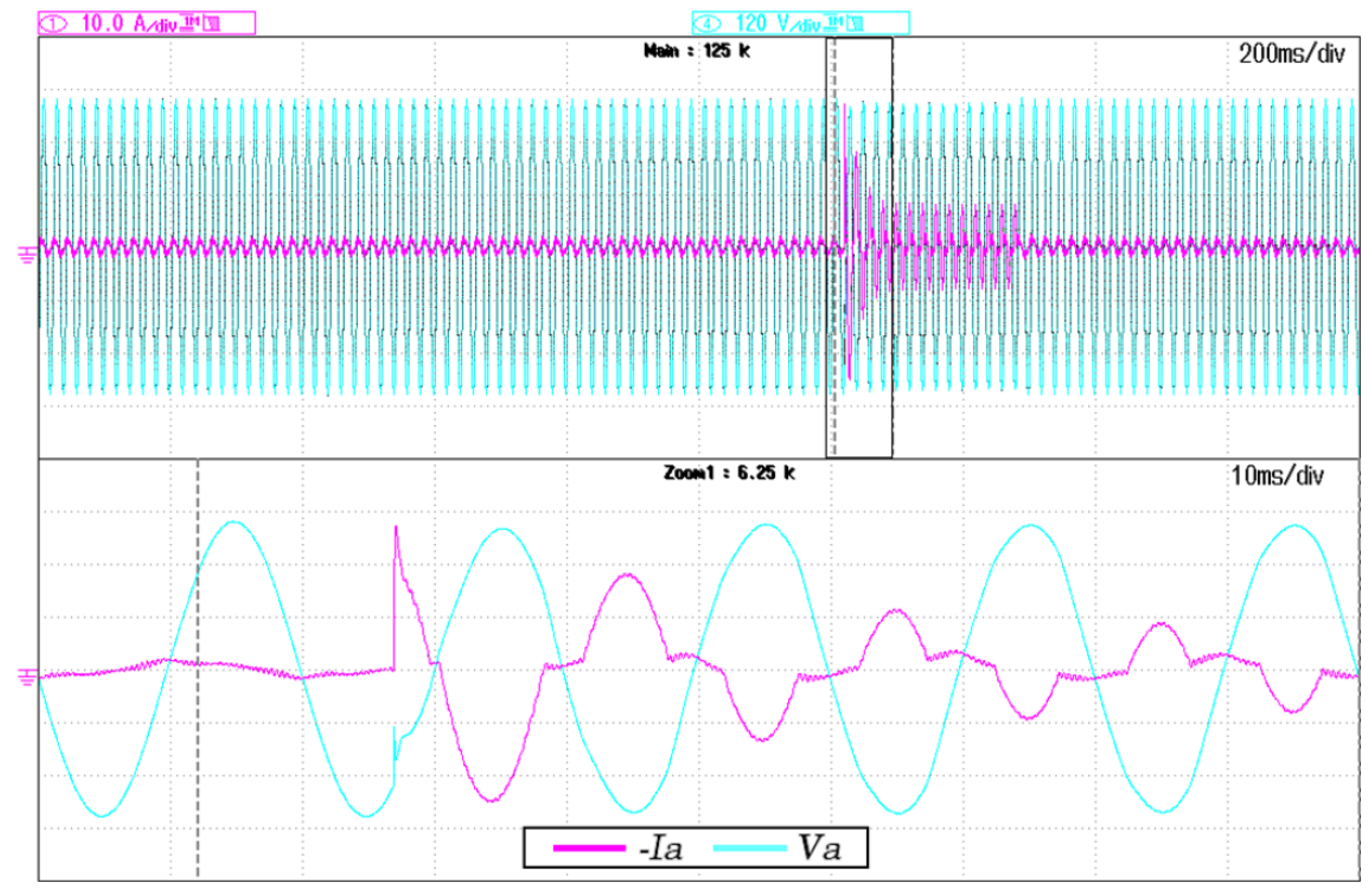
Figure 4. In the steady-state, the total harmonic distortion (THD) in voltage is lower than 2.5% for current THD levels up to 25%. This distortion level has been obtained from a Dranetz PX5 power analyser.
3.2. Coordination without Communications
The Master Inverter is responsible for operating the microgrid and maintaining the grid stability while assuring the loads’ supply. The main objective is to obtain the maximum possible energy from the distributed resources, such as the PV panels, while supplying the loads and charging the batteries for later use. This objective is achieved by adopting the standard VDE-AR-N-4105 [
24] and modifying the grid frequency as a function of the main battery State-of-Charge (SoC). Some examples of this standard’s application can be observed in [
27,
28,
29].
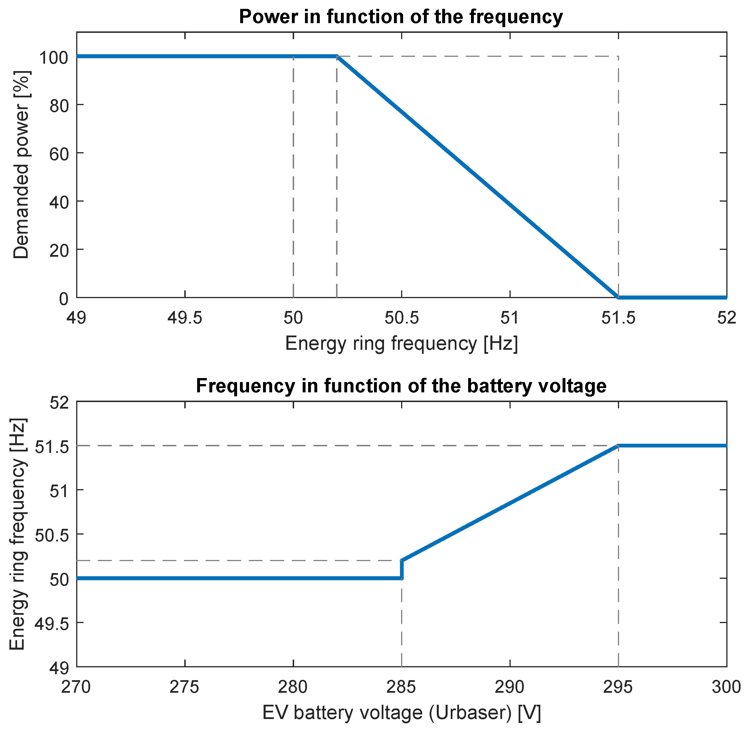
The power to be injected by the grid-feeding inverters is modified by the Master Inverter, as depicted in
Figure 5. Furthermore, the Master Inverter modifies the grid frequency according to the battery SoC, as depicted in
Figure 5. In this case, the SoC of the battery was unavailable, and the voltage was used as an SoC estimation.
If all the storage and generation elements cannot supply enough energy to the loads, the microgrid has to stop. For the proper installation, a bypass switch with the primary grid is provided to assure the continuity of the supply in the case of such an event.
3.3. The Primary Storage System Based on Second-Life Batteries
When using second-life batteries, it is relevant to know their state of health for proper microgrid sizing. For this purpose, both considered lithium-ion second-life batteries (30 kWh and 60 kWh) are tested at a 0.6C discharge rate. The considered valid operating range for this second-life battery is about 240–295 V.
Figure 6 shows how the voltage and energy exported evolves for the 30 kWh, and 60 kWh capacities are assumed. It should be noted that the case of 60 kWh is based on two parallel 30 kWh packs. After the testing process, the second-life batteries under study significantly affect time and actual capacity. When the 30 kWh battery is subjected to the 75 Adc discharge rate, the battery can export 24 kWh after 74 min. However, when the battery uses two 30 kWh packs at the same 75 A discharge rate, it achieves the minimum voltage after only exporting 42 kWh in 130 min. Each second-life battery pack’s possible different state of health can explain this.
4. Protection Considerations
Each installation line must achieve a specific overload capacity and short-circuit protection. Because the microgrid is a three-phase four-wire system, different short-circuit types with different fault currents and over-loads must be considered. Due to the current limit of the Master Inverter, different strategies are used to protect the installation in case of an over-current or a short circuit.
4.1. Short-Circuit Proof Control Scheme
As mentioned, different types of short circuits can occur in a microgrid. The provided short-circuit current has to be provided by the Master Inverter. The Master Inverter has to handle the short-circuit fault event and the fault recovery. Both fault entry and recovery must be as fast as possible and smooth to avoid other electric issues. The Master Inverter includes a short-circuit proof algorithm that digitally controls both the short-circuit current magnitude and the current waveform to be sinusoidal at the fundamental frequency.
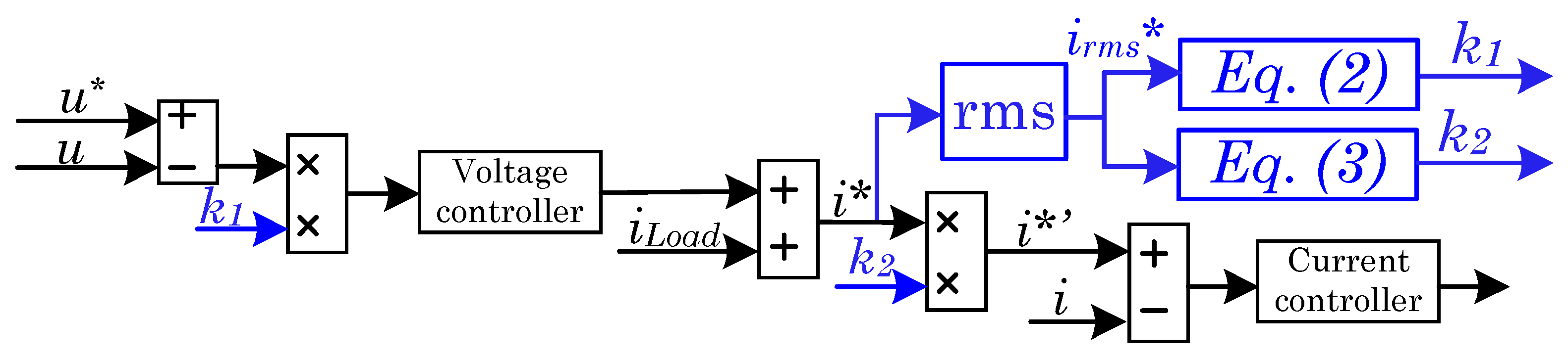
Figure 7 shows the concept of the short-circuit control scheme. This control scheme is addressed by considering two nested control levels; AC side voltage control (
u) and an inner Master Inverter output’s current control (
i).
In
Figure 7 can be observed how the voltage and current references of the Master Inverter are modified to be adapted for any over-load situation (short-circuit in the extreme case). Both voltage and current references are indicated in
Figure 7 using the superscript (
). The blue parts are added for the short-circuit proof enhancement concerning a conventional voltage-current nested control loop. The algorithm is based on computing the per phase root mean square (RMS) value of the current reference at the AC side,
to obtain
[
19]. From this RMS value, two other factors are calculated;
and
. The first factor,
, allows regulating the voltage reference dynamically. Thus, this
factor aims to attenuate the microgrid voltage under short-circuit or high overload situations. The
factor is computed as
where
is the maximum desired Master Inverter output’s RMS current. The parameter
K in
calculation allows us to adapt the system response speed to address the overload or short-circuit occurrence.
K can range between 0 and 1. The second factor
limits the final current reference (
) to the rated value when the fault situation appears following
For the fault clearance, it is necessary to act cautiously in the case of the factor . Note that the factor is the one that handles the voltage reference. In this sense, the sign is used. When the sign is positive, the fault is potentially in the recovery transient. For this reason, the factor is filtered to ensure a smooth voltage recovery under this last assumption. This filter should provide a smooth time constant to be a trade-off between time recovery and possible overshoots. It is recommended to be about four to six fundamental periods.
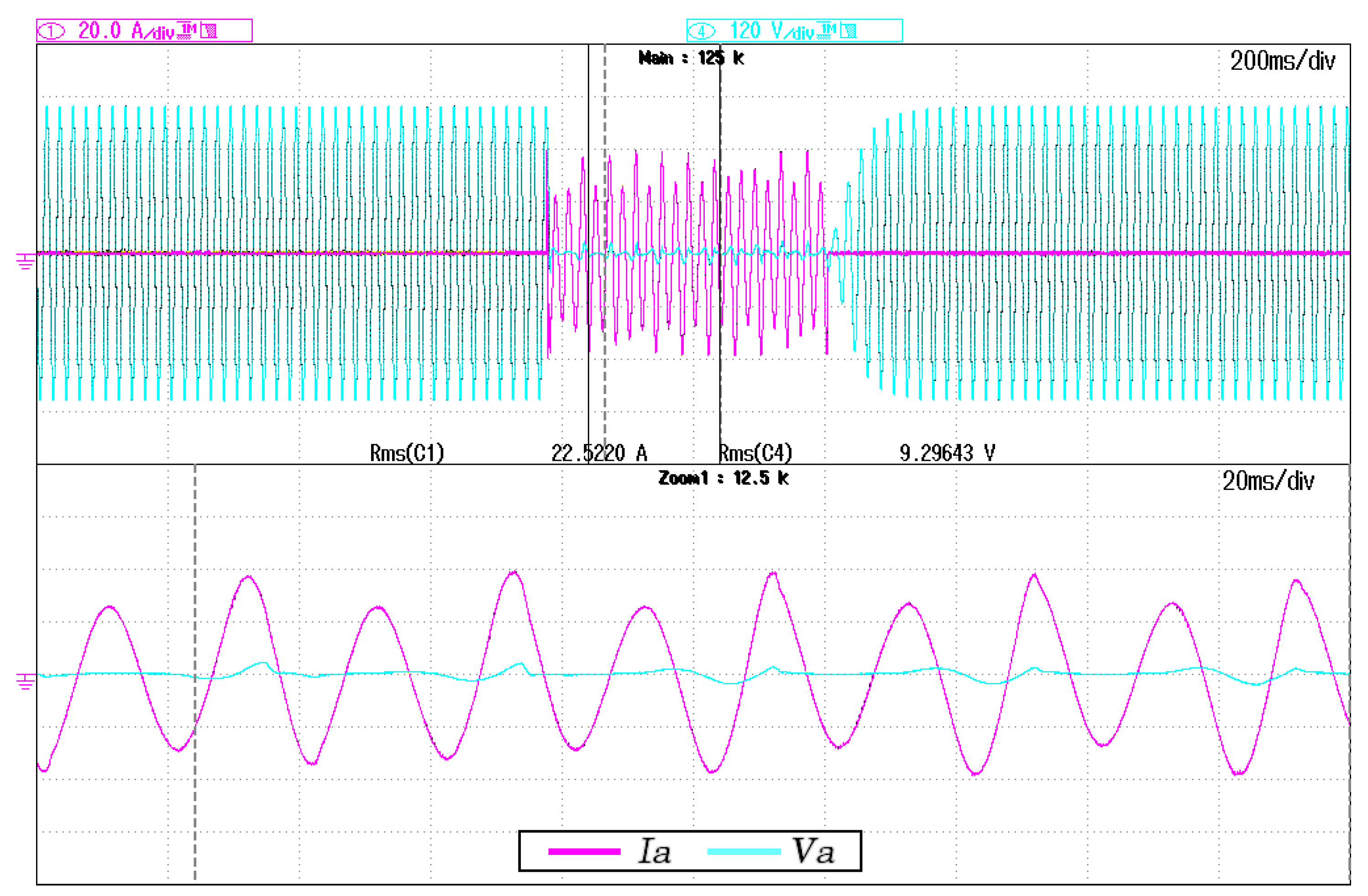
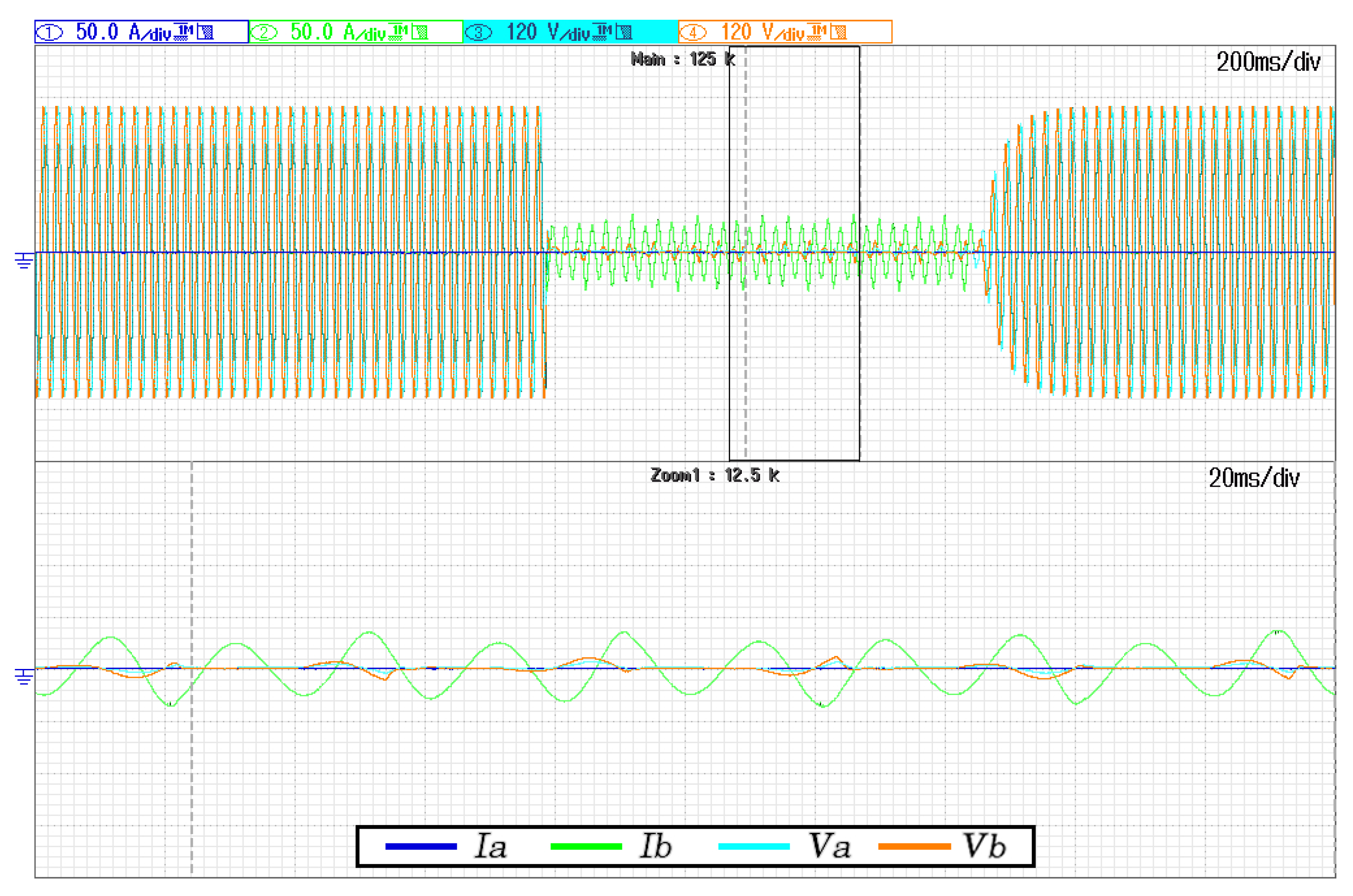
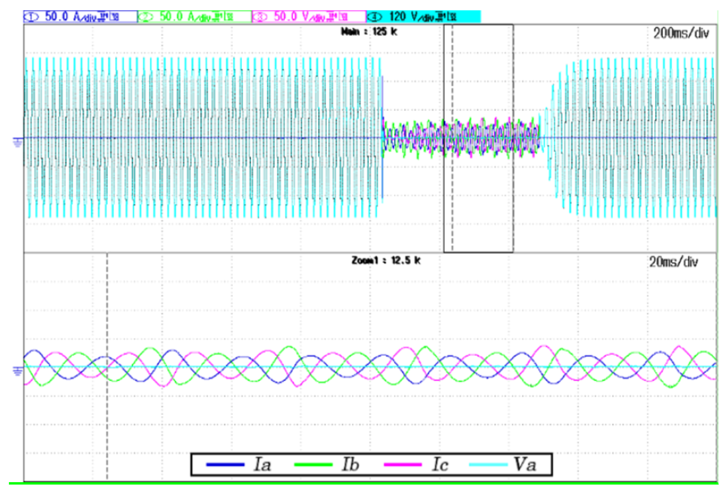
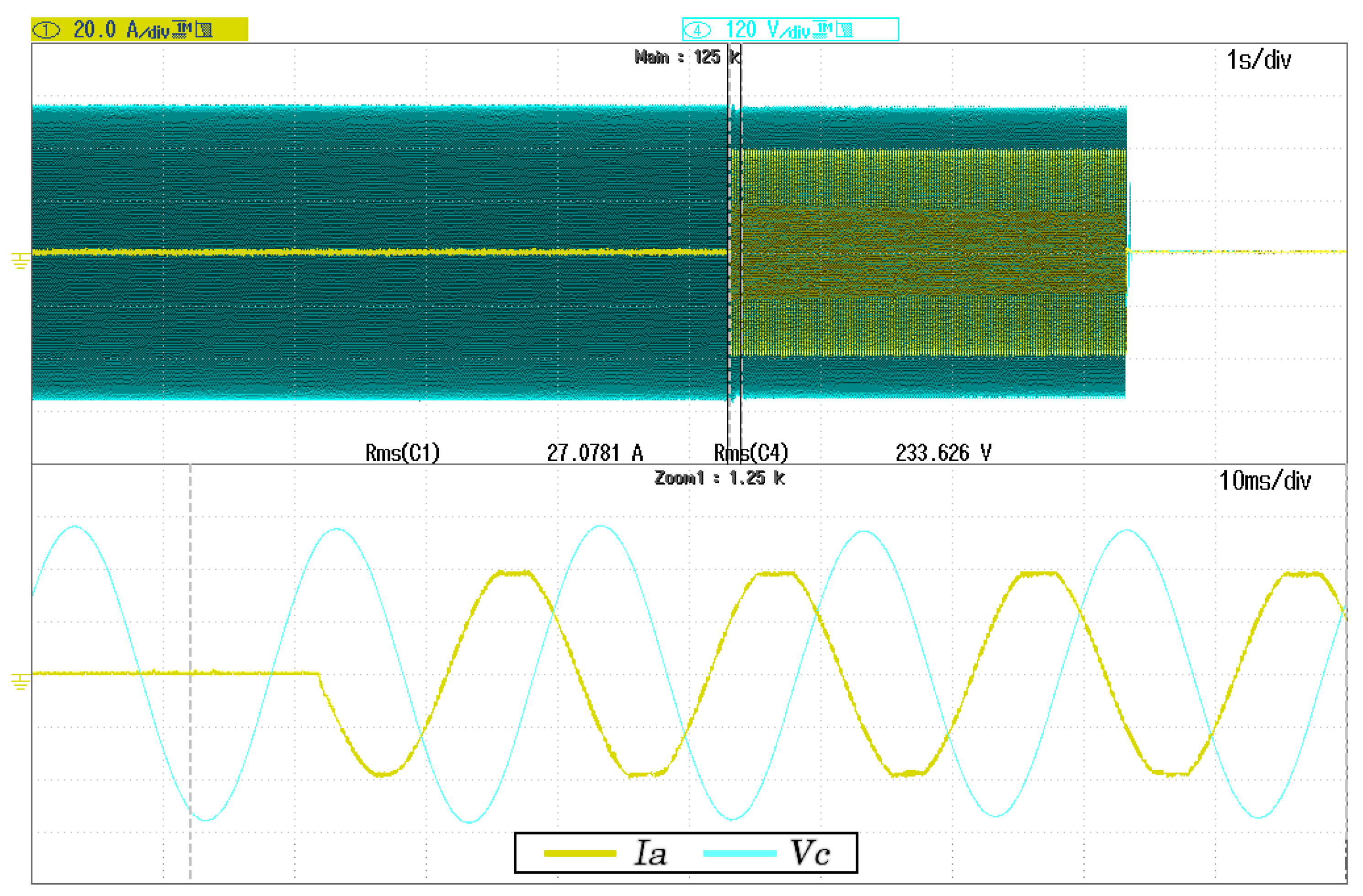
Figure 8,
Figure 9 and
Figure 10 shows the voltage and current waveform involved in the case of a single-phase short-circuit, two-phase short-circuit, and three-phase short-circuit testing, respectively. The Master Inverter’s phase to neutral voltage and output line currents are indicated as
and
, where the subscript
x represents each
a,
b or
c lines of the low voltage microgrid. The short-circuit proof algorithm parameters for all these testing captures are
K equal to 0.9 and
equal to 22 A
. Thus, in
Figure 8,
Figure 9 and
Figure 10 can be validated that the short-circuit poof algorithm reduces the voltage rapidly when the fault occurrence. Moreover, the algorithm allows for recovering the voltage progressively in all situations under the fault clearance situation. Furthermore, the current is maintained almost pure sinusoidal with a low-frequency oscillation. This low-frequency oscillation is an effect of the
K factor selected, so the
is affected by it. The higher the
K factor is, the more the voltage speed reduction results, but the higher the current oscillation rises.
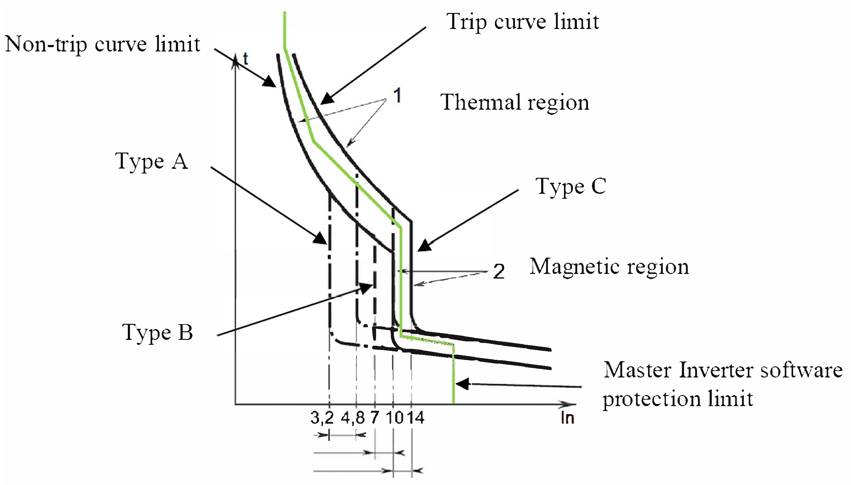
4.2. Ideal Virtual Circuit Breaker Trip Curve
To assure selectivity in the installation, a three-phase four-pole type C circuit breaker is placed at the output of the Master Inverter. Each line is protected by a single-phase Type B circuit breaker at the consumption side. Note that an upstream type B breaker is discarded due to the difficulty of finding such devices of high current but mainly because time-current reconfiguration could be necessary for microgrids.
The Master Inverter is power electronic-based. Implying a limited short-circuit power and a waveform of the overload current that may differ from the one provided when the mains participate. Thus, it is not secure enough to trust only the trip curves provided by physical circuit breakers. An extra virtual circuit breaker tripping curve is implemented in the Master Inverter, as shown in
Figure 11.
The extra virtual circuit breaker monitors each phase, adding redundancy and resilience to the protective system. In that sense, the Main Inverter can stop feeding the fault even if the corresponding physical circuit breaker does not respond as expected. Thus, it is considered to implement the virtual circuit breaker trip curve as the ideal trip curve of a type B main circuit breaker. The virtual circuit breaker trip response has been tested according to the following assumptions:
Short-circuit proof algorithm set with
at 30 A, see Equation (
2).
Ideal trip curve set as a 6 A type B circuit breaker, as protection panels in the fair, are constructed. The ideal trip curve pair current-time is represented by
Table 1. Between the current-time defined points, a linear interpolation is assumed.
Testing load is 6.2 kW rated power per phase (about 27 A).
Upstream (Master inverter side) 16 A type C physical circuit breaker installed.
Downstream (load side) 10 A type C physical circuit breaker installed.
With the previous considerations, any physical breaker should trip in less than a few minutes. However, the virtual breaker should stop after about 3 s.
Figure 12 shows the correct behaviour of such virtual breaker implementation where the Master Inverter stops the output power within 3 s.
5. Results and Discussion
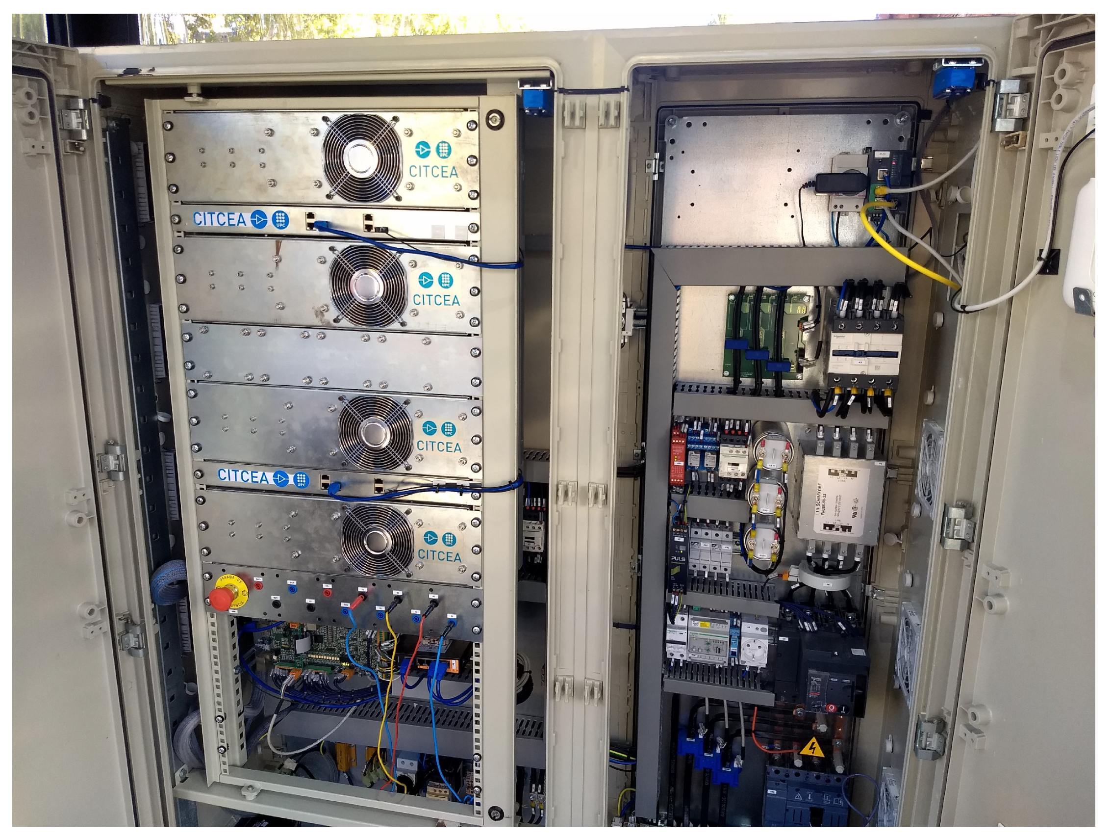
This section presents different results from the live field experience of creating an isolated microgrid in the Expoelectric18 and Expoelectric19 fairs. To illustrate the relevance of these experiences and contextualise their extension,
Figure 13 shows the Master Inverter and the main storage system at Expoelectric18. Moreover, for the Expoelectric18 experience,
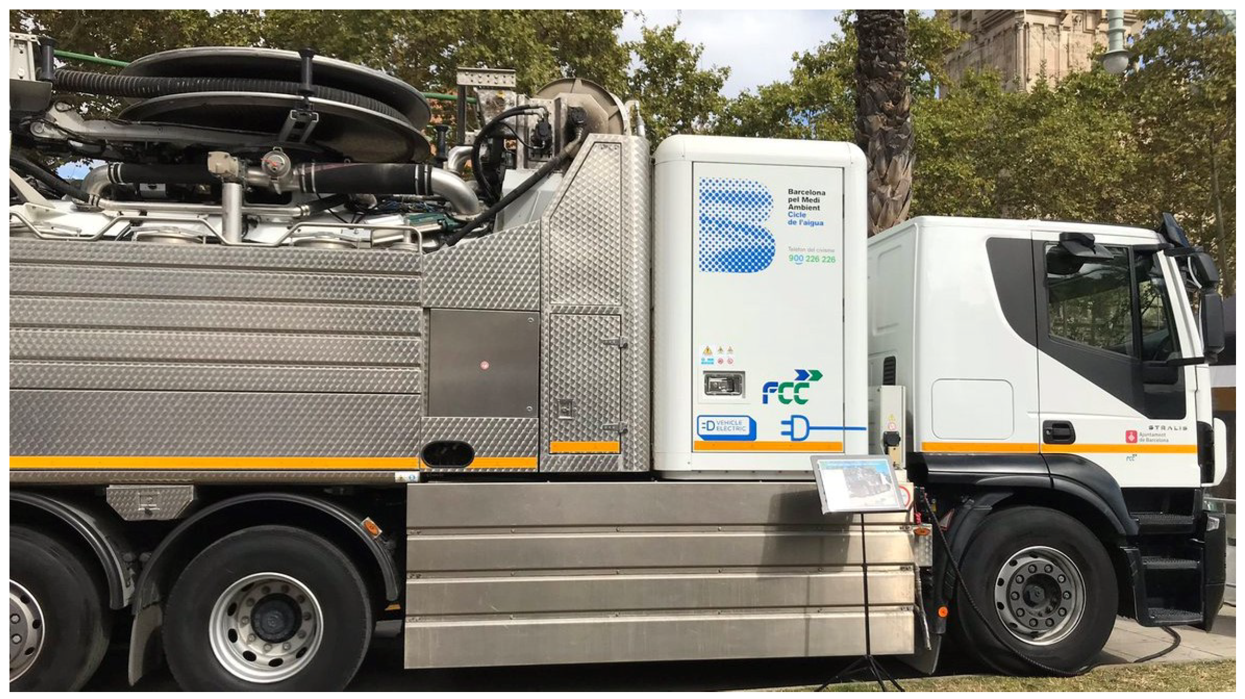
Figure 14 and
Figure 15 show the grid-feeders’ participants.
Figure 14 shows the electric truck that provided about 2 kWp to the microgrid. The inverter used to interconnect the truck with the microgrid can be observed in
Figure 16 as the yellow inverter behind the Master Inverter.
Figure 15 shows the PV carport installed for Expoelectric18. Furthermore,
Figure 17 and
Figure 18 show the grid-feeders used during Expoelectric19.
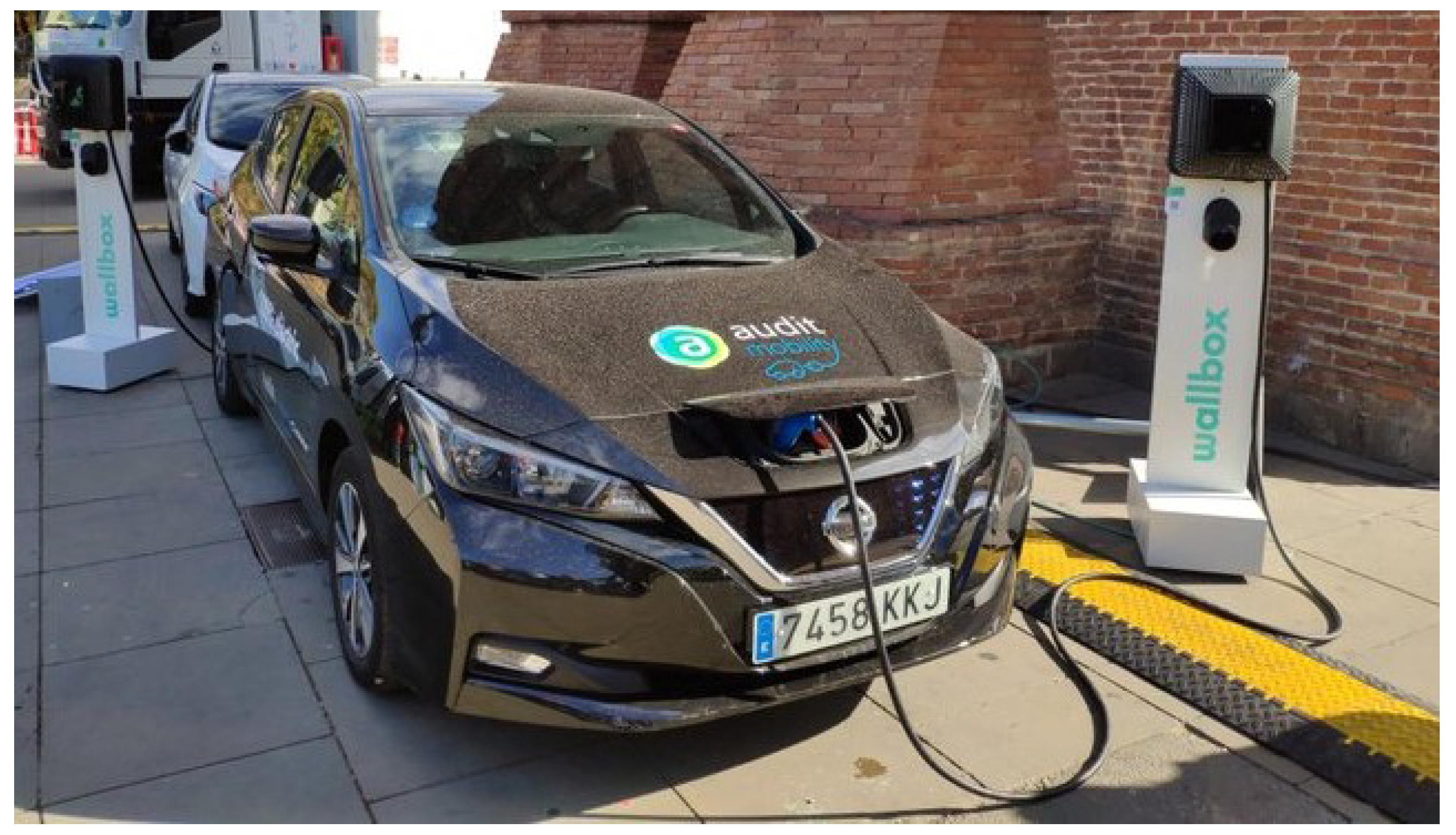
Figure 17 shows the V2G chargers, and
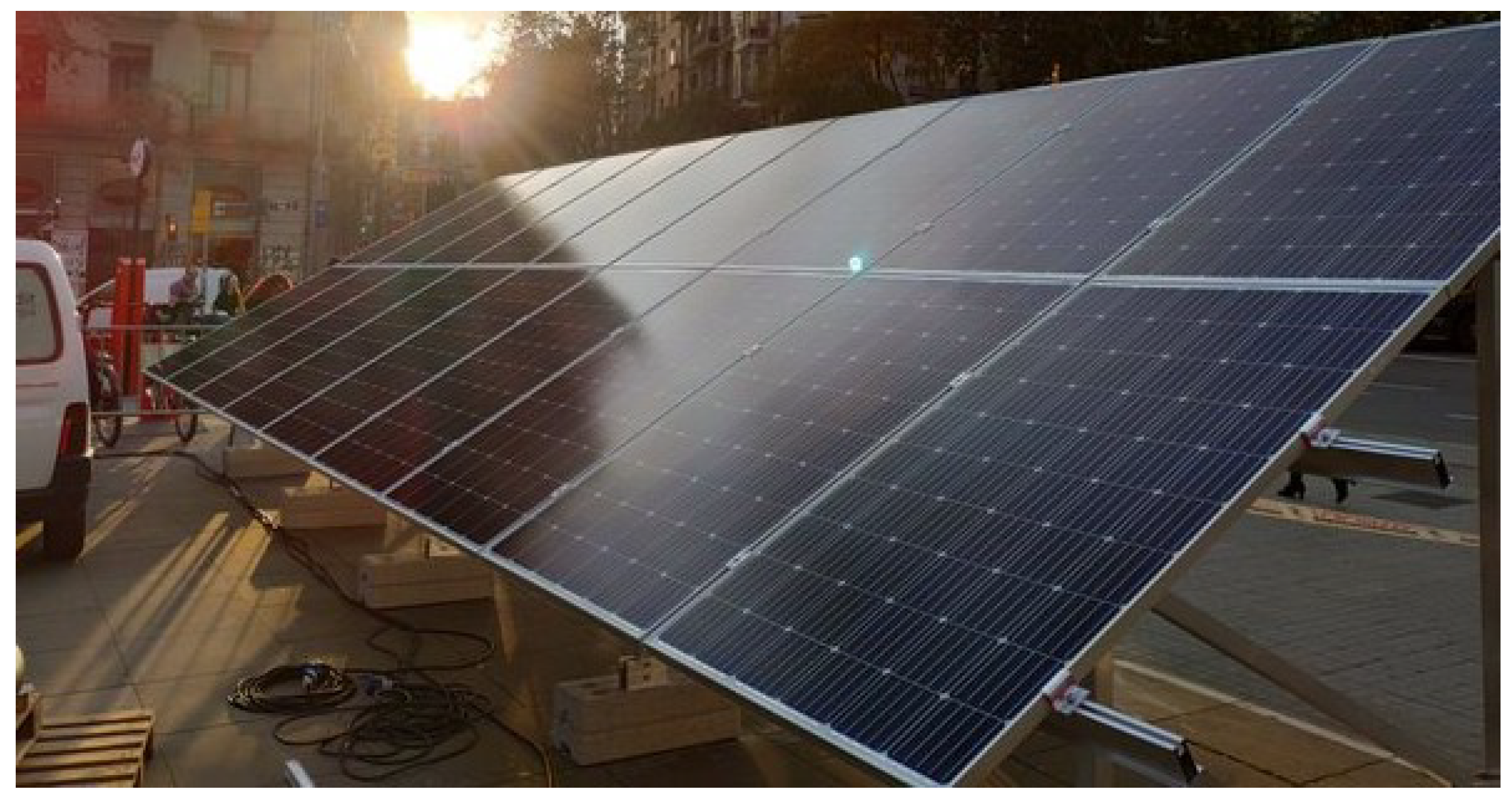
Figure 18 the PV installation. Finally,
Figure 19 shows a picture of the booths.
5.1. Expoelectric18 Results
The Expoelectric18 fair will be held in Barcelona on 6 and 7th October 2018 (from 10:00 a.m to 18:30 p.m, approximately). For the system overview, refer to
Section 2—
Figure 1. In phase
a, it is connected to the EV inverter; the
b phase only considers consumption and the PV system is connected to phase
c.
Expoelectric18 offered two cases corresponding to different daily climatology and consumption profiles. All results in this section have been obtained by monitoring the Master Inverter’s output connection. All data presented for this year has been gathered using a Dranetz PX5 power analyser. The data has been minimally processed for better understanding.
5.1.1. Saturday, 6 October 2018
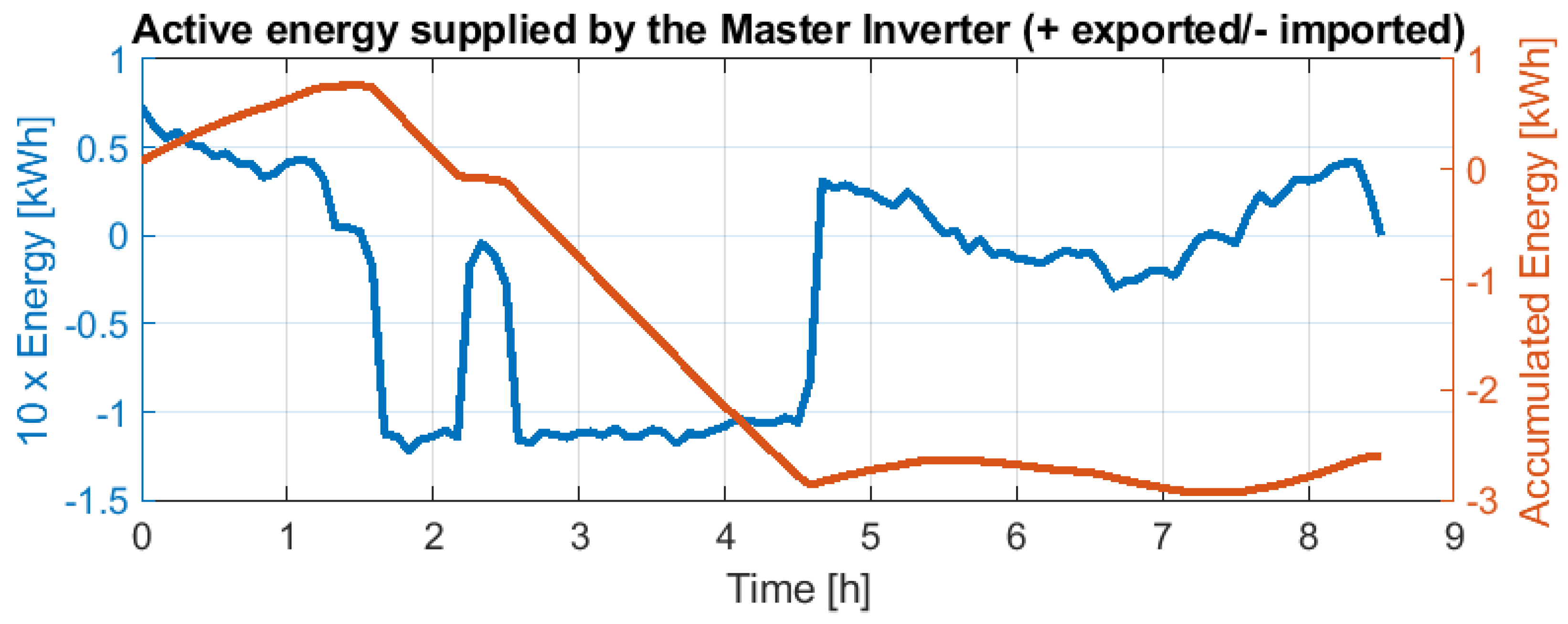
The scheduled loads were maximum of 1.5 kW/phase.
Figure 20 shows the Master Inverter’s exchanged energy and total accumulated energy (by integrating exchanged energy). Positive means exported energy (dispatched to the microgrid), while negative corresponds to imported energy (coming from the microgrid thanks to the other active sources). The energy regulation responds to the adaption of VDE-AR-N-4105 [
24] through the specification previously detailed in
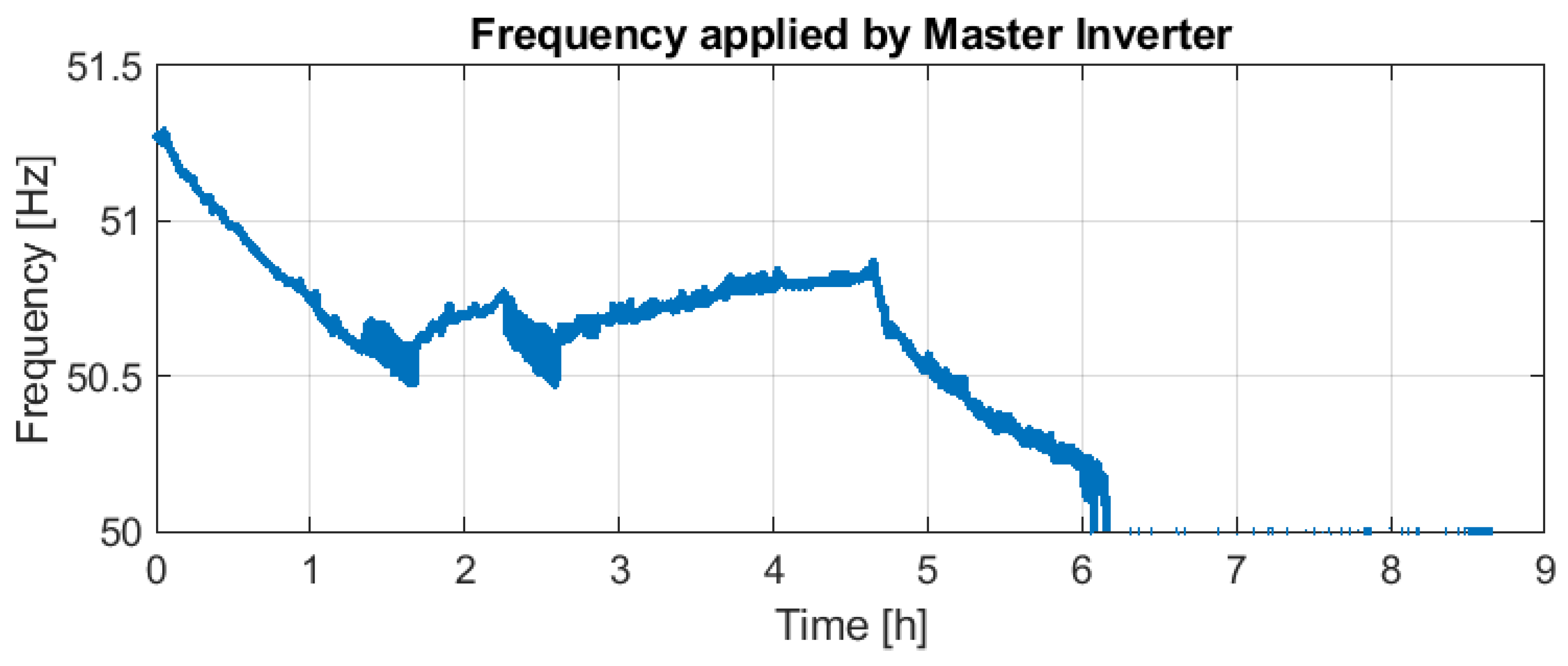
Figure 5. This yields the frequency response imposed by the Master Inverter shown in
Figure 21. Due to the only metering point, the Master Inverter losses are not considered in the analysis. Thus, even importing energy at the end of the day, as shown in
Figure 20, the frequency remains at 50 Hz.
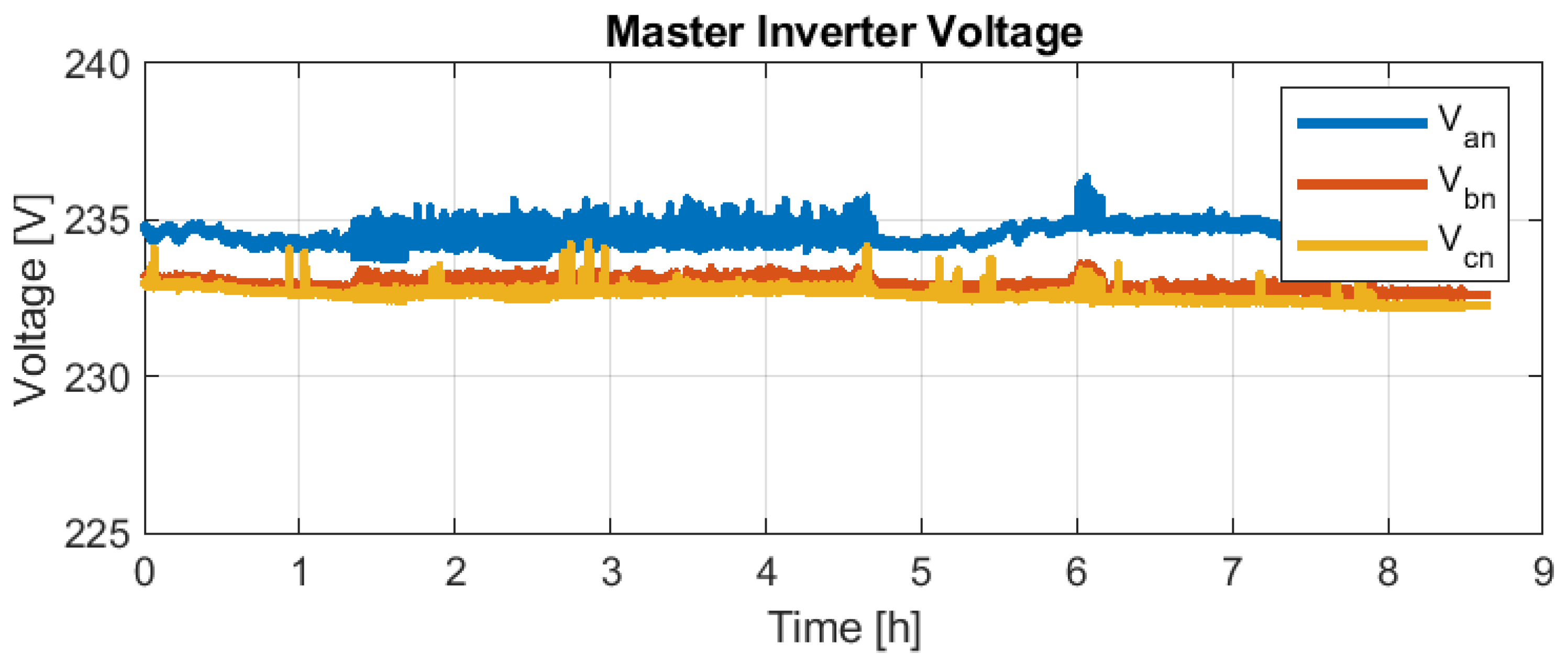
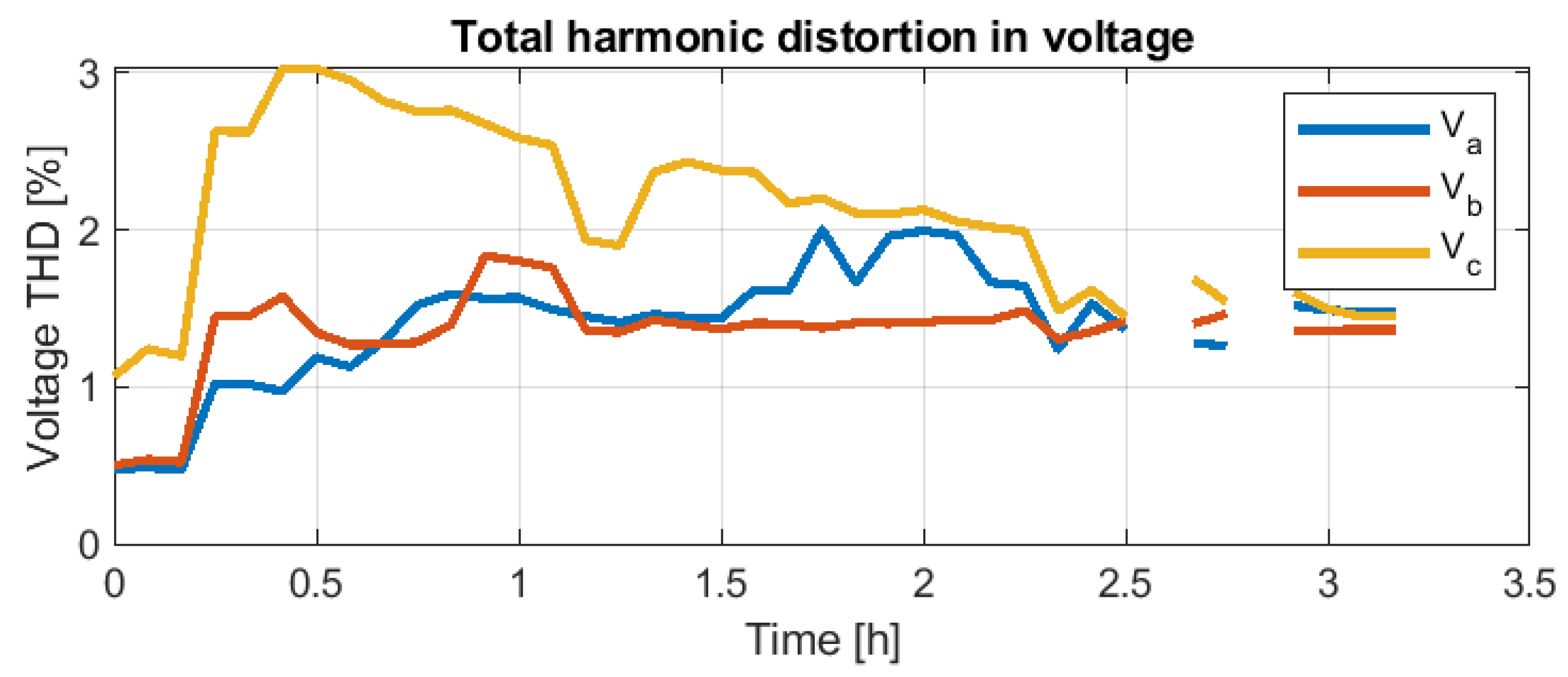
Figure 22 and
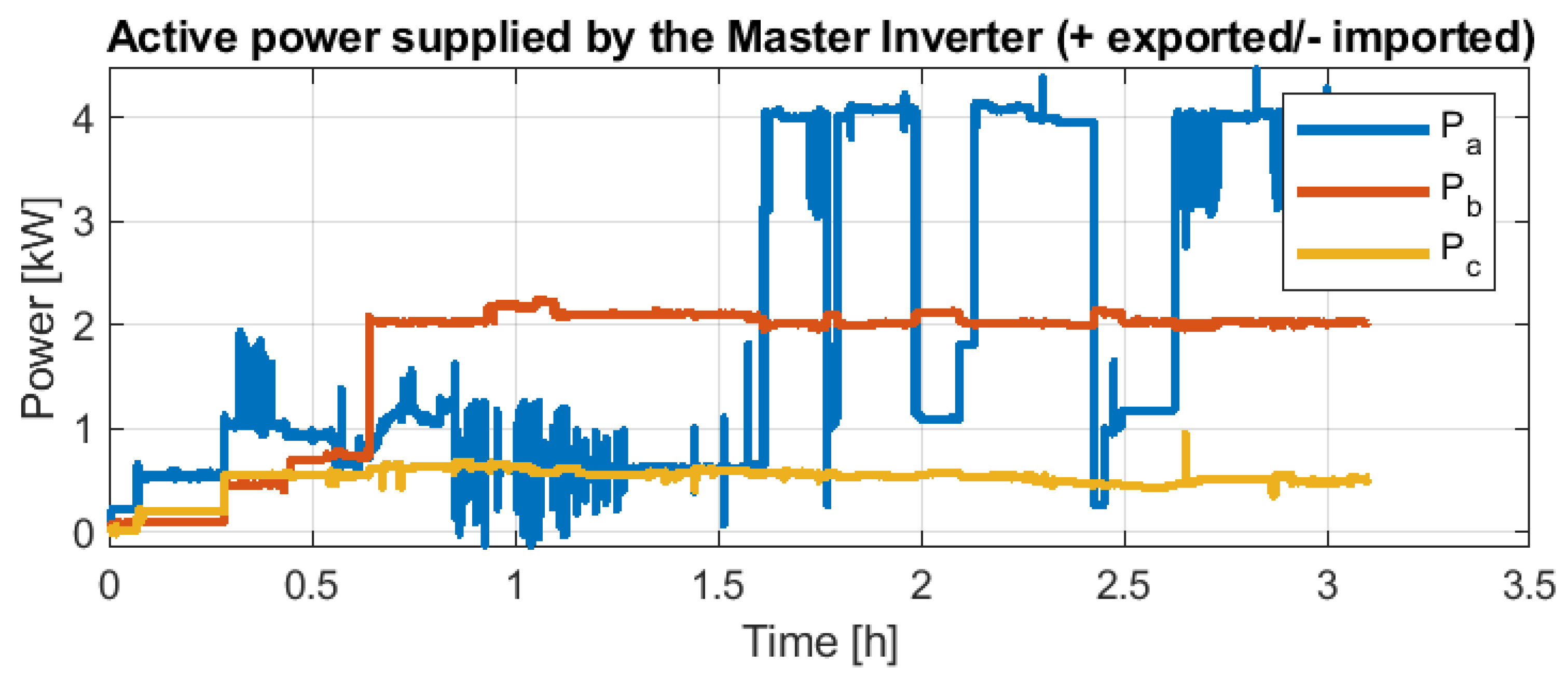
Figure 23 show the Master Inverter’s applied voltage and the exchanged active power, respectively. Furthermore,
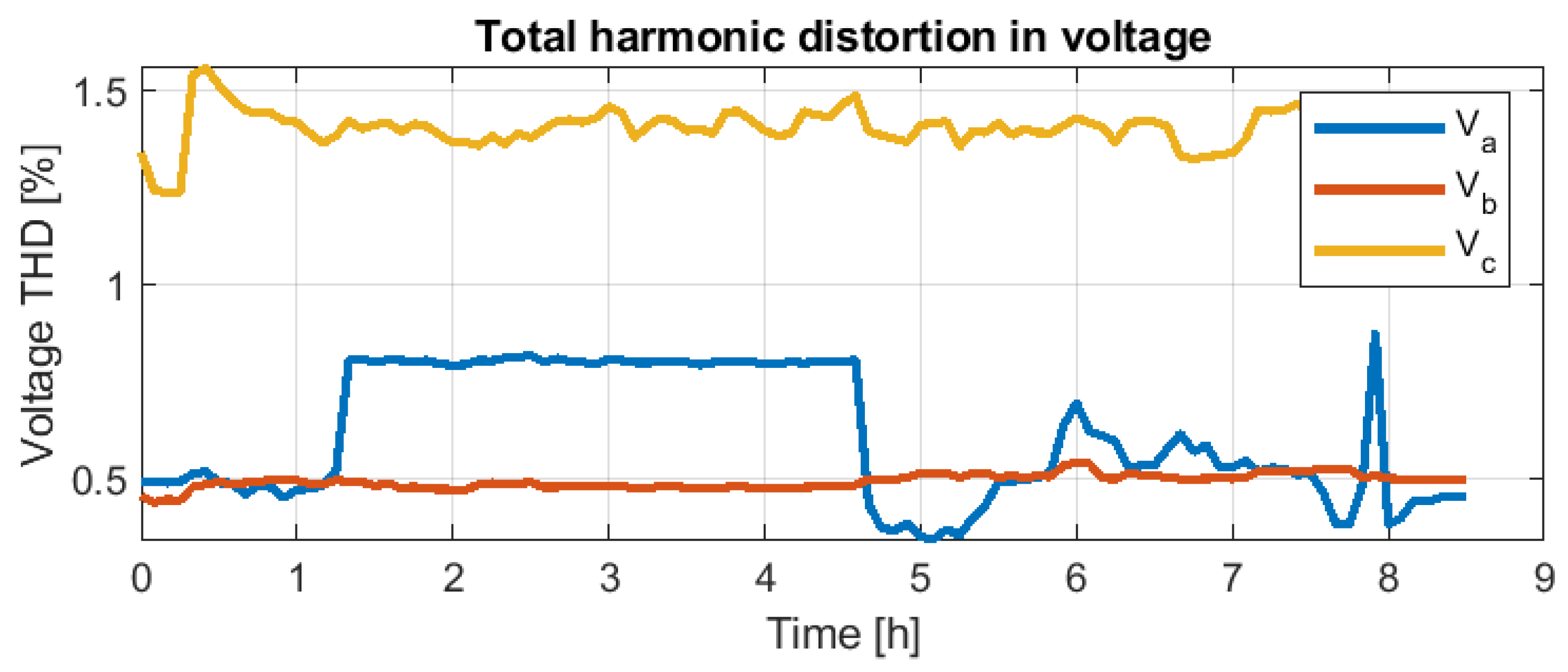
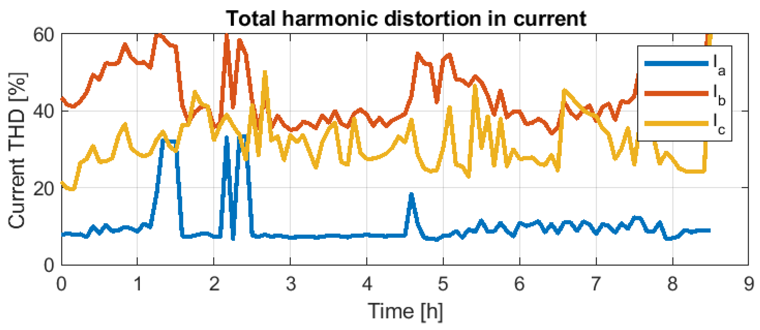
Figure 24 and
Figure 25 provide the total harmonic distortion (THD) for the voltage applied to the microgrid and the THD for currents’ consumption, respectively.
From
Figure 20 can be identified three periods:
Period 1—Time from 0 to 1.5 h (from 10:00 a.m. to 11:30 a.m.). This period can be classified as a low consumption period with low PV system participation due to the daytime hour.
During this period, the Master Inverter supplies energy for about one hour and a half, reaching an accumulated energy of 0.7 kWh. No other active sources are actively participating in the energy mix.
Figure 21 details how the Master Inverter reduces the frequency gradually because the second-life battery voltage is decreasing rapidly. This allows polling a request to the rest of the grid feeders, indicating that additional power is required.
Period 2—Time from 1.5 to 4.5 h (from 11:30 a.m. to 14:30 p.m.). During this period, the EV inverter starts to react to the frequency imposed by the Master Inverter. Consequently, as shown in
Figure 23, phase
a changes the power flow direction, meaning that the EV inverter starts to deliver power. This contribution is practically constant throughout the period, delivering about 4.5 kWh.
As the amount of consumption was still low (similar to Period 1), the surplus of power provided by the EV is partially used to recharge the second-life battery; refer to accumulated energy in
Figure 20. This is translated into a frequency increase, as shown in
Figure 21. Note also the oscillating delivered power in phase
c. This can be understood as the PV also contributing by intermittently delivering power.
Period 3—Time from 4.5 to 8.5 h(from 14:30 p.m. to 18:30 p.m.). From time 4.5 h on, as the frequency at the beginning of the period is 50.8 Hz, the EV inverter reduces its contribution. The PV system follows a similar pattern compared with Period 2.
Due to the reduction of EV inverter contribution, the consumption had to be covered partially by the second-life battery. This derives a frequency drift to 50 Hz, as shown in
Figure 21.
It should be detailed that even the Master Inverter requests more power at the end of this third period (from time 6 h on); these last two hours correspond to the last afternoon hours. This means low or almost null PV contribution. Moreover, the EV inverter has its logic. Thus, after delivering about 5 kWh during the last time, it did not follow the Master Inverter request, although it delivers some power.
From
Figure 24 and
Figure 25 can be validated that even in the case of high current THD (10–60%), the voltage provided by the Master Inverter is less than 2% THD. This 2% in voltage THD is better than the admissible 5% mentioned in IEEE-519 [
30].
5.1.2. Sunday, 7 October 2018
The scheduled loads were increased to a maximum of 5 kW/phase, covering 50% of the fair booths, due to the good results of the previous day. This was scheduled without changing any other part of the microgrid. Unfortunately, it was a cloudy and a bit rainy day. This situation, joined with the increase of booths to be supplied and a malfunction on the EV-inverter grid-feeder, propitiates that the Master Inverter should cover the total consumption for the whole day. Due to the context of the operation mentioned before, it was only possible to operate during 3.2 h.
Following the same structure as the previous day for data analysis,
Figure 26 and
Figure 27 show the energy and frequency followed profile.
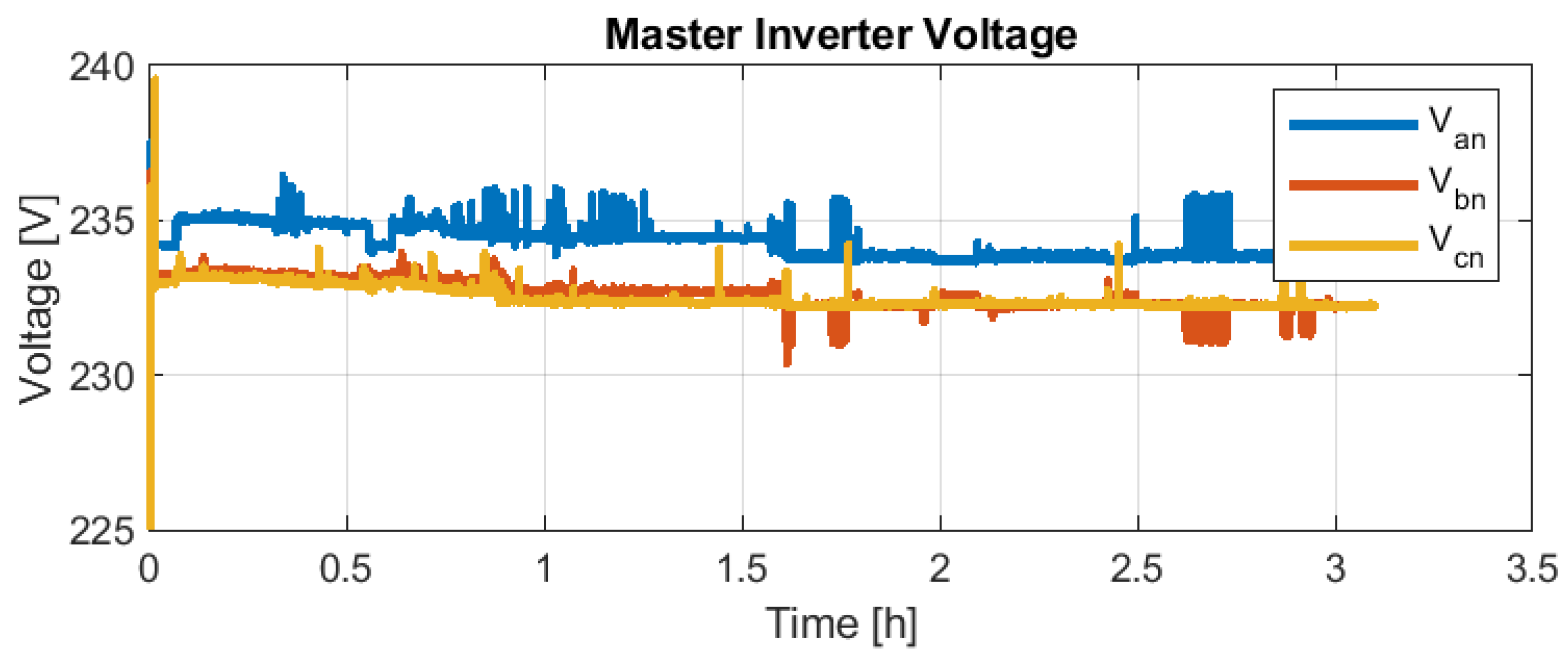
Figure 28 and
Figure 29 show the applied voltages and power supplied to the microgrid. Finally,
Figure 30 and
Figure 31 depict quality information about the voltage and current THDs.
It can be observed in
Figure 27 that the Master Inverter starts to request 100% feasible power from the other grid feeders in less than one hour. However, after 3 h, the central storage system was discharged, as no other active sources were available (about 14 kWh provided by the Master Inverter, as observed in
Figure 26).
Figure 30 and
Figure 31 validate again that even in the case of high current THD (5–55%), the voltage provided by the Master Inverter is less than 3%, being better than the admissible 5% mentioned in IEEE-519 [
30].
5.2. Expoelectric19 Results
The Expoelectric19 fair will be held in Barcelona on 2 and 3 November 2019 (from 10:00 a.m to 18:00 p.m approximately). For the system overview, refer to
Section 2—
Figure 2. As opposed to Expoelectric18, the Expoelectric19 experience aims to feed up to 80% of the booths from the beginning (the 20% missing corresponds to more than 1.5 kW/booth loads).
For the data analysis of Expoelectric19, it has been considered a power meter CEM-C20 (Circutor) for monitoring aggregated nodes by type (four in total). There is one power meter to monitor the Master Inverter, another to monitor both V2G chargers, one more to monitor the PV contribution and, finally, the other one to monitor the booth’s consumption. This metering distribution helps to understand the power flow in each situation. The analysis of the demand power management of the grid-feeding inverters using the AC frequency has been evaluated previously, according to the Expoelectric18 data. Thus, it has been excluded from this section.
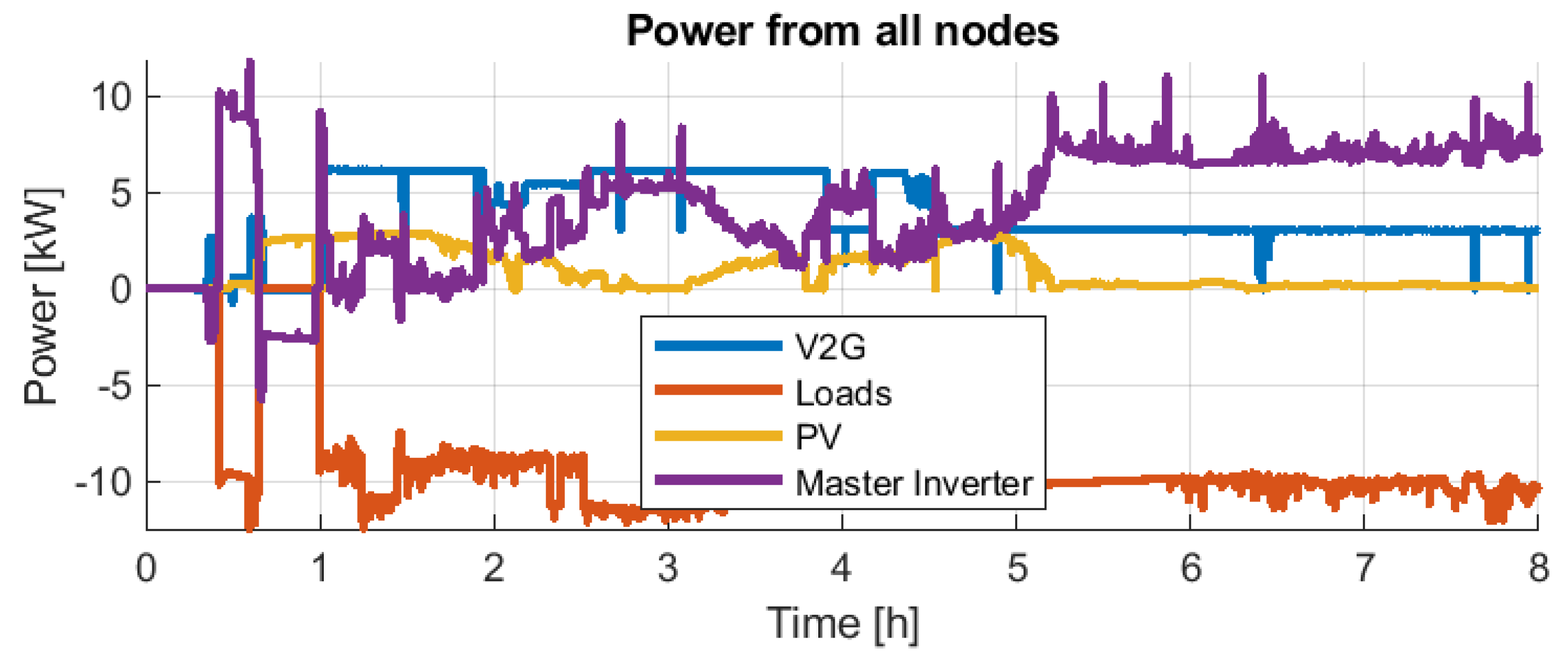
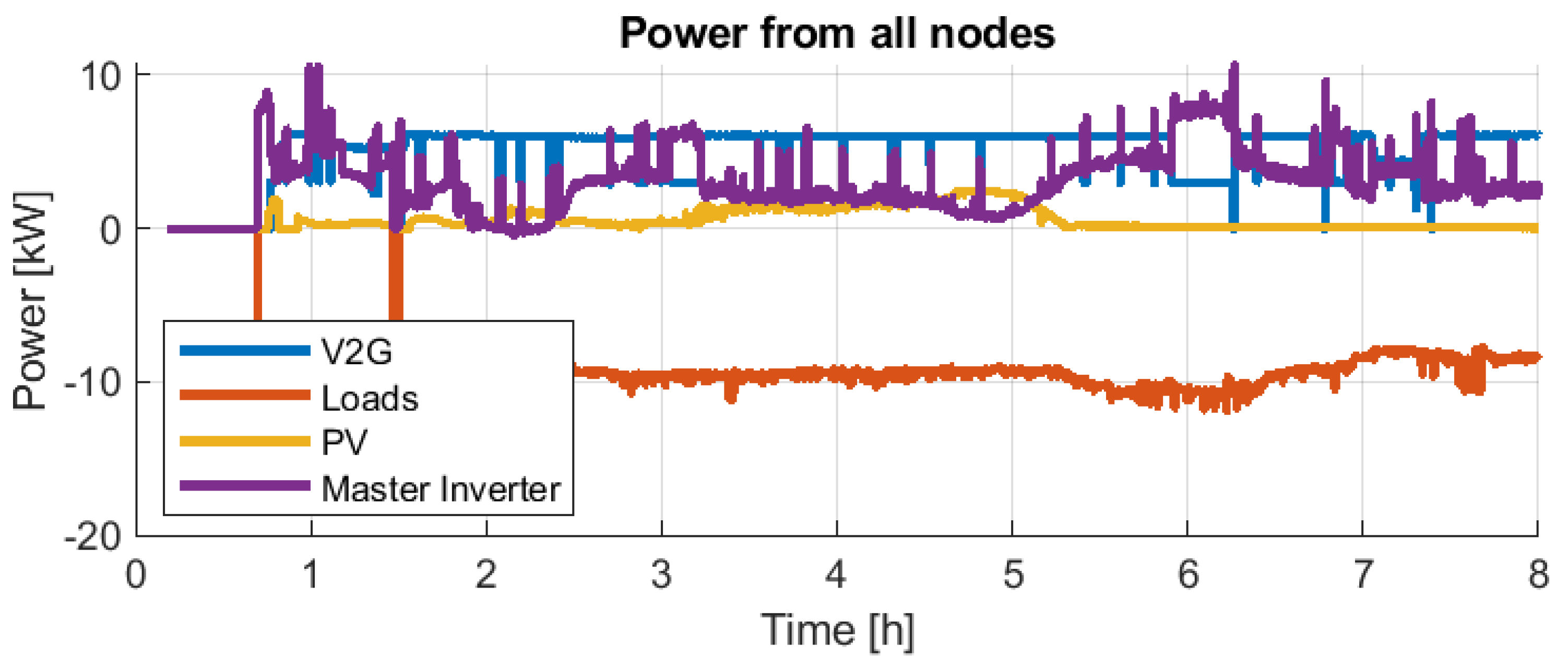
From
Figure 32 and
Figure 34, it can be observed that in both day experiences, there is an almost constant total consumption of about 10 kW. Furthermore, the PV contributes according to the irradiation availability, and the EV plus the V2G chargers almost always deliver full power. Thus, the Master Inverter delivers the difference. In both days’ experience, the Master Inverter supplied less than 35 kWh and only needed to contribute with a maximum of 10 kW eventually and less than 7 kW continuously.
The results explained in previous sections demonstrate that the Master converter proposed can manage the microgrid’s energy and power balance. Using frequency to manage the microgrid according to standard VDE-AR-N-4105 [
24] has shown promising results. However, it is not optimal because of the lack of communication between the different equipment in the microgrid.
6. Conclusions
Expoelectric18 and Expoelectric19 have been two live field experiences creating an isolated low voltage AC microgrid using renewables and storage. The presented operation of the microgrid is based on the VDE-AR-N-4105 standard, and frequency varies depending on the SoC of the battery of the Master Inverter, avoiding the use of any dedicated communication protocol and allowing the interconnection of different manufacturer equipment. The field test has shown that the proposed operation scheme is fully reliable in this type of isolated microgrid.
In addition, the FPR controller used to control the output voltage of the Master Inverter shows a very low voltage THD, even under heavy load unbalances or high demanding current THD loads.
Fault management in the microgrid has been designed according to the short-circuit power capability of the Main Inverter. In this sense, the Master Inverter includes an ideal virtual circuit breaker and short-circuit-proof mechanism to operate the microgrid in case of a grid fault safely. All safety and quality mechanisms have been tested in the laboratory. The results of this testing have shown that the Master Inverter can achieve these challenges successfully, including fault occurrence and clearance.
Up to four days of metering data have shown that it has been possible to feed a fair such as Expoelectric by participating in power electronics, locally distributed resources and second-life batteries without direct communications.
Expoelectric18 was the first-year experience and had to be considered a proof of concept. Saturday, November 6, data shows that it is possible to use coordination based on the AC frequency set by the Master Inverter for the power participation of the active sources. However, how the grid feeders implement VDE-AR-N-4105 is vital for correctly operating the whole system.
Expoelectric19 is an experience with previous edition knowledge. The participation of grid-feeders with more power involved ends with two days where the isolated microgrid exchanges satisfactorily about 70 kWh/day without blackouts. It should be remarked that the contribution of the Master Inverter is only about 50% maximum in terms of energy thanks to the coordination with the rest of the grid feeders.
Author Contributions
Conceptualization, D.H.-P., C.C.-A., O.G.-B., A.S.-A. and D.M.-M.; Data Curation, D.H.-P., C.C.-A., F.G.-L. and P.G.-F.; Formal analysis, D.H.-P. and C.C.-A.; Investigation, D.H.-P. and C.C.-A.; Methodology, D.H.-P. and C.C.-A.; Project administration, D.H.-P., C.C.-A. and O.G.-B.; Resources, Software, D.H.-P., C.C.-A., F.G.-L., P.G.-F. and M.P.-G.; Supervision, O.G.-B., S.G.-A. and D.M.-M.; Validation, D.H.-P., C.C.-A. and P.G.-F.; Visualization, D.H.-P., C.C.-A., F.G.-L. and P.G.-F.; Writing—original draft preparation, D.H.-P. and C.C.-A.; Writing—review and editing, D.H.-P., C.C.-A., O.G.-B. and D.M.-M. All authors have read and agreed to the published version of the manuscript.
Funding
This research received no external funding.
Institutional Review Board Statement
Not applicable.
Informed Consent Statement
Not applicable.
Data Availability Statement
Not applicable.
Conflicts of Interest
The authors declare no conflict of interest.
References
- Saeed, M.H.; Fangzong, W.; Kalwar, B.A.; Iqbal, S. A Review on Microgrids’ Challenges & Perspectives. IEEE Access 2021, 9, 166502–166517. [Google Scholar] [CrossRef]
- Ahmed, M.; Meegahapola, L.; Vahidnia, A.; Datta, M. Stability and Control Aspects of Microgrid Architectures–A Comprehensive Review. IEEE Access 2020, 8, 144730–144766. [Google Scholar] [CrossRef]
- Solar Energy Applications in Houses, Smart Cities and Microgrids; Callejo, L.H. (Ed.) MDPI: Basel, Switzerland, 2020. [Google Scholar] [CrossRef] [Green Version]
- Hatziargyriou, N.; Asano, H.; Iravani, R.; Marnay, C. Microgrids. IEEE Power Energy Mag. 2007, 5, 78–94. [Google Scholar] [CrossRef]
- Feng, W.; Jin, M.; Liu, X.; Bao, Y.; Marnay, C.; Yao, C.; Yu, J. A review of microgrid development in the United States—A decade of progress on policies, demonstrations, controls, and software tools. Appl. Energy 2018, 228, 1656–1668. [Google Scholar] [CrossRef]
- Rey, J.M.; Vera, G.A.; Acevedo-Rueda, P.; Solano, J.; Mantilla, M.A.; Llanos, J.; Sáez, D. A Review of Microgrids in Latin America: Laboratories and Test Systems. IEEE Lat. Am. Trans. 2022, 20, 1000–1011. [Google Scholar] [CrossRef]
- Onipoh, K.; Zaidi, S.R. Overview and Performance Evaluation of Vehicle-to-Grid (V2G) Power Transactions. In Proceedings of the 2021 International Conference on Electrical, Computer, Communications and Mechatronics Engineering (ICECCME), Mauritius, Mauritius, 7–8 October 2021; pp. 1–4. [Google Scholar] [CrossRef]
- Hartono, B.S.; Budiyanto, Y.; Setiabudy, R. Review of microgrid technology. In Proceedings of the 2013 International Conference on Quality in Research, QiR 2013—In Conjunction with ICCS 2013: The 2nd International Conference on Civic Space, Yogyakarta, Indonesia, 25–28 June 2013; pp. 127–132. [Google Scholar] [CrossRef]
- Li, F.; Lin, Z.; Qian, Z.; Wu, J. Active DC bus signaling control method for coordinating multiple energy storage devices in DC microgrid. In Proceedings of the 2017 IEEE Second International Conference on DC Microgrids (ICDCM), Nuremburg, Germany, 27–29 June 2017; pp. 221–226. [Google Scholar] [CrossRef] [Green Version]
- Singhal, A.; Vu, T.L.; Du, W. Consensus Control for Coordinating Grid-Forming and Grid-Following Inverters in Microgrids. IEEE Trans. Smart Grid 2022, 13, 4123–4133. [Google Scholar] [CrossRef]
- Bani-Ahmed, A.; Weber, L.; Nasiri, A.; Hosseini, H. Microgrid communications: State of the art and future trends. In Proceedings of the IEEE 3rd International Conference on Renewable Energy Research and Applications, ICRERA 2014, Milwaukee, WI, USA, 19–22 October 2014; pp. 780–785. [Google Scholar] [CrossRef]
- Perez-Guzman, R.E.; Salgueiro, Y.; Rivera, M.; Munoz, J.; Toledo, S. Modelling communication network for intelligent applications in microgrids-Part i. In Proceedings of the IEEE ICA-ACCA 2018—IEEE International Conference on Automation/23rd Congress of the Chilean Association of Automatic Control, Concepcion, Chile, 17–19 October 2019; pp. 15–20. [Google Scholar] [CrossRef]
- Nayak, K.; Mohanty, R.; Pradhan, A.K. Testing a communication assisted protection scheme for AC microgrid in a laboratory setup. In Proceedings of the 2017 6th International Conference on Computer Applications In Electrical Engineering-Recent Advances (CERA), Roorkee, India, 5–7 October 2017; pp. 286–290. [Google Scholar] [CrossRef]
- Gutierrez-Rojas, D.; Nardelli, P.H.J.; Mendes, G.; Popovski, P. Review of the State of the Art on Adaptive Protection for Microgrids Based on Communications. IEEE Trans. Ind. Inform. 2021, 17, 1539–1552. [Google Scholar] [CrossRef]
- Zhang, D. Issues on load shedding in a microgrid operated at constant frequency. In Proceedings of the 2017 20th International Conference on Electrical Machines and Systems (ICEMS), Sydney, Australia, 11–14 August 2017; pp. 1–5. [Google Scholar] [CrossRef]
- Kwasinski, A. Advanced power electronics enabled distribution architectures: Design, operation, and control. In Proceedings of the IEEE 8th International Conference on Power Electronics—ECCE Asia, Jeju, Republic of Korea, 30 May–3 June 2011; pp. 1484–1491. [Google Scholar] [CrossRef]
- Hirsch, A.; Parag, Y.; Guerrero, J. Microgrids: A review of technologies, key drivers, and outstanding issues. Renew. Sustain. Energy Rev. 2018, 90, 402–411. [Google Scholar] [CrossRef]
- Hooshyar, A.; Iravani, R. Microgrid Protection. Proc. IEEE 2017, 105, 1332–1353. [Google Scholar] [CrossRef]
- Heredero-Peris, D.; Chillón-Antón, C.; Pagès-Giménez, M.; Montesinos-Miracle, D.; Santamaría, M.; Rivas, D.; Aguado, M. An enhancing fault current limitation hybrid droop/V-f control for grid-tied four-wire inverters in AC microgrids. Appl. Sci. 2018, 8, 1725. [Google Scholar] [CrossRef] [Green Version]
- Almutairy, I.; Alluhaidan, M. Protecting a low voltage DC microgrid during short-circuit using solid-state switching devices. In Proceedings of the 2017 IEEE Green Energy and Smart Systems Conference (IGESSC), Long Beach, CA, USA, 6–7 November 2017; pp. 1–6. [Google Scholar] [CrossRef]
- Du, W.; Lasseter, R.; Khalsa, A. Survivability of Autonomous Microgrid during Overload Events. IEEE Trans. Smart Grid 2020, 10, 3515–3524. [Google Scholar] [CrossRef]
- Oureilidis, K.O.; Demoulias, C.S. A Fault Clearing Method in Converter-Dominated Microgrids With Conventional Protection Means. IEEE Trans. Power Electron. 2016, 31, 4628–4640. [Google Scholar] [CrossRef]
- Ahamed, I.; Vydeeswaran, K.; Swathika, O.G. Microgrid fault clearance with linear programming algorithms. In Proceedings of the 2017 2nd International Conference on Communication and Electronics Systems (ICCES), Coimbatore, India, 19–20 October 2017; pp. 42–46. [Google Scholar] [CrossRef]
- VDE. Power Generating Plants in the Low Voltage Grid (VDE-AR-N 4105); Technical Report; VDE: Offenbach am Main, Germany, 2019. [Google Scholar]
- Malaczek, M.; Wasiak, I. Forming a microgrid to islanded operation as a mean to improve quality of supply in low voltage networks with distributed generation. In Proceedings of the 2018 18th International Conference on Harmonics and Quality of Power (ICHQP), Ljubljana, Slovenia, 13–16 May 2018; pp. 1–6. [Google Scholar] [CrossRef]
- Heredero-Peris, D.; Chillón-Antón, C.; Sánchez-Sánchez, E.; Montesinos-Miracle, D. Fractional proportional-resonant current controllers for voltage source converters. Electr. Power Syst. Res. 2019, 168, 20–45. [Google Scholar] [CrossRef]
- Hoffmann, A.; Fleckenstein, M.; Balzer, G.; Hartkopf, T. Grid services with PV-converters in distribution systems. In Proceedings of the ISGT 2014, Washington, DC, USA, 19–22 February 2014; pp. 1–5. [Google Scholar] [CrossRef]
- Armstorfer, A.; Biechl, H.; Rosin, A. Analysis of Black Start Strategies for Microgrids with Renewable Distributed Generation. In Proceedings of the IECON 2019—45th Annual Conference of the IEEE Industrial Electronics Society, Lisbon, Portugal, 14–17 October 2019; Volume 1, pp. 2121–2125. [Google Scholar] [CrossRef]
- Kalathi, S.; Raveendhra, D.; Narasimha Raju, B. Efficient Single-Phase Grid Connected Transformer-less Inverter with Active and Reactive Power Control. In Proceedings of the 2022 IEEE 2nd International Conference on Sustainable Energy and Future Electric Transportation (SeFeT), Hyderabad, India, 4–6 August 2022; pp. 1–7. [Google Scholar] [CrossRef]
- IEEE Recommended Practice and Requirements for Harmonic Control in Electric Power Systems; IEEE Std 519-2014 (Revision of IEEE Std 519-1992); IEEE: Piscataway, NJ, USA, 2014; pp. 1–29. [CrossRef]
Figure 1.
System overview of the microgrid implemented in Expoelectric18.
Figure 1.
System overview of the microgrid implemented in Expoelectric18.
Figure 2.
System overview of the microgrid implemented in Expoelectric19.
Figure 2.
System overview of the microgrid implemented in Expoelectric19.
Figure 3.
General control scheme for the Master Inverter.
Figure 3.
General control scheme for the Master Inverter.
Figure 4.
Master Inverter output voltage response against a sudden connection of a non-linear load.
Figure 4.
Master Inverter output voltage response against a sudden connection of a non-linear load.
Figure 5.
Demand power management of the grid-feeding inverters depending on the frequency and SoC of the battery of the Master Inverter.
Figure 5.
Demand power management of the grid-feeding inverters depending on the frequency and SoC of the battery of the Master Inverter.
Figure 6.
Discharge test conducted for rated 30 and 60 kWh main storage second-life battery used at Expoelectric18 and Expoelectric19.
Figure 6.
Discharge test conducted for rated 30 and 60 kWh main storage second-life battery used at Expoelectric18 and Expoelectric19.
Figure 7.
Control schemes of the sinusoidal wave short-circuit proof algorithm.
Figure 7.
Control schemes of the sinusoidal wave short-circuit proof algorithm.
Figure 8.
Microgrid voltage under a low impedance single-phase short circuit (Current: 20 A/div, Voltage 120 V/div).
Figure 8.
Microgrid voltage under a low impedance single-phase short circuit (Current: 20 A/div, Voltage 120 V/div).
Figure 9.
Microgrid voltage under a low impedance two-phase short circuit (Current: 50 A/div, Voltage 120 V/div).
Figure 9.
Microgrid voltage under a low impedance two-phase short circuit (Current: 50 A/div, Voltage 120 V/div).
Figure 10.
Microgrid voltage under a low impedance three-phase short circuit.
Figure 10.
Microgrid voltage under a low impedance three-phase short circuit.
Figure 11.
Virtual circuit breaker trip curve implemented in the Master Inverter. (Green trip curve).
Figure 11.
Virtual circuit breaker trip curve implemented in the Master Inverter. (Green trip curve).
Figure 12.
Virtual circuit breaker response under an overload situation.
Figure 12.
Virtual circuit breaker response under an overload situation.
Figure 13.
Detail of the Master Inverter power electronics.
Figure 13.
Detail of the Master Inverter power electronics.
Figure 14.
FCC truck at Expoeletric18.
Figure 14.
FCC truck at Expoeletric18.
Figure 15.
Carport with PV panels at Expoeletric18.
Figure 15.
Carport with PV panels at Expoeletric18.
Figure 16.
Master Inverter and main storage system (Electric van) at Expoelectric18.
Figure 16.
Master Inverter and main storage system (Electric van) at Expoelectric18.
Figure 17.
V2G connected to the used Nissan Leafs at Expoelectri19.
Figure 17.
V2G connected to the used Nissan Leafs at Expoelectri19.
Figure 18.
PV installation and support battery at Expoelectric19.
Figure 18.
PV installation and support battery at Expoelectric19.
Figure 19.
Booths at Expoelectric.
Figure 19.
Booths at Expoelectric.
Figure 20.
Energy exchanged by the Master Inverter on 6 October (computed in intervals of 5 min).
Figure 20.
Energy exchanged by the Master Inverter on 6 October (computed in intervals of 5 min).
Figure 21.
Frequency applied by the Master Inverter on 6 October (according to
Figure 5).
Figure 21.
Frequency applied by the Master Inverter on 6 October (according to
Figure 5).
Figure 22.
Voltages applied by the Master Inverter on 6 October.
Figure 22.
Voltages applied by the Master Inverter on 6 October.
Figure 23.
Power exchanged by the Master Inverter on 6 October.
Figure 23.
Power exchanged by the Master Inverter on 6 October.
Figure 24.
Total harmonic distortion (THD) for the voltages applied by the Master Inverter on 6 October.
Figure 24.
Total harmonic distortion (THD) for the voltages applied by the Master Inverter on 6 October.
Figure 25.
Total harmonic distortion (THD) for the load’s current on 6 October.
Figure 25.
Total harmonic distortion (THD) for the load’s current on 6 October.
Figure 26.
Energy exchanged by the Master Inverter on 7 October (computed in intervals of 5 min).
Figure 26.
Energy exchanged by the Master Inverter on 7 October (computed in intervals of 5 min).
Figure 27.
Frequency applied by the Master Inverter on 7 October (according to
Figure 5).
Figure 27.
Frequency applied by the Master Inverter on 7 October (according to
Figure 5).
Figure 28.
Voltages applied by the Master Inverter on 7 October.
Figure 28.
Voltages applied by the Master Inverter on 7 October.
Figure 29.
Power exchanged by the Master Inverter on 7 October.
Figure 29.
Power exchanged by the Master Inverter on 7 October.
Figure 30.
Total harmonic distortion (THD) for the voltages applied by the Master Inverter on 7 October. Missing values from 2.5 h to 3 h are due to missing data from meters.
Figure 30.
Total harmonic distortion (THD) for the voltages applied by the Master Inverter on 7 October. Missing values from 2.5 h to 3 h are due to missing data from meters.
Figure 31.
Total harmonic distortion (THD) for the load’s current on 7 October. Missing values from 2.5 h to 3 h are due to missing data from meters.
Figure 31.
Total harmonic distortion (THD) for the load’s current on 7 October. Missing values from 2.5 h to 3 h are due to missing data from meters.
Figure 32.
Power for each node on 2 November.
Figure 32.
Power for each node on 2 November.
Figure 33.
Energy for each node on 2 November.
Figure 33.
Energy for each node on 2 November.
Figure 34.
Power for each node on 3 November.
Figure 34.
Power for each node on 3 November.
Figure 35.
Energy for each node on 3 November.
Figure 35.
Energy for each node on 3 November.
Table 1.
Proposed ideal trip curve.
Table 1.
Proposed ideal trip curve.
| Current Range [A] | Trip Curve Time [s] |
|---|
| 0.00–14.9 | ∞ |
| 15.0–19.9 | 60 |
| 20.0–24.9 | 8 |
| 25.0–29.9 | 3 |
| 30.0–34.9 | 1.5 |
| 35.0–39.9 | 0.5 |
| 40.0–44.9 | 0.2 |
| 45.0–49.9 | 0.1 |
| >50.0 | <0.1 |
| Disclaimer/Publisher’s Note: The statements, opinions and data contained in all publications are solely those of the individual author(s) and contributor(s) and not of MDPI and/or the editor(s). MDPI and/or the editor(s) disclaim responsibility for any injury to people or property resulting from any ideas, methods, instructions or products referred to in the content. |
© 2023 by the authors. Licensee MDPI, Basel, Switzerland. This article is an open access article distributed under the terms and conditions of the Creative Commons Attribution (CC BY) license (https://creativecommons.org/licenses/by/4.0/).


 ,
, 


