Proceeding Paper

Use of Bonded Joints for Fastening Sheet-Metal Components to Contemporary Facades Fitted with an External Thermal Insulation Composite System with Thin-Layer Acrylic Plaster †

Faculty of Civil Engineering, Brno University of Technology, Veveří 331/95, 602 00 Brno, Czech Republic
*
Author to whom correspondence should be addressed.
Presented at the 10th MATBUD’2023 Scientific-Technical Conference “Building Materials Engineering and Innovative Sustainable Materials”, Cracow, Poland, 19–21 April 2023.
Mater. Proc. 2023, 13(1), 36; https://doi.org/10.3390/materproc2023013036
Published: 16 February 2023
(This article belongs to the Proceedings of 10th MATBUD’2023 Scientific-Technical Conference)

Abstract

:
This paper deals with the issue of fastening sheet-metal components on the facades of contemporary buildings that are massively insulated with external thermal insulation composite systems. This research focused on facades with thin-layer acrylic plaster and sheet-metal components made of aluminium, copper and hot-dipped galvanized sheet metal. Two different test methods and test sample geometries were used to determine the most critical aspects for the studied application sectors. Surprisingly high tensile properties as well as shear stresses in the bonded joints were recorded for all the selected combinations. The presented results confirmed the assumed benefits for the construction industry and the future practical use of this technology in construction, although the durability of a bonded joint will always depend mainly on the quality of the bonded substrate.

1. Introduction

Saving energy has been a major issue in recent years as part of the efforts to maintain the sustainable development of society. In 2022, the situation in Europe changed dynamically due to the military conflict in Ukraine, which resulted in the virtual collapse of energy markets and an uncontrollable rise in gas and electricity prices. Countries were forced to search for solutions in an unprecedented situation and the pressure for energy saving was intensified. The greatest potential of the construction industry lies in savings in heating buildings [1]. In new buildings, the desire to reduce heat loss is reflected both in the design of the building structure [2] and in the thermal parameters of the structures. However, the greatest potential, regarding the number of buildings, lies in existing structures, where the most common way of improving the energy balance has been additional insulation [3]. This can be implemented in two ways. The first is the use of suspended facade systems, which consist of a load-bearing (usually aluminium) structure, mineral wool thermal insulation, a windproof diffusion-open membrane, a ventilated air gap and a facing cladding board [4,5]. The second option is external thermal insulation using a composite system that is in full contact with the original surface of the facade and consists of thermal insulation (most often expanded polystyrene or mineral wool, or other materials that are used less frequently) and reinforcing layers of cement screed with fibreglass mesh, coloured primer and coloured thin-layer plaster [6,7]. Both options include a thick layer of thermal insulation that can be sized as required to provide the desired energy savings. Each of the two options has both advantages and disadvantages. In general, however, contact insulation is significantly more widespread. This is primarily due to its lower cost, which represents approximately one-third of a suspended ventilated facade system. The authors of this paper focused on the issue of sheet-metal facade components in contact-insulated facade systems, where secure fastening to the substrate becomes increasingly difficult due to the increasing thickness of the thermal insulation.
Currently, 200 mm thick layers of thermal insulation are common, and 300 mm thick insulation is not an exception. These surfaces are largely unsuitable for plumbing work, mainly due to the impossibility of firm fastening, as the outer plaster layer is too thin, and the insulation itself is not a load-bearing substrate. While there are system solutions for connecting sheet-metal components to multi-layer plaster, e.g., parapet connection profiles with integrated adhesive surfaces for bonding metal parapets or connection profiles for inserting vertical facade flashings, these are always components intended to be fitted during the installation of the insulation system. Using these solutions requires precise coordination during the construction process. Moreover, they are not always applicable as they do not allow the fitting of sheet-metal structures during additional work onto older, previously insulated facades. This article deals with the issue of fastening sheet-metal components by bonding them to the surface of thin-layer plaster. It presents an initial series of tests to verify the perspectives of this technology for further research. The technology of bonding sheet-metal components to thin-layer plaster, if properly validated, would be widely applicable, even outside the field of contact thermal insulation systems.

2. Materials and Methods

2.1. Materials

Materials commonly used for sheet-metal components such as aluminium alloy, copper alloy and hot-dipped galvanized steel were tested. These materials are used in the form of thin sheets on construction sites; however, this research required the production of solid circular plates (hereinafter referred to as targets) and strips to be bonded to the substrate. The metallic materials used were aluminium alloy EN AW-2011 according to the EN 573-3 standard [8] with a tensile strength of 295.0 MPa and a yield strength of 195.0 MPa, copper alloy CW004A-R250—SH (Cu-ETP) according to the EN 13,601 standard [9] with a tensile strength of 250.0 MPa and a yield strength of 200.0 MPa, and hot-dipped galvanized steel brand S235JR (1.0038) according to the EN 10025-2 standard [10] with a tensile strength of min. 360.0 MPa and a yield strength of 235.0 MPa. The thixotropic silane modified polymer adhesive ARDEX CA 20 P for external applications produced by Ardex Baustoff GmbH was chosen for bonding to the substrate. No mechanical properties were provided by the manufacturer. The following materials were used for the production of the solid plasterboard test specimens for bonding the metal tear-off elements:
  • White pasty structural acrylic dispersion plaster with the brand name PROFI AKRYLATPUTZ produced by the manufacturer Profibaustoffe CZ, s.r.o., with a bond strength of min. 0.30 MPa;
  • Universal primer coating used under the white pasty plaster with the brand name PROFI UNI Putzgrund produced by the manufacturer Profibaustoffe CZ, s.r.o., with a styrene–acrylate binder;
  • An adhesive and screed compound for facade thermal insulation boards with the brand name PROFI UNI AM produced by the manufacturer Profibaustoffe CZ, s.r.o., with cement binder and a bonding strength to the solid substrate of min. 0.25 MPa;
  • Fibreglass fabric for screed compound with the brand name R117 A101 produced by Saint-Gobain Vertex, s.r.o., with a tensile strength of 2100 N/50 mm;
  • A smooth-surfaced cement-bonded particleboard with a thickness of 16 mm with the brand name CETRIS BASIC produced by the manufacturer CIDEM Hranice, a.s., with a transverse tensile strength of min. 0.63 MPa.

2.2. Methods

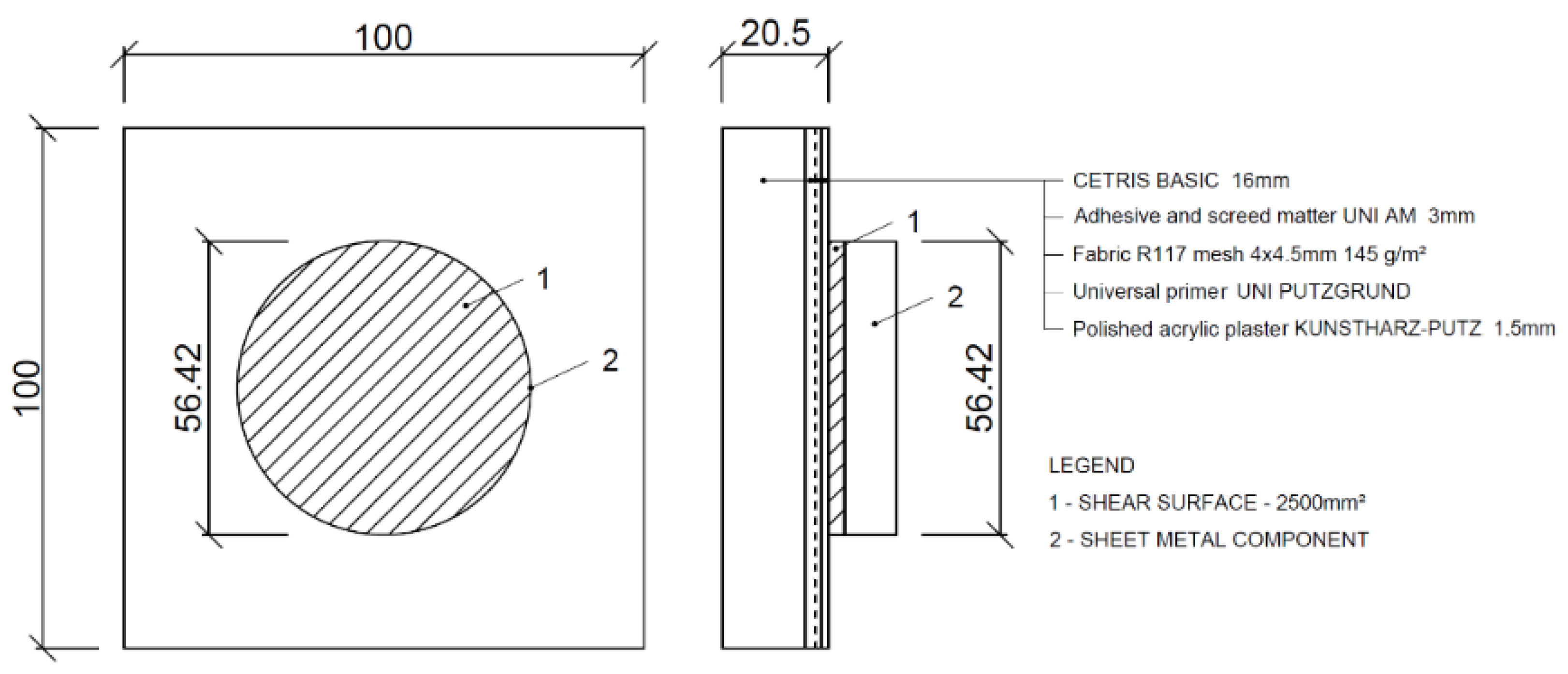
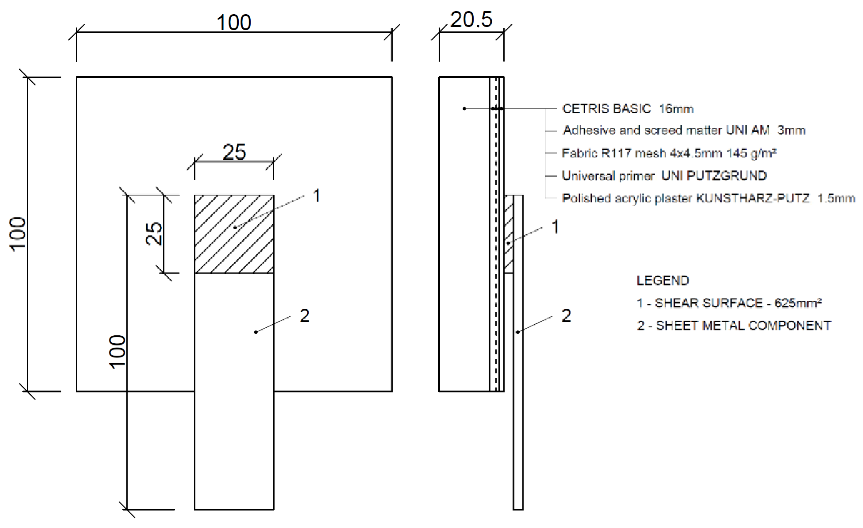
2.2.1. Preparation of Test Specimens

The test specimens consisted of a base plate, adhesive and a metal target of a circular shape with a bonding area of 2500 mm2 for the tensile tests and a metal strip of 100 × 25 mm with a bonding area of 625 mm2 for the shear tests. The base plate consisted of a layer that corresponded to the actual composition used in facades with contact insulation. The soft and easily deformable thermal insulator was replaced by a solid cement-bonded particleboard for laboratory purposes. The intention was to measure only the deformation of the tested adhesive without the undesired influence of any deformation of the thermal insulation. It was assumed that the adhesive would be torn off either in the plaster or in the screed. The cement-bonded particleboards were cut into 100 × 100 mm squares from a production size of 3350 × 1250 mm, and then cement screed with a thickness of 3 mm was applied to them in two layers. A fibreglass fabric was fitted between the first and second layers of the cement screed. After the screed had cured the surface was coated with a primer, and a final 1.5 mm thick layer of acrylic plaster, was applied. The composition of the test specimen for the tensile test is shown in Figure 1, and in Figure 2 the test specimen for the shear test can be seen. Close attention was paid to the production of the bonded joint, where a constant adhesive thickness of 3 mm had to be maintained. Inaccuracies of this basic parameter would adversely affect the measurement results [11].

2.2.2. Adhesion Tests
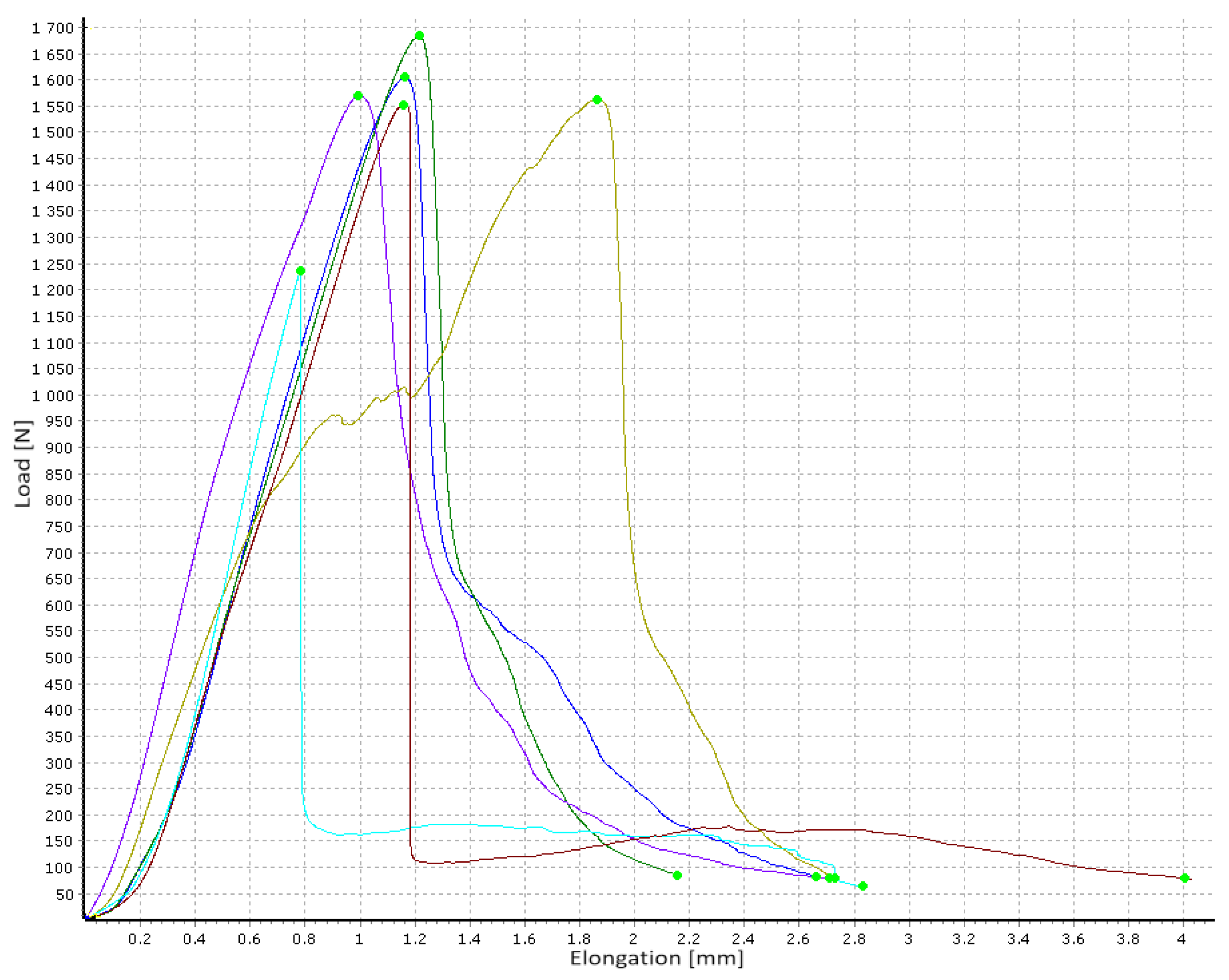
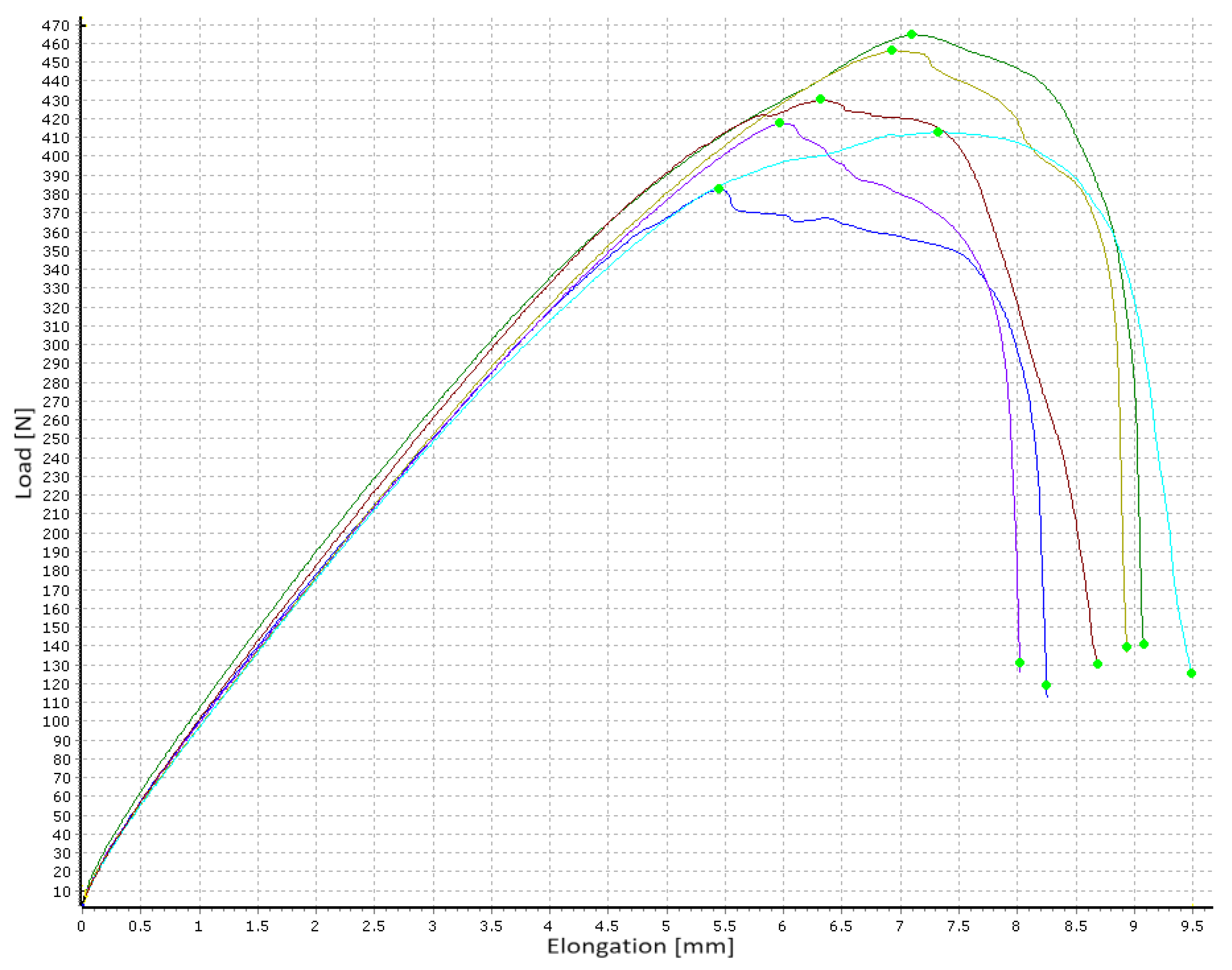
The tests were carried out on a LaborTech E.2 measuring device fitted with L06 vice jaws under normal laboratory conditions. The adhesion tests included both tensile and shear stresses. The basis of both the chosen test methods was the recording of the force course required to tear the adhered metal component of the substrate as a function of the elongation of the adhesive under testing. The loading was carried out at a rate of 5 mm per minute until failure, defined by a drop in force to 5% of the maximum achieved force for the tensile test and 30% for the shear test. The most important values for the evaluation were the maximum achieved force F (in N) and the corresponding elongation Δl (in mm). The tensile test was based on the procedure defined by the Czech technical standard ČSN 732,577 [12]. The principle of the test was to measure the force required to break away from the adhering body by tension applied perpendicular to the substrate. The tensile strength σadh (in MPa) was subsequently calculated according to the following relation:
σ a d h = F A = F 2500
The shear test was based on the procedure defined by the European technical standard EN 1465 [13]. The principle of the test was to measure the tensile force acting parallel to the surface of the bonded joint. The shear adhesion (in MPa) was calculated according to the formula:
τ = F A = F 625
The elongation (in %) was subsequently calculated from the increment of the length Δl (in mm) to the original length l (in mm):
ε = Δ l l 100

3. Results

The results were used to generate a number of charts showing the dependence of the elongation Δl on the applied force F. An example of a chart for the tensile test is shown in Figure 3, and an example of a chart for the shear test is in Figure 4.
The data from the deformation diagrams were tabulated in a clear way, with the decisive point for the evaluation being the maximum tensile or shear force and the corresponding elongation. Based on this data, the tensile adhesion σadh was calculated according to Formula (1), the shear adhesion τ was calculated according to Formula (2) and the elongation ε for both tensile and shear adhesion was calculated according to Formula (3). Statistical evaluation was performed for all the calculated parameters in the form of calculating the standard deviation sx and the coefficient of variation vx. The tensile test results can be seen in Table 1, and the shear test results are presented in Table 2.
A comparison of the adhesion and elongation in both tests can be seen in Figure 5. Possible types of destruction are shown in Figure 6. The most common type of destruction in the adhesion tests was the tearing of the metal target or strip, including the adhesive from the plaster surface. The second most common type of destruction was the tearing of the plaster, including the covering layer of the screed to the layer of the reinforcing fibreglass fabric. The least common destruction type presented only in copper strips in the shear test was the peeling of the adhesive from the copper material.

4. Discussion

For the steel and aluminium components, no metal came off the adhesive in any of the measurements; the destruction always occurred in the underlying plaster. In the case of the copper alloy, a difference was determined between the tensile and shear tests. While in the tensile test the adhesive was torn off the plaster in all cases, in the shear test, on the other hand, all the measurements showed a complete peeling of the adhesive from the copper surface, and only in one case did a partial peeling of the adhesive from the copper surface combined with destruction in the plaster occur, as can be seen in Figure 5. The declared strength of the plaster by the manufacturer was 0.3 MPa. The real values of the observed tensile and shear adhesive strengths essentially exceed this value two-fold, which was clearly due to the higher strength of the plaster and its inherent adhesion to the underlying screed. In terms of the measured data, there was no significant difference in whether the destruction occurred in the surface thin-layer plaster or the screed, and the values of the measured forces and the calculated stresses were similar. However, lower values were obtained in the case of copper in the shear test, where the destruction occurred almost exclusively by peeling off the copper strip.
In addition to the tests of the bonded joint between the metal element and the plaster substrate, the tensile and shear properties of the adhesive itself were measured. The measurements were carried out using a standard tensile and shear test, where the aluminium targets and strips were bonded together, and subsequent destruction in the adhesive itself occurred during the measurement. Copper and steel zinc-plated elements were not used to measure the adhesive parameters. As expected, the adhesive itself performed better in both tests in terms of both adhesion and elongation (see Figure 5). In terms of tensile adhesion, the adhesive performed better by 34% on average, and in terms of shear adhesion, it performed better by 25%. In the case of elongation, the adhesive parameters were on average 150% better in the tensile test and 89% better in the shear test. However, elongation is not as important as adhesion in the case of bonding sheet-metal components to a facade. In this respect, the results demonstrated the fundamental fact that, under standard laboratory conditions, the tensile- and shear-load capacities of the adhesive itself were not significantly better than those of the bonded joint, which involved a metal element bonded to the surface of the used multi-layer facade plaster. It should be noted that the research did not include other important factors such as the effect of freezing and thawing, the effect of moisture, sudden temperature changes as described by Franco and Royer-Carfagni [14], adhesive thickness or ageing of the multi-layer plaster [15,16,17,18,19]. In practice, it would be glued to facades already subjected to external environmental influences, as described by Bochen [20].

5. Conclusions

The aim of the research was to verify in laboratory conditions whether it is reasonable to consider the technology of bonding sheet-metal components to the thin-layer plaster of thermal insulation systems. The start of the research was accompanied by a preliminary concern that the load capacity of the spot-bonded components would be low, which was estimated to the units of kilograms. The measured forces required to tear off a 2500 mm2 bonded target were surprisingly high, ranging across all the materials tested from 99.3 kg to 199.5 kg of static load. For the 625 mm2 adhesive strips, the range of forces required to tear it off ranged from 25.4 kg to 46.5 kg. The following conclusions were drawn based on the results obtained:
  • The research was carried out exclusively under laboratory conditions and it provided interesting results at this initial stage;
  • Even small bonded areas could carry significant tensile and shear loads sufficient for the anticipated loads, and the required load capacity of the bonded joint could be determined depending on the bonded area;
  • The load capacity of the bonded joint will always depend on the quality of the substrate. In the case of a new plaster implemented in accordance with technological procedures, the use of the technology of additional bonding of any components to the surface of the multi-layer facade may be considered. However, the technology used must be properly tested;
  • The obtained results do not yet allow the combinations of the materials used in this research to be declared a proven technology. The validation will continue with the inclusion of other influences acting on facades in outdoor environments. The results will be published separately.
The bonding technology of the sheet metal components and the issue of bonding to the surface of insulated facades, in general, appears to be promising for the future; however, further research is needed.

Author Contributions

Conceptualization, J.Š. and A.P.; methodology, J.Š. and B.N.; validation, J.Š., A.P. and A.B.; formal analysis, B.N.; investigation, J.Š. and A.P.; resources, A.P.; data curation, A.B.; writing—original draft preparation, J.Š.; writing—review and editing, A.P. and B.N.; visualization, J.Š.; supervision, B.N.; funding acquisition, J.Š. All authors have read and agreed to the published version of the manuscript.

Funding

This research was funded by an Internal Grant Programmes of the Brno University of Technology under No. FAST-S-22-7865 and No. FAST-J-22-7871.

Institutional Review Board Statement

Not applicable.

Informed Consent Statement

Not applicable.

Data Availability Statement

Not applicable.

Acknowledgments

The publication cost of this paper was covered with funds from the Polish National Agency for Academic Exchange (NAWA): “MATBUD’2023—Developing international scientific cooperation in the field of building materials engineering” BPI/WTP/2021/1/00002, MATBUD’2023

Conflicts of Interest

The authors declare no conflict of interest.

References

  1. Nicklisch, F.; Weller, B.; Hommer, E.; Haberzettl, M. Evaluation of joining methods for novel timber–aluminum composite profiles for innovative louver windows and facade elements. Wood Mater. Sci. Eng. 2018, 14, 201–211. [Google Scholar] [CrossRef]
  2. Chen, D. Heat Loss via Concrete Slab Floors in Australian Houses. In Proceedings of the 10th International Symposium on Heating, Ventilation and Air Conditioning (ISHVAC), Jinan, China, 19–22 October 2017. [Google Scholar] [CrossRef]
  3. Sezer, F.S. Importance of Heat Insulation for Creating Energy Efficiency in Current Buildings: Bursa, Nilufer/Turkey Example. Eur. J. Sustain. Dev. 2017, 6, 57–68. [Google Scholar] [CrossRef] [Green Version]
  4. Nečasová, B.; Liška, P. Research Summary on Characterizing Impact of Environment on Adhesion of Sealed Joints in Façade Applications. Materials 2020, 13, 4847. [Google Scholar] [CrossRef] [PubMed]
  5. Nečasová, B.; Liška, P.; Novotný, M. Stress/Strain Behaviour of Mechanical and Adhesive Joints in Timber Façade Applications. Key Eng. Mater. 2020, 868, 142–149. [Google Scholar] [CrossRef]
  6. Ślusarek, J.; Orlik-Kożdoń, B.; Bochen, J.; Muzyczuk, T. Impact of the imperfection of thermal insulation on structural changes of thin-layer façade claddings in ETICS. J. Build. Eng. 2020, 32, 101487. [Google Scholar] [CrossRef]
  7. Olsson, L. Rain resistance of façades with façade details: A summary of three field and laboratory studies. J. Build. Phys. 2018, 41, 521–532. [Google Scholar] [CrossRef]
  8. ČSN EN 573-3; Aluminium and Aluminium Alloys—Chemical Composition and Form of Wrought Products—Part 3: Chemical Composition and form of Products. Czech Standards Institute: Prague, Czech Republic, 2020.
  9. ČSN EN 13601; Copper and Copper Alloys—Copper Rod, Bar and Wire for General Electrical Purposes. Czech Standards Institute: Prague, Czech Republic, 2021.
  10. ČSN EN 10025-2; Hot Rolled Products of Structural Steels—Part 2: Technical Delivery Conditions for Non-Alloy Structural Steels. Czech Standards Institute: Prague, Czech Republic, 2020.
  11. Davies, P.; Sohier, L.; Cognard, J.-Y.; Bourmaud, A.; Choqueuse, D.; Rinnert, E.; Créac’hcadec, R. Influence of adhesive bond line thickness on joint strength. Int. J. Adhes. Adhes. 2009, 29, 724–736. [Google Scholar] [CrossRef] [Green Version]
  12. ČSN 732577; Test for Surface Finish Adhesion of Building Structures to the Base. Sorting No. 32691. Czech Office for Technical Approvals and Measurements: Prague, Czech Republic, 1981; p. 4.
  13. EN 1465; Adhesives—Determination of Tensile Lap-Shear Strength of Bonded Assemblies. Sorting No. 66 8510. Czech Office for Standards, Metrology and Testing: Prague, Czech Republic, 2009; p. 12.
  14. Franco, A.; Royer-Carfagni, G. Contact stresses in adhesive joints due to differential thermal expansion with the adherends. Int. J. Solids Struct. 2016, 87, 26–38. [Google Scholar] [CrossRef]
  15. Machalická, K.V.; Vokáč, M.; Pokorný, P.; Pavlíková, M. Effect of various artificial ageing procedures on adhesive joints for civil engineering applications. Int. J. Adhes. Adhes. 2020, 97, 102476. [Google Scholar] [CrossRef]
  16. Machalická, K.V.; Vokáč, M.; Kostelecká, M.; Eliášová, M. Durability of structural adhesive joints for facade applications exposed to the extended cataplasm test. J. Adhes. 2019, 95, 632–652. [Google Scholar] [CrossRef]
  17. Machalická, K.; Vokáč, M.; Eliášová, M. Influence of artificial aging on structural adhesive connections for façade applications. Int. J. Adhes. Adhes. 2018, 83, 168–177. [Google Scholar] [CrossRef]
  18. Chew, M.Y.L.; Zhou, X. Enhanced resistance of polyurethane sealants against cohesive failure under prolonged combination of water and heat. Polym. Test. 2002, 21, 187–193. [Google Scholar] [CrossRef]
  19. Nečasová, B.; Liška, P.; Novotný, M. Ageing of Adhesive Joints for Façade Applications—Comparison of Artificial and Real Weathering Conditions. MATEC Web Conf. 2019, 279, 02013. [Google Scholar] [CrossRef] [Green Version]
  20. Bochen, J. Study on the microstructure of thin-layer facade plasters of thermal insulating system during artificial weathering. Constr. Build. Mater. 2009, 23, 2559–2566. [Google Scholar] [CrossRef]
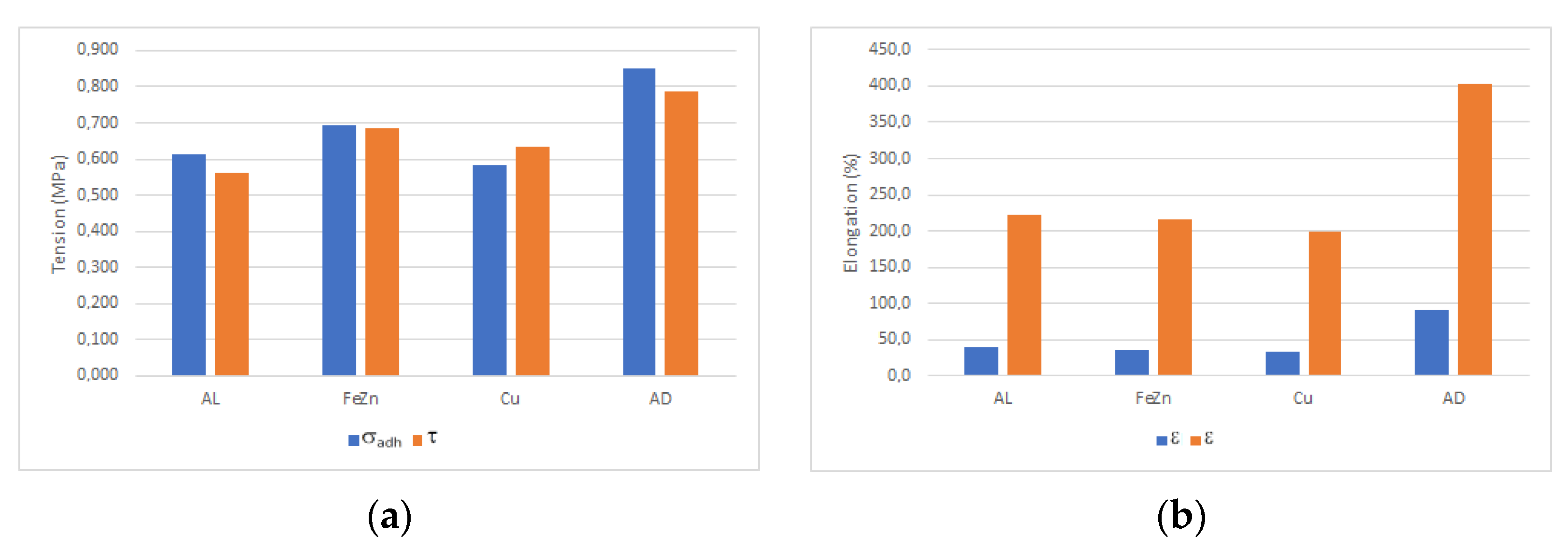
Figure 1. Test specimen for tensile test.
Materproc 13 00036 g001
Figure 2. Test specimen for shear test.
Materproc 13 00036 g002
Figure 3. Example of tensile test results for measuring adhesive deformation on aluminium targets.
Materproc 13 00036 g003
Figure 4. Example of shear test results for measuring adhesive deformation on galvanised strips.
Materproc 13 00036 g004
Figure 5. Comparison of test results: (a) σadh (in MPa) for tensile test (blue) and τ (in MPa) for shear test (orange); (b) ε (in %) for tensile test (blue) and shear test (orange).
Materproc 13 00036 g005
Figure 6. Possible types of destruction: (a) tearing of the metal strip including the adhesive from the plaster surface; (b) tearing of the plaster including the covering layer of the screed from the layer of reinforcing fibreglass fabric; (c) peeling off the adhesive from the copper strip.
Materproc 13 00036 g006
Table 1. Results of tensile adhesion σadh (in MPa) and elongation ε (in %), standard deviation sx (in MPa for σadh, in % for ε) and coefficient of variation vx (in %) 1 for aluminium alloy (Al), galvanised steel (FeZn) and copper alloy (Cu) targets compared to results of adhesive alone (AD) on aluminium targets.
AlFeZnCuAD
σadh0.6140.6940.5850.849
sx0.0560.1380.0740.035
vx9.219.812.74.1
ε39.835.533.390.1
sx11.18.310.410.2
vx27.823.431.311.3
1 The average values are a sum of six measurements conducted for each tested combination.
Table 2. Results of shear adhesion τ (in MPa) and elongation ε (in %), standard deviation sx (in MPa for τ, in % for ε) and coefficient of variation vx (in %) 1 for aluminium alloy (Al), galvanised steel (FeZn) and copper alloy (Cu) targets compared with the results of adhesive alone (AD) on aluminium strips.
AlFeZnCuAD
τ0.5620.6840.6340.786
sx0.0750.0440.0540.080
vx13.36.58.510.2
ε223.3217.0200.0403.3
sx18.622.124.269.2
vx8.310.212.117.2
1 The average values are a sum of six measurements conducted for each tested combination.
Disclaimer/Publisher’s Note: The statements, opinions and data contained in all publications are solely those of the individual author(s) and contributor(s) and not of MDPI and/or the editor(s). MDPI and/or the editor(s) disclaim responsibility for any injury to people or property resulting from any ideas, methods, instructions or products referred to in the content.

