
Design of a DC to DC Converter for a Residential Grid Connected Solar Energy System †


Wolfson Centre for Magnetics, School of Engineering, Cardiff University, Cardiff CF24 3AA, UK
*
Author to whom correspondence should be addressed.
†
Presented at the 1st International Electronic Conference on Processes: Processes System Innovation, 17–31 May 2022; Available online: https://ecp2022.sciforum.net .
Eng. Proc. 2022, 19(1), 6; https://doi.org/10.3390/ECP2022-12620
Published: 17 May 2022
(This article belongs to the Proceedings of The 1st International Electronic Conference on Processes: Processes System Innovation)
Abstract
:This article presents an investigation of a PV solar system based on Maximum Power Point Tracking (MPPT) using one of the artificial intelligence control techniques. To avoid the problems of the traditional P&O method, the optimization tool of Particle Swarm Optimization (PSO) is proposed to be employed with a Perturbation & Observation (P&O) technique with added a Proportional Integral (PI) controller (PSO + PI + P&O). This proposed method achieved the optimal operating variables of a photovoltaic (PV) module in terms to mitigating the issue of partial shading weather conditions. A DC–DC boost converter is designed to be switched to obtain the desired MPP based on the corresponding duty cycle according to the parameters provided by the IV characteristics. It is observed from the results that the proposed PSO + PI + P&O showed excellent improvement. Moreover, better performance was achieved in terms of extracting the maximum unique power point between both variables of current and voltage generated from the PV. The proposed MPPT control method was implemented in MATLAB/Simulink. The testbed of the suggested method was thorough and highlighted its high efficiency compared to the conventional P&O as well as the PI controller based on P&O methods.
1. Introduction
Partial shading due to weather conditions is still the main challenge in generating a power supply with high efficiency from a PV system. This phenomenon causes a drop in power energy from the PV system during its operation. In the last decades, oversizing of PV arrays was a solution to provide a sufficient power supply for the consumer. Nevertheless, the cost of solar panels is much increased. To mitigate this problem, a technique called MPPT was innovated to predict the maximum point of the power. The work performance of this technology was achieved to extract the Maximum Power Point (MPP) up to 97% of the designed PV system [1]. The duty cycle of a DC–DC boost converter can be considerably affected by the variant of MPPT. Several researchers have introduced some MPPT algorithms to tackle the main MPPT issues in regards to the shading conditions, and improve the efficiency of a PV system taking account of the non-linear power generation behavior between IV characteristics [2]. Reference [3] clarifies that the traditional MPPT method is based on the P&O algorithm which continuously researches to find the best values of voltage and current of a PV panel until the reliable value of MPP is reached. The drawback of this classical method was its inability to maintain the maximum power point under shadowing weather conditions. This increases oscillation and power outage of the assumed PV system [4,5]. PI controller was proposed by [6,7] to overcome the issues of the classical P&O technique, whereby the feedback error of IV characteristic was controlled by using a PI controller instead of the perturbation step size of the P&O method. The results showed the suggested PI control could achieve a fast extraction of MPP and reduce the oscillation of the rated power compared to the conventional P&O method. Although the drawback of the P&O algorithm was eliminated, the extended PI controller is likely to be substantially more difficult to tune the parameters based on trial and error technique. In such a case, the MPP of a PV system is not guaranteed to successfully overcome the perturbations of the shading condition. To face this issue, various optimization tools were employed in a PV system to interconnect with the control loop so as to obtain a PI controller design with optimal parameters. PSO has been used intensively as an optimization tool for a wide range of applications due to its features of simple structure, high reliability, easy implementation, and because it has got the merit that only small parameters can be adjusted. Several studies [8,9] concluded that the PSO technique has given a better result in terms of extracting the MPPT compared with P&O.
This paper proposes a PSO optimization algorithm based on the MPPT technique. The proposed method was investigated and compared to other MPPT methods by using MATLAB/Simulink. The results were analyzed and compared with the classical MPPT techniques. The suggested method provides an optimum value of extracted maximum power throughout the range of the data given.
2. System Design
The photovoltaic system is composed of four stages as described in Figure 1. The first part represents the energy source based on PV arrays, the second component is a boost converter, the third assembly acts as the load of the proposed system, and the Section 4 is the control scheme according to the development of MPPT.
2.1. PV Design
The sizing of PV modules is the intial design step to provide a desired value of the rated power based on IV characteristics according to the assumed load. The variables of the PV modules, Ipv and Vpv, are connected to a DC control loop called MPPT. Its purpose is to track and extract the unique point of the largest power generating region from the PV panels [10,11]. Moreover, the fill factor is an essential measure component to determine the efficiency of a PV module based on the constructed material of the module [12] and is obtained from Equation (1):
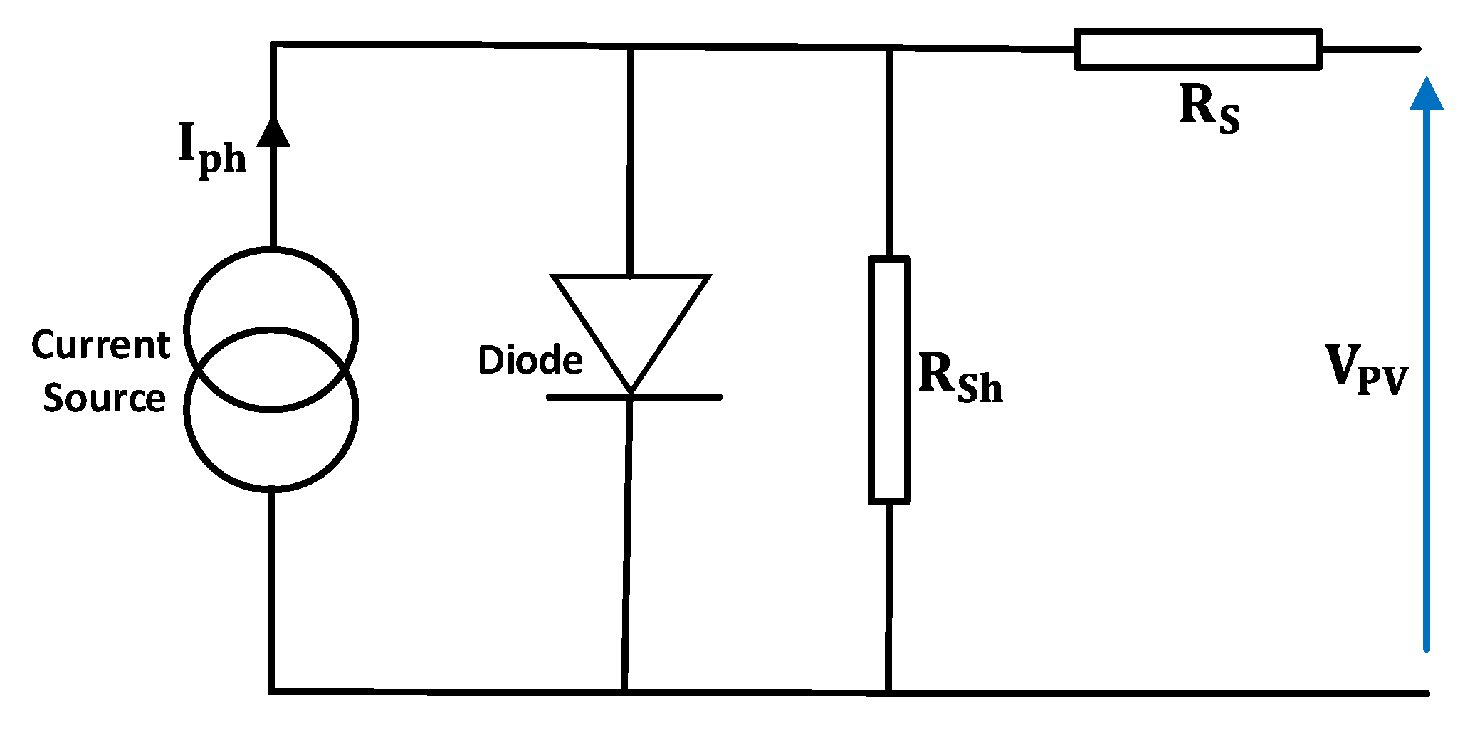
This static performance can be found from the following mathematical Equation (2), itself derived from fundamental electrical theory (Kirchhoff’s current law) illustrated in Figure 2.
The corresponding parameters of the above equation are described as follows: is the photo current; is the current short circuit; is series resistance; is the Boltzmann’s constant (1.381 × 10⁻²³ J/K); shunt resistance temperature in Kelvin (K); is Voltage of open circuit; and is irradiance in
SHARP PV module (ND-Q250F7) with 60 cells in series was selected as the power supply of the PV system. Table 1 illustrates the electrical specification of the PV given by the manufacturer.
2.2. MPPT Algorithms
The P&O algorithm has been widely used as a MPPT technique in many aspects of PV applications. It has the benefit of being constructed simply and implemented easily. The fundamental basis of the P&O method is to create repeatable process to obtain the optimum values of current and voltage to extract precisely the position of MPP [13]. PI controller is employed in the outer loop of the P&O algorithm to reduce the feedback error caused by the variation step size of the classical P&O. As a result, the extraction of the MPP becomes faster with lower oscillation of the output rated power [14].
PSO is an excellent candidate for application to MPPT technique because it is an effective and simple meta-heuristic approach that can be used in a multivariable optimization function. This is due to it’s having many local optimal points, which is a key merit of this technique [8].
2.3. Design of the Boost Converter
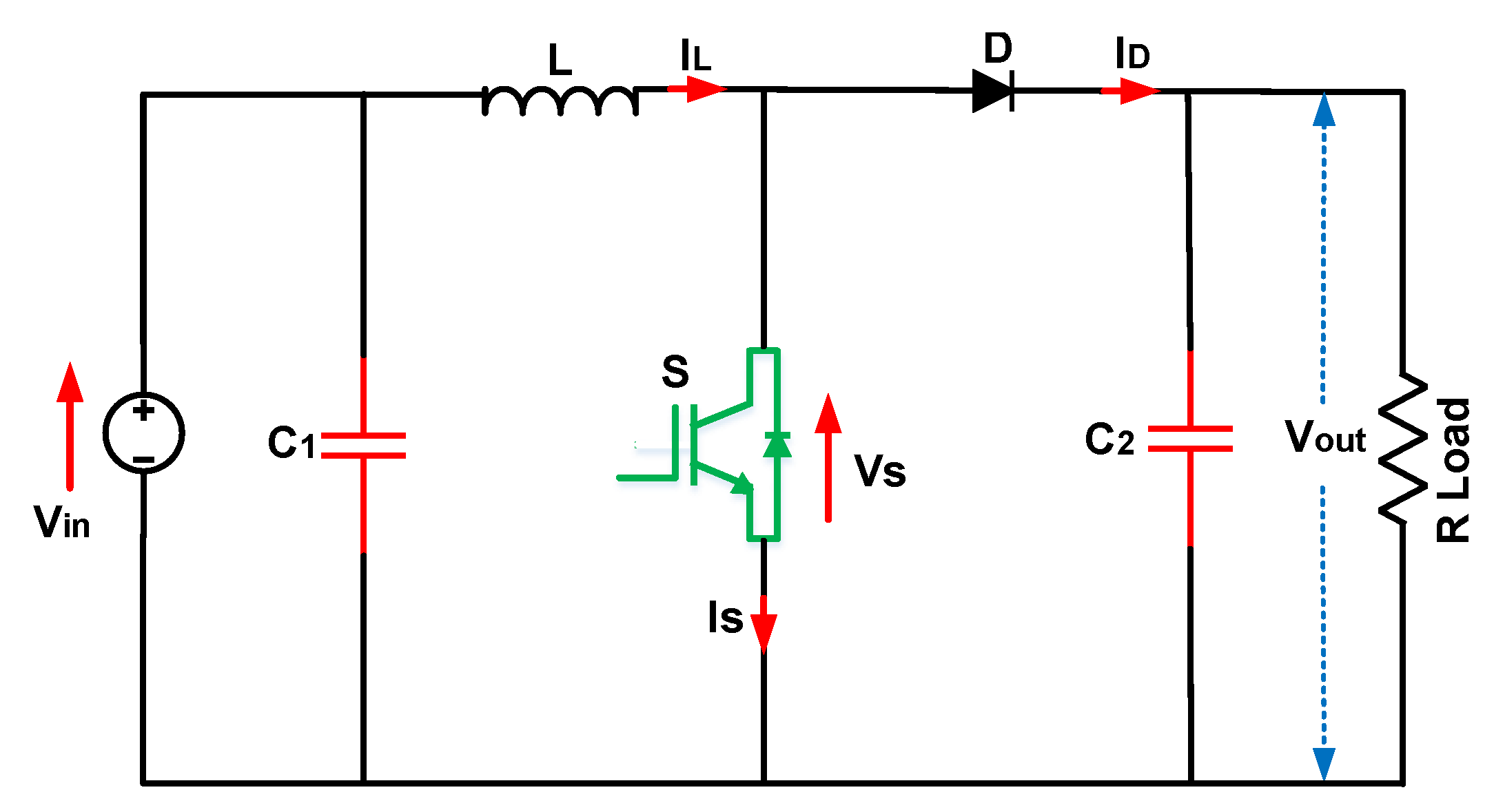
A DC boost converter is commonly utilized between the load and the power supply. It acts as a conversion step-up voltage stage based on a ratio of the duty cycle given via the MPPT control method. It is worth mentioning that the duty cycle must be calculated to be a certain amount to keep the output voltage level at the desired value. To do so, it makes an adaption between the suggested load and the rated PV panels to receive a duty cycle signal from a MPPT technique [15]. The basic methodology of the boost converter is to convert low input DC voltage to a much higher desired output DC voltage [16,17]. Figure 3 shows the boost converter composed of the inductor (L), the switch (S), the capacitor C2 designed to smooth the output voltage, and lastly, the diode which is used to protect S to avoid current feedback.
The following mathematical expression is to derive the output voltage [18].
Completion of the mathematical design can be derived by the following equations:
The input voltage of boost converter can defined by the following equation:
where: F is frequency, D is duty cycle and R is the load resistance.
Parameters of DC–DC boost converter are given in Table 2. The duty cycle of the boost converter is calculated according to the power rating demand of the householder.
3. Result and Discussion
This work was implemented in MATLAB (2020a). The proposed PV system was conducted by using three MPPT algorithms which are as follows.
- P&O algorithm.
- PI controller + P&O algorithm.
- PSO Algorithm + PI Controller + P&O algorithm.
The testbed considered two states of different irradiances G = 1000 and G = 800 with the constant temperature at T = 25 °C for the period given.
Figure 4 shows the dynamic performance of the proposed PSO based on MPPT with different algorithms to visualize the effectiveness of the suggested control algorithm. The proposed PSO optimization technique has demonstrated a high level of effectiveness and superiority with a much better achievement of power extraction compared to the other controls. By contrast, the P&O has large oscillations in the case of the shading conditions for all variables: power, voltage, and current.
4. Conclusions
The test was carried out under changed values of irradiance and fixed temperature. The proposed PSO control scheme provides satisfactory performance for many aspects such as achieving the highest extraction point of power and fast dynamic performance of the system. This was achieved despite a slight decrease in nominal rated power. This work can be extended in the future by implementing artificial intelligence such as a Genetic Algorithm (GA) to avoid much of the fluctuation around the MPP.
Author Contributions
Conceptualization, M.E. and F.A.; methodology, M.E.; software, M.E.; validation, M.E., F.A. and E.E.; formal analysis, M.E.; investigation, M.E.; resources, F.A.; data curation, M.E., F.A. and E.E.; writing—original draft preparation, M.E.; writing—review and editing, M.E., F.A. and E.E.; visualization, M.E.; supervision, F.A.; project administration, M.E.; funding acquisition, M.E. All authors have read and agreed to the published version of the manuscript.
Funding
This research received no external funding.
Institutional Review Board Statement
Not applicable.
Informed Consent Statement
Not applicable.
Data Availability Statement
Not applicable.
Conflicts of Interest
The authors declare no conflict of interest.
References
- Pakkiraiah, B.; Sukumar, G.D. Research Survey on Various MPPT Performance Issues to Improve the Solar PV System Efficiency. J. Sol. Energy 2016, 2016, 1–20. [Google Scholar] [CrossRef]
- Rajamand, S. A novel sliding mode control and modified PSO-modified P&O algorithms for peak power control of PV. ISA Trans. 2022; in press. [Google Scholar] [CrossRef]
- Verma, D.; Nema, S.; Shandilya, A.M.; Dash, S.K. Maximum power point tracking (MPPT) techniques: Recapitulation in solar photovoltaic systems. Renew. Sustain. Energy Rev. 2016, 54, 1018–1034. [Google Scholar] [CrossRef]
- Rezk, H.; Hasaneen, E.-S. A new MATLAB/Simulink model of triple-junction solar cell and MPPT based on artificial neural networks for photovoltaic energy systems. Ain Shams Eng. J. 2015, 6, 873–881. [Google Scholar] [CrossRef]
- Reisi, A.R.; Moradi, M.H.; Jamasb, S. Classification and comparison of maximum power point tracking techniques for photovoltaic system: A review. Renew. Sustain. Energy Rev. 2013, 19, 433–443. [Google Scholar] [CrossRef]
- Yusivar, F.; Tito, B. Solar Cell MPPT Technique Based on PI Controller. Adv. Mater. Res. 2012, 608, 89–96. [Google Scholar] [CrossRef]
- De Brito, M.A.G.; Galotto, L.; Sampaio, L.P.; Melo, G.D.A.E.; Canesin, C.A. Evaluation of the Main MPPT Techniques for Photovoltaic Applications. IEEE Trans. Ind. Electron. 2013, 60, 1156–1167. [Google Scholar] [CrossRef]
- Suryavanshi, R.; Joshi, D.R.; Jangamshetti, S.H. PSO and P&O based MPPT technique for SPV panel under varying atmospheric conditions. In Proceedings of the 2012 International Conference on Power, Signals, Controls and Computation, Kerala, India, 3–6 January 2012; pp. 1–6. [Google Scholar] [CrossRef]
- Ishaque, K.; Salam, Z. A Deterministic Particle Swarm Optimization Maximum Power Point Tracker for Photovoltaic System under Partial Shading Condition. IEEE Trans. Ind. Electron. 2012, 60, 3195–3206. [Google Scholar] [CrossRef]
- Bouksaim, M.; Krami, N.; Acci, Y.; Srifi, M.N.; Hadjouja, A. Modeling of photovoltaic module using maximum power point tracking controller. In Proceedings of the 2018 International Symposium on Advanced Electrical and Communication Technologies (ISAECT), Kenitra, Morocco, 21–23 November 2018; pp. 1–4. [Google Scholar]
- al Tarabsheh, A.; Akmal, M.; Ghazal, M. Series connected photovoltaic cells—Modelling and analysis. Sustainability 2017, 9, 371. [Google Scholar] [CrossRef]
- Qu, H.; Li, X. Temperature dependency of the fill factor in PV modules between 6 and 40 °C. J. Mech. Sci. Technol. 2019, 33, 1981–1986. [Google Scholar] [CrossRef]
- Putri, R.I.; Wibowo, S.; Rifa’I, M. Maximum Power Point Tracking for Photovoltaic Using Incremental Conductance Method. Energy Procedia 2015, 68, 22–30. [Google Scholar] [CrossRef]
- Anto, E.K.; Asumadu, J.A.; Okyere, P.Y. PID control for improving P amp; O-MPPT performance of a grid-connected solar PV system with Ziegler-Nichols tuning method. In Proceedings of the 2016 IEEE 11th Conference on Industrial Electronics and Applications (ICIEA), Hefei, China, 5–7 June 2016; pp. 1847–1852. [Google Scholar] [CrossRef]
- Sahu, P.; Verma, D.; Nema, S. Physical design and modelling of boost converter for maximum power point tracking in solar PV systems. In Proceedings of the 2016 International Conference on Electrical Power and Energy Systems (ICEPES), Bhopal, India, 14–16 December 2016; pp. 10–15. [Google Scholar]
- Purushothaman, S.; Sattianadan, D.; Vijayakumar, K. Novel compact design high gain DC–DC step up converter applicable for PV applications. Sustain. Energy Technol. Assess. 2022, 51, 101720. [Google Scholar] [CrossRef]
- Rashid, M.H. Power Electronics: Circuits, Devices, and Applications, 4th ed.; Pearson: Boston, MA, USA, 2014. [Google Scholar]
- Pradhan, A.; Panda, B. A Simplified Design and Modeling of Boost Converter for Photovoltaic Sytem. Int. J. Electr. Comput. Eng. 2018, 8, 141–149. [Google Scholar] [CrossRef]
Figure 1.
Scheme of a PV system.

Figure 2.
Equivalent Circuit of PV panel.

Figure 3.
Electrical circuit of the boost converter.

Figure 4.
Comparison results of power, voltage, and current using PSO + PI + P&O, PI + P&O and P&O.


Table 1.
Electrical Characteristics of Solar module SHARP ND-Q250F7.
| Electrical Characteristics | Variables |
|---|---|
| Maximum Power | 250 W |
| Number of cells | 60 |
| ) | 8.4 A |
| ) | 29.8 V |
| ) | 8.9 A |
| ) | 38.3 V |
Table 2.
Parameters of the boost converter.
| Electrical Variables | Values |
|---|---|
| Input voltage | 100–120 Vdc |
| Output voltage | 240 Vdc |
| Output current | 30 A |
| Switching frequency | 5 kHz |
Publisher’s Note: MDPI stays neutral with regard to jurisdictional claims in published maps and institutional affiliations. |
© 2022 by the authors. Licensee MDPI, Basel, Switzerland. This article is an open access article distributed under the terms and conditions of the Creative Commons Attribution (CC BY) license (https://creativecommons.org/licenses/by/4.0/).
Share and Cite
MDPI and ACS Style
Elgbaily, M.; Anayi, F.; Elgamli, E. Design of a DC to DC Converter for a Residential Grid Connected Solar Energy System. Eng. Proc. 2022, 19, 6. https://doi.org/10.3390/ECP2022-12620
AMA Style
Elgbaily M, Anayi F, Elgamli E. Design of a DC to DC Converter for a Residential Grid Connected Solar Energy System. Engineering Proceedings. 2022; 19(1):6. https://doi.org/10.3390/ECP2022-12620
Chicago/Turabian StyleElgbaily, Mohamed, Fatih Anayi, and Elmazeg Elgamli. 2022. "Design of a DC to DC Converter for a Residential Grid Connected Solar Energy System" Engineering Proceedings 19, no. 1: 6. https://doi.org/10.3390/ECP2022-12620