1. Introduction
The control of the interfaces has proved to be one of the crucial elements for the engineering of different types of optoelectronic devices such as OLED (organic light-emitting diodes), OSC (organic solar cells), and OFET (field effect transistor), which are based on organic and inorganic multilayer systems [
1,
2].
There are different strategies for the engineering of the interfaces, but certainly conjugated polyelectrolytes [
3] are playing an increasingly important role in organic [
4] and hybrid systems, including colloidal semiconductor nanocrystals [
5,
6] and perovskites [
7,
8].
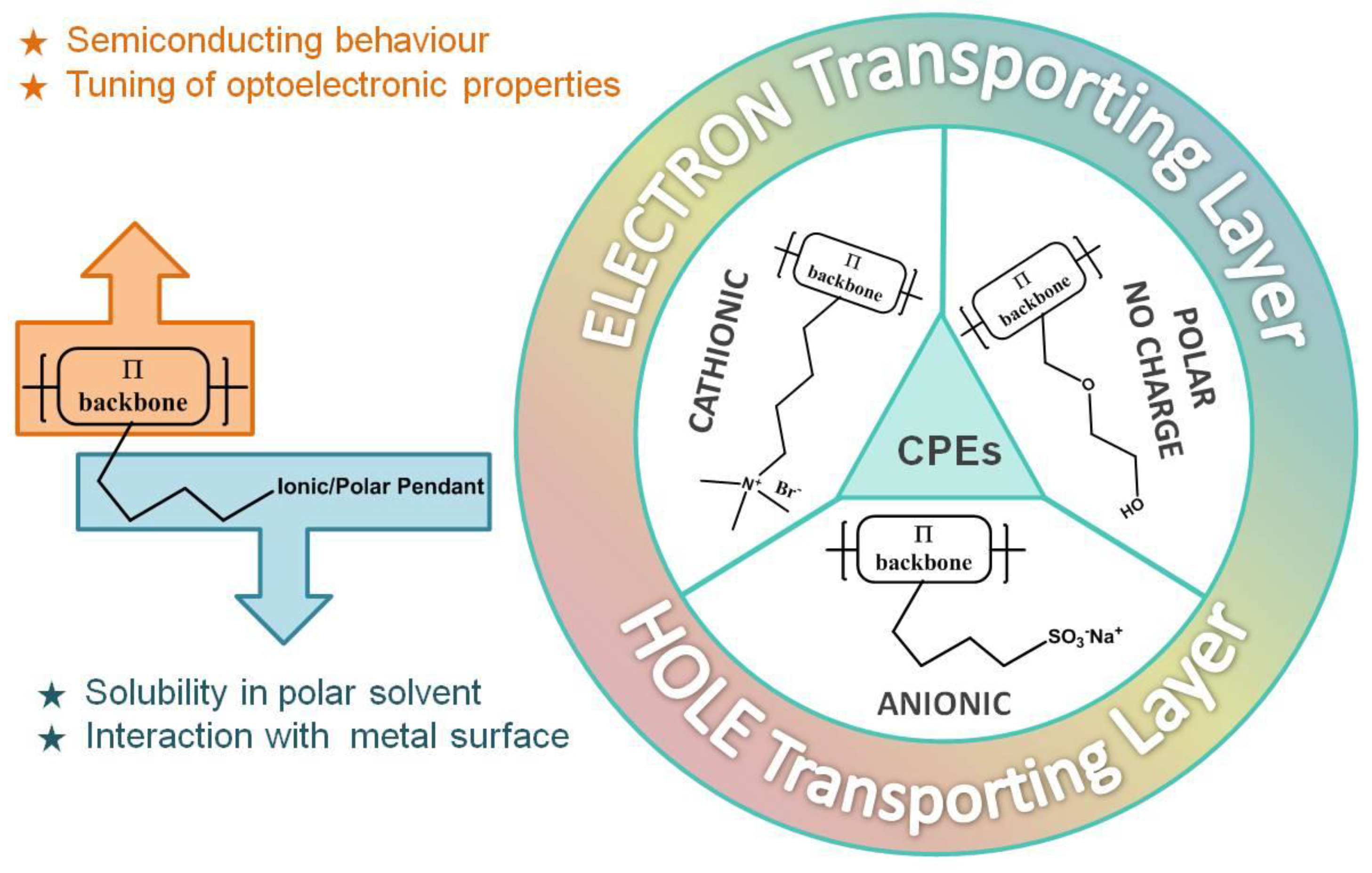
The conjugated polyelectrolytes are formed by an organic semiconductor backbone and by polar side pendants that can be anionic, cationic, or neutral.
Similarly, in traditional semiconductor polymers, it is possible to modify the main conjugated chain and consequently modulate the energy bandgap of the system. The presence of polar groups on the side chains, on the other hand, ensures solubility in polar solvents such as water.
The conjugated polyelectrolytes (CPEs) have proved to be particularly effective in solid-state optoelectronic applications. In fact, as solution-processed materials with respect to the evaporated counterpart, they are ideal for low-cost, large-scale technologies such as roll-to-roll or ink-jet printing; their orthogonal solubility simplifies the preparation procedures of the devices, preventing re-dissolution of the hydrophobic semiconducting layer during device fabrication; they are compatible with flexible devices; they are environmental friendly thanks to water solubility; they have unique solid-state interface properties, which increase the adhesion between organic and metallic layers; and they have the ability to reduce the barrier between electrode and active layers thanks to the formation of an aligned interfacial dipole at the metal/organic semiconductor interface.
There are mainly two kinds of interfacial materials that are commonly used in optoelectronic devices—if they are at the interface with the anode, they are called the anode interfacial layer, or AIL, and cathode interfacial layer, or CIL, when they are at the interface with the cathode (
Figure 1).
Considering a traditional direct geometry device, several CILs have been developed, which generally have a fluorenic, phenylene, or benzodithiazole-based backbone with cationic ammonium or polar substituent groups such as amine [
9,
10] or phosphonates [
11], while the development of AILs is lagging behind.
The most commonly used AIL material in OSCs is acidic poly(3,4-ethylenedioxythiophene):poly(styrenesulfonate) (PEDOT:PSS), thanks to its high optical transparency in the visible NIR (Near InfraRed) regime, suitable energy level, and sufficient conductivity. However its hygroscopic and acidic nature induces the etching of the indium from the indium tin oxide (ITO)/PEDOT:PSS interface, then causing the diffusion of indium and ultimately leading to fast deterioration of the devices [
12,
13].
Recently, Bazan and coworkers [
14] demonstrated an anionic low bandgap CPE copolymer based on the acceptor (A) benzodithiazole (BT) and on the donor (D) cyclopentadithiophene (CPDT) bearing sulfonated side groups. This copolymer can be easily doped after dialysis in water and, thanks to its pH-neutral nature, is a promising alternative to acidic PEDOT:PSS.
Although this material has been successfully incorporated in different types of devices [
5,
15,
16,
17], from a chemical point of view, it is important to understand the role of the backbone and of the lateral anionic substituents.
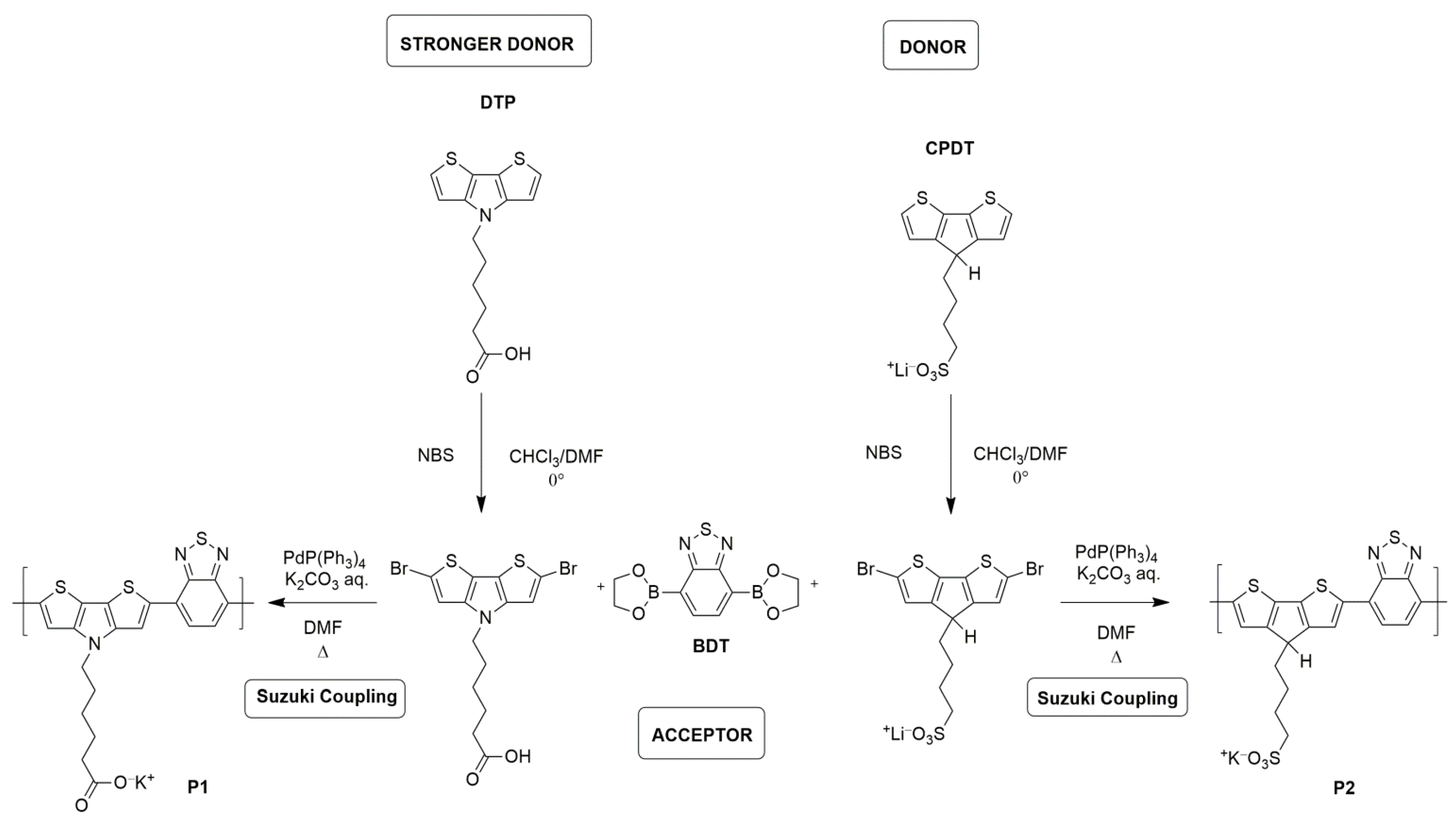
Herein, we present the synthesis and preliminary optoelectronic characterization of two new low bandgap D-A anionic CPEs as a possible anternative to PEDOT:PSS. We copolymerized the BT monomer with a dithienopyrrolo (DTP) unit that has been reported to be a stronger donor with respect to CPDT moiety. DTP has never been used, to our knowledge, in CPE, and for comparison, we synthetized a CPDT–BT polymer with only a lateral substituent. The DTP–BT polymer has a carboxylate lateral group with a lower acidity than the sulfonate group but with a stronger donor [
18] in the backbone (polymer P1,
Figure 2), and the CPDT–BT polymer is similar to the CPE proposed by Bazan et al., but bearing only one sulfonate group. We aimed to understand the combined role of the backbone, in particular the energy bandgap modulation, as well as the lateral polar groups in the self-doping process of these materials
The UV–VIS–NIR optical characterization combined with the electron paramagnetic resonance (EPR) showed that, regardless of the bandgap and the strength of the donors, the sulfonate group seemed to have a fundamental role in the self-doping process of the polymer.
Finally, P2 was also tested in a very preliminary OLED prototype.
2. Materials and Methods
All glassware was oven-dried. Unless specifically mentioned, all chemicals were commercially available and were used as received.
Ethyl 6-(4H-dithieno[3,2-b:2’3’-d]pyrrole-4-yl)hexanoate (
1) was synthesized following the procedure reported by Zecchin et al. [
19].
The dialysis membrane (MWCO: 3500–5000 Da) was purchased from Membrane Filtration Products Inc. NMR spectra were recorded at 600 MHz.
Dibromo-ethyl 6-(4H-dithieno[3,2-b:2’3’-d]pyrrole-4-yl)hexanoate (2). Compound 1 (150 mg, 0.511 mmol, 1 eq.) was suspended in dimethylformamide (DMF) (1 mL) and cooled down at 0 °C. A solution of N-bromosuccinimide (NBS; 182 mg2, 1.022 mmol, 2 eq.) in chloroform (CHCl3, 5.11 mL) was added dropwise under stirring. The reaction was allowed to reach room temperature in the dark by shielding the flask with aluminum foil. After 1 h at room temperature, the crude product was diluted with CHCl3 and washed 3 times with water. The organic solvent was removed under reduced pressure and the product was used without further purification. 1H NMR (D2O) δ: 7.00 (s, 2H), 4.05 (t, 2H), 2.30 (m, 2H), 1.85 (m, 2H), 1.65 (m, 2H), 1.35 (m, 2H).
Polymer P1. A mixture of compound 2 (230.5 mg, 0.511 mol, 1 eq.), 2,1,3-benzothiadiazole-4,7-bis(boronic acid pinacol ester) (198.32 mg, 0.511 mmol, 1 eq.), and tetrakis(triphenylphosphine)palladium(0) (Pd(PPh3)4, 11.8 mg, 2% mol) was added in a pre-degassed Schlenk flask, followed by 3 vacuum/nitrogen cycles. Then, degassed DMF (4.8 mL) and degassed potassium carbonate aqueous solution (1.2 mL) were added. The mixture was stirred at 110 °C for 3 h. The reaction mixture was then poured in acetone and the dark blue precipitate was collected by filtration and washed with copious amounts of acetone. The precipitate was all dissolved in deionized H2O and transferred into a dialysis tube (MWCO: 3500–5000). The dialysis tube was placed in a large beaker with H2O stirring for 3 days, and the H2O was changed every 12 h. Evaporation of H2O provided the title product as a dark blue solid (109 mg, 50%) after drying under vacuum overnight.
Synthesis of 4-potassium butanylsulfonate-4H-cyclopenta-[2,1-b;3,4-b’]-dithiophene (3). 4H-cyclopenta-[2,1-b;3,4-b’]-dithiophene (CPDT, 300 mg, 1.68 mmol, 1.0 equiv) and tetrabutylammonium bromide (27 mg, 0.084 mmol, 0.05 equiv) were dissolved in anhydrous DMSO (8.2 mL), and the solution was degassed by bubbling with Ar for 5 min. 50% KOH in H2O (1.8 g) was added via syringe, followed by the addition of 1,4-butanesultone (924 µL, 9.02 mmol, 1.2 equiv). After stirring at room temperature for 3 h, the reaction mixture was poured into acetone (50 mL), and the yellowish precipitate was collected by filtration and washed with acetone. The crude was used in the next step without further purification. 1H NMR (D2O) δ: 7.05 (d, 2H), 6.95 (d, 2H), 3.42 (t, 1H) 2.73 (t, 2H), 1.63 (m, broad, 2H), 1.56 (m, broad, 2H), 1.3 (m, broad, 2H).
Synthesis of 2,6-dibromo-4-potassium butanylsulfonate-4H-cyclopenta-[2,1-b;3,4-b’]-dithiophene (4). The crude product 3 was suspended in DMF (6.7 mL), and H2O (≈1 mL) was added while stirring until it was all dissolved. NBS (747 g, 4.2 mmol, 2.5 equiv) was added in the dark by shielding the flask with aluminum foil. The brown solution was stirred at room temperature for 1 h and poured into acetone. The yellowish precipitate was collected by filtration and washed with acetone (640 mg, 75% yield). 1H NMR (D2O) δ 7.23 (s, 2H), 3.74 (t, broad, 1H), 2.80 (m, broad, 2H), 2.60–2.50 (m, broad, 2H), 1.85–1.80 (m, broad, 2H), 1.55–1.45 (m, broad, 2H).
Synthesis of polymer P2. A mixture of compound 4 (117 mg, 0.230 mol, 1 eq.), 2,1,3-benzothiadiazole-4,7-bis(boronic acid pinacol ester) (89 mg, 0.230 mmol, 1 eq.), and Pd(PPh3)4 (5.2 mg, 2% mol) were added in a pre-degassed Schlenk flask, followed by 3 vacuum/nitrogen cycles. Then, degassed DMF (2.2 mL) and degassed potassium carbonate aqueous solution (0.55 mL) were added. The mixture was stirred at 110 °C for 3 h. The reaction mixture was then poured in acetone and the dark blue precipitate was collected by filtration and washed with copious amounts of acetone. The precipitate was all dissolved in deionized H2O and transferred into a dialysis tube (MWCO: 3500–5000). The dialysis tube was placed in a large beaker with H2O stirring for 3 days, and the H2O was changed every 12 h. Evaporation of H2O provided the title product as a dark blue solid (65 mg, 60%) after drying under vacuum overnight.
OLED fabrication and characterization. Glass substrates covered with indium tin oxide (ITO) pattern were washed ultrasonically in distilled water, acetone, and isopropyl alcohol. On the substrates, a water solution (2 mg/mL) of P2 was spincoated using 1400 rpm rotation, and subsequently the substrates were annealed at 100 °C for 10 minutes inside nitrogen-filled glovebox. Emissive layer was prepared from poly(9,9-dioctylfluorene-alt-benzothiadiazole) (F8BT, American Dye Source) dissolved in toluene at a concentration of 10 mg/mL and deposited with a rotation of 1000 rpm. Then, the devices were transferred to an evaporator where 7 nm of barium and 100 nm of aluminum were deposited through a shadow mask at 10−6 mbar pressure.
Electroluminescence (EL) spectra were recorded with liquid nitrogen-cooled charge-coupled device (CCD) combined with a monochromator (Spex 270M) and applying a constant bias. Keithley 2602 source meter was employed during current density–voltage–luminance measurements. Light emitted in forward direction from the devices was collected by a photodiode with known spectral response. In efficiency calculations, Lambert distribution was assumed. All characterization was performed in a nitrogen atmosphere.
3. Results and Discussion
Chemical characterization. The syntheses of compounds 1 and 2 are shown in
Figure 2 and confirmed by
1H NMR spectra (
Figure 3). In particular, the monosubstitution of monomer 2 was confirmed by the presence of a triplet at 3.74, attributable to H in 4 position in cylopenta-[2,1-b:3,4-b’]dithiophene [
20].
Polymer P1 and P2 were synthesized through Suzuki cross-coupling of a dibromide- of the donor unit and the bis-boronic ester of benzothiadiazole, with Pd(PPh3)4 as a catalyst and K2CO3 as a base in degassed DMF as solvent. The polymers were purified via dialysis membrane with a cutoff of 3500–5000 Da.
Differently from what was reported earlier [
15], where the pendant anionic moieties ensured CPEs solubility in polar organic solvents (e.g., ethanol) or water, both P1 and P2 polymers showed poor solubility both in traditional organic solvents and in polar solvents, probably due to the amphiphilic character given by the combination of the apolar backbone and the polar side chains.
The NMR spectra of the polymers showed only non-informative broad peaks, probably due to their paramagnetic characteristic, but the formation of the polymers was assured by the strong change of the color of the solution from colorless to blue/violet.
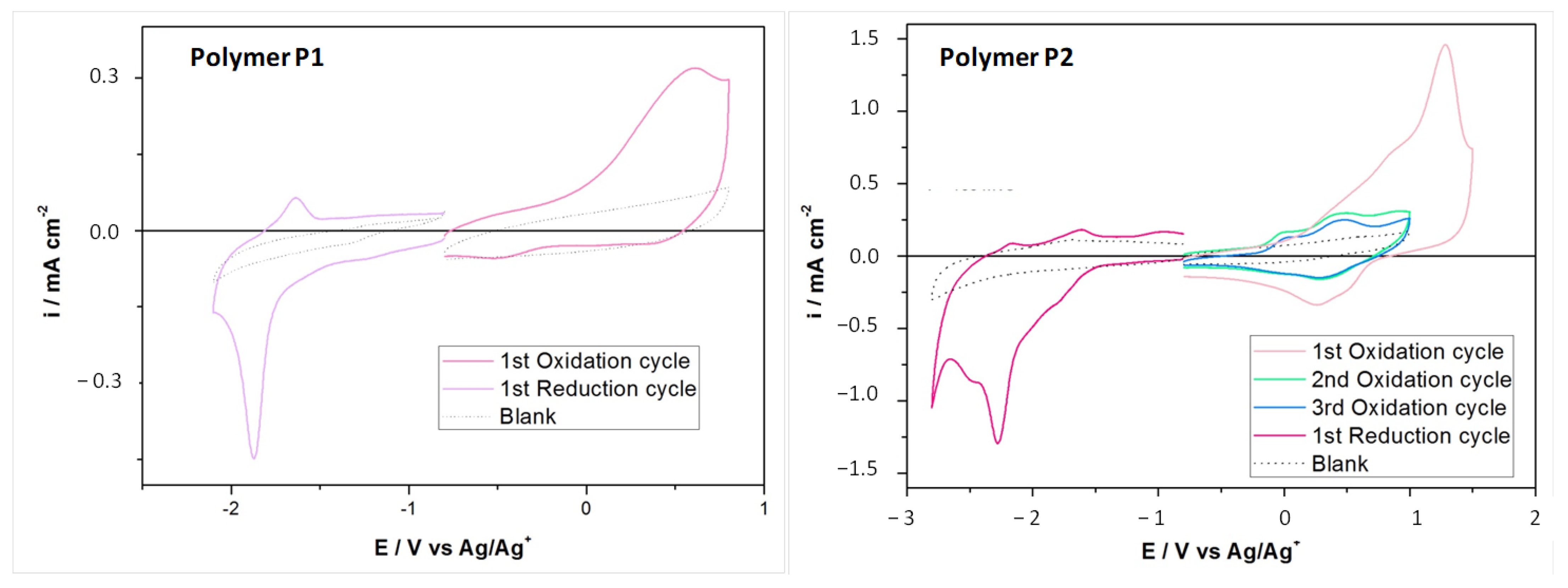
Cyclic voltammetry (
Figure 4) was applied to investigate the electrochemical properties. The HOMO levels of the polymer P1 and P2 (−4.8 and −4.92 eV, respectively) were in agreement with that reported by Bazan et al. [
14] for a similar polymer and were comparable to that of PEDOT:PSS (≈−5 eV) reported in the literature.
Polymer P2 showed an interesting behavior—the first oxidation peak was at high potential, while the second and third, perfectly reproducible, were at lower potential. Most probably this behavior indicated the formation of solid-state aggregates that disaggregate after the first potential application [
21].
Self-doping behavior. In order to understand the self-doping properties of the polymers, we recorded absorption spectra in water solution at different pH values. In fact, it has been shown for CPDT-based CPE that the acidic environment favors the doping of the polymers and that the formation of a polaron contributes in the absorption spectrum.
In UV–VIS–NIR absorption characterization (
Figure 5), the peak at 410 nm corresponded to p–p* absorption from localized p orbitals, while the higher intensity peak around 700 nm corresponded to the absorption from the intramolecular charge transfer (ICT) band [
14].
As can be observed in
Figure 5, the absorption spectrum of polymer P1 seemed to be unaffected by the addition of an acid or base to change the pH, pointing out that the polymer cannot be doped in acidic conditions. On the other hand, polymer P2 showed the uprising of a polaron band in the near-infrared region with the increasing of the acidity of the solution, confirming the self-doping behavior of the material [
14].
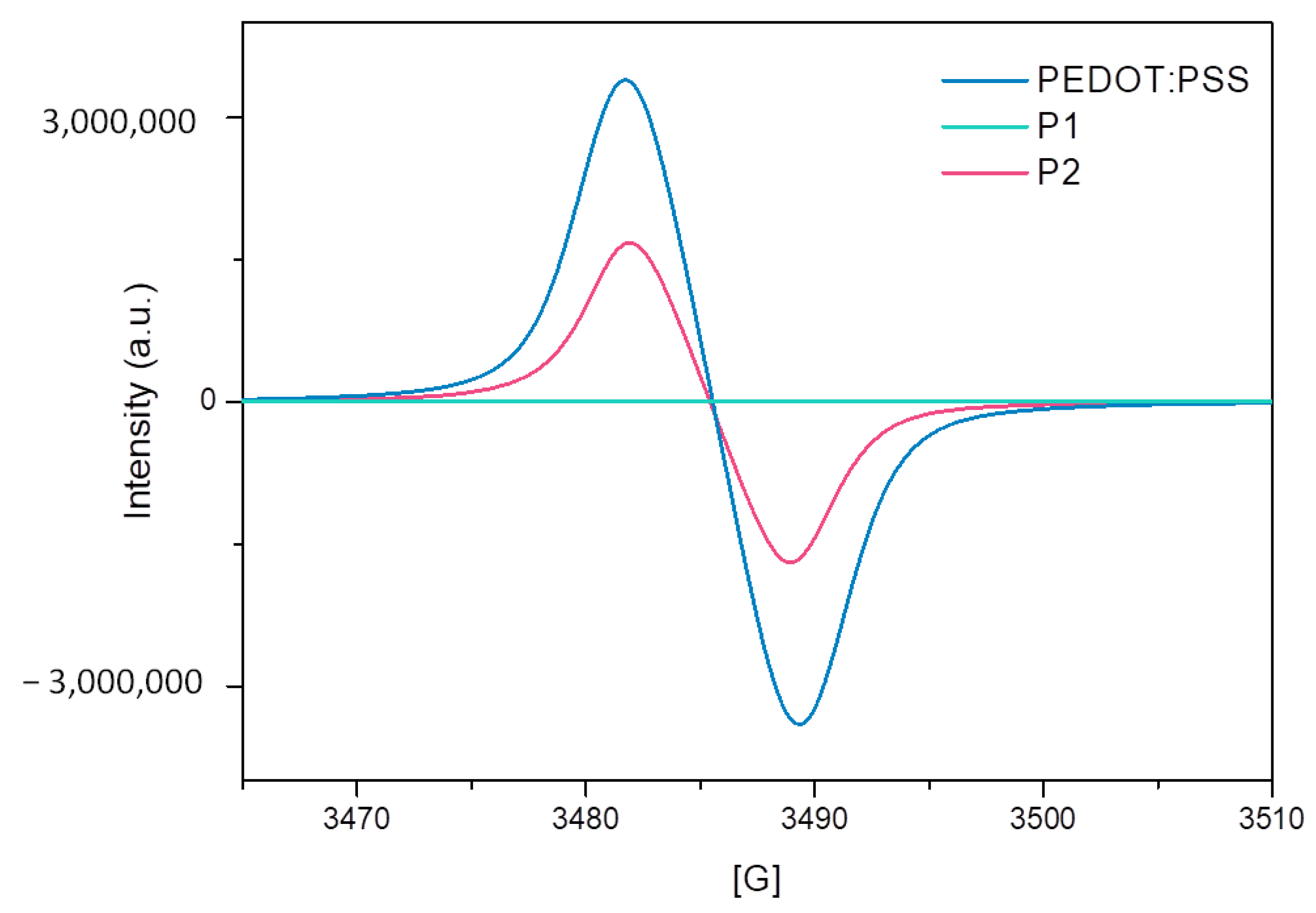
Further evidence of self-doping behavior was obtained by electron paramagnetic resonance (EPR) measurements in aqueous solution (
Figure 6)—strong EPR symmetric signal consistent with the presence of unpaired electrons was observed for both PEDOT:PSS and P2, while no signal was observed for polymer P1, in agreement with the absorption spectra.
Since both polymers had a low and very similar energy gap, the explanation of the different behavior was probably to be found in the different polar groups. The sulfonate group appeared to have a crucial impact in the formation of self-doped systems.
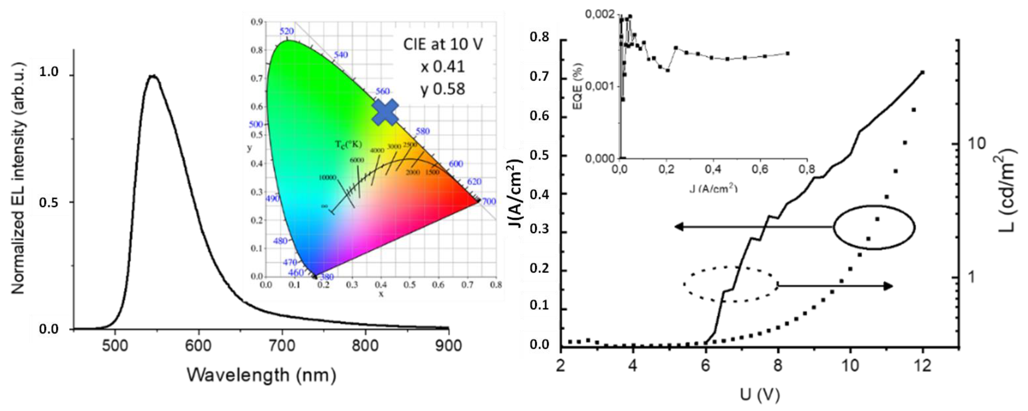
Preliminary OLED device. The polymer P2, showing self-doping behavior, was tested as a hole-transporting layer (HTL) in a PEDOT:PSS-free OLED architecture with F8BT as emitter. In the left part of
Figure 4, the EL spectrum of the diode is shown together with Commission Internationale de l’Eclairage (CIE) chromaticity coordinates (0.41, 0.58). The EL spectrum is typical for F8BT, and no contribution from P2 polymer was observed.
The performance of the device is presented in the right panel of
Figure 7. The J(U) and L(U) curves had forms typically observed for diodes. The device switched on at 6 V and the maximal recorded luminance approached 40 cd/m
2. Current density values were quite high and in combination with modest luminance led to a weak external quantum efficiency (EQE), shown in the inset of the right panel of
Figure 7. It should be underlined that performance was achieved for the device without any optimization.
4. Conclusions
Two new low bandgap-conjugated polyelectrolytes, polymer P1 and P2, were synthesized and characterized.
The DTP moiety, reported to be a stronger donor with respect to CPDT monomers, was used for the first time in the synthesis of a low bandgap CPE, giving a material with suitable HOMO–LUMO levels. Polymer P1 did not show a self-doping behavior, as confirmed by EPR measurements. On the contrary, polymer P2 seemed to be a promising material because it showed a self-doping behavior, hence highlighting the importance of the proper combination between low bandgap-conjugated backbone and suitable anionic substituent.
A very preliminary OLED device using polymer P2 as HTL was fabricated. The performance, even if modest due to the non-optimized architecture and parameters, showed the potential application of P2 compound.
This work will help guide the synthetic design of new, highly conductive CPEs. Specifically, we showed the importance of incorporating an electron-rich structural unit into the polymer backbone, which can be oxidized easily, as well as the necessity of having a pendant anionic group to stabilize the resulting positively charged backbone for self-doped polymer systems.
However, a more comprehensive understanding of the importance of sulfonate for the self-doping mechanism of CPE and its effect on charge transport and mobility is required to improve the design and the use of this class of polymers.


