1. Introduction
Maintenance of the DEMO breeding blanket includes the removal and replacement of plasma-facing components [
1]. To remove the breeding blanket, it must be disconnected from the piping system, which includes the coolant pipes and the tritium purge pipes [
2]. For this purpose, in DEMO, the concept that is being developed is the cut-and-weld connection, which uses a miniaturized laser optics package to apply the process around the entire pipe circumference [
3].
Mechanical Pipe Connections are being developed to connect and disconnect multiple cooling and purge pipes during blanket maintenance as an alternative to the cut-and-weld concept. As mechanical pipe connections have been used and standardized, whether in flange connection form [
4] or in clamped form [
5], all the mechanical pipe connections available are of single-pipe connection type. For deployment in DEMO, a manifold design with multiple pipes connected on the same flange is developed to reduce downtime and increase maintenance speed [
6].
This paper introduces the basic considerations, on which
Section 2 details the operating and boundary conditions, and on which the development of the mechanical pipe connection is built. From this basic consideration, the initial concept design is then drawn. From the concept design detailed in
Section 3, a structural analysis is conducted on the initial concept design, which is detailed in
Section 4. The result of the analysis is then used for an improvement of the basic design, which is then re-analyzed, as detailed in
Section 5 and
Section 6.
2. Basic Considerations
As a breeding blanket interface, a system design approach during identification of the requirements for the development of the MPC is followed [
7]. For the concept design, the operation conditions for all current blanket-cooling concepts have been captured. The aim of the MPC development is to try and provide a reasonable solution for all current cooling concepts. Only the requirements relevant to the development of the Mechanical Pipe Connections (MPC) are included in
Table 1.
The current development is focused on achieving a 10 mbar × L/s leakage rate for Helium as a blanket coolant. HCPB is currently considered the worst case from a sealing perspective, as He is most difficult to seal due to being in gas form and having small atomic size, as well as having a high operating temperature. Although WCLL has higher pressure, low leak rates with water are not as difficult to achieve as with Helium, and the temperature is lower. One may notice that DCLL PbLi has a higher temperature and the same pressure as HCLL; however, similar to WCLL, the leak rates should not pose the same challenge as Helium. This is chosen due to the severity of the conditions as seen in the table that confirms the working condition of the upper port of DEMO, which includes:
Ability to operate in ultra-high vacuum conditions.
Use of quick-release bayonet connection instead of a threaded connection to reduce the time required to engage and disengage the locking mechanism
Use of disc springs for preloading and locking shafts to apply and hold the sealing load on the flanges. This is to remove the possibility of a diffusion bonding of the locking mechanism that can happen with a threaded connection.
Double sealing around each pipe and an additional sealing over the flange circumference.
Use of a seal that can withstand a temperature requirement (up to 550 °C) and fulfil the allowed Helium leak rate of 10 mbar × L/s.
Only passive mechanical elements to meet the DEMO requirements.
Active components such as hydraulic tensioners and installation tools can only be deployed during the maintenance phase.
3. Concept Design
For use within the scope of DEMO, two concept designs are developed, as shown in
Figure 1. Concept design one relies on inside clamping of the two flanges, while concept design two applies the clamping force on the perimeter of the flanges. Mechanical pipe connections will also be used outside the upper and divertor port area of the DEMO tokamak, where mechanical connections will be also required. The designs have different space and access requirements, which makes both concepts suitable for different application areas in DEMO.
As with the requirement defined in
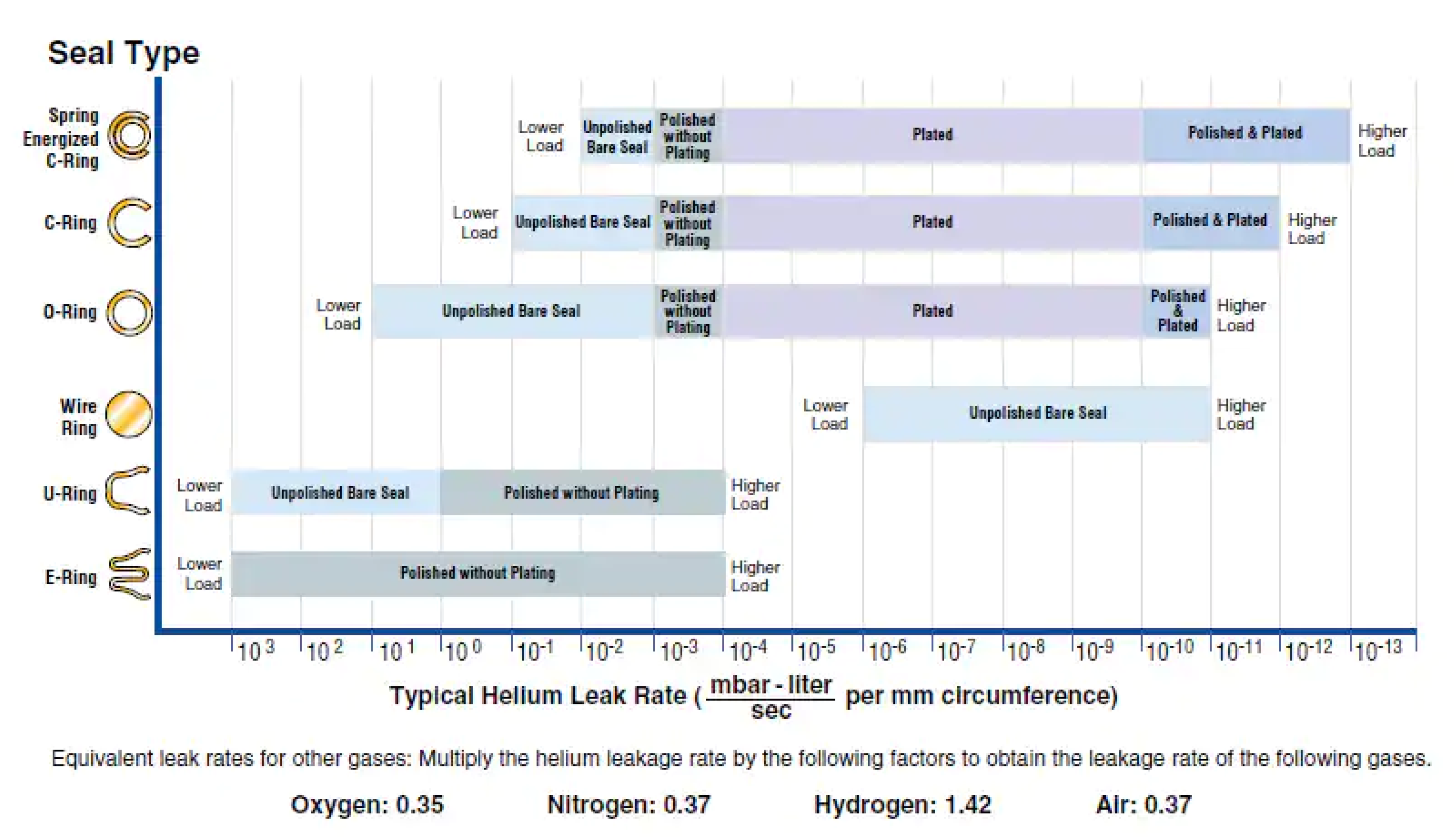
Section 2, the MPC will be using metal seals. In this case, a spring-energized metal seal is chosen due to its properties and its previous use in a nuclear setting such as in ITER and JET [
8] (Comparison between multiple seal types are seen in
Figure 2). To provide a seal between the pressurized interior and the vacuum exterior, the spring-cored metal seals needs a constant preload, where the amount of preload depends on the size of the seal. The advantage of using a spring-energized seal lies in its spring-back ability, which allows for small flange deformations under pressure or temperature spikes while still not exceeding the specified leak rate.
A closer look at the calculation of the total end force for the seal shows why the pipe diameter
has the highest impact on total end force. The inner force
, resulting from the operating pressure p, is equal to:
In addition, the sealing force
, which must be maintained at all times during operation:
while
is the sealing load usually given by the manufacturer, gives the end force:
The total end force
is then given after taking in account the loss of Young’s modulus for the material at 550 °C:
where
and
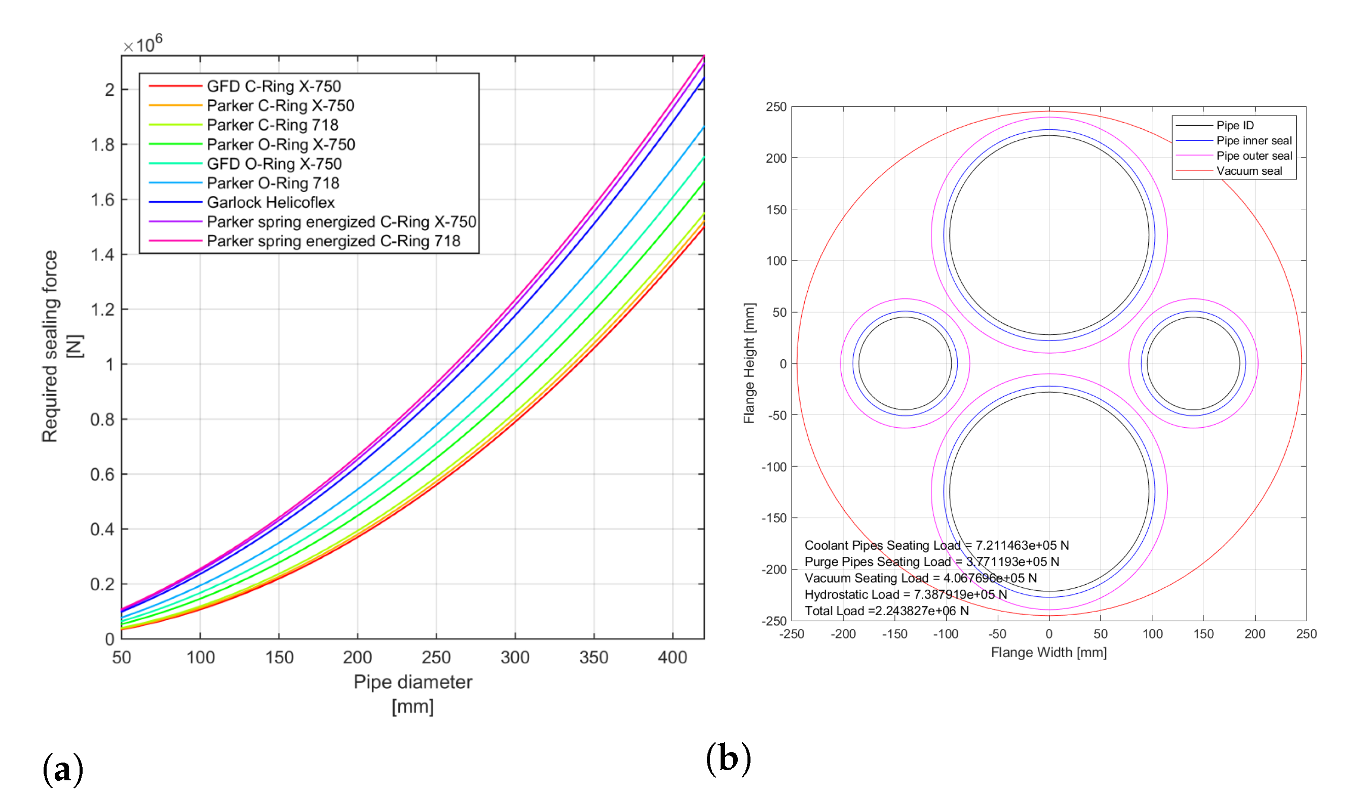
represents Young’s modulus of the used material at 20 °C and 550 °C. This calculation does not consider other thermal effects such as thermal expansion and the resulting increase in mechanical stress. All calculations made are preliminary and are meant to give an initial impression of the required forces for the RH tooling. The required sealing forces for sealing different pipe diameters. Several potentially suited seals on the market are shown in
Figure 3a.
The total required sealing forces, e.g., flange with double sealing, are shown in
Figure 3b. From that it can be concluded that the MPC will require over 2,000,000 N sealing load for DEMO operation conditions. This proves a tremendous challenge from a structural and RH perspective.
4. Structural Analysis
Both concepts offer a different set of advantages and drawbacks for the particular use in DEMO. Both advantages and drawbacks are described in
Table 2.
Both concepts are then analyzed using numerical methods (finite-element analysis) to determine the stress distribution of the component under load conditions. Both designs have been assessed on their structural capacity to handle sealing and operational loads. To avoid very long simulation runtimes, the disc springs have been replaced by reaction loads and boundary conditions at the associated contact surfaces. In the initial phase, the deformation behavior of the sealings were not included in the simulations. The material that is used for simulation properties of both concepts is EUROFER97. At room temperature, the maximal tensile strength of EUROFER97 is rated at 654 MPa and at 550 °C is rated 352 MPa [
10].
The main objective of this study is the analysis of the initial concept design to see if the concept design can structurally withstand the loads, which consists of four conditions. The study includes 3D finite-element analysis with the solid parts meshed with C3D8R (eight-node linear brick, reduced integration, hourglass control) to determine the mechanical stress and flange displacement for both designs with the following load cases:
Sealing load applied. The sealing load, which is calculated as the seal-sealing force multiplied by the total length of the metal vacuum seal. For this study, the value of the seal-sealing force is 260 N/mm, as given for the Helicoflex metal seal [
8].
Sealing load and design hydrostatic pressure of 9.6 MPa applied
All first seals failed (interspace between the first and the second seal is now also under pressure).
Complete sealing failure (interspace between the first and the second seal, and the second seal and the vacuum seal is now also under pressure).
Due to the difference in the outer circumference and therefore the length of the vacuum seal, the hub-and-clamp concept will have an applied sealing load of 2700 kN and the compact-flange concept will have an applied sealing load of 3300 kN.
A design that is mechanically stable with all first seals failed should be able to withstand a single-seal failure. Apart from the mechanical stress, flange bending under operation pressure and sealing failure was investigated as well because metal seals can withstand a limited amount of deformation before a leak occurs.
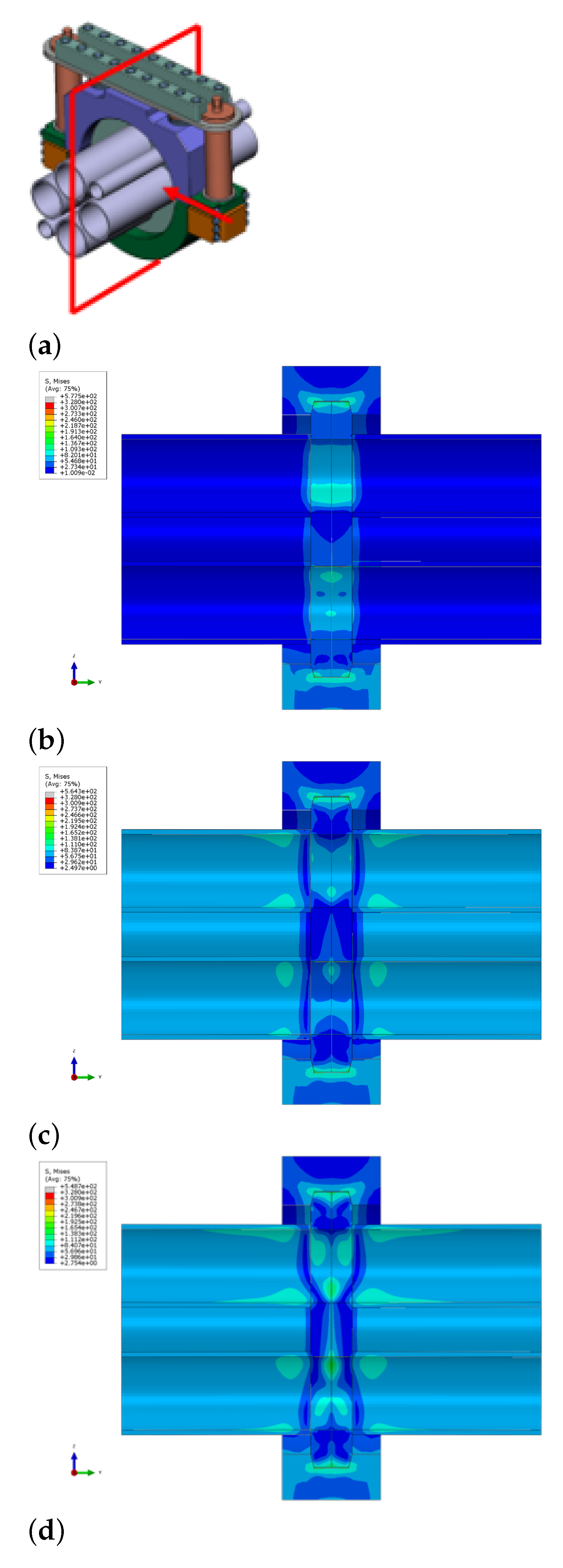
The hub-and-clamp concept, as shown in
Figure 4, shows that the design is feasible, and the clamping mechanism can withstand the operation pressure and all first-seal failure. The flange-bending behavior must be optimized to meet the leak-rate requirements.
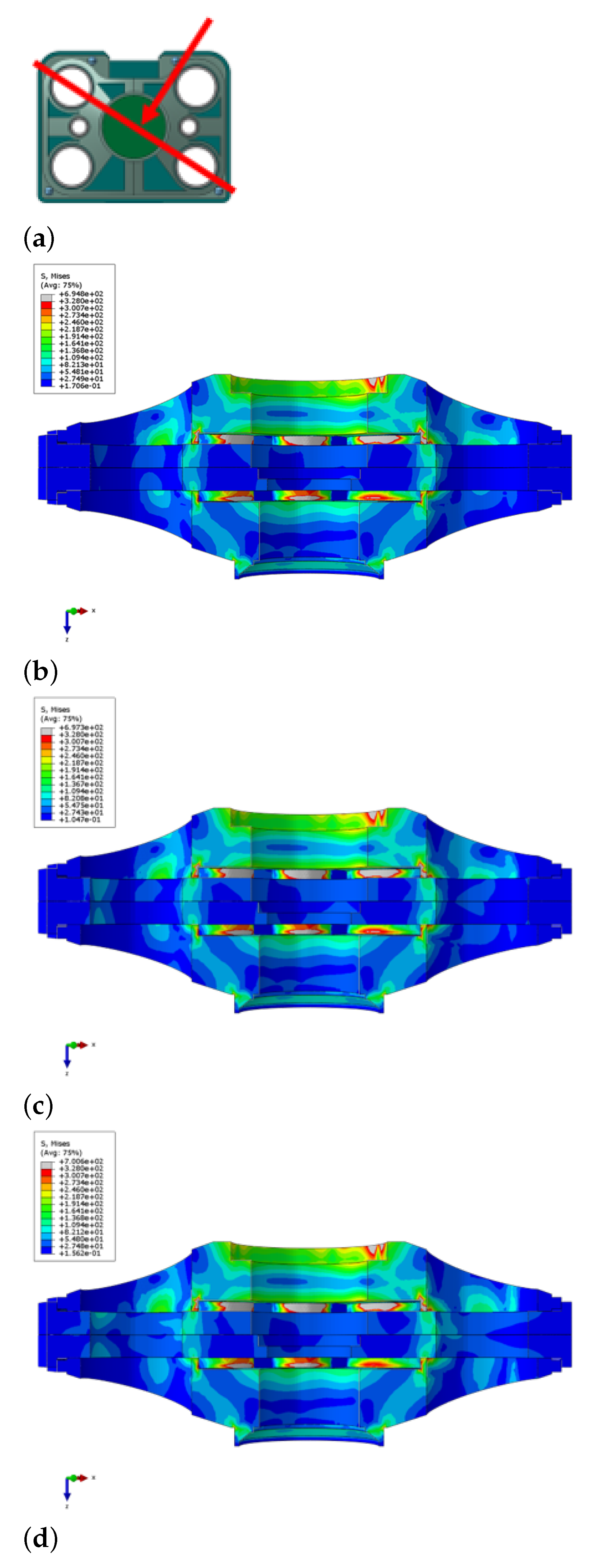
On the other hand, the FEA simulations for the compact-flange concept, as shown in
Figure 5, show that the design does not meet the requirements. Redesign work is required and is ongoing. Flange bending has not been investigated, as the design fails under the sealing load.
With this result, it is then decided for the first iteration and eventual proof-of-principle (PoP) testing that the hub-and-clamp design will be used due being inherently more robust. The PoP testing is conducted with this configuration to test the behavior of the seals with minimal effect from the structural form of MPC itself, such as the MPC unit breaking under stress before the seals shows any sign of leak. Despite showing failure in the initial finite-element testing, with further development a compact-flange concept can be made as robust as the hub-and-clamp design while occupying less space. The compact-flange concept will be developed in the future if such need for a more space-efficient pipe connection arises.
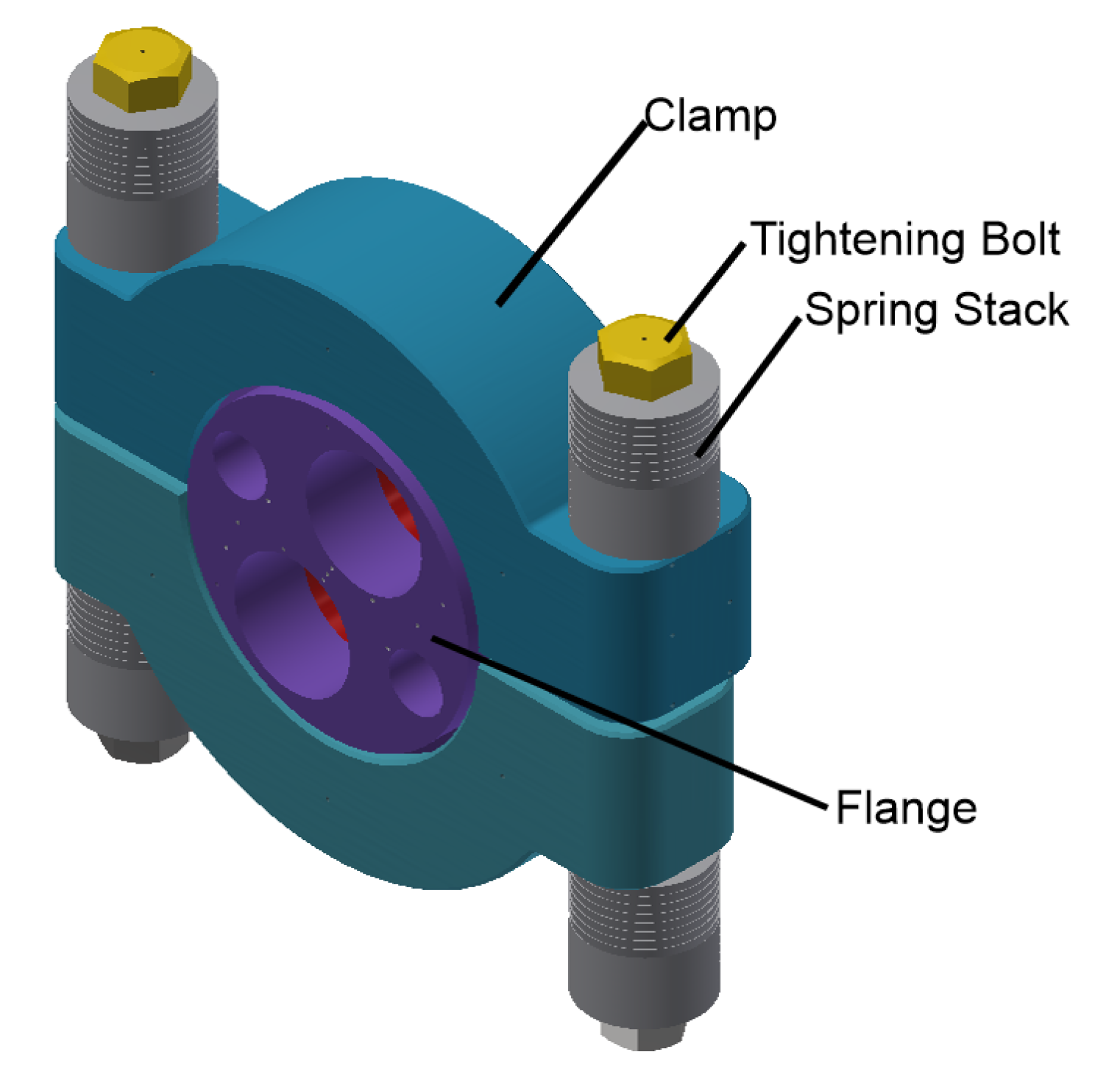
5. Improvement
From the earlier finite-element analysis, the clamp and hub concept is taken further due to the more robust nature of the design. With minimal modification, this concept can be made to fit the DEMO requirement. Main modifications which are made to improve the hub-and-clamp design are as follows:
Increase in the flange diameter, thickness, and clamp size;
Increase in the distance between each pipe;
Positioning of the spring stacks in the same axis with the fastening bolt;
Introduction of a concave flanged surface on one flange side
The resulting design from the first iteration of improvement is shown in
Figure 6.
The amount of cooling pipes per flange has been reduced from two pairs (four pipes) to one pair (two pipes); this reduction is made due to the overall change to the HCPB blanket design where there is one inlet pipe and one outlet pipe per breeding blanket segment [
11,
12].
The overall flange dimensions are increased to reduce overall mechanical stress in the flange, while increasing the distance between the pipes allows for a stiffer flange which will have less deflection under buckling conditions.
Designing a disc spring that can be stacked in a concentric configuration with the fastening bolt allows for a larger spring, which helps increase the available pretension force, allowing for more sealing force to be applied to the metal seals.
An angled contact patch, as shown in
Figure 7, is introduced to better improve the force distribution and reduce the pretension required on the tightening bolt to achieve the required seating load [
13]. An angle of 15° is chosen as a compromise between the amplification of the wedge effect and the required assembly force due to surface-to-surface friction between clamp and flange.
After a few iterations of the design, it is apparent that increasing the flange size has an effect of diminishing returns. After a certain dimension is reached (in this case a flange thickness of 115 mm), the extra thickness of the flange will not reduce the buckling affecting the flange. However, making the flange thicker will increase the size of the clamp as well, since the distance between the clamping surface of the two flanges will increase with an increase of flange thickness.
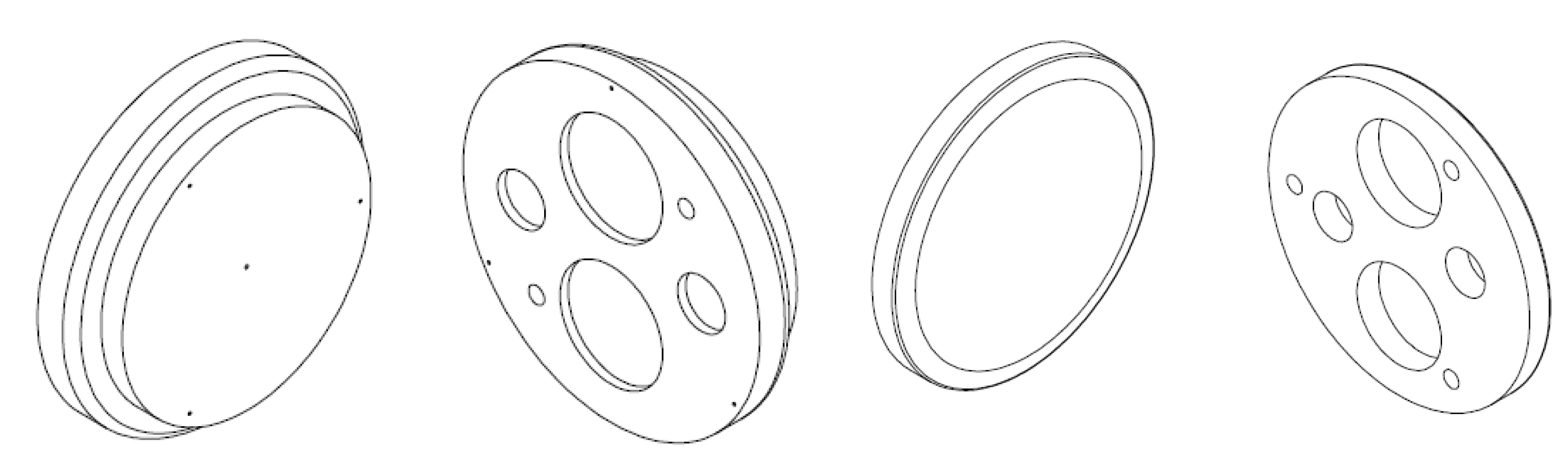
A workaround for this problem is to use a flange collar, as seen in
Figure 8. By keeping the flange clamping profile the same and adding more material to the center of the flange, some form of buckling mitigation can be achieved while keeping the clamping profile the same and thus making the increase of clamp size unnecessary.
To further alleviate the issue of seal leak due to buckling, a concave flange surface is used to ensure that contact between the seals and the flange surface is maintained under every condition.
6. Development of the Test Bench
From the improvement of the overall MPC design that is described in
Section 5, the concept is then taken to the next logical step, which is to construct a PoP test bench. The main purpose of the PoP test bench is to observe firsthand the behavior and characteristics of the MPC unit under controlled laboratory conditions.
For the PoP testing, the main observation goals consist of several points.
Behavior of metal seals in a high-pressure manifold connection under room-temperature and high-temperature conditions.
Interaction between multiple metal seals in a single-pipe connection.
Validation of the numerical model of MPC under room-temperature and high-temperature conditions.
Therefore, several simplifications have been taken into account for the development of the PoP unit (whether due to the streamlining of the experimental procedure, or due to the limitation of available technology). A list of the simplifications which were made are as follows:
A simplification is made due to the restriction of the test kiln used for the PoP testing. The kiln has dimensions of 1 , which makes the prototype unit with full size pipe unfeasible.
The spring preloading system with a bayonet closing mechanism must be abandoned due to significant safety uncertainty regarding the use of custom-sized disc springs under high-temperature conditions.
The bayonet system is replaced with a bolted connection to simplify the overall PoP test design.
Due to the lack of availability of EUROFER97, P91/1.4903 Stainless Steel is used as an analog due to the similar chemical composition and behavior at high temperature to EUROFER97, while also being available on the market. [
14]
Although there is no widely accepted and available code on the market that regulates the sizing and measuring of a multi-pipe MPC, single-pipe MPC has been established on the market with mechanical codes and standards that regulate the sizing of single-pipe MPC. One such code is the ASME code regarding pressure vessels, regulated in ASME BPV Code VIII-Div 1 [
15], specifically Appendix 24. Regarding this standard, there is a codified standard on how to size a single-pipe MPC to meet the required structural strength at assembly and operational conditions. With this in mind, a modification to the code was conducted to develop a preliminary sizing calculation for the multi-pipe MPC.
Using the ASME calculation code, equivalent stresses are calculated for nine types of stresses that a mechanical pipe connection would experience.
Transcribing the standardized code for single-pipe MPC directly one-to-one into multi-pipe MPC is not possible, due to the physical differences of both designs. However, some mathematical simplification and approximation can be used to approximate a multi-pipe joint into a single-pipe connection. The assumption that was made was to use an equivalent single-pipe ID and OD from the two coolant pipes (DN200) and two purge pipes (DN90) using the surface area.
This equation, however, will deliver an inflated value for the longitudinal stress (stress along a single-pipe axial direction) due to the stiffness difference between a single large pipe and multiple smaller pipes. The parameters that are used in the ASME code to ensure proper design are shown in
Table 3.
For a design with a 1.5 safety factor, the maximal stress value allowed during assembly conditions at room temperature and during operational conditions at 550 °C is shown in the right column of
Table 3.
According to the ASME code, the design of the test rig passed the required parameter except for hub longitudinal stress. This is, however, due to the nature of the ASME code, which was developed for single-pipe connections; therefore, the longitudinal stress (stress along a single-pipe axial direction) cannot be taken to be the same as it is for a multiple-pipe connection. Therefore, the stress on the pipe will be modeled in further development with FEA.
Another simplification that is considered is the length of the pipe. Due to space restriction, the nominal pipe length on which the MPC will be situated [
16,
17] will not fit inside the high-temperature kiln. Therefore, a study is conducted with FEA to investigate the correlation between pipe length and the deformation of the flanges due to hydrostatic forces.
As per
Figure 9, for the PoP MPC unit, there is no significant effect on the flange for a pipe longer than 400 mm, as the effect of pipe stiffness diminished significantly after a certain length. A further study is carried out if the short pipe stub of 400 mm can be replaced by a simple bore hole, which can also mimic the stiffness of the pipe.
This study yields that a blind hole with a depth of 30 mm can mimic the effect of a pipe longer than 400 mm, shown in
Figure 10. With this further simplification, a finite-element analysis is carried out to investigate the MPC stress and flange deflection during the operating condition.
A finite-element model of the MPC is built with all of the solid components meshed with C3D8R (an eight-node linear brick, reduced integration, hourglass control) as used in
Section 4, while the gasket model uses GK3D8N (an eight-node three-dimensional gasket element with thickness-direction behavior only) with the specification provided by Technetics as an analog to the Helicoflex metal seal [
8]. The loads applied on the MPC is divided per step of the simulation:
The MPC assembly step would be simulated by a displacement-driven bolt load of 14 mm to simulate the initial tightening before contact between the flanges and clamps
The displacement-driven bolt load is replaced with a tightening force of 750 kN per bolt. (1.5 MN in total); the bolt load is depicted in
Figure 11.
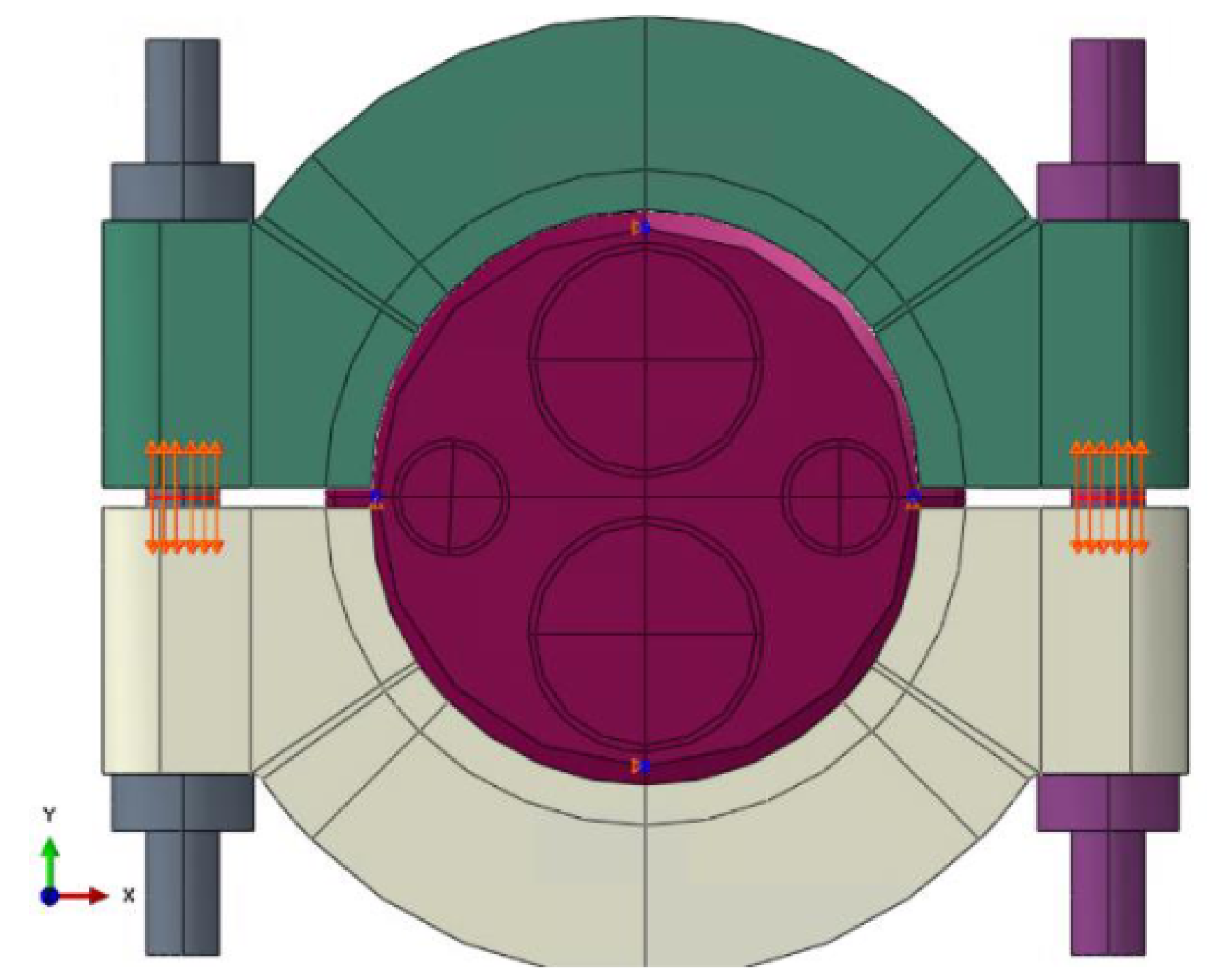
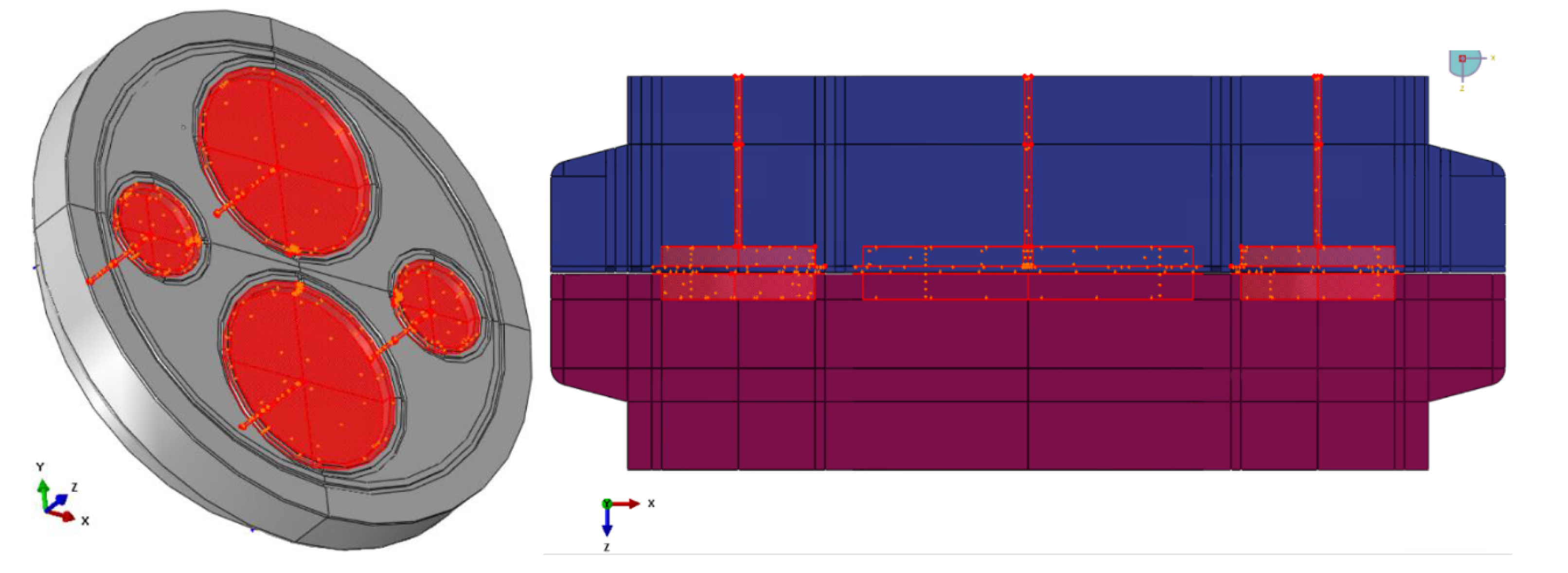
The surface of the pressure chamber is pressurized from an initial pressure of 0 MPa to 9.6 MPa. The surfaces on which the pressure load will be applied is shown in
Figure 12 and
Figure 13. This area is defined up to the inner seal mean diameter.
In the last step, all components in the assembly are gradually heated from a temperature of 20 °C (293.15 K) to 550 °C (823.15 K).
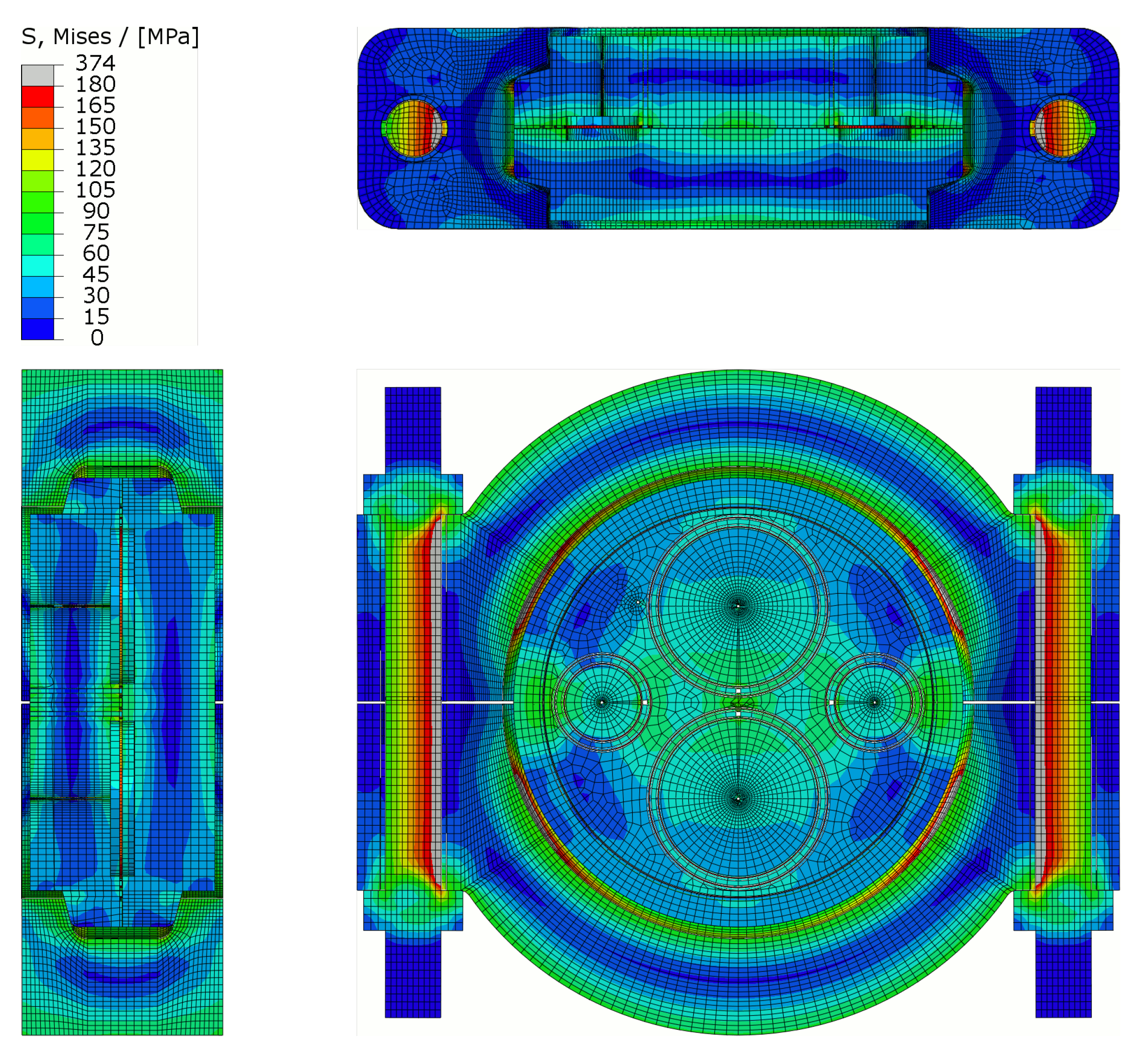
With the improved design, all the components comply with the safety factor of 1.5 to the rated P91 tensile strength at 550 °C (180 MPa) during the tightening procedure, pressurized condition and heating phase from room temperature to 550 °C, as shown in
Figure 14.
The only exception to this is the stress of the tightening bolts. However, the finite-element model of the bolts is not representative of the actual stress model of a bolt, which necessitate the use of another standard for the calculation of the bolt stress using CODAP standard section A6.2520, which is beyond the scope of this paper.
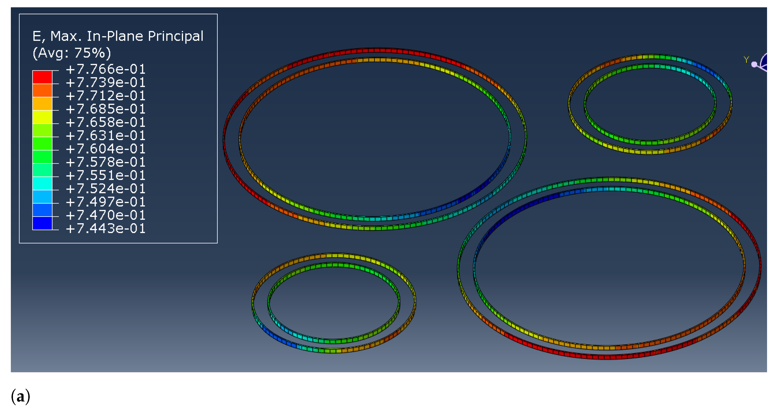
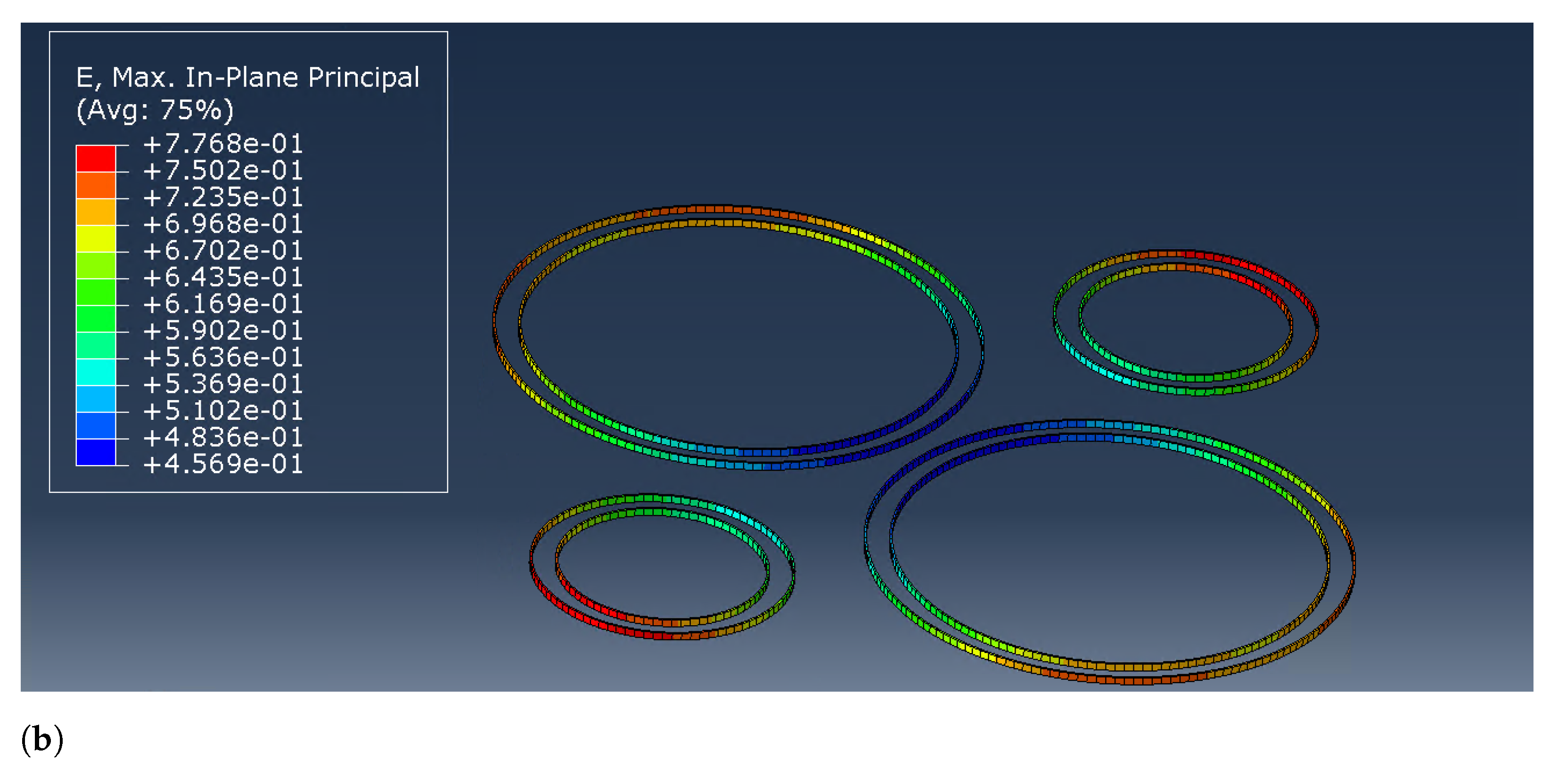
With the introduction of a thicker flange (from 75 mm to 115 mm) and a convex surface on one of the flanges, a more uniform distribution of force and deformation is achieved with the delta of seal deformation range reduced from 0.32 mm to 0.04 mm as shown in
Figure 15. This fulfils the sealing requirement for a maximum flange deflection of 0.1 mm.
7. Conclusions and Future Work
During the development of DEMO, MPC was developed as an alternative to the cut-and-weld concept for pipe connections as a mean to minimize downtime. The development of the mechanical connections converges on two main design concepts—the compact-flange concept and hub-and-clamp concept, as shown in
Section 3. Initial finite-element analysis shows that for use in HCPB configurations, the compact-flange concept suffers from high stress concentration, while stress is better distributed with the hub-and-clamp concept. Therefore, the development of MPC is concentrated on the hub-and-clamp configuration.
Further improvement efforts were made, with the main objectives of improving stress and sealing force distribution, with the means of improvement explained in
Section 5. With improved design, the FEA shows that the current hub-and-clamp design can withstand working conditions of the MPC both at room temperature and at a high temperature of 550 °C with no particular stress concentration as discussed in
Section 6. The MPC is shown to achieve 0.8 mm seal deformation and maintain seal deformation of higher than 0.7 mm during all operating conditions, which would translate to maintaining the required Helium leak rate of 10
mbar × L/s. The distribution of seal deformation with delta smaller than 0.04, as shown in
Figure 15, also translates to a good overall sealing force distribution around the flange.
The improved design is then tested in the ongoing PoP testing procedure to compare the real-life results with the numerical analysis (the illustration of the test bench is shown in
Figure 16).
There are some major simplifications, such as using P-91 steel instead of EUROFER-97 due to the lack of EUROFER-97 availability and removal of springs and bayonet connection in favor of bolted connection. The removal of the spring connection is due to insufficient data on the behavior of disc springs under vacuum conditions with high load and high temperature, which would require a further development plan. Since the maintenance procedure is not tested on the test bench and only mechanical properties, the difference between quick-release and bolted connections should not impact the results.
Author Contributions
Conceptualization, V.M.; methodology, V.M.; validation, V.M., A.A.; formal analysis, V.M., A.A.; investigation, V.M., A.A.; data curation, V.M., A.A.; writing—original draft preparation, A.A.; writing—review and editing, V.M., M.M.; project administration, M.M. All authors have read and agreed to the published version of the manuscript.
Funding
This research was funded by EUROfusion Consortium funded by European Union via the Euratom Research and Training Programme (Grant Agreement No 101052200—EUROfusion).
Acknowledgments
This work has been carried out within the framework of the EUROfusion Consortium, funded by the European Union via the Euratom Research and Training Programme (Grant Agreement No 101052200—EUROfusion). Views and opinions expressed are however those of the author(s) only and do not necessarily reflect those of the European Union or the European Commission. Neither the European Union nor the European Commission can be held responsible for them.
Conflicts of Interest
The authors declare no conflict of interest.
Abbreviations
The following abbreviations are used in this manuscript:
| DEMO | DEMOnstration Power Plant |
| ITER | International Thermonuclear Experimental Reactor |
| JET | Joint European Torus |
| MPC | Mechanical Pipe Connection |
| ASME | American Society of Mechanical Engineers |
| FEA | Finite-Element Analysis |
| POP | Proof of Principle |
References
- Crofts, O.; Loving, A.; Iglesias, D.; Coleman, M.; Siuko, M.; Mittwollen, M.; Queral, V.; Vale, A.; Villedieu, E. Overview of progress on the European DEMO remote maintenance strategy. Fusion Eng. Des. 2016, 109–111, 1392–1398. [Google Scholar] [CrossRef]
- Boccaccini, L.; Arbeiter, F.; Arena, P.; Aubert, J.; Bühler, L.; Cristescu, I.; Nevo, A.D.; Eboli, M.; Forest, L.; Harrington, C.; et al. Status of maturation of critical technologies and systems design: Breeding blanket. Fusion Eng. Des. 2022, 179, 113116. [Google Scholar] [CrossRef]
- Keogh, K.; Kirk, S.; Suder, W.; Farquhar, I.; Tremethick, T.; Loving, A. Laser cutting and welding tools for use in-bore on EU-DEMO service pipes. Fusion Eng. Des. 2018, 136, 461–466. [Google Scholar] [CrossRef] [Green Version]
- en1591-1; Flanges and Their Joints—Design Rules for Gaskets Circular Flange Connections. CEN European Committee for Standardization: Geneva, Switzerland, 2010.
- Dekker, C.J.; Stikvoort, W.J. Improved design rules for pipe clamp connectors. Int. J. Press. Vessel. Pip. 2004, 81, 141–157. [Google Scholar] [CrossRef]
- Crofts, O.; Loving, A.; Torrance, M.; Budden, S.; Drumm, B.; Tremethick, T.; Chauvin, D.; Siuko, M.; Brace, W.; Milushev, V.; et al. EU DEMO Remote Maintenance System development during the Pre-Concept Design Phase. Fusion Eng. Des. 2022, 179, 113121. [Google Scholar] [CrossRef]
- Spagnuolo, G.A.; Bongiovì, G.; Franza, F.; Maione, I.A. Systems Engineering approach in support to the breeding blanket design. Fusion Eng. Des. 2019, 146, 31–35. [Google Scholar] [CrossRef] [Green Version]
- Lefrançois, M.; Montuclard, J.; Rouaud, C. Low-load metal seals to replace elastomer O-rings: The Helicoflex-delta seals. Vacuum 1990, 41, 1879–1881. [Google Scholar] [CrossRef]
- Parker. Metal Seal Design Guide; Brochure; Parker: Mayfield Heights, OH, USA, 2015. [Google Scholar]
- Tavassoli, A.A.; Diegele, E.; Lindau, R.; Luzginova, N.; Tanigawa, H. Current status and recent research achievements in ferritic/martensitic steels. J. Nucl. Mater. 2014, 455, 269–276. [Google Scholar] [CrossRef]
- Zhou, G.; Hernández, F.; Boccaccini, L.V.; Chen, H.; Ye, M. Design study on the new EU DEMO HCPB breeding blanket: Thermal analysis. Prog. Nucl. Energy 2017, 98, 167–176. [Google Scholar] [CrossRef]
- Hernández, F.; Pereslavtsev, P.; Kang, Q.; Norajitra, P.; Kiss, B.; Nádasi, G.; Bitz, O. A new HCPB breeding blanket for the EU DEMO: Evolution, rationale and preliminary performances. Fusion Eng. Des. 2017, 124, 882–886. [Google Scholar] [CrossRef]
- Qin, Z.; Yan, S.; Chu, F. Finite element analysis of the clamp band joint. Appl. Math. Model. 2012, 36, 463–477. [Google Scholar] [CrossRef]
- Tan, L.; Snead, L.; Katoh, Y. Development of new generation reduced activation ferritic-martensitic steels for advanced fusion reactors. J. Nucl. Mater. 2016, 478, 42–49. [Google Scholar] [CrossRef] [Green Version]
- ASME. Code VIII-Div 1. In ASME Boiler and Pressure Vessel; American Society of Mechanical Engineers: New York, NY, USA, 2010. [Google Scholar]
- Mozillo, R.; Vorpahl, C.; Bachmann, C.; Hernández, F.; Nevo, A.D. European Demo Fusion Reactor: Design and Integration of the Breeding Blanket Feeding Pipes. SSRN 2022, 7, 4036353. [Google Scholar] [CrossRef]
- Bachmann, C.; Ciupinski, L.; Gliss, C.; Franke, T.; Härtl, T.; Marek, P.; Maviglia, F.; Mozzillo, R.; Pielmeier, R.; Schiller, T.; et al. Containment structures and port configurations. Fusion Eng. Des. 2022, 174, 112966. [Google Scholar] [CrossRef]
Figure 1.
Two concepts of manifold pipe connection for DEMO. (a) Hub and Clamp Connection. (b) Compact-Flange Connection.
Figure 1.
Two concepts of manifold pipe connection for DEMO. (a) Hub and Clamp Connection. (b) Compact-Flange Connection.
Figure 2.
Leak rates for different seals depending on finish [
9].
Figure 2.
Leak rates for different seals depending on finish [
9].
Figure 3.
Aspects of sealing design for the MPCs. (a) Comparison of sealing forces depending on sealing type. (b) Sealing layout on circular flange.
Figure 3.
Aspects of sealing design for the MPCs. (a) Comparison of sealing forces depending on sealing type. (b) Sealing layout on circular flange.
Figure 4.
Preliminary finite-element analysis of the hub-and-clamp design. (a) Cross-section plane. (b) sealing load with 2700 kN applied. (c) Coolant pressure 9.6 MPa and 2700 kN sealing load applied. (d) All first pipe seals failed. Hydrostatic load surface increased due to failure.
Figure 4.
Preliminary finite-element analysis of the hub-and-clamp design. (a) Cross-section plane. (b) sealing load with 2700 kN applied. (c) Coolant pressure 9.6 MPa and 2700 kN sealing load applied. (d) All first pipe seals failed. Hydrostatic load surface increased due to failure.
Figure 5.
Preliminary finite-element analysis of a compact-flange design. (a) Cross-section plane. (b) sealing load with 3300 kN applied. (c) Coolant pressure 9.6 MPa and 3300 kN sealing load applied. (d) All first pipe seals failed. Hydrostatic load surface increased due to failure.
Figure 5.
Preliminary finite-element analysis of a compact-flange design. (a) Cross-section plane. (b) sealing load with 3300 kN applied. (c) Coolant pressure 9.6 MPa and 3300 kN sealing load applied. (d) All first pipe seals failed. Hydrostatic load surface increased due to failure.
Figure 6.
Design of mechanical pipe connection after first iteration.
Figure 6.
Design of mechanical pipe connection after first iteration.
Figure 7.
Cross-section of clamp showing the angled contact section between flange and clamp.
Figure 7.
Cross-section of clamp showing the angled contact section between flange and clamp.
Figure 8.
Example of a CAD model of a flange with collar (left) and no collar (right).
Figure 8.
Example of a CAD model of a flange with collar (left) and no collar (right).
Figure 9.
Effects of pipe length to flange deflection and mechanical stress.
Figure 9.
Effects of pipe length to flange deflection and mechanical stress.
Figure 10.
Effects of bore hole depth to flange deflection.
Figure 10.
Effects of bore hole depth to flange deflection.
Figure 11.
Bolt load model.
Figure 11.
Bolt load model.
Figure 12.
Pressure application in fixed flange.
Figure 12.
Pressure application in fixed flange.
Figure 13.
Pressure application in removable flange.
Figure 13.
Pressure application in removable flange.
Figure 14.
Stress distribution across main section planes. The analysis has been performed for 550 °C operation temperature and 9.6 MPa operation pressure.
Figure 14.
Stress distribution across main section planes. The analysis has been performed for 550 °C operation temperature and 9.6 MPa operation pressure.
Figure 15.
Finite-element analysis of sealing deformation distribution on hub-and-clamp design. (a) Distribution of sealing deformation with convex flange. (b) Distribution of sealing deformation with flat flange.
Figure 15.
Finite-element analysis of sealing deformation distribution on hub-and-clamp design. (a) Distribution of sealing deformation with convex flange. (b) Distribution of sealing deformation with flat flange.
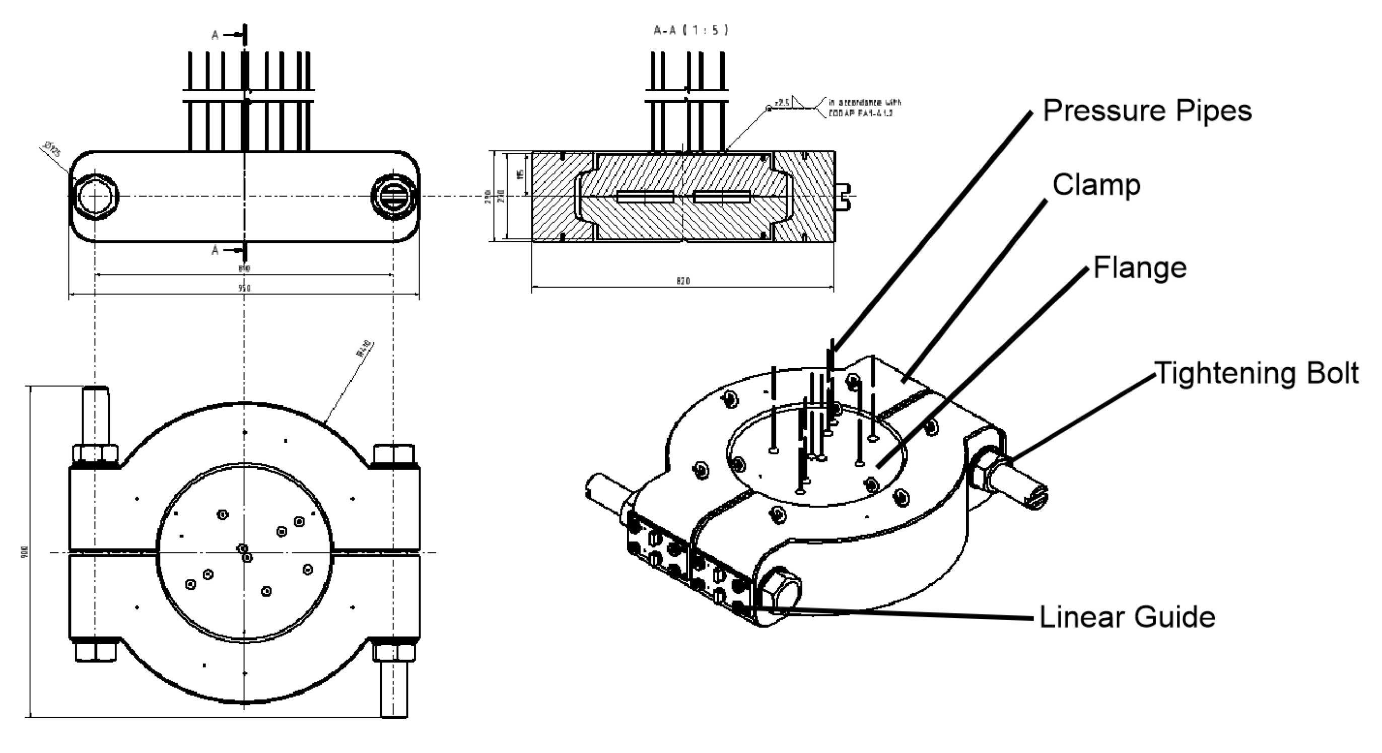
Figure 16.
Technical drawing of the MPC Test Bench.
Figure 16.
Technical drawing of the MPC Test Bench.
Table 1.
Comparison between multiple breeding blanket-cooling concepts [
2].
Table 1.
Comparison between multiple breeding blanket-cooling concepts [
2].
| Blanket Concept | DCLL | HCLL | WCLL | HCPB |
| Coolant Medium | He and PbLi | He | Water | He |
| Coolant Inlet Temperature | 300 °C | 300 °C | 295 °C | 300 °C |
| Coolant Outlet Temperature | 425 °C | 542 °C | 328 °C | 550 °C |
| Coolant Design Pressure | 9.6 MPa | 9.6 MPa | 18.6 MPa | 9.6 MPa |
| Tritium Removal Medium | PbLi | PbLi | PbLi | He |
| Tritium Removal Design Pressure | 9.6 MPa | 9.6 MPa | 18.6 MPa | 9.6 MPa |
Table 2.
Comparison between two concept designs.
Table 2.
Comparison between two concept designs.
| | Hub-and-Clamp | Compact-Flange Concept |
|---|
| Advantage | Better Overall Force distribution | Lower space footprint |
| Disadvantage | Tooling access | Inhomogeneous sealing force distribution |
| Footprint (W/L/H [mm]) | 866/145/925 | 1020/825/800 |
Table 3.
ASME VIII-Div 1 Appendix 24 calculation results.
Table 3.
ASME VIII-Div 1 Appendix 24 calculation results.
| Stress Category | MPC Stress Value, MPa
(Operational/Assembly) | Allowed Max Stress Value, MPa
(Operational/Assembly) | Ratio between Calculated and
Allowed Max Stress Value
(Operational/Assembly) |
|---|
| Hub Longitudinal Stress | 12.69/628.36 | 261/325.5 | 0.05/1.93 |
| Hub Loop Stress | 85.83/0 | 174/217 | 0.49/0 |
| Hub Axial Shear Stress | 39.22/79.50 | 139.2/173.6 | 0.28/0.46 |
| Hub Radial Shear Stress | 0.41/104.02 | 139.2/173.6 | 0/0.6 |
| Clamp Longitudinal Stress | 108.41/219.74 | 261/325.5 | 0.42/0.68 |
| Clamp Tangential Stress | −6.57/277.09 | 261/325.5 | −0.02/0.85 |
| Clamp Lip Shear Stress | 80.72/163.62 | 139.2/173.6 | 0.58/0.94 |
| Clamp Lug Bending Stress | −1.09/45.87 | 174/217 | 0/0.21 |
| Clamp to Hub Contact Stress | 67.27/136.35 | 278.4/278.4 | 0.24/0.49 |
| Disclaimer/Publisher’s Note: The statements, opinions and data contained in all publications are solely those of the individual author(s) and contributor(s) and not of MDPI and/or the editor(s). MDPI and/or the editor(s) disclaim responsibility for any injury to people or property resulting from any ideas, methods, instructions or products referred to in the content. |
© 2023 by the authors. Licensee MDPI, Basel, Switzerland. This article is an open access article distributed under the terms and conditions of the Creative Commons Attribution (CC BY) license (https://creativecommons.org/licenses/by/4.0/).


