

ITER Test Blanket Module—ALARA Investigations for Port Cell Pipe Forest Replacement
 , , , ,
Abstract
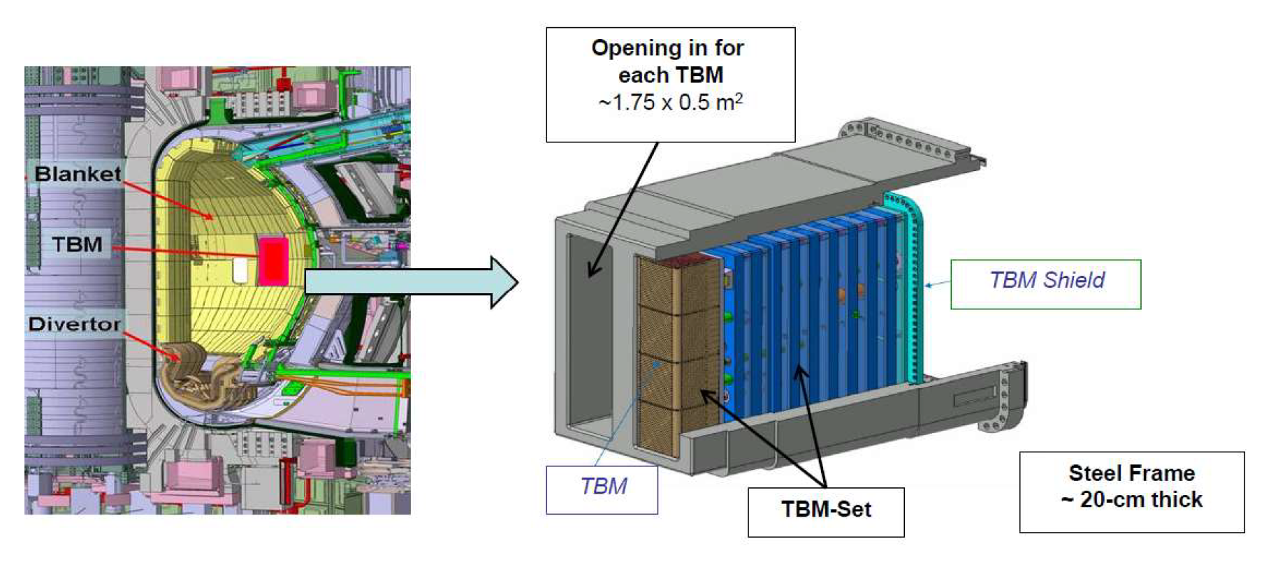
:1. Introduction: ITER Test Blanket Modules (TBMs)
2. ITER Test Blanket System (TBS) Testing Plan
3. Configuration for the Test Blanket Systems (TBS)
- Water-cooled lithium lead (WCLL) TBSs;
- Helium-cooled pebble bed (HCPB) or helium-cooled ceramic reflector (HCCR) TBSs.
- Water-cooled ceramic breeder (WCCB) TBS;
- Helium-cooled ceramic breeder (HCCB) TBS.
- Primary cooling system, either helium (HCS) or pressurized water (WCS);
- Coolant purification system (CPS);
- Tritium extraction system (TES);
- Pb16Li system as the tritium carrier;
- Tritium accountancy system (TAS);
- Instrumentation and control System (I&C);
- Neutron activation system (NAS), used to measure the neutron flux and fluency within the TBM.
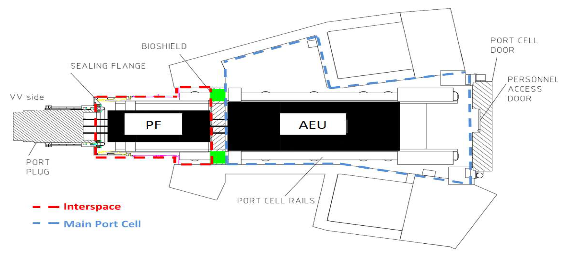
- To manage the TBS local processes in port cells, including, for example, two isolation valves per pipe in order to limit the effect of in-vessel and ex-vessel accidental cases and the local Pb16Li loop in the case of a liquid breeder.
- To provide the junction between the port plug mounted on the VV and the TBM feeding pipes transporting the cooling fluids, the tritium purge gas lines and also sample transfer lines for the neutron activation system (NAS) (measuring the local neutron flux and fluence within the TBM).
- To interface with the tokamak building and services through the common equipment, such as electrical power distribution, detritiation system for room ventilation, helium gas, cooling water, compressed air, instrumentation and control system (I&C) cabling, and vacuum detection services.
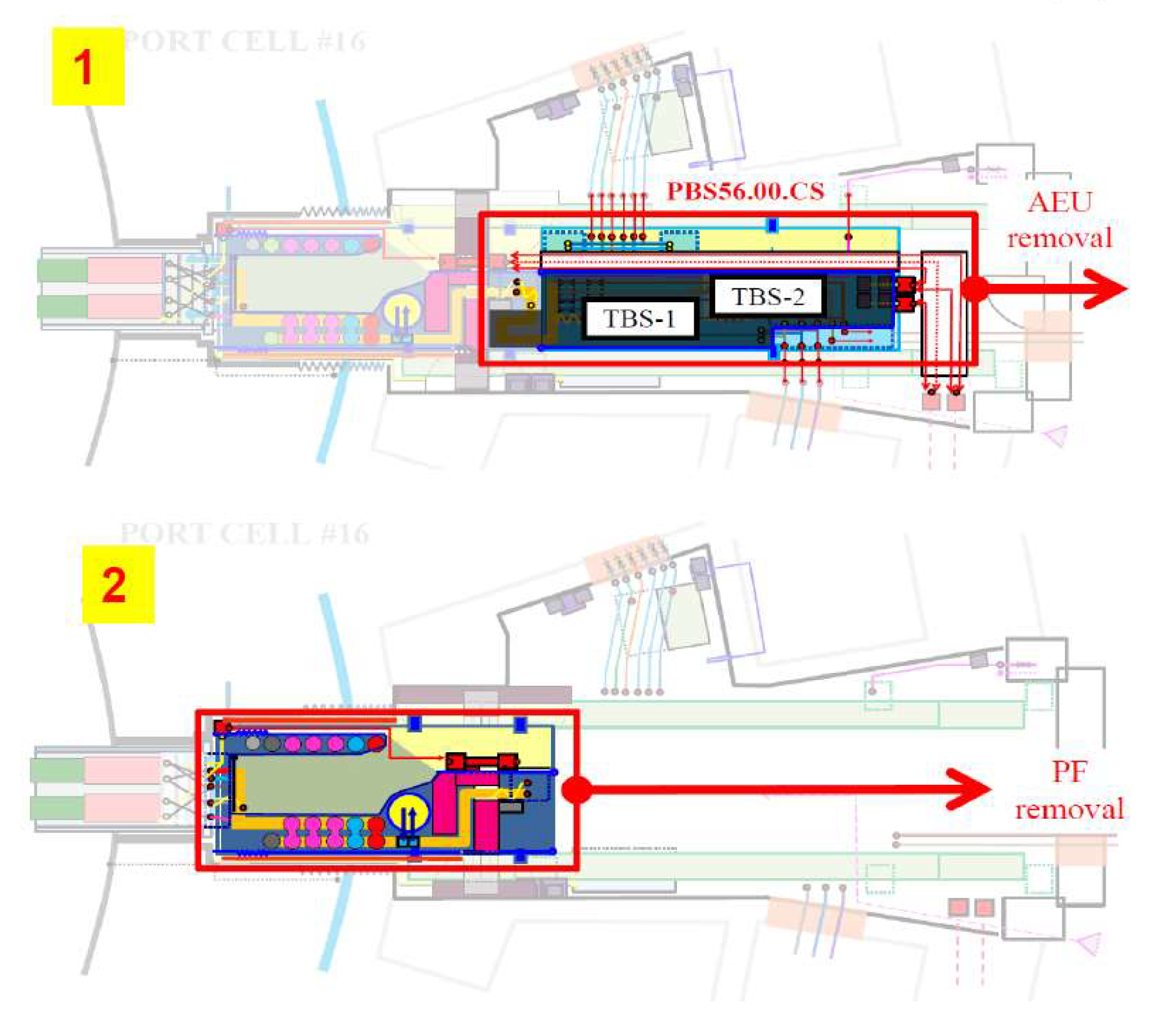
4. Replacement Sequence of the ITER Test Blanket Modules (TBMs)
5. ALARA for TBS Replacement Operations
- Source reduction;
- Improvement in shielding (e.g., local shielding);
- Increasing the distance between workers and sources;
- Ensuring good ventilation (e.g., flow rate, air renewal, etc.).
- Specifying high standards for equipment to ensure very low failure rates, (e.g., equipment quality class, etc.);
- Ensuring ease of maintenance or ease of removal of equipment;
- Simplifying operating procedures;
- Ensuring ease of access and good lighting (e.g., ergonomics, etc.).
- Human access equip. (scaffolding, stairs, etc.);
- Temporary lifting devices (floor-based);
- Visual equip. (cameras, lights, etc.);
- Detectors;
- Personal protection equipment;
- Temporary local shielding (lead bricks, etc.);
- Decontamination equipment;
- Radwaste handling/storage equipment.
- Provisions against external exposure:
- -
- Radiological zoning;
- -
- Radiation shields;
- -
- Choice of materials;
- -
- Dose optimization through design changes;
- -
- Remote handling and maintenance;
- -
- Access control systems;
- -
- Minimizing occupational exposure times;
- -
- Limiting surface and atmospheric contamination;
- -
- Monitoring systems.
- Provisions against internal exposure:
- -
- Collective protective means;
- -
- Static confinement;
- -
- Dynamic confinement;
- -
- Personal protective equipment (PPE).
- -
- Justification: The activity to replace the pipe forest is required to implement the ITER test blanket systems (TBS) as per the ITER research plan (see Section 1).
- -
- Optimization: “Protection is optimized” means that optimization of protection has been applied and the result of that process has been implemented:
- The collective dose will be used as an instrument for optimization;
- ORE initial assessment will identify the highest priority area of optimization;
- Iterative optimization steps will allow the reduction in dose personal exposure by means of available radiological technologies and protection procedures called dose reduction measures (DRM).
- -
- Dose limitation: This shall comply with any relevant dose limit from project guidelines on occupational exposure [10]:
- Individual worker dose rate of 0.1 mSv/h;
- Annual individual worker dose of 10 mSv/y;
- Annual individual average dose of 2.5 mSv/y (all workers);
- Collective annual worker dose of 500 mSv/y.
6. TBSs in PC Replacement Sequence: Initial ORE in FPO
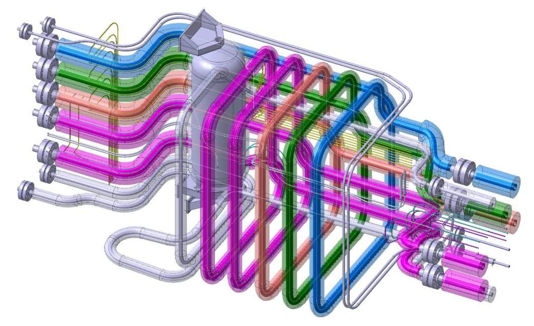
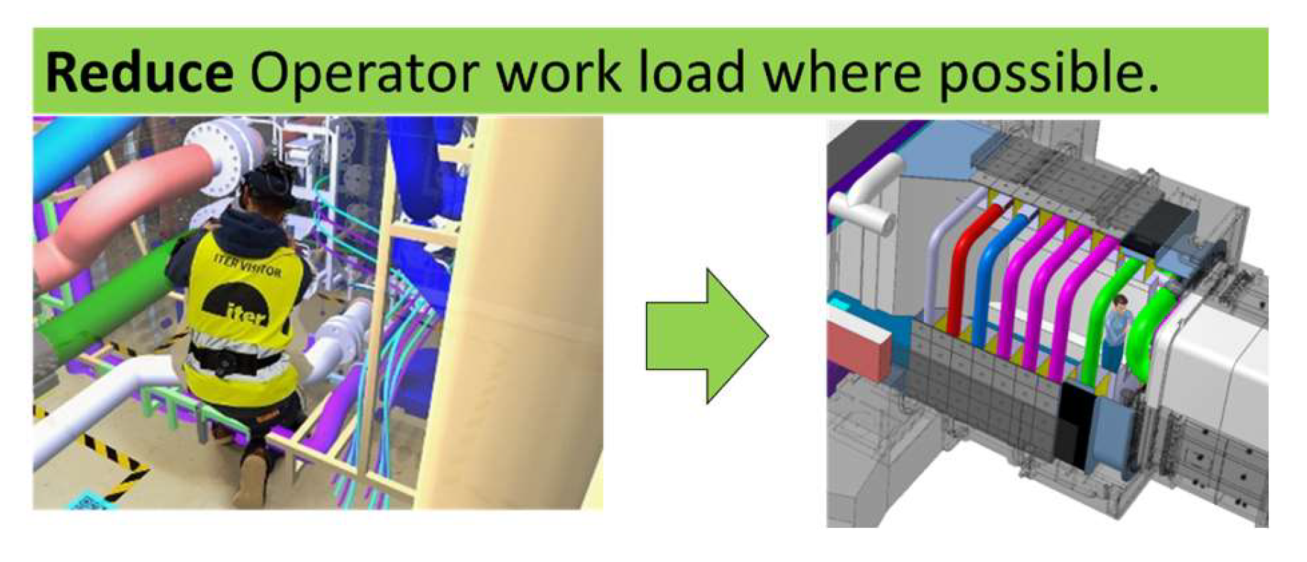
7. Reduction in Occupancy: PF Design Opportunity
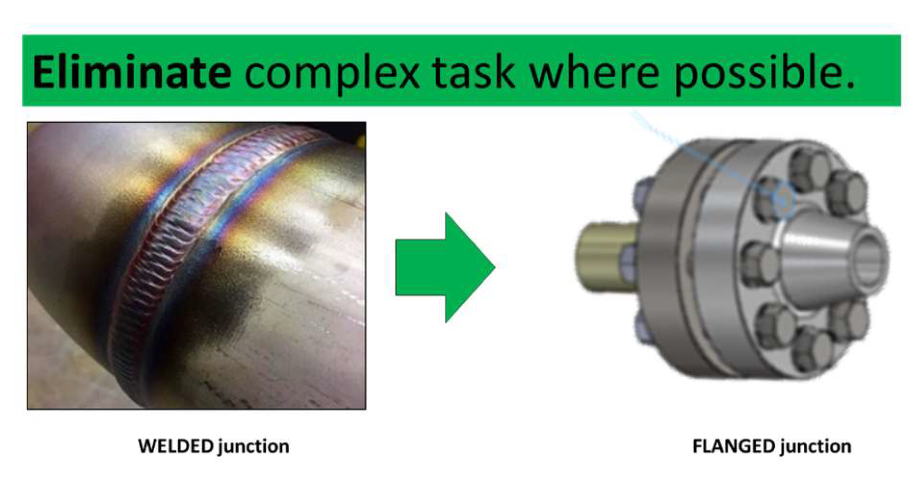
8. Reduction in Occupancy: PF Interface Opportunity
- Pipe end preparation;
- Pipe alignment;
- In-pipe inerting;
- Pipe pre-welding heat treatment;
- Pipe welding;
- Pipe visual inspection;
- Pipe penetrant test (PT);
- Pipe radiographic test (RT);
- Pipe post-welding heat treatment;
- Connect pipe heating wires;
- Install pipe thermal insulation.
9. ALARA and ORE Iterative Improvement Process
- Shielding:
- -
- Additional local shielding should be provided to reduce the radiation field as needed.
- Ventilation: In many facilities, the control of airborne contamination is achieved by
- -
- Maintaining adequate negative pressure with respect to atmospheric pressure;
- -
- Providing an adequate or prescribed number of air changes in the workplace;
- -
- Providing appropriate exhaust air, so that the discharges from the facility will be within authorized limits.
- Dust control (risk of dust release during the disassembly process and/or dry processing of radioactive material).
- -
- The generation of dust in operations should be reduced to the extent practicable by the use of appropriate techniques;
- -
- Where dust is generated, it should be suppressed at the source. Where necessary and practicable, the source should be enclosed under negative air pressure;
- -
- Dust that has not been suppressed at the source may be diluted to acceptable levels by means of frequent changes in air in the working area;
- -
- Care should be taken to avoid the resuspension of dust as a result of high air velocities;
- -
- Where methods of dust control do not achieve acceptable air quality in working areas, enclosed operating booths with filtered air supplies should be provided for the workers.
- Spillage of radioactive material operating procedures to be followed in the event of any significant radiation hazard or potential radiation hazard arising from the spillage of radioactive material.
- -
- Cleaning up spillages: The area should be decontaminated by the removal of all loose contamination and contaminated materials to the greatest extent practicable;
- -
- Restricting access to the area.
- Surface contamination work with unsealed radioactive substances creates the potential for contamination of surfaces. The physical design features used for contamination control may include the following:
- -
- Specific design features aimed at confining radioactive material to prevent it from causing surface contamination;
- -
- Ventilation systems aimed at preventing the build-up of surface contamination as a result of the settling of airborne particles;
- -
- Monitoring for surface contamination;
- -
- Housekeeping.
- Decontamination of equipment and decontamination of personnel
- -
- Decontamination of equipment and areas of floors and walls;
- -
- Decontamination of personnel.
10. Conclusions
- -
- AEU and PF systems’ design maturity is low;
- -
- Sequence definition maturity (steps and duration) is low;
- -
- There is high uncertainty regarding occupancy time (~1:8), highly reliant on working conditions (work in suits, workstation configuration, etc.).
11. Perspectives
12. Disclaimer
Author Contributions
Funding
Data Availability Statement
Conflicts of Interest
References
- Giancarli, L.; Abdou, M.; Campbell, D.; Chuyanov, V.; Ahn, M.; Enoeda, M.; Pan, C.; Poitevin, Y.; Kumar, E.R.; Ricapito, I.; et al. Overview of the ITER TBM Program. Fusion Eng. Des. 2012, 87, 395–402. [Google Scholar] [CrossRef]
- Giancarli, L.M.; Bravo, X.; Cho, S.; Ferrari, M.; Hayashi, T.; Kim, B.-Y.; Leal-Pereira, A.; Martins, J.-P.; Merola, M.; Pascal, R.; et al. Overview of recent ITER TBM Program activities. Fusion Eng. Des. 2020, 158, 111674. [Google Scholar] [CrossRef]
- Campbell, D.J.; Akiyama, T.; Barnsley, R.; Bassan, M.; Baylor, L.R.; Bertalot, L.; Escourbiac, F.; Giancarli, L.M.; Gitton, P.; Guirao, J.; et al. Innovations in Technology and Science R&D for ITER. J. Fusion Energy 2019, 38, 11–71. [Google Scholar] [CrossRef]
- Giancarli, L.; Barabash, V.; Campbell, D.; Chiocchio, S.; Cordier, J.-J.; Dammann, A.; Dell’Orco, G.; Elbez-Uzan, J.; Fourneron, J.; Friconneau, J.; et al. Progress and challenges of the ITER TBM Program from the IO perspective. Fusion Eng. Des. 2016, 109–111, 1491–1497. [Google Scholar] [CrossRef]
- Giancarli, L.M.; Ahn, M.-Y.; Bonnett, I.; Boyer, C.; Chaudhuri, P.; Davis, W.; Dell’Orco, G.; Iseli, M.; Michling, R.; Neviere, J.-C.; et al. ITER TBM Program and associated system engineering. Fusion Eng. Des. 2018, 136, 815–821. [Google Scholar] [CrossRef]
- Harb, M.; Park, J.H.; Leichtle, D.; Martins, J.P.; Kim, B.Y.; van der Laan, J.G.; Bergman, J. Neutronics analysis and assessment of shielding options of pipe forest and Bioshield-Plug design for ITER TBSs. Fusion Eng. Des. 2021, 168, 112402. [Google Scholar] [CrossRef]
- Martins, J.-P.; Friconneau, J.-P.; Gabellini, E.; Keller, D.; Levesy, B.; Selvi, A.; Tesini, A.; Utin, Y.; Wagrez, J. Cask and plug handling system design in port cell. Fusion Eng. Des. 2011, 86, 1886–1889. [Google Scholar] [CrossRef]
- International Atomic Energy Agency. Occupational Radiation Protection: IAEA Safety Standards Series No. GSG-7; IAEA: Vienna, Austria, 2018. [Google Scholar]
- International Atomic Energy Agency. Optimization of Radiation Protection in the Control of Occupational Exposure, Safety Reports Series No. 21; IAEA: Vienna, Austria, 2002. [Google Scholar]
- Maubert, H.; Pinna, T.; Porfiri, M.-T.; Ciattaglia, S. Radiological protection in ITER. Radioprotection 2007, 42, 519–534. [Google Scholar] [CrossRef] [Green Version]
- Burgess, T.W.; Evans, J.H.; Peishel, F.L.; Schrock, S.L.; Smith, G.E.; Macdonald, D. Design Guidelines for Remotely Maintained Equipment; ONRL: Oak Ridge, TN, USA, 1988. [Google Scholar]
- RCC-MRx Code. Available online: https://www.afcen.com/fr/106-rcc-mrx (accessed on 1 June 2022).
- Gazzotti, S.; Ferlay, F.; Meunier, L.; Viudes, P.; Huc, K.; Derkazarian, A.; Friconneau, J.-P.; Peluso, B.; Martins, J.-P. Virtual and Augmented Reality Use Cases for Fusion Design Engineering. Fusion Eng. Des. 2021, 172, 112780. [Google Scholar] [CrossRef]
- Zaouter, T.; Vulliez, K.; Michel, B.; Gazzotti, S.; Friconneau, J.-P.; Martins, J.-P. Assessment of a bolted-flange connection for ITER Test Blanket Module. Fusion Eng. Des. 2021, 165, 112247. [Google Scholar] [CrossRef]
- David, O.; Andre, S.; Kfoury, F.; Garrec, P. Cobomanip: A new generation of Intelligent Assist Device. In Proceedings of the ISR/Robotik 2014, 41st International Symposium on Robotics, Munich, Germany, 2–3 June 2014; pp. 1–8. [Google Scholar]
- Restrepo, S.S.; Raiola, G.; Chevalier, P.; Lamy, X.; Sidobre, D. Iterative virtual guides programming for human-robot comanipulation. In Proceedings of the 2017 IEEE International Conference on Advanced Intelligent Mechatronics (AIM), Munich, Germany, 3–7 July 2017; pp. 219–226. [Google Scholar]


| Workstations | Occupancy Time% | Occupancy Dose% |
|---|---|---|
| # 1 (in Gallery) | 37 | 2 |
| # 2 (in PC area) | 6 | 2 |
| # 3 (in PC area) | 8 | 3 |
| # 4 (in PC area) | 23 | 20 |
| # 5 (in PI area) | 2 | 3 |
| # 6 (in PI area) | 24 | 70 |
Disclaimer/Publisher’s Note: The statements, opinions and data contained in all publications are solely those of the individual author(s) and contributor(s) and not of MDPI and/or the editor(s). MDPI and/or the editor(s) disclaim responsibility for any injury to people or property resulting from any ideas, methods, instructions or products referred to in the content. |
© 2023 by the authors. Licensee MDPI, Basel, Switzerland. This article is an open access article distributed under the terms and conditions of the Creative Commons Attribution (CC BY) license (https://creativecommons.org/licenses/by/4.0/).
Share and Cite
Friconneau, J.-P.; Batal, T.; David, O.; Di Paolo, C.; Ferlay, F.; Gazzotti, S.; Giancarli, L.; Lacroix, C.; Martins, J.-P.; Michel, B.; et al. ITER Test Blanket Module—ALARA Investigations for Port Cell Pipe Forest Replacement. J. Nucl. Eng. 2023, 4, 297-308. https://doi.org/10.3390/jne4010022
Friconneau J-P, Batal T, David O, Di Paolo C, Ferlay F, Gazzotti S, Giancarli L, Lacroix C, Martins J-P, Michel B, et al. ITER Test Blanket Module—ALARA Investigations for Port Cell Pipe Forest Replacement. Journal of Nuclear Engineering. 2023; 4(1):297-308. https://doi.org/10.3390/jne4010022
Chicago/Turabian StyleFriconneau, Jean-Pierre, Tristan Batal, Olivier David, Chiara Di Paolo, Fabien Ferlay, Stéphane Gazzotti, Luciano Giancarli, Christophe Lacroix, Jean-Pierre Martins, Benjamin Michel, and et al. 2023. "ITER Test Blanket Module—ALARA Investigations for Port Cell Pipe Forest Replacement" Journal of Nuclear Engineering 4, no. 1: 297-308. https://doi.org/10.3390/jne4010022